WO2016121855A1 - 投射型表示装置用カラーホイール及びその製造方法、並びにこれを含む投射型表示装置 - Google Patents
投射型表示装置用カラーホイール及びその製造方法、並びにこれを含む投射型表示装置 Download PDFInfo
- Publication number
- WO2016121855A1 WO2016121855A1 PCT/JP2016/052454 JP2016052454W WO2016121855A1 WO 2016121855 A1 WO2016121855 A1 WO 2016121855A1 JP 2016052454 W JP2016052454 W JP 2016052454W WO 2016121855 A1 WO2016121855 A1 WO 2016121855A1
- Authority
- WO
- WIPO (PCT)
- Prior art keywords
- light
- display device
- adjustment layer
- color wheel
- light adjustment
- Prior art date
- Legal status (The legal status is an assumption and is not a legal conclusion. Google has not performed a legal analysis and makes no representation as to the accuracy of the status listed.)
- Ceased
Links
Images


Classifications
-
- F—MECHANICAL ENGINEERING; LIGHTING; HEATING; WEAPONS; BLASTING
- F21—LIGHTING
- F21V—FUNCTIONAL FEATURES OR DETAILS OF LIGHTING DEVICES OR SYSTEMS THEREOF; STRUCTURAL COMBINATIONS OF LIGHTING DEVICES WITH OTHER ARTICLES, NOT OTHERWISE PROVIDED FOR
- F21V9/00—Elements for modifying spectral properties, polarisation or intensity of the light emitted, e.g. filters
- F21V9/30—Elements containing photoluminescent material distinct from or spaced from the light source
-
- F—MECHANICAL ENGINEERING; LIGHTING; HEATING; WEAPONS; BLASTING
- F21—LIGHTING
- F21V—FUNCTIONAL FEATURES OR DETAILS OF LIGHTING DEVICES OR SYSTEMS THEREOF; STRUCTURAL COMBINATIONS OF LIGHTING DEVICES WITH OTHER ARTICLES, NOT OTHERWISE PROVIDED FOR
- F21V13/00—Producing particular characteristics or distribution of the light emitted by means of a combination of elements specified in two or more of main groups F21V1/00 - F21V11/00
- F21V13/12—Combinations of only three kinds of elements
- F21V13/14—Combinations of only three kinds of elements the elements being filters or photoluminescent elements, reflectors and refractors
-
- F—MECHANICAL ENGINEERING; LIGHTING; HEATING; WEAPONS; BLASTING
- F21—LIGHTING
- F21V—FUNCTIONAL FEATURES OR DETAILS OF LIGHTING DEVICES OR SYSTEMS THEREOF; STRUCTURAL COMBINATIONS OF LIGHTING DEVICES WITH OTHER ARTICLES, NOT OTHERWISE PROVIDED FOR
- F21V9/00—Elements for modifying spectral properties, polarisation or intensity of the light emitted, e.g. filters
- F21V9/08—Elements for modifying spectral properties, polarisation or intensity of the light emitted, e.g. filters for producing coloured light, e.g. monochromatic; for reducing intensity of light
-
- F—MECHANICAL ENGINEERING; LIGHTING; HEATING; WEAPONS; BLASTING
- F21—LIGHTING
- F21V—FUNCTIONAL FEATURES OR DETAILS OF LIGHTING DEVICES OR SYSTEMS THEREOF; STRUCTURAL COMBINATIONS OF LIGHTING DEVICES WITH OTHER ARTICLES, NOT OTHERWISE PROVIDED FOR
- F21V9/00—Elements for modifying spectral properties, polarisation or intensity of the light emitted, e.g. filters
- F21V9/40—Elements for modifying spectral properties, polarisation or intensity of the light emitted, e.g. filters with provision for controlling spectral properties, e.g. colour, or intensity
- F21V9/45—Elements for modifying spectral properties, polarisation or intensity of the light emitted, e.g. filters with provision for controlling spectral properties, e.g. colour, or intensity by adjustment of photoluminescent elements
-
- G—PHYSICS
- G02—OPTICS
- G02B—OPTICAL ELEMENTS, SYSTEMS OR APPARATUS
- G02B5/00—Optical elements other than lenses
- G02B5/02—Diffusing elements; Afocal elements
-
- G—PHYSICS
- G03—PHOTOGRAPHY; CINEMATOGRAPHY; ANALOGOUS TECHNIQUES USING WAVES OTHER THAN OPTICAL WAVES; ELECTROGRAPHY; HOLOGRAPHY
- G03B—APPARATUS OR ARRANGEMENTS FOR TAKING PHOTOGRAPHS OR FOR PROJECTING OR VIEWING THEM; APPARATUS OR ARRANGEMENTS EMPLOYING ANALOGOUS TECHNIQUES USING WAVES OTHER THAN OPTICAL WAVES; ACCESSORIES THEREFOR
- G03B21/00—Projectors or projection-type viewers; Accessories therefor
- G03B21/14—Details
Definitions
- the present invention relates to a color wheel for a projection display device, a manufacturing method thereof, and a projection display device including the same.
- a projection display device (projector) has been developed for enlarging and projecting a screen of a personal computer, a playback moving image from various image playback devices, or the like onto a screen or the like.
- a projector using a high-intensity discharge lamp as a light source has been mainly used.
- Patent Document 1 a projection type display device using a light emitting diode or a laser.
- Patent Document 1 a projection display device that arranges three types of light sources of red, green, and blue and performs color display by combining these light sources.
- a projection display device having a light source that emits ultraviolet light and a color wheel that includes three kinds of phosphor-containing layers that emit red, green, and blue excitation light when irradiated with ultraviolet light has also been proposed.
- color display is performed by combining light of each color emitted from the color wheel.
- the color wheel is usually composed of a disk-shaped substrate and a phosphor layer formed on the substrate, and the phosphor layer contains a phosphor and a binder resin.
- a projection display device having a color wheel can perform color display even with a single light source. Therefore, there is an advantage that the apparatus can be downsized.
- the resin binder in the phosphor layer of the color wheel deteriorates due to light and heat from the light source, and there is a problem that the phosphor is peeled off or the resin itself is colored and the phosphor layer is discolored. It was.
- the substrate is made of an inorganic material, there is a problem that peeling between the substrate and the phosphor layer is likely to occur due to thermal shock.
- the present invention has been made in view of the above problems, and the phosphor and the diffusing material do not peel off over a long period of time, and further, there is little discoloration of emitted light, etc.
- a manufacturing method and a projection display device including the same are provided.
- the first of the present invention relates to a color wheel for a projection display device shown below.
- a color wheel for a projection display device shown below.
- a projection display device having a substrate, a ceramic binder formed on the substrate and made of a reaction product of a ceramic precursor, and a light adjustment layer containing at least one of a phosphor and a diffusion material Color wheel.
- the ceramic precursor is one or more polysiloxane precursors selected from the group consisting of polysilazane, an alkoxysilane monomer, and an alkoxysilane oligomer.
- the diffusion material is made of one or more inorganic compounds selected from the group consisting of titanium oxide, silicon oxide, barium sulfate, barium titanate, boron nitride, zinc oxide, and aluminum oxide, and has an average primary particle size.
- the color wheel for a projection display device according to any one of [1] to [3], wherein the color wheel is a particle of 100 nm to 10 ⁇ m.
- the light adjustment layer includes the diffusion material and the phosphor, and includes the diffusion material in a range of 34% by mass to less than 70% by mass with respect to the total amount of the phosphor and the diffusion material.
- the substrate has at least a reflective surface made of metal on a surface adjacent to the light adjustment layer, and the light adjustment layer includes a structure derived from a mercapto group-containing coupling agent.
- the light adjusting layer has any one of [1] to [6], wherein the thickness of the end portion is smaller than the thickness of the center portion, and the thickness of the end portion is 50 to 70% with respect to the thickness of the center portion.
- 2nd of this invention is related with the manufacturing method of the color wheel for projection type display apparatuses shown below.
- a method for producing a color wheel for a projection display device comprising: applying a composition for forming a light adjustment layer comprising: to the substrate and curing by heating to form the light adjustment layer.
- a method for producing a color wheel for a projection display device comprising: applying a composition for forming a light adjustment layer comprising: to the substrate and curing by heating to form the light adjustment layer.
- the method for producing a color wheel for a projection display device comprising: applying a composition for forming a light adjustment layer comprising: to the substrate and curing by heating to form the light adjustment layer.
- the method for producing a color wheel for a projection display device according to [8] or [9], wherein the ceramic precursor-containing composition or the light adjusting layer forming composition is applied by a spray or a dispenser.
- the color wheel for a projection display device according to [8] or [9], wherein the ceramic precursor-containing composition or the light adjustment layer forming composition is applied by spraying while rotating the substrate. Manufacturing method.
- a third aspect of the present invention relates to a projection display device described below. [12] A projection display device including the color wheel for the projection display device according to any one of [1] to [7].
- a projection type display device can be obtained in which phosphors and diffusing materials do not peel over a long period of time, and further, there is little discoloration of light emitted from the color wheel. .
- FIG. 2 is a cross-sectional view taken along the line A-A ′ of the color wheel for the projection display device of FIG. 1. It is a figure for demonstrating the spray apparatus for apply
- Color wheel for projection display device The color wheel for projection display device of the present invention (hereinafter also referred to as “color wheel”) has a structure in which a substrate and a light adjustment layer containing a diffusing material or a phosphor are laminated. .
- the color wheel is installed between the light source and the projection optical system in the projection display device, and functions to diffuse light from the light source or convert light from the light source into light of another specific wavelength.
- the color wheel of the present invention only one type of light adjustment layer 2 may be formed on one substrate 1.
- different types of light adjustment layers 2a to 2c may be formed in different regions of one substrate 1.
- the light adjustment layer 2a including a phosphor that receives blue light and emits green, and the fluorescence that emits red by receiving blue light It can be set as the color wheel 100 containing the light adjustment layer 2b containing a body, and the light adjustment layer 2c containing the diffusion material for diffusing blue light.
- the light adjustment layer 2a including a phosphor that emits green light by receiving ultraviolet light, and the fluorescence that emits red light by receiving ultraviolet light.
- the color wheel 100 can include the light adjustment layer 2b including a body and the light adjustment layer 2c including a phosphor that emits blue light when receiving ultraviolet light. In this way, by combining a plurality of light adjustment layers 2, the three primary colors of light can be reproduced even if only one type of light source is used.
- the type of light adjustment layer included in the color wheel 100, the region where the light adjustment layer is formed, and the like are appropriately selected according to the type of the projection display device, the wavelength of light from the light source, the structure of the optical system, and the like. Selected.
- the color wheel of the present invention is a transmissive color wheel that transmits light incident from one surface of the color wheel 100 to the other surface side (hereinafter referred to as “transmissive color wheel”). May also be referred to). Further, it may be a reflective color wheel that reflects light incident on the color wheel 100 in a predetermined direction (hereinafter also referred to as “reflective color wheel”). In any color wheel, light incident on the light adjustment layer is diffused and / or wavelength-converted by a diffusing material or a phosphor.
- the color wheel for a projection display device not only receives strong light from the light source but also receives heat from the light source.
- the conventional color wheel including the binder resin has problems such as the phosphor and diffusing particles falling off due to the deterioration of the binder resin, and the light emitted from the light adjusting layer being discolored due to the coloring of the binder resin.
- the substrate is an inorganic material such as a metal material or a glass substrate, the linear expansion coefficients of the substrate and the light adjustment layer are greatly different, and the light adjustment layer is easily peeled off due to thermal shock.
- the binder is made of a reaction product of a ceramic precursor. For this reason, even when heat or light is received from the light source, the phosphor and the diffusing particles are not easily dropped off, and further, there is little discoloration. As a result, the light adjustment layer can stably perform light diffusion and wavelength conversion over a long period of time. Further, even when subjected to a thermal shock, peeling at the interface between the light adjustment layer and the substrate hardly occurs.
- the substrate of the color wheel for a projection display device of the present invention is a member for holding the light adjustment layer.
- the shape of the substrate is not particularly limited and is appropriately selected according to the use of the color wheel and the like, and can be the same as a substrate for a general projection display device.
- the color wheel is a transmissive color wheel
- the light from the light source enters the light adjustment layer of the color wheel, and the light is diffused and / or wavelength-converted. Thereafter, the light passes through the substrate and is guided to the projection optical system through a predetermined path.
- the substrate is required to have optical transparency.
- a light-transmitting substrate include a substrate made of a heat-resistant transparent resin and a substrate made of a light-transmitting ceramic. From the viewpoint of the heat resistance and discoloration resistance of the substrate, the light-transmitting property is used. It is preferable that the substrate is made of ceramic. Particularly preferred is a glass substrate.
- the color wheel is a reflective color wheel
- the light from the light source enters the light adjustment layer, and the light is diffused and / or wavelength-converted. Thereafter, the light is reflected at the interface between the substrate and the light adjustment layer or the like and guided to the projection optical system through a predetermined path. That is, the substrate is required to have light reflectivity.
- a light-reflective substrate is a substrate having a reflective surface made of metal. Specifically, it can be a substrate made of metal, or a substrate in which a layer made of a metal having high reflectivity such as silver is laminated on the surface of a base member made of resin, ceramic, metal or the like.
- a metal reflective surface is normally arrange
- the light adjustment layer has a function of diffusing and / or wavelength-converting light in the color wheel.
- the light adjustment layer includes at least one of a diffusing material and a phosphor and a ceramic binder, and the diffusing material and the phosphor are bound by the ceramic binder.
- the thickness of the light adjusting layer is preferably 1 to 1000 ⁇ m, more preferably 30 to 500 ⁇ m.
- the thickness of the light adjustment layer is 1 ⁇ m or more, the light diffusibility and the wavelength conversion property by the light adjustment layer are likely to increase.
- the thickness of the light adjustment layer is 1000 ⁇ m or less, the projection display device can be miniaturized.
- the thickness of the light adjustment layer is a region of 10% with respect to the width (W) including the center in the width direction when the width of the light adjustment layer is W. It is set as the average value of the thickness of the light adjustment layer of W1). The thickness is measured with a stylus type surface shape measuring instrument or the like.
- the thickness of the light adjustment layer may be uniform in the entire region, but as shown in the schematic cross-sectional view of FIG. 3 (AA ′ cross-sectional view of FIG. 1),
- the end portion is preferably thinner than the portion. If the thickness of the end portion of the light adjustment layer 2 is thin to some extent, cracks are unlikely to occur during the formation of the light adjustment layer, and the thermal shock resistance of the light adjustment layer is likely to increase.
- the thickness of the end is the thickness of the region (W2 and W2 ′) from the end of the light adjustment layer 2 to 10% of the width (W) of the light adjustment layer 2. Average value.
- the thickness of the end portion of the light adjusting layer 2 is preferably 50 to 70%, more preferably 50 to 65%, still more preferably 50 to 60% with respect to the thickness of the central portion of the light adjusting layer. %.
- the thickness of the end portion of the light adjustment layer is within the above range, the strength of the light adjustment layer is likely to increase.
- the shape of the end portion of the light adjustment layer can be adjusted by a method of applying a composition for forming the light adjustment layer, as will be described later.
- the light adjustment layer when only the light diffusibility is required for the light adjustment layer, the light adjustment layer includes a ceramic binder and a diffusion material.
- the light adjusting layer preferably contains a ceramic binder in an amount of 5 to 50% by weight, more preferably 5 to 40% by weight, and further preferably 5 to 30% by weight based on the weight of the light adjusting layer. % By mass.
- the amount of the ceramic binder is 5% by mass or more, the diffusion material is sufficiently bound, and the diffusion material does not easily fall off.
- the amount of the binder is 50% by mass or less, the amount of the diffusion material is relatively sufficient.
- the diffusing material is preferably contained in an amount of 50 to 95% by mass, more preferably 60 to 95% by mass, and still more preferably 70% by mass with respect to the mass of the light adjustment layer. ⁇ 95% by mass.
- the amount of the diffusing material is 50% by mass or more, the light that has passed through the light adjustment layer is easily diffused.
- the amount of the diffusing material is excessive, light cannot sufficiently enter the light adjusting layer, and it is difficult to obtain sufficient light diffusibility.
- the amount of the diffusing material is 95% by mass or less, the light from the light source is sufficiently diffused by the light adjustment layer.
- the light adjustment layer includes at least a ceramic binder and a phosphor, and further includes a diffusion material.
- the diffusing material is included together with the phosphor, the light wavelength-converted by the phosphor is more easily diffused. Furthermore, the light from the light source incident on the light adjustment layer is diffused, so that the light is easily absorbed by the phosphor. That is, the wavelength conversion property of light by the light adjustment layer is likely to increase. Furthermore, if the diffusion is insufficient, the incident light is extracted as it is from the light adjustment layer, and from the viewpoint that it is difficult to extract only light of a desired wavelength, the diffusion particles are formed in the light adjustment layer. It is preferably included.
- the amount of the ceramic binder contained in the light adjustment layer is preferably 5 to 50% by mass, more preferably 5 to 5% by mass with respect to the mass of the light adjustment layer. It is 40% by mass, and more preferably 5-30% by mass.
- the amount of the ceramic binder is 5% by mass or more, the diffusing material and the phosphor are sufficiently bound, and the diffusing material and the like are not easily dropped.
- the amount of the binder is 50% by mass or less, the amount of the diffusing material or the phosphor is relatively sufficient, and the light diffusibility and the wavelength conversion property of the light adjustment layer are easily increased.
- the amount of the phosphor contained in such a light adjustment layer is preferably 50 to 95% by mass, more preferably 60 to 95% by mass, and still more preferably relative to the mass of the light adjustment layer. 70 to 95% by mass.
- the amount of the phosphor is in the above range, the wavelength conversion property of the light adjustment layer is likely to be improved.
- the amount of the diffusing particles contained in the light adjusting layer is preferably 34% by mass or more and less than 70% by mass, more preferably 34 to 60% by mass with respect to the total amount of the phosphor and the diffusing particles. More preferably, it is 34 to 50% by mass.
- the amount of the diffusing particles contained in the light adjustment layer is within the above range, the wavelength conversion property of the light adjustment layer is likely to be improved.
- the light diffusibility by the diffusing particles is insufficient, that is, if the amount of diffusing particles is too small, as described above, light having a wavelength incident on the light adjustment layer is emitted from the light adjustment layer as it is, It becomes difficult to extract light having a desired wavelength.
- the amount of diffusing particles contained in the light adjustment layer is excessive, the required light extraction efficiency may be reduced.
- the amount of the light diffusing particles is within the above range, the balance between the light diffusibility and the light extraction property becomes good.
- the diffusion particles contained in the light adjustment layer are not particularly limited as long as they have high light diffusibility, and may be inorganic particles having an average primary particle size of 100 nm to 10 ⁇ m.
- the average primary particle size of the diffusing particles is more preferably from 100 nm to 5 ⁇ m, still more preferably from 200 nm to 2.5 ⁇ m.
- the average primary particle size in the present invention refers to the value of D50 measured with a laser diffraction particle size distribution meter. Examples of the laser diffraction particle size distribution measuring device include a laser diffraction particle size distribution measuring device manufactured by Shimadzu Corporation.
- the total reflectance of the diffusing particles is preferably 80% or more, and more preferably 90% or more.
- the total reflectance of the diffusing particles can be measured with a Hitachi spectrophotometer U4100 manufactured by Hitachi High-Tech.
- the diffusion particles include zinc oxide (ZnO), silicon oxide (SiO 2 ), barium titanate (BaTiO 3 ), barium sulfate (BaSO 4 ), titanium oxide (TiO 2 ), and boron nitride (BrN). , Magnesium oxide (MgO), calcium carbonate (CaCO 3 ), aluminum oxide (Al 2 O 3 ), barium sulfate (BaO), zirconium oxide (ZrO 2 ), and the like. From the viewpoints of light diffusibility and handleability, the diffusing particles are more preferably titanium oxide, silicon oxide, barium sulfate, barium titanate, boron nitride, zinc oxide, and aluminum oxide.
- the light adjusting layer may contain only one kind of diffusing particles or two or more kinds.
- the phosphor included in the light adjustment layer preferably has an average primary particle size of 1 to 30 ⁇ m, more preferably 5 to 30 ⁇ m, and even more preferably 10 to 30 ⁇ m.
- the particle size of the phosphor is too large, a gap generated between the phosphors becomes large, and light from the light source easily passes through the light adjustment layer as it is, and a desired wavelength conversion property may not be obtained. is there.
- the average primary particle diameter of the phosphor is measured by the same method as that for the aforementioned diffusion material.
- the phosphor is not particularly limited as long as it is excited by a specific wavelength (excitation wavelength) and emits fluorescence having a wavelength different from the wavelength of the excitation light.
- excitation wavelength a specific wavelength
- fluorescence having a wavelength different from the wavelength of the excitation light.
- a phosphor that converts excitation light of ultraviolet to near ultraviolet light or blue wavelength into green, red, or the like can be used.
- Examples of phosphors for green light emission include sulfide-based ZnS: Cu, Al, oxynitride-based (Si, Al) 6 (O, N) 8 : Eu, silicate-based Zn 2 SiO 4 : Mn, Zn 2 SiO 4 : Mn, (Ba, Sr) 2 SiO 4 : Eu, aluminate-based BaAl 12 O 19 : Mn, BaMgAl 14 O 23 : Mn, SrAl 12 O 19 : Mn, ZnAl 12 O 19 : Mn, CaAl 12 O 19 : Mn and the like are included.
- red phosphors examples include sulfite (Ca, Sr) S: Eu, nitride (Ca, Sr) 2 Si 5 N 8 : Eu, (Ca, Sr) AlSiN 3 : Eu, Ca, SiN 2 : Eu, silicate system Y 2 SiO 5 : Eu, aluminate system, Y 3 Al 5 O 12 : Eu, apatite system Zn 3 (P 0 4 ) 2 : Mn, other Y 2 O 3 : Eu, YBO 3 : Eu, (Y, Gd) BO 3 : Eu, GdBO 3 : Eu, ScBO 3 : Eu, LuBO 3 : Eu, and the like.
- a ceramic binder is obtained by reacting a ceramic precursor, and may be a polymer obtained by chemically reacting a ceramic precursor.
- the ceramic precursor is not particularly limited as long as the ceramic can be obtained by reaction, and examples thereof include alkoxides of various metals from which the ceramic can be obtained by hydrolysis and polycondensation, and polysilazane from which the ceramic can be obtained by deammonia method. Etc. are included.
- the ceramic precursor is preferably a polysiloxane precursor from the viewpoint of ease of preparation of the ceramic binder, and is one or more compounds selected from the group consisting of polysilazane, alkoxysilane monomer, and alkoxysilane oligomer. Is more preferable.
- the ceramic precursor is particularly preferably an alkoxysilane oligomer.
- the ceramic precursor is a polysiloxane precursor
- the hydroxyl group present on the substrate surface and the silicon in the polysiloxane are likely to form a siloxane bond, and the adhesion between the substrate and the light adjustment layer is likely to increase.
- polysilazane is a compound represented by the general formula (I): (R 1 R 2 SiNR 3 ) n .
- R 1 , R 2 and R 3 each independently represent a hydrogen atom or an alkyl group, an aryl group, a vinyl group or a cycloalkyl group, but R 1 , R 2 and R 3 At least one of them is a hydrogen atom, preferably all are hydrogen atoms.
- n represents an integer of 1 to 60.
- the molecular shape of polysilazane may be any shape, for example, linear or cyclic.
- Polysilazane becomes polysiloxane by hydrolysis and deammonification. Specifically, polysiloxane is obtained by subjecting the polysilazane represented by the above formula (I) to heating, excimer light treatment, UV light treatment, etc. in the presence of a reaction accelerator and a solvent as necessary.
- the monomer or oligomer of alkoxysilane may be a monomer or oligomer of a bifunctional alkoxysilane compound, a trifunctional alkoxysilane compound, or a tetrafunctional alkoxysilane compound.
- the binder contains polysiloxane
- the polysiloxane preferably contains a structure derived from bifunctional alkoxysilane. If the polysiloxane contains a structure derived from a bifunctional alkoxysilane, the resulting polysiloxane has increased flexibility, and the thermal resistance to cold shock of the polysiloxane is likely to increase. In addition, cracks and the like hardly occur during the formation of the light adjustment layer.
- the amount of the structure derived from the bifunctional alkoxysilane contained in the polysiloxane is preferably 5 to 50 mol%, more preferably 10 to 30 mol%, based on all the structural units of the polysiloxane.
- the amount of the structural unit derived from the bifunctional alkoxysilane compound and the amount of the structural unit derived from other alkoxysilane (trifunctional or tetrafunctional alkoxysilane compound) contained in the polysiloxane is 29 Si-NMR (for example, JEOL Ltd.) It is possible to measure by company LA400).
- examples of the tetrafunctional alkoxysilane compound include a compound represented by the following general formula (II).
- Si (OR 4 ) 4 (II) In the general formula (II), each R 4 independently represents an alkyl group or a phenyl group, preferably an alkyl group having 1 to 5 carbon atoms, or a phenyl group.
- tetrafunctional silane compounds include tetramethoxysilane, tetraethoxysilane, tetrapropoxysilane, tetrabutoxysilane, tetrapentyloxysilane, tetraphenyloxysilane, trimethoxymonoethoxysilane, dimethoxydiethoxysilane, and triethoxymonomethoxy.
- Silane trimethoxymonopropoxysilane, monomethoxytributoxysilane, monomethoxytripentyloxysilane, monomethoxytriphenyloxysilane, dimethoxydipropoxysilane, tripropoxymonomethoxysilane, trimethoxymonobutoxysilane, dimethoxydibutoxysilane, Triethoxymonopropoxysilane, diethoxydipropoxysilane, tributoxymonopropoxysilane, dimethoxymonoethoxymonobutoxy Silane, diethoxymonomethoxymonobutoxysilane, diethoxymonopropoxymonobutoxysilane, dipropoxymonomethoxymonoethoxysilane, dipropoxymonomethoxymonobutoxysilane, dipropoxymonoethoxymonobutoxysilane, dipropoxymonoethoxymonobutoxysilane, dipropoxymonoethoxymonobutoxy
- Examples of the trifunctional silane compound include a compound represented by the following general formula (III).
- R 6 each independently represents an alkyl group or a phenyl group, preferably an alkyl group having 1 to 5 carbon atoms or a phenyl group.
- R 5 represents a hydrogen atom or an alkyl group.
- trifunctional silane compounds include trimethoxysilane, triethoxysilane, tripropoxysilane, tripentyloxysilane, triphenyloxysilane, dimethoxymonoethoxysilane, diethoxymonomethoxysilane, dipropoxymonomethoxysilane, di Propoxymonoethoxysilane, dipentyloxylmonomethoxysilane, dipentyloxymonoethoxysilane, dipentyloxymonopropoxysilane, diphenyloxylmonomethoxysilane, diphenyloxymonoethoxysilane, diphenyloxymonopropoxysilane, methoxyethoxypropoxysilane, monopropoxydimethoxysilane Monopropoxydiethoxysilane, monobutoxydimethoxysilane, monopentyloxydiethoxysilane, monofluoro Monohydrosilane compounds such as nyloxydieth
- a compound in which R 5 represented by the general formula (III) is a methyl group is preferable from the viewpoint of reactivity and the like.
- Examples of the trifunctional silane compound in which R 5 represented by the general formula (III) is a methyl group include methyltrimethoxysilane and methyltriethoxysilane, and methyltrimethoxysilane is particularly preferable.
- each R 9 independently represents an alkyl group or a phenyl group, preferably an alkyl group having 1 to 5 carbon atoms, or a phenyl group.
- R 7 and R 8 represent a hydrogen atom or an alkyl group.
- bifunctional alkoxysilane compounds include dimethoxysilane, diethoxysilane, dipropoxysilane, dipentyloxysilane, diphenyloxysilane, methoxyethoxysilane, methoxypropoxysilane, methoxypentyloxysilane, methoxyphenyloxysilane, ethoxypropoxy.
- the polysiloxane can be obtained by heat-treating the silane compound monomer or oligomer thereof in the presence of an acid catalyst, water, and a solvent, if necessary.
- the structure derived from a mercapto group containing silane coupling agent may be contained in the light adjustment layer. That is, a mercapto group-containing coupling agent may be included in the composition for forming the light adjusting layer.
- a mercapto group-containing coupling agent a mercapto group reacts with an organic group contained in polysiloxane, and a metal atom or the like in the coupling agent reacts with an OH group or the like present on a ceramic precursor or a substrate surface. Therefore, when a mercapto group-containing coupling agent is included in the composition, the adhesion between the substrate and the light adjustment layer is likely to increase. In particular, when a layer made of metal, that is, a metal reflecting surface is present on the surface of the substrate, the adhesion between the substrate and the light adjustment layer tends to increase.
- the type of the coupling agent is not particularly limited, but is preferably a silane coupling agent. Specifically, it can be 3-mercaptopropylmethyldimethoxysilane, 3-mercaptopropyltrimethoxysilane, 3-mercaptopropyltriethoxysilane, and the like.
- the light adjusting layer may contain a structure derived from one kind of compound, or may contain a structure derived from two or more kinds of compounds.
- the amount of the structure derived from the mercapto group-containing coupling agent added during the preparation of the light adjusting layer is preferably 0.1 to 5 parts by mass, more preferably 100 parts by mass of the ceramic precursor described above. 1 to 5 parts by mass.
- the light adjustment layer may contain inorganic oxide fine particles having a particle system of less than 100 nm.
- the average primary particle size of the inorganic oxide fine particles is preferably 5 nm or more and less than 100 nm, more preferably 5 to 80 nm, still more preferably 5 to 50 nm.
- the average primary particle size of the inorganic oxide fine particles is within such a range, the strength of the light adjustment layer is easily increased, and cracks and the like during the formation of the light adjustment layer are further suppressed.
- Examples of the inorganic oxide fine particles include silicon oxide, titanium oxide, zinc oxide, aluminum oxide, zirconium oxide and the like.
- the surface of the inorganic oxide fine particles may be treated with a silane coupling agent or a titanium coupling agent.
- the inorganic oxide fine particles may be porous particles.
- the specific surface area is preferably 200 m 2 / g or more.
- the solvent contained in the composition for forming the light adjustment layer enters the porous voids of the inorganic oxide fine particles when the light adjustment layer is formed, and the composition The viscosity of the product increases, making it easier to apply.
- the amount of the inorganic oxide fine particles is preferably 0.1 to 20% by mass, more preferably 0.1 to 10% by mass, and further preferably 0.1 to 5% by mass with respect to the mass of the light adjusting layer. % By mass.
- the amount of the inorganic oxide fine particles is 1% by mass or more, the strength of the light adjustment layer tends to increase.
- the amount of the inorganic oxide fine particles is excessive, the amount of the diffusing material, the phosphor, the binder, etc. is relatively reduced, and the light diffusibility and the wavelength conversion property by the light adjustment layer are insufficient. The strength of the layer may be reduced.
- the light adjustment layer may contain a clay compound.
- the clay compound When the clay compound is included, the viscosity of the composition for forming the light adjusting layer is likely to increase, and the phosphor and the diffusing material are easily dispersed uniformly. That is, the phosphor and the diffusing material are difficult to settle in the composition, and the diffusing material and the phosphor are easily uniformly dispersed in the obtained light adjustment layer.
- the clay compound when the clay compound is contained in the light adjustment layer, the strength of the light adjustment layer is likely to increase.
- clay compounds include layered silicate minerals, imogolite, allophane and the like.
- the layered silicate mineral is preferably a clay mineral having a mica structure, a kaolinite structure, or a smectite structure.
- layered silicate minerals include natural or synthetic hectorite, saponite, stevensite, hydelite, montmorillonite, nontrite, bentonite, laponite, and other smectite clay minerals, Na-type tetralithic fluoromica, Li-type Non-swelling mica genus clay minerals such as swellable mica genus clay minerals such as tetrasilic fluorinated mica, Na type fluorine teniolite, Li type fluorine teniolite, muscovite, phlogopite, fluorine phlogopite, sericite, potassium tetrasilicon mica , And vermiculite and kaolinite, or mixtures thereof.
- Examples of commercially available clay compounds include Laponite XLG (synthetic hectorite analogues manufactured by LaPorte, UK), Laponite RD (Synthetic hectorite analogues manufactured by LaPorte, UK), Thermabis (Synthetic hectors manufactured by Henkel, Germany) Light-like substance), smecton SA-1 (saponite-like substance manufactured by Kunimine Industry Co., Ltd.), Bengel (natural bentonite sold by Hojun Co., Ltd.), Kunivia F (natural montmorillonite sold by Kunimine Industry Co., Ltd.), Veegum (USA) , Natural hectorite manufactured by Vanderbilt), Daimonite (synthetic swellable mica manufactured by Topy Industries, Ltd.), Micromica (synthetic non-swellable mica manufactured by Coop Chemical Co., Ltd.), Somasifu (Coop Chemical Co., Ltd.) Synthetic swelling mica), SWN (synthetic
- the content of the clay compound is preferably 0.1 to 5% by mass and more preferably 0.2 to 2% by mass with respect to the mass of the light adjusting layer.
- the content of the clay compound is 0.1% by mass or more, the viscosity of the composition for forming the light adjusting layer is sufficiently increased.
- paintability for forming a light adjustment layer is excellent in the quantity of a clay compound being 2 mass% or less.
- the surface of the clay compound may be modified (surface treatment) with an ammonium salt or the like in consideration of compatibility with other components.
- the light adjusting layer may contain a structure derived from metal alkoxide or metal chelate. That is, the composition for forming the light adjusting layer may contain a metal alkoxide or a metal chelate. These metal alkoxides or metal chelates form metalloxane bonds with the above-mentioned ceramic precursors and the like to form strong bonds. Therefore, the adhesion between the substrate and the light adjustment layer tends to increase.
- the type of metal element contained in the metal alkoxide or metal chelate is not particularly limited as long as it is a bivalent or higher-valent metal element (excluding Si), but is preferably a group 4 or group 13 element. That is, specifically, the metal alkoxide or metal chelate is preferably a compound represented by the following general formula (V).
- M m + X n Y mn (V) M represents a Group 4 or Group 13 metal element, and m represents the valence (3 or 4) of M.
- X represents a hydrolyzable group, and n represents the number of X groups (an integer of 2 or more and 4 or less). However, m ⁇ n. Y represents a monovalent organic group.
- the group 4 or group 13 metal element represented by M is preferably aluminum, zirconium, or titanium, and particularly preferably zirconium.
- a cured product of an alkoxide or chelate containing a zirconium element does not have an absorption wavelength in a light emission wavelength region of a light source of a general projection display device. Therefore, it is difficult for the cured product of zirconium alkoxide or chelate to absorb light from the light source of the projection display device.
- the hydrolyzable group represented by X may be a group that is hydrolyzed with water to form a hydroxyl group.
- the hydrolyzable group include a lower alkoxy group having 1 to 5 carbon atoms, an acetoxy group, a butanoxime group, a chloro group and the like.
- all the groups represented by X may be the same group or different groups.
- the hydrolyzable group represented by X is hydrolyzed when the metal element forms a metalloxane bond with a hydroxyl group or the like on the surface of the substrate. Therefore, the compound produced after hydrolysis is preferably neutral and light boiling. Therefore, the group represented by X is preferably a lower alkoxy group having 1 to 5 carbon atoms, more preferably a methoxy group or an ethoxy group.
- the monovalent organic group represented by Y may be a monovalent organic group contained in a general silane coupling agent. Specifically, the aliphatic group, alicyclic group, aromatic group, fatty acid having 1 to 1000 carbon atoms, preferably 500 or less, more preferably 100 or less, further preferably 40 or less, and particularly preferably 6 or less. It may be a ring aromatic group.
- the organic group represented by Y may be an aliphatic group, an alicyclic group, an aromatic group, or a group in which an alicyclic aromatic group is bonded via a linking group.
- the linking group may be an atom such as O, N, or S, or an atomic group containing these.
- the organic group represented by Y may have a substituent.
- substituents include halogen atoms such as F, Cl, Br, and I; vinyl group, methacryloxy group, acryloxy group, styryl group, mercapto group, epoxy group, epoxycyclohexyl group, glycidoxy group, amino group, cyano group, Organic groups such as nitro group, sulfonic acid group, carboxy group, hydroxy group, acyl group, alkoxy group, imino group and phenyl group are included.
- metal alkoxide or metal chelate containing the aluminum element represented by the general formula (V) include aluminum triisopropoxide, aluminum tri-n-butoxide, aluminum tri-t-butoxide, aluminum triethoxide and the like. It is.
- metal alkoxide or metal chelate containing a zirconium element represented by the general formula (V) include zirconium tetramethoxide, zirconium tetraethoxide, zirconium tetra n-propoxide, zirconium tetra i-propoxide, zirconium.
- Examples include tetra n-butoxide, zirconium tetra i-butoxide, zirconium tetra t-butoxide, zirconium dimethacrylate dibutoxide, dibutoxyzirconium bis (ethylacetoacetate) and the like.
- metal alkoxide or metal chelate containing the titanium element represented by the general formula (V) include titanium tetraisopropoxide, titanium tetra n-butoxide, titanium tetra i-butoxide, titanium methacrylate triisopropoxide, titanium.
- examples include tetramethoxypropoxide, titanium tetra n-propoxide, titanium tetraethoxide, titanium lactate, titanium bis (ethylhexoxy) bis (2-ethyl-3-hydroxyhexoxide), titanium acetylacetonate, and the like.
- metal alkoxides or metal chelates exemplified above are a part of commercially available organometallic alkoxides or metal chelates.
- Metal alkoxides or metal chelates shown in the list of coupling agents and related products in Chapter 9 “Optimum Utilization Technology for Coupling Agents” published by the National Science and Technology Research Institute are also applied to the composition for forming the light control layer. .
- the amount of metal element derived from metal alkoxide or metal chelate (excluding Si element) contained in the light adjustment layer is 0.5 to 20 mol% with respect to the total number of moles of Si element contained in the light adjustment layer. It is preferably 1 to 10 mol%.
- the amount of the metal element is 0.5 mol% or more, the adhesion between the light adjustment layer and the substrate is likely to increase.
- the amount of the metal alkoxide or metal chelate is 10 mol% or less, the amount of the diffusing particles and the phosphor is relatively increased, and the light diffusibility and the wavelength conversion property by the light adjustment layer are likely to increase.
- the amount of the metal element and the amount of the Si element can be calculated by energy dispersive X-ray spectroscopy (EDX).
- the above-mentioned light adjustment layer can be formed by applying the above-mentioned ceramic precursor, diffusion material, phosphor and the like on a substrate and curing them. Specifically, there are the following two methods.
- the composition for forming a light adjusting layer may contain a solvent.
- the solvent is not particularly limited as long as the compatibility with the ceramic precursor and the like is good.
- water monoalcohol such as methanol, ethanol, propanol, butanol; ethylene glycol, propylene glycol, diethylene glycol, glycerin, 1,3- It may be butanediol, 1,4-butanediol, or the like.
- the composition for forming a light adjusting layer may contain only one type of solvent or two or more types of solvents.
- the boiling point of the solvent is preferably 250 ° C. or less from the viewpoint of the formation efficiency of the light adjusting layer.
- the application method of the composition for forming a light adjusting layer is not particularly limited, and may be a conventionally known method such as a bar coating method, a spin coating method, a spray coating method, a dispensing method, a jet dispensing method, an ink jet method, and a screen printing method.
- the composition for forming a light adjustment layer can be applied only to a desired region by applying a region other than the region to be coated while masking.
- the composition for light adjustment layer formation can be apply
- the light adjusting layer forming composition can be applied with a uniform thickness by spraying the light adjusting layer forming composition while rotating the substrate.
- the shape of the light adjustment layer can be controlled by adjusting the positions of the substrate and the nozzle of the spray device. For example, when the position of the substrate and the nozzle is sufficiently far from each other, the composition for forming a light adjustment layer is uniformly applied, so that the thickness of the obtained light adjustment layer is uniform. On the other hand, when the distance between the substrate and the nozzle is short, the thickness of the region (center portion) close to the nozzle increases, and the thickness of the region far from the nozzle (that is, the end portion) decreases.
- the light adjusting layer forming composition is dried and cured.
- the ceramic precursor contained in the composition for forming a light adjusting layer reacts to become ceramic, and the diffusion material and the phosphor are bound by the binder.
- the temperature at which the composition for forming a light adjusting layer is dried / cured is preferably 100 ° C. or higher, more preferably 150 to 300 ° C. When the heating temperature is less than 100 ° C., water generated during the dehydration condensation of the ceramic precursor and the solvent contained in the composition for forming the light adjustment layer cannot be sufficiently removed, and the light resistance of the light adjustment layer may be reduced. There is sex.
- the coating film is irradiated with UVU radiation (eg, excimer light) in the wavelength range of 170 to 230 nm and cured, and then heat curing is performed to obtain a finer material. A film is formed.
- UVU radiation eg, excimer light
- the spray coating apparatus for coating the composition for forming a light adjusting layer can be configured as shown in FIG. 4, for example.
- the light adjustment layer forming composition 220 is supplied to the coating liquid tank 210.
- the light adjusting layer forming composition 220 in the coating liquid tank 210 is supplied with pressure to the head 240 through the connecting pipe 230.
- the light adjustment layer forming composition 220 supplied to the head 240 is discharged from the nozzle 250 and applied onto the substrate 1.
- the light adjustment layer forming composition 220 is discharged from the nozzle 250 by wind pressure.
- An opening that can be freely opened and closed is provided at the tip of the nozzle 250, and the opening may be opened and closed to control on / off of the discharge operation.
- the tip portion of the nozzle 250 is disposed immediately above the substrate 1 and the light adjustment layer forming composition 220 is sprayed from directly above the substrate 1.
- the composition may be ejected while relatively moving the substrate 1 and the nozzle 250.
- the application may be performed while rotating the substrate 1.
- the injection amount of the light adjustment layer forming composition 220 is controlled according to the viscosity of the composition and the thickness of the light adjustment layer. As long as coating is performed under the same conditions, the spray amount is constant and the coating amount per unit area is constant. The variation with time of the injection amount of the composition 220 for forming a light adjusting layer is within 10%, preferably within 1%.
- the injection amount of the light adjustment layer forming composition 220 is adjusted by the relative movement speed of the nozzle 250 with respect to the substrate 1, the injection pressure from the nozzle 250, and the like. In general, when the viscosity of the light adjustment layer forming composition 220 is high, the relative movement speed of the nozzle 250 is slowed and the injection pressure is set high. The relative movement speed of the nozzle is usually about 30 mm / s to 200 mm / s; the injection pressure is usually about 0.01 MPa to 0.2 MPa.
- the temperature of the nozzle 250 is adjusted, and the viscosity at the time of jetting of the light adjustment layer forming composition 220 is adjusted.
- substrate 1 is adjusted as needed.
- the temperature adjustment mechanism of the substrate 1 can be installed on a moving table (not shown) on which the substrate 1 is placed. When the temperature of the substrate 1 is 30 to 100 ° C., the solvent in the light adjusting layer forming composition 220 can be volatilized quickly, and the light adjusting layer forming composition 220 can be prevented from dripping from the substrate 1. .
- the environmental atmosphere (temperature / humidity) of the coating apparatus 200 is constant, and the injection of the light adjustment layer forming composition 220 is stabilized.
- the light adjustment layer forming composition 220 contains polysilazane
- the polysilazane may absorb moisture and the light adjustment layer forming composition 220 itself may solidify. Therefore, it is preferable to reduce the humidity when jetting the composition 220 for forming a light adjusting layer.
- the nozzle 250 may be cleaned during the spraying / coating operation of the light adjustment layer forming composition 220.
- a cleaning tank storing a cleaning liquid is installed in the vicinity of the coating apparatus 200.
- the tip of the nozzle 250 is immersed in the cleaning tank, for example, while the injection of the composition for forming a light adjustment layer 220 is stopped, thereby preventing the tip of the nozzle 250 from drying.
- the light adjusting layer forming composition 220 may be cured and the spray holes of the nozzle 250 may be clogged. Therefore, it is preferable to immerse the nozzle 250 in a cleaning tank or to clean the nozzle 250 at the start of the spraying / coating operation.
- a particle-containing solution containing particulate components such as diffusing particles, phosphor particles, inorganic oxide fine particles, and viscosity compounds and a solvent is prepared and applied.
- the solvent contained in the particle-containing solution may be the same as the solvent contained in the above-described light adjustment layer forming composition.
- the method for applying the particle-containing solution is not particularly limited, and may be a conventionally known method such as a bar coating method, a spin coating method, a spray coating method, a dispensing method, a jet dispensing method, an ink jet method, or a screen printing method.
- the spray coating method and the dispensing method are preferable because the application of the particle-containing solution is easy as described above.
- the spray coating apparatus used for coating the particle-containing solution can be the same as the coating apparatus for the light adjusting layer forming composition described above.
- the solvent contained in the coating film is dried to solidify the coating film.
- the temperature at which the solvent is dried is usually 20 to 200 ° C., preferably 25 to 150 ° C. There exists a possibility that a coating film may not fully dry that the temperature at the time of solvent drying is less than 20 degreeC. On the other hand, if the drying temperature exceeds 200 ° C., the substrate or the like may be affected.
- a ceramic precursor-containing composition containing a ceramic precursor is applied onto the particle-containing film and cured by heating.
- the ceramic precursor enters between the phosphor, the diffusion material, the inorganic oxide fine particles, the clay compound, and the like.
- the obtained light adjustment layer, phosphors, diffusion materials, and the like are bound by a ceramic binder.
- the ceramic precursor-containing composition may contain a solvent.
- the solvent that can be contained in the ceramic precursor-containing composition is the same as the solvent contained in the light adjusting layer forming composition described above.
- the coating method of the ceramic precursor-containing composition is not particularly limited, and may be a conventionally known method such as a bar coating method, a spin coating method, a spray coating method, a dispensing method, a jet dispensing method, and an ink jet method.
- a bar coating method such as a bar coating method, a spin coating method, a spray coating method, a dispensing method, a jet dispensing method, and an ink jet method.
- a spray coating method used for coating the ceramic precursor-containing composition can be the same as the coating apparatus for the light adjusting layer forming composition described above.
- the coating film is heated to 100 ° C. or higher, preferably 150 to 300 ° C., and the coating film is dried and cured. If the heating temperature is less than 100 ° C., water generated during the dehydration condensation of the ceramic precursor cannot be sufficiently removed, and the light resistance and the like of the obtained light adjusting layer may be lowered.
- the projection display device of the present invention includes the color wheel for the projection display device described above.
- a schematic diagram of a projection display device 300 of the present invention is shown in FIG.
- FIG. 5 is a schematic diagram when the color wheel is a transmissive color wheel.
- the projection display device 300 of the present invention includes at least a light source 110, a color wheel 100, and a projection optical system 114.
- Light emitted from the light source 100 is collected by the lens 111 and the like, and is applied to the color wheel 100 described above.
- light from the light source is diffused and / or wavelength-converted by a light adjustment layer (not shown) of the color wheel 100.
- the light transmitted through the color wheel 100 is condensed on the projection optical system 114 via the lens 112, the mirror 113, and the like, and an image is displayed on the screen.
- the wavelength of light emitted from the light source 110 is not particularly limited, and is light having a wavelength capable of exciting the phosphor included in the light adjustment layer of the color wheel 100.
- the light source can be, for example, an LED element that can irradiate ultraviolet to near ultraviolet light or light having a blue wavelength.
- the projection optical system 114, the lenses 111 and 112, the mirror 113, and the like can be the same as those included in a general projection display device.
- the light adjustment layer included in the color wheel 100 is less likely to be colored, and the diffusing material and the phosphor are less likely to fall off. Therefore, high-quality image display is possible over a long period of time.
- the thickness of each layer was measured using the stylus type surface shape measuring device Dektak150.
- Comparative Example 2 50 g of titanium oxide (TA-100, manufactured by Fuji Titanium Industry Co., Ltd., particle size 600 nm) was mixed with 100 g of silicone resin (OE6336 manufactured by Toray Dow Corning Co., Ltd.) to obtain a composition for forming a light adjusting layer.
- the composition was bar-coated on a circular glass substrate (outer diameter 50 mm, inner diameter 10 mm, thickness 1 mm). Then, it heated at 150 degreeC for 3 hours, the said silicone resin was hardened, and the light adjusting layer was obtained.
- the thickness of the light adjustment layer was 100 ⁇ m.
- Example 1 Preparation of particle-containing solution 4 g of silicon oxide (RX300, manufactured by Nippon Aerosil Co., Ltd., particle size 7 nm), 4 g of smectite (Lucentite SWN, manufactured by Corp Chemical Co.), and 77 g of green phosphor (GAL545, manufactured by Intematix) were mixed in 100 g of propylene glycol. A particle-containing solution was prepared.
- a mask was placed on the same glass substrate as in Comparative Example 1, and the aforementioned particle-containing solution was applied by spraying.
- the particle-containing solution was dried at 150 ° C. for 1 hour to form a particle-containing film.
- the distance between the spray nozzle and the substrate was 100 mm, and the coating speed (relative speed between the substrate and the spray device) was 50 mm / s.
- the light adjusting layer forming coating solution was coated in a ring shape with a width of 18 mm.
- the ceramic precursor-containing composition described above was applied onto the particle-containing film under the same conditions as the particle-containing solution, and fired at 150 ° C. for 1 hour.
- a light adjustment layer in which phosphor particles and the like were bound with a ceramic binder was obtained.
- the thickness of the light adjustment layer was 100 ⁇ m, and the thickness of the end portion was also 100 ⁇ m.
- the thickness of the central portion is the average thickness of a region of 1.8 mm (10% with respect to the width) including the center of the ring-shaped light adjusting layer having a width of 18 mm.
- the thickness of the end portion is the average thickness (average value of both end portions) of a region 1.8 mm (10% relative to the width) from the end portion of the light adjusting layer.
- Example 2 Light adjustment in the same manner as in Example 1 except that the ceramic precursor-containing composition of Example 1 was changed to a polysilazane-containing solution (NN120, manufactured by AZ Electronic Materials, 20% by mass of polysilazane, 80% by mass of dibutyl ether). A layer was obtained. The thickness of the light adjustment layer was 100 ⁇ m at both the center and the end.
- a polysilazane-containing solution N120, manufactured by AZ Electronic Materials, 20% by mass of polysilazane, 80% by mass of dibutyl ether.
- Example 3 A light adjusting layer was obtained in the same manner as in Example 1 except that the phosphor in the particle-containing solution of Example 1 was changed to titanium oxide (TA-100, manufactured by Fuji Titanium Industry Co., Ltd., particle size 600 nm). The thickness of the light adjustment layer was 100 ⁇ m at both the center and the end.
- Example 4 A light adjustment layer was produced in the same manner as in Example 1 except that the following ceramic precursor-containing liquid was used.
- the thickness of the light adjustment layer was 100 ⁇ m at both the center and the end.
- the amount of the structural unit derived from the bifunctional alkoxysilane in the structural unit of the polysiloxane contained in the light adjusting layer was measured by 29 Si-NMR and found to be 5 mol%.
- Example 5 A light adjustment layer was produced in the same manner as in Example 1 except that the following ceramic precursor-containing liquid was used.
- the thickness of the light adjustment layer was 100 ⁇ m at both the center and the end.
- the amount of the structural unit derived from the bifunctional alkoxysilane in the structural unit of the polysiloxane contained in the light adjusting layer was measured by 29 Si-NMR and found to be 50 mol%.
- Example 6 A light adjustment layer was produced in the same manner as in Example 1 except that the following ceramic precursor-containing liquid was used.
- the thickness of the light adjustment layer was 100 ⁇ m at both the center and the end.
- the amount of the structural unit derived from the bifunctional alkoxysilane in the structural unit of the polysiloxane contained in the light adjusting layer was measured by 29 Si-NMR and found to be 60 mol%.
- Example 7 A light adjustment layer was produced in the same manner as in Example 1 except that the following ceramic precursor-containing liquid was used.
- the thickness of the light adjustment layer was 100 ⁇ m at both the center and the end. Further, the amount of the structural unit derived from the bifunctional alkoxysilane in the structural unit of the polysiloxane contained in the light adjusting layer was measured by 29 Si-NMR and found to be 3 mol%.
- Example 8 A light adjustment layer was produced in the same manner as in Example 1 except that the following ceramic precursor-containing liquid was used.
- the thickness of the light adjustment layer was 100 ⁇ m at both the center and the end. Further, the amount of the structural unit derived from the bifunctional alkoxysilane in the structural unit of the polysiloxane contained in the light adjusting layer was measured by 29 Si-NMR and found to be 30 mol%.
- Example 9 A light adjustment layer was prepared in the same manner as in Example 1 except that the following particle-containing solution was used.
- the thickness of the light adjustment layer was 100 ⁇ m at both the center and the end. Further, when the amount of the structural unit derived from the bifunctional alkoxysilane in the structural unit of the polysiloxane contained in the light adjusting layer was measured by 29 Si-NMR, the structural unit was not included.
- Example 10 The particle-containing solution of Example 1 and the ceramic precursor-containing solution of Example 8 were mixed to obtain a light adjustment layer forming composition.
- the said composition for light adjustment layer formation was apply
- the coating conditions were the same as the coating method for the particle-containing solution in Example 1. After application of the composition for forming a light adjusting layer, it was dried at 100 ° C. for 1 hour. Then, it dried at 150 degreeC for 1 hour, and obtained the light adjustment layer. The thickness of the light adjustment layer was 100 ⁇ m at both the center and the end. Further, the amount of the structural unit derived from the bifunctional alkoxysilane in the structural unit of the polysiloxane contained in the light adjusting layer was measured by 29 Si-NMR and found to be 30 mol%.
- Example 11 A light adjustment layer was prepared in the same manner as in Example 9 except that the following particle-containing solution was used.
- the thickness of the light adjustment layer was 100 ⁇ m at both the center and the end. Further, when the amount of the structural unit derived from the bifunctional alkoxysilane in the structural unit of the polysiloxane contained in the light adjusting layer was measured by 29 Si-NMR, the structural unit was not included.
- the light control layer containing a phosphor or a diffusing material and containing a ceramic binder obtained by reacting a ceramic precursor has high durability and cracks are generated even by a thermal cycle. It was difficult (Examples 1 to 11).
- the ceramic binder is polysiloxane and the structure derived from bifunctional alkoxysilane is contained in an amount of 5 mol% or more, the crack resistance of the light adjusting layer is likely to increase (Examples 5, 6, 8, and 10). ). Since the flexibility of the light adjustment layer has increased, it is assumed that cracks are less likely to occur.
- Example 9 the comparison between Examples 1 and 3 showed that the same result was obtained in both cases where the particles contained in the light adjustment layer were a phosphor and a diffusion material. Moreover, it was shown from the comparison of Example 8 and 10 that the same result is obtained both when the phosphor and the alkoxysilane oligomer are applied separately and when they are applied as a single solution. In addition, when inorganic oxide microparticles
- Example 12 A light adjustment layer was prepared in the same manner as in Example 8 except that the following particle-containing solution was used.
- the thickness of the light adjustment layer was 100 ⁇ m at both the center and the end. Further, the amount of the structural unit derived from the bifunctional alkoxysilane in the structural unit of the polysiloxane contained in the light adjusting layer was measured by 29 Si-NMR and found to be 30 mol%.
- Example 13 A light adjusting layer was obtained in the same manner as in Example 12 except that the amount of titanium oxide in the particle-containing solution was changed to 40 g.
- Example 14 A light adjustment layer was obtained in the same manner as in Example 12 except that the amount of titanium oxide in the particle-containing solution was changed to 63 g.
- Example 15 A light adjusting layer was obtained in the same manner as in Example 12 except that the amount of titanium oxide in the particle-containing solution was changed to 180 g.
- Example 16 A light adjustment layer was obtained in the same manner as in Example 12 except that the amount of titanium oxide in the particle-containing solution was changed to 230 g.
- Example 17 A light adjustment layer was obtained in the same manner as in Example 14 except that the following particle-containing solution was used.
- the light adjustment layer of each color wheel includes a phosphor that receives blue light and emits green light. That is, the color wheel is required to emit green light.
- blue light which is light from the light source
- passes through the light adjustment layer that is, when blue light is observed on the substrate side in the above measurement, not only green light but also blue light is emitted as light emitted from the light adjustment layer. Will also be included.
- desired green light is not emitted. Therefore, the degree of transmission of blue light as excitation light was evaluated based on the intensity ratio calculated by the following equation. Evaluation was based on the following criteria.
- Intensity ratio Intensity of blue light measured on substrate side of each color wheel / intensity of reference blue light ⁇ 100 A: The intensity ratio is less than 3%. O: The intensity ratio is 3% or more and less than 5%. ⁇ : The intensity ratio is 5% or more and less than 10%. X: The intensity ratio is 10% or more.
- the light adjusting layer contains a diffusing material (titanium oxide), the blue light as excitation light was difficult to pass through the light adjusting layer (Examples 12 to 17). However, when the amount of the diffusing material was excessive, the amount of light emitted from the light adjustment layer became very small (Example 16). It is presumed that the diffusing material shields the excitation light of the phosphor and the amount of light is reduced.
- a diffusing material titanium oxide
- Comparative Example 1b A color wheel for a projection display device was produced in the same manner as in Comparative Example 1, except that silver was deposited to a thickness of 200 nm on a glass substrate and a light adjustment layer was produced on the substrate.
- Example 14b Except that silicon oxide, smectite, and titanium oxide (diffusion material) were not added to the particle-containing solution, silver was deposited to a thickness of 200 nm on a glass substrate, and a light adjustment layer was produced on the substrate, as in Example 14. A color wheel for a projection display device was prepared.
- Example 18 A color wheel for a projection display device was produced in the same manner as in Example 14b, except that 12.7 g of 3-mercaptopropylmethyldimethoxysilane was mixed with the ceramic precursor-containing composition.
- Example 19 A light adjustment layer was formed in the same manner as in Example 14 except that the distance between the nozzle of the spray device and the substrate was 30 mm and the coating speed (relative speed between the substrate and the spray device) was 100 mm / s. The thickness of the edge part of the obtained light adjusting layer was 50% (50 ⁇ m) with respect to the thickness (100 ⁇ m) of the center part.
- Example 20 A light adjustment layer was formed in the same manner as in Example 14 except that the distance between the nozzle of the spray device and the substrate was 70 mm, and the coating speed (relative speed between the substrate and the spray device) was 70 mm / s.
- the thickness of the edge part of the obtained light adjusting layer was 70% (70 ⁇ m) with respect to the thickness (100 ⁇ m) of the center part.
- Example 21 A light adjustment layer was formed in the same manner as in Example 14 except that the distance between the nozzle of the spray device and the substrate was 50 mm and the coating speed (relative speed between the substrate and the spray device) was 85 mm / s.
- the thickness of the edge part of the obtained light adjusting layer was 60% (60 ⁇ m) with respect to the thickness (100 ⁇ m) of the center part.
- Example 19 to 21 having the light adjusting layer whose end portion is thinner than the thickness of the central portion compared to Example 14 having the flat light adjusting layer, the crack resistance is less. It was easy to increase.
- the thickness of the light adjustment layer is reduced at the end, it is presumed that the distortion generated during the film formation of the light adjustment layer is easily relieved and the stress applied during the cooling cycle is also easily relieved.
- the color wheel for a projection display device of the present invention is less likely to color the light adjustment layer even when used for a long period of time, and the phosphor and the diffusing material are less likely to fall off. Therefore, it can be applied to various projection display devices.
Landscapes
- Physics & Mathematics (AREA)
- Spectroscopy & Molecular Physics (AREA)
- Engineering & Computer Science (AREA)
- General Engineering & Computer Science (AREA)
- General Physics & Mathematics (AREA)
- Optics & Photonics (AREA)
- Optical Elements Other Than Lenses (AREA)
- Optical Filters (AREA)
- Projection Apparatus (AREA)
- Non-Portable Lighting Devices Or Systems Thereof (AREA)
- Luminescent Compositions (AREA)
Abstract
長期間に亘って、蛍光体が剥離することなく、さらに出射光の変色等が少ない、投射型表示装置用カラーホイールを提供することを課題とする。 上記課題を解決するため、基板(1)と、前記基板(1)上に形成され、セラミック前駆体の反応物からなるセラミックバインダ、並びに、蛍光体及び拡散材料のうち少なくとも一方を含む光調整層(2)と、を有する、投射型表示装置用カラーホイールとする。
Description
本発明は、投射型表示装置用カラーホイール及びその製造方法、並びにこれを含む投射型表示装置に関する。
近年、パーソナルコンピューターの画面や、各種画像再生装置からの再生動画等を、スクリーン等に拡大投射する、投射型表示装置(プロジェクタ)が開発されている。従来、このような投射型表示装置では、高輝度の放電ランプを光源とするものが主流であった。
これに対し、近年、発光ダイオードやレーザー等を用いた投射型表示装置が提案されている。例えば、赤色、緑色、及び青色の3種の光源を配置し、これらの光を組み合わせることでカラー表示を行う投射型表示装置が提案されている(例えば特許文献1)。
また、紫外光を出射する光源と、紫外光照射によって、赤色、緑色、及び青色の励起光を発する3種の蛍光体含有層を含むカラーホイールと、を有する投射型表示装置も提案されている(例えば、特許文献2及び3)。当該表示装置では、カラーホイールから出射する各色の光を組み合わせて、カラー表示が行われる。カラーホイールは通常、円板状の基板と、当該基板上に形成された蛍光体層からなり、蛍光体層には、蛍光体とバインダ樹脂とが含まれる。
近年、投射型表示装置には、小型化や省電力化等が求められているが、特許文献1のように、3種の光源を有すると、光源が発する熱を冷却するための機構が必要となり、小型化や省電力化が難しいとの課題があった。
一方、特許文献2及び3のように、カラーホイールを有する投射型表示装置では、光源が一つであっても、カラー表示が可能である。そのため、装置の小型化が可能であるとの利点がある。しかしながら、カラーホイールの蛍光体層中の樹脂バインダが、光源からの光や熱により劣化して、蛍光体が剥離したり、樹脂自体が着色して、蛍光体層が変色する等の問題があった。また基板が無機材料からなる場合には、冷熱衝撃によって、基板と蛍光体層との間で剥離が生じやすい等の問題もあった。
本発明は、上記課題を鑑みてなされたものであり、長期間に亘って、蛍光体や拡散材料が剥離せず、さらに出射光の変色等が少ない、投射型表示装置用カラーホイール、及びその製造方法、並びにこれを含む投射型表示装置を提供する。
本発明の第一は、以下に示す投射型表示装置用カラーホイールに関する。
[1]基板と、前記基板上に形成され、セラミック前駆体の反応物からなるセラミックバインダ、並びに、蛍光体及び拡散材料のうち少なくとも一方を含む光調整層と、を有する、投射型表示装置用カラーホイール。
[2]前記セラミック前駆体が、ポリシラザン、アルコキシシランモノマー、及びアルコキシシランオリゴマーからなる群から選ばれる一種以上のポリシロキサン前駆体である、[1]に記載の投射型表示装置用カラーホイール。
[3]前記セラミックバインダが、ポリシロキサンを含み、かつ前記ポリシロキサンの全構成単位中に、2官能アルコキシシラン由来の構成単位を5~50モル%含む、[1]または[2]に記載の投射型表示装置用カラーホイール。
[1]基板と、前記基板上に形成され、セラミック前駆体の反応物からなるセラミックバインダ、並びに、蛍光体及び拡散材料のうち少なくとも一方を含む光調整層と、を有する、投射型表示装置用カラーホイール。
[2]前記セラミック前駆体が、ポリシラザン、アルコキシシランモノマー、及びアルコキシシランオリゴマーからなる群から選ばれる一種以上のポリシロキサン前駆体である、[1]に記載の投射型表示装置用カラーホイール。
[3]前記セラミックバインダが、ポリシロキサンを含み、かつ前記ポリシロキサンの全構成単位中に、2官能アルコキシシラン由来の構成単位を5~50モル%含む、[1]または[2]に記載の投射型表示装置用カラーホイール。
[4]前記拡散材料が、酸化チタン、酸化ケイ素、硫酸バリウム、チタン酸バリウム、窒化ホウ素、酸化亜鉛、及び酸化アルミニウムからなる群から選ばれる一種以上の無機化合物からなり、かつ平均一次粒径が100nm~10μmの粒子である、[1]~[3]のいずれかに記載の投射型表示装置用カラーホイール。
[5]前記光調整層が、前記拡散材料及び前記蛍光体を含み、かつ前記蛍光体及び前記拡散材料の総量に対して、前記拡散材料を34質量%以上70質量%未満含む、[1]~[4]のいずれかに記載の投射型表示装置用カラーホイール。
[6]前記基板が、少なくとも、前記光調整層と隣接する面に金属からなる反射面を有し、前記光調整層が、メルカプト基含有カップリング剤由来の構造を含む、[1]~[5]のいずれかに記載の投射型表示装置用カラーホイール。
[7]前記光調整層は、端部の厚みが中心部の厚みより薄く、前記中心部の厚みに対する、前記端部の厚みが50~70%である、[1]~[6]のいずれかに記載の投射型表示装置用カラーホイール。
[5]前記光調整層が、前記拡散材料及び前記蛍光体を含み、かつ前記蛍光体及び前記拡散材料の総量に対して、前記拡散材料を34質量%以上70質量%未満含む、[1]~[4]のいずれかに記載の投射型表示装置用カラーホイール。
[6]前記基板が、少なくとも、前記光調整層と隣接する面に金属からなる反射面を有し、前記光調整層が、メルカプト基含有カップリング剤由来の構造を含む、[1]~[5]のいずれかに記載の投射型表示装置用カラーホイール。
[7]前記光調整層は、端部の厚みが中心部の厚みより薄く、前記中心部の厚みに対する、前記端部の厚みが50~70%である、[1]~[6]のいずれかに記載の投射型表示装置用カラーホイール。
本発明の第二は、以下に示す投射型表示装置用カラーホイールの製造方法に関する。
[8]前記[1]~[7]のいずれかに記載の投射型表示装置用カラーホイールの製造方法であって、前記蛍光体及び前記拡散材料のうち少なくとも一方と、溶媒と、を含む粒子含有溶液を前記基板上に塗布し、乾燥させて粒子含有膜を得る工程と、前記セラミック前駆体を含むセラミック前駆体含有組成物を、前記粒子含有膜上に塗布し、加熱硬化させ前記光調整層を形成する工程と、を含む投射型表示装置用カラーホイールの製造方法。
[9]前記[1]~[7]のいずれかに記載の投射型表示装置用カラーホイールの製造方法であって、前記蛍光体及び前記拡散材料のうち少なくとも一方と、前記セラミック前駆体と、を含む光調整層形成用組成物を前記基板上に塗布し、加熱硬化させて、前記光調整層を形成する工程、を含む投射型表示装置用カラーホイールの製造方法。
[10]前記セラミック前駆体含有組成物または前記光調整層形成用組成物を、スプレーまたはディスペンサーで塗布する、[8]または[9]に記載の投射型表示装置用カラーホイールの製造方法。
[11]前記基板を回転させながら、前記セラミック前駆体含有組成物または前記光調整層形成用組成物を、スプレーで塗布する、[8]または[9]に記載の投射型表示装置用カラーホイールの製造方法。
[8]前記[1]~[7]のいずれかに記載の投射型表示装置用カラーホイールの製造方法であって、前記蛍光体及び前記拡散材料のうち少なくとも一方と、溶媒と、を含む粒子含有溶液を前記基板上に塗布し、乾燥させて粒子含有膜を得る工程と、前記セラミック前駆体を含むセラミック前駆体含有組成物を、前記粒子含有膜上に塗布し、加熱硬化させ前記光調整層を形成する工程と、を含む投射型表示装置用カラーホイールの製造方法。
[9]前記[1]~[7]のいずれかに記載の投射型表示装置用カラーホイールの製造方法であって、前記蛍光体及び前記拡散材料のうち少なくとも一方と、前記セラミック前駆体と、を含む光調整層形成用組成物を前記基板上に塗布し、加熱硬化させて、前記光調整層を形成する工程、を含む投射型表示装置用カラーホイールの製造方法。
[10]前記セラミック前駆体含有組成物または前記光調整層形成用組成物を、スプレーまたはディスペンサーで塗布する、[8]または[9]に記載の投射型表示装置用カラーホイールの製造方法。
[11]前記基板を回転させながら、前記セラミック前駆体含有組成物または前記光調整層形成用組成物を、スプレーで塗布する、[8]または[9]に記載の投射型表示装置用カラーホイールの製造方法。
本発明の第三は、以下に示す投射型表示装置に関する。
[12]前記[1]~[7]のいずれかに記載の投射型表示装置用カラーホイールを含む、投射型表示装置。
[12]前記[1]~[7]のいずれかに記載の投射型表示装置用カラーホイールを含む、投射型表示装置。
本発明の投射型表示装置用カラーホイールによれば、長期間に亘って、蛍光体や拡散材料が剥離せず、さらにカラーホイールから出射する光の変色等が少ない、投射型表示装置が得られる。
以下、本発明を詳細に説明するが、本発明は以下の実施の形態に限定されるものではなく、その要旨の範囲内であれば種々に変更して実施することができる。
1.投射型表示装置用カラーホイール
本発明の投射型表示装置用カラーホイール(以下、「カラーホイール」とも称する)は、基板と、拡散材料または蛍光体を含む光調整層とが積層された構造を有する。当該カラーホイールは、投射型表示装置において光源と投射光学系との間に設置され、光源からの光を拡散させたり、光源からの光を別の特定の波長の光に変換する機能を果たす。
本発明の投射型表示装置用カラーホイール(以下、「カラーホイール」とも称する)は、基板と、拡散材料または蛍光体を含む光調整層とが積層された構造を有する。当該カラーホイールは、投射型表示装置において光源と投射光学系との間に設置され、光源からの光を拡散させたり、光源からの光を別の特定の波長の光に変換する機能を果たす。
図1に示されるように、本発明のカラーホイールには、1つの基板1に一種のみ、光調整層2が形成されていてもよい。一方で、図2に示されるように、一つの基板1の異なる領域に、異なる種類の光調整層2a~2cが形成されていてもよい。例えば、投射型表示装置の光源からの光が青色光である場合等には、青色光を受けて緑色を出射する蛍光体を含む光調整層2aと、青色光を受けて赤色を出射する蛍光体を含む光調整層2bと、青色光を拡散させるための拡散材料を含む光調整層2cと、を含むカラーホイール100とすることができる。また、投射型表示装置の光源からの光が紫外光である場合等には、紫外光を受けて緑色を出射する蛍光体を含む光調整層2aと、紫外光を受けて赤色を出射する蛍光体を含む光調整層2bと、紫外光を受けて青色を出射する蛍光体を含む光調整層2cと、を含むカラーホイール100とすることができる。このように、光調整層2を複数組み合わせることで、光源が一種のみであっても、光の三原色を再現することができる。なお、カラーホイール100に含まれる光調整層の種類や光調整層が形成される領域等については、投射型表示装置の種類や、光源からの光の波長、光学系の構造等に合わせて適宜選択される。
また、本発明のカラーホイールは、図5に示されるように、カラーホイール100の一方の面から入射した光を、他方の面側に透過させる透過型のカラーホイール(以下、「透過型カラーホイール」とも称する)であってもよい。さらに、カラーホイール100に入射した光を所定の方向に反射させる反射型のカラーホイール(以下、「反射型カラーホイール」とも称する)であってもよい。いずれのカラーホイールにおいても、光調整層に入射した光が、拡散材料や蛍光体によって、拡散及び/または波長変換される。
ここで、投射型表示装置用のカラーホイールでは、光源から強い光が照射されるだけでなく、光源からの熱も受ける。そのため、従来のバインダ樹脂を含むカラーホイールでは、バインダ樹脂の劣化によって蛍光体や拡散粒子が脱落したり、バインダ樹脂の着色によって、光調整層から出射する光が変色する等の問題があった。また、基板が金属材料やガラス基板等、無機材料であると、基板と光調整層との線膨張係数が大きく相違し、冷熱衝撃によって、光調整層が剥離しやすい等の問題もあった。
これに対し、本発明の投射型表示装置用カラーホイールでは、バインダが、セラミック前駆体の反応物からなる。そのため、光源から熱や光を受けたとしても蛍光体や拡散粒子が脱落し難く、さらに変色が少ない。その結果、長期間に亘って、光調整層により、安定して光の拡散や波長変換を行うことができる。また、冷熱衝撃を受けても、光調整層と基板との界面での剥離が生じ難い。
1-1.基板
本発明の投射型表示装置用カラーホイールの基板は、光調整層を保持するための部材である。基板の形状は特に制限されず、カラーホイールの用途等に合わせて適宜選択され、一般的な投射型表示装置用の基板と同様とすることができる。
本発明の投射型表示装置用カラーホイールの基板は、光調整層を保持するための部材である。基板の形状は特に制限されず、カラーホイールの用途等に合わせて適宜選択され、一般的な投射型表示装置用の基板と同様とすることができる。
ここで、カラーホイールが透過型カラーホイールである場合、光源からの光がカラーホイールの光調整層に入射し、光が拡散及び/または波長変換される。その後、当該光が、基板を通過して、所定の経路を経て投射光学系まで導かれる。つまり、基板に光透過性が求められる。このような光透過性を有する基板としては、耐熱性透明樹脂からなる基板や、透光性セラミック等からなる基板が挙げられるが、基板の耐熱性や耐変色性等の観点から、透光性のセラミックからなる基板であることが好ましい。特に好ましくはガラス基板である。
一方、カラーホイールが反射型カラーホイールである場合、光源からの光が光調整層に入射し、光が拡散及び/または波長変換される。その後、当該光が、基板と光調整層との界面等で反射されて、所定の経路を経て投射光学系まで導かれる。つまり、基板に光反射性が求められる。このような光反射性を有する基板としては、金属からなる反射面を有する基板が例として挙げられる。具体的には、金属からなる基板や、樹脂、セラミック、金属等からなるベース部材表面に、銀等の反射率の高い金属からなる層が積層された基板等とすることができる。金属層が積層されている基板では、基板と光調整層との密着性を高めるとの観点から、通常、光調整層側に金属反射面が配置される。
1-2.光調整層
光調整層は、カラーホイールにおいて、光を拡散及び/または波長変換させる機能を有する。光調整層には、拡散材料及び蛍光体のうち少なくとも一方と、セラミックバインダと、が含まれ、拡散材料や蛍光体が、セラミックバインダによって結着されている。
光調整層は、カラーホイールにおいて、光を拡散及び/または波長変換させる機能を有する。光調整層には、拡散材料及び蛍光体のうち少なくとも一方と、セラミックバインダと、が含まれ、拡散材料や蛍光体が、セラミックバインダによって結着されている。
光調整層の厚みは、1~1000μmであることが好ましく、より好ましくは30~500μmである。光調整層の厚みが1μm以上であると、光調整層による光拡散性や波長変換性が高まりやすい。一方、光調整層の厚みが1000μm以下であれば、投射型表示装置を小型化することができる。ここで、上記光調整層の厚みとは、図3に示すように、光調整層の幅をWとしたとき、当該幅方向の中心を含む、幅(W)に対して10%の領域(W1)の光調整層の厚みの平均値とする。当該厚みは、触針式表面形状測定器等で測定される。
ここで、光調整層の厚みは、全領域で均一であってもよいが、図3の概略断面図(図1のA-A’断面図)に示されるように、光調整層2の中心部より端部の厚みが薄いことが好ましい。光調整層2の端部の厚みがある程度薄いと、光調整層の成膜時にクラックが生じ難く、さらに光調整層の冷熱衝撃耐性も高まりやすい。端部の厚みとは、図3に示されるように、光調整層2の端部から、光調整層2の幅(W)に対して10%までの領域(W2及びW2’)の厚みの平均値とする。そして、光調整層2の端部の厚みは、光調整層の中心部の厚みに対して50~70%であることが好ましく、より好ましくは50~65%であり、さらに好ましくは50~60%である。光調整層の端部の厚みが上記範囲であると、光調整層の強度が高まりやすい。光調整層の端部の形状は、後述するように、光調整層を形成するための組成物の塗布方法により調整することができる。
ここで、光調整層に光拡散性のみが求められる場合、光調整層にはセラミックバインダと拡散材料とが含まれる。この場合、光調整層には、セラミックバインダが、光調整層の質量に対して、5~50質量%含まれることが好ましく、より好ましくは5~40質量%であり、さらに好ましくは5~30質量%である。セラミックバインダの量が5質量%以上であると、拡散材料が十分に結着されて、拡散材料の脱落が生じ難い。一方で、バインダの量が50質量%以下であると、相対的に拡散材料の量が十分となる。
また調整層に光拡散性のみが求められる場合、拡散材料は光調整層の質量に対して50~95質量%含まれることが好ましく、より好ましくは60~95質量%であり、さらに好ましくは70~95質量%である。拡散材料の量が50質量%以上であると、光調整層を経た光が拡散されやすい。ただし、拡散材料の量が過剰であると、光調整層に光が十分に入射できず、十分な光拡散性が得られ難い。これに対し、拡散材料の量が95質量%以下であれば、光源からの光が光調整層によって十分に拡散される。
また、光調整層に光の波長変換性も求められる場合、光調整層には、少なくともセラミックバインダと蛍光体とが含まれ、さらに拡散材料が含まれることが好ましい。蛍光体と共に拡散材料が含まれると、蛍光体により波長変換された光がより拡散されやすくなる。さらに、光調整層に入射した光源からの光が拡散されることで、光が蛍光体に吸収されやすくなる。つまり、光調整層による光の波長変換性が高まりやすい。さらに、拡散が不十分であると、入射した光が、そのまま光調整層から取り出されてしまい、所望の波長の光のみ取り出すことが困難となりやすいとの観点からも、光調整層に拡散粒子が含まれることが好ましい。
光調整層に光の波長変換性が求められる場合、光調整層に含まれるセラミックバインダの量は、光調整層の質量に対して5~50質量%であることが好ましく、より好ましくは5~40質量%であり、さらに好ましくは5~30質量%である。セラミックバインダの量が5質量%以上であると、拡散材料や蛍光体が十分に結着されて、拡散材料等の脱落が生じ難い。一方で、バインダの量が50質量%以下であると、相対的に拡散材料や蛍光体の量が十分となり、光調整層の光拡散性や波長変換性が高まりやすい。
一方、このような光調整層に含まれる蛍光体の量は、光調整層の質量に対して50~95質量%であることが好ましく、より好ましくは60~95質量%であり、さらに好ましくは70~95質量%である。蛍光体の量が上記範囲であると、光調整層の波長変換性が高まりやすい。
また、光調整層に含まれる拡散粒子の量は、蛍光体と拡散粒子との総量に対して、34質量%以上70質量%未満であることが好ましく、より好ましくは34~60質量%であり、さらに好ましくは34~50質量%である。光調整層に含まれる拡散粒子の量が上記範囲であると、光調整層の波長変換性が高まりやすい。なお、拡散粒子による光拡散性が不十分である、つまり拡散粒子の量が少なすぎると、前述のように、光調整層に入射した波長の光が、そのまま光調整層から出射してしまい、所望の波長の光を取り出すことが難しくなる。一方で、光調整層に含まれる拡散粒子の量が過剰であると、必要な光の取り出し効率が低下することがある。これに対し、光拡散粒子の量が、上記範囲であると、光の拡散性と光の取り出し性とのバランスが良好になる。
・拡散粒子
光調整層に含まれる拡散粒子は、光拡散性の高い粒子であれば、特に制限されず、平均一次粒径が100nm~10μmである無機粒子でありうる。拡散粒子の平均一次粒径は、より好ましくは100nm~5μmであり、さらに好ましくは200nm~2.5μmである。拡散粒子の平均一次粒径が上記範囲内であると、光調整層内で、十分に光が拡散しやすくなる。本発明における平均一次粒径とは、レーザー回折式粒度分布計で測定されるD50の値をいう。レーザー回折式粒度分布測定装置の例には、島津製作所製のレーザー回折式粒度分布測定装置等がある。
光調整層に含まれる拡散粒子は、光拡散性の高い粒子であれば、特に制限されず、平均一次粒径が100nm~10μmである無機粒子でありうる。拡散粒子の平均一次粒径は、より好ましくは100nm~5μmであり、さらに好ましくは200nm~2.5μmである。拡散粒子の平均一次粒径が上記範囲内であると、光調整層内で、十分に光が拡散しやすくなる。本発明における平均一次粒径とは、レーザー回折式粒度分布計で測定されるD50の値をいう。レーザー回折式粒度分布測定装置の例には、島津製作所製のレーザー回折式粒度分布測定装置等がある。
また、拡散粒子の全反射率は80%以上であることが好ましく、さらに好ましくは90%以上である。拡散粒子の全反射率は日立ハイテク社製、日立分光光度計U4100により測定できる。
拡散粒子の具体的な例には、酸化亜鉛(ZnO)、酸化ケイ素(SiO2)、チタン酸バリウム(BaTiO3)、硫酸バリウム(BaSO4)、酸化チタン(TiO2)、窒化ホウ素(BrN)、酸化マグネシウム(MgO)、炭酸カルシウム(CaCO3)、酸化アルミニウム(Al2O3)、硫酸バリウム(BaO)、酸化ジルコニウム(ZrO2)等が含まれる。光拡散性、及び取り扱い性等の観点から、拡散粒子は酸化チタン、酸化ケイ素、硫酸バリウム、チタン酸バリウム、窒化ホウ素、酸化亜鉛、及び酸化アルミニウムであることがより好ましい。光調整層には、拡散粒子が1種のみ含まれてもよく、2種以上含まれてもよい。
・蛍光体
また、光調整層に含まれる蛍光体は、平均一次粒径は、1~30μmであることが好ましく、より好ましくは5~30μmであり、さらに好ましくは10~30μmである。蛍光体粒子の平均一次粒径が大きいほど発光効率(波長変換効率)が高くなる。一方、蛍光体の粒径が大きすぎると、蛍光体どうしの間に生じる隙間が大きくなり、光源からの光が光調整層をそのまま通過しやすくなり、所望の波長変換性が得られないことがある。蛍光体の平均一次粒径は、前述の拡散材料と同様の方法で測定される。
また、光調整層に含まれる蛍光体は、平均一次粒径は、1~30μmであることが好ましく、より好ましくは5~30μmであり、さらに好ましくは10~30μmである。蛍光体粒子の平均一次粒径が大きいほど発光効率(波長変換効率)が高くなる。一方、蛍光体の粒径が大きすぎると、蛍光体どうしの間に生じる隙間が大きくなり、光源からの光が光調整層をそのまま通過しやすくなり、所望の波長変換性が得られないことがある。蛍光体の平均一次粒径は、前述の拡散材料と同様の方法で測定される。
蛍光体は、特定の波長(励起波長)により励起されて、励起光の波長と異なる波長の蛍光を出射するものであれば特に制限されない。例えば、紫外から近紫外光や青色の波長の励起光を緑、赤色等に変換する蛍光体等が挙げられる。
緑色発光用蛍光体の例には、サルファイド系ZnS:Cu,Al、オキシナイトライド系(Si,Al)6(O,N)8:Eu、シリケート系Zn2SiO4:Mn、Zn2SiO4:Mn、(Ba,Sr)2SiO4:Eu、アルミネート系BaAl12O19:Mn、BaMgAl14O23:Mn、SrAl12O19:Mn、ZnAl12O19:Mn、CaAl12O19:Mn等が含まれる。
一方、赤色発光用蛍光体の例には、サルファイト系(Ca,Sr)S:Eu、ナイトライド系(Ca,Sr)2Si5N8:Eu、(Ca,Sr)AlSiN3:Eu、Ca,SiN2:Eu、シリケート系Y2SiO5:Eu、アルミネート系,Y3Al5O12:Eu、アパタイト系Zn3(P04)2:Mn、その他Y2O3:Eu、YBO3:Eu、(Y,Gd)BO3:Eu、GdBO3:Eu、ScBO3:Eu、LuBO3:Eu等が含まれる。
・セラミックバインダ
また、セラミックバインダは、セラミック前駆体を反応させて得られるものであり、セラミック前駆体を化学反応させることにより得られる重合体でありうる。
また、セラミックバインダは、セラミック前駆体を反応させて得られるものであり、セラミック前駆体を化学反応させることにより得られる重合体でありうる。
セラミック前駆体は、反応によってセラミックが得られるものであれば特に制限されず、その例には、加水分解、重縮合によりセラミックが得られる各種金属のアルコキシドや、脱アンモニア法によりセラミックが得られるポリシラザン等が含まれる。セラミック前駆体は、セラミックバインダの調製の容易さ等の観点から、ポリシロキサン前駆体であることが好ましく、ポリシラザン、アルコキシシランモノマー、及びアルコキシシランオリゴマーからなる群から選ばれる一種以上の化合物であることがより好ましい。またセラミック前駆体がアルコキシシランオリゴマーであることが特に好ましい。セラミック前駆体がポリシロキサン前駆体であると、基板表面に存在する水酸基と、ポリシロキサン中のケイ素とがシロキサン結合しやすく、基板と光調整層との密着性が高まりやすい。
ここで、ポリシラザンは、一般式(I):(R1R2SiNR3)nで表される化合物である。一般式(I)中、R1、R2およびR3は、それぞれ独立して水素原子またはアルキル基、アリール基、ビニル基、またはシクロアルキル基を表すが、R1、R2、R3のうち少なくとも1つは水素原子であり、好ましくはすべてが水素原子である。nは1~60の整数を表す。ポリシラザンの分子形状はいかなる形状であってもよく、例えば、直鎖状または環状であってもよい。
ポリシラザンは、加水分解及び脱アンモニアにより、ポリシロキサンとなる。具体的には、上記式(I)で表されるポリシラザンを、必要に応じて反応促進剤、及び溶媒の存在下、加熱、エキシマ光処理、UV光処理すること等でポリシロキサンが得られる。
また、アルコキシシランのモノマーまたはオリゴマーは、2官能アルコキシシラン化合物、3官能アルコキシシラン化合物、または4官能アルコキシシラン化合物のモノマーまたはそのオリゴマーでありうる。バインダがポリシロキサンを含む場合、当該ポリシロキサンには、2官能アルコキシシラン由来の構造が含まれることが好ましい。ポリシロキサン中に、2官能アルコキシシラン由来の構造が含まれると、得られるポリシロキサンの柔軟性が高まり、ポリシロキサンの耐冷熱衝撃性が高まりやすい。また、光調整層の形成時に、クラック等が生じ難い。一方で、2官能アルコキシシラン由来の構造が過剰であると、光調整層の光や熱に対する耐性が低くなる傾向がある。そこで、ポリシロキサン中に含まれる2官能アルコキシシラン由来の構造の量は、ポリシロキサンの全構成単位に対して5~50モル%であることが好ましく、より好ましくは10~30モル%である。ポリシロキサンに含まれる2官能アルコキシシラン化合物由来の構成単位の量や、他のアルコキシシラン(3官能または4官能アルコキシシラン化合物)由来の構成単位の量は、29Si-NMR(例えば、日本電子株式会社製 LA400)により測定することが可能である。
ここで、4官能アルコキシシラン化合物の例には、下記一般式(II)で表される化合物が含まれる。
Si(OR4)4 …(II)
上記一般式(II)中、R4はそれぞれ独立にアルキル基またはフェニル基を表し、好ましくは炭素数1~5のアルキル基、またはフェニル基を表す。
Si(OR4)4 …(II)
上記一般式(II)中、R4はそれぞれ独立にアルキル基またはフェニル基を表し、好ましくは炭素数1~5のアルキル基、またはフェニル基を表す。
4官能シラン化合物の具体例には、テトラメトキシシラン、テトラエトキシシラン、テトラプロポキシシランテトラブトキシシラン、テトラペンチルオキシシラン、テトラフェニルオキシシラン、トリメトキシモノエトキシシラン、ジメトキシジエトキシシラン、トリエトキシモノメトキシシラン、トリメトキシモノプロポキシシラン、モノメトキシトリブトキシシラン、モノメトキシトリペンチルオキシシラン、モノメトキシトリフェニルオキシシラン、ジメトキシジプロポキシシラン、トリプロポキシモノメトキシシラン、トリメトキシモノブトキシシラン、ジメトキシジブトキシシラン、トリエトキシモノプロポキシシラン、ジエトキシジプロポキシシラン、トリブトキシモノプロポキシシラン、ジメトキシモノエトキシモノブトキシシラン、ジエトキシモノメトキシモノブトキシシラン、ジエトキシモノプロポキシモノブトキシシラン、ジプロポキシモノメトキシモノエトキシシラン、ジプロポキシモノメトキシモノブトキシシラン、ジプロポキシモノエトキシモノブトキシシラン、ジブトキシモノメトキシモノエトキシシラン、ジブトキシモノエトキシモノプロポキシシラン、モノメトキシモノエトキシモノプロポキシモノブトキシシランなどのアルコキシシラン、またはアリールオキシシラン等が含まれる。これらの中でもテトラメトキシシラン、テトラエトキシシランが好ましい。
3官能シラン化合物の例には、下記一般式(III)で表される化合物が含まれる。
R5Si(OR6)3 …(III)
上記一般式(III)中、R6は、それぞれ独立にアルキル基またはフェニル基を表し、好ましくは炭素数1~5のアルキル基、またはフェニル基を表す。また、R5は、水素原子またはアルキル基を表す。
R5Si(OR6)3 …(III)
上記一般式(III)中、R6は、それぞれ独立にアルキル基またはフェニル基を表し、好ましくは炭素数1~5のアルキル基、またはフェニル基を表す。また、R5は、水素原子またはアルキル基を表す。
3官能シラン化合物の具体例には、トリメトキシシラン、トリエトキシシラン、トリプロポキシシラン、トリペンチルオキシシラン、トリフェニルオキシシラン、ジメトキシモノエトキシシラン、ジエトキシモノメトキシシラン、ジプロポキシモノメトキシシラン、ジプロポキシモノエトキシシラン、ジペンチルオキシルモノメトキシシラン、ジペンチルオキシモノエトキシシラン、ジペンチルオキシモノプロポキシシラン、ジフェニルオキシルモノメトキシシラン、ジフェニルオキシモノエトキシシラン、ジフェニルオキシモノプロポキシシラン、メトキシエトキシプロポキシシラン、モノプロポキシジメトキシシラン、モノプロポキシジエトキシシラン、モノブトキシジメトキシシラン、モノペンチルオキシジエトキシシラン、モノフェニルオキシジエトキシシラン等のモノヒドロシラン化合物;メチルトリメトキシシラン、メチルトリエトキシシラン、メチルトリプロポキシシラン、メチルトリペンチルオキシシラン、メチルモノメトキシジエトキシシラン、メチルモノメトキシジプロポキシシラン、メチルモノメトキシジペンチルオキシシラン、メチルモノメトキシジフェニルオキシシラン、メチルメトキシエトキシプロポキシシラン、メチルモノメトキシモノエトキシモノブトキシシラン等のモノメチルシラン化合物;エチルトリメトキシシラン、エチルトリプロポキシシラン、エチルトリペンチルオキシシラン、エチルトリフェニルオキシシラン、エチルモノメトキシジエトキシシラン、エチルモノメトキシジプロポキシシラン、エチルモノメトキシジペンチルオキシシラン、エチルモノメトキシジフェニルオキシシラン、エチルモノメトキシモノエトキシモノブトキシシラン等のモノエチルシラン化合物;プロピルトリメトキシシラン、プロピルトリエトキシシラン、プロピルトリペンチルオキシシラン、プロピルトリフェニルオキシシラン、プロピルモノメトキシジエトキシシラン、プロピルモノメトキシジプロポキシシラン、プロピルモノメトキシジペンチルオキシシラン、プロピルモノメトキシジフェニルオキシシラン、プロピルメトキシエトキシプロポキシシラン、プロピルモノメトキシモノエトキシモノブトキシシラン等のモノプロピルシラン化合物;ブチルトリメトキシシラン、ブチルトリエトキシシラン、ブチルトリプロポキシシラン、ブチルトリペンチルオキシシラン、ブチルトリフェニルオキシシラン、ブチルモノメトキシジエトキシシラン、ブチルモノメトキシジプロポキシシラン、ブチルモノメトキシジペンチルオキシシラン、ブチルモノメトキシジフェニルオキシシラン、ブチルメトキシエトキシプロポキシシラン、ブチルモノメトキシモノエトキシモノブトキシシラン等のモノブチルシラン化合物が含まれる。
これらの3官能シラン化合物の中でも、一般式(III)で表されるR5がメチル基である化合物が、反応性等の観点から好ましい。一般式(III)で表されるR5がメチル基である3官能シラン化合物の例には、メチルトリメトキシシラン、及びメチルトリエトキシシランが含まれ、メチルトリメトキシシランであることが特に好ましい。
2官能シラン化合物の例には、下記一般式(IV)で表される化合物が含まれる。
R7R8Si(OR9)2 …(IV)
上記一般式(IV)中、R9は、それぞれ独立にアルキル基またはフェニル基を表し、好ましくは炭素数1~5のアルキル基、またはフェニル基を表す。またR7、R8は、水素原子またはアルキル基を表す。
R7R8Si(OR9)2 …(IV)
上記一般式(IV)中、R9は、それぞれ独立にアルキル基またはフェニル基を表し、好ましくは炭素数1~5のアルキル基、またはフェニル基を表す。またR7、R8は、水素原子またはアルキル基を表す。
2官能のアルコキシシラン化合物の例には、ジメトキシシラン、ジエトキシシラン、ジプロポキシシラン、ジペンチルオキシシラン、ジフェニルオキシシラン、メトキシエトキシシラン、メトキシプロポキシシラン、メトキシペンチルオキシシラン、メトキシフェニルオキシシラン、エトキシプロポキシシラン、エトキシペンチルオキシシラン、エトキシフェニルオキシシラン、メチルジメトキシシラン、メチルメトキシエトキシシラン、メチルジエトキシシラン、メチルメトキシプロポキシシラン、メチルメトキシペンチルオキシシラン、メチルメトキシフェニルオキシシラン、エチルジプロポキシシラン、エチルメトキシプロポキシシラン、エチルジペンチルオキシシラン、エチルジフェニルオキシシラン、プロピルジメトキシシラン、プロピルメトキシエトキシシラン、プロピルエトキシプロポキシシラン、プロピルジエトキシシラン、プロピルジペンチルオキシシラン、プロピルジフェニルオキシシラン、ブチルジメトキシシラン、ブチルメトキシエトキシシラン、ブチルジエトキシシラン、ブチルエトキシプロポキシシシラン、ブチルジプロポキシシラン、ブチルメチルジペンチルオキシシラン、ブチルメチルジフェニルオキシシラン、ジメチルジメトキシシラン、ジメチルメトキシエトキシシラン、ジメチルジエトキシシラン、ジメチルジペンチルオキシシラン、ジメチルジフェニルオキシシラン、ジメチルエトキシプロポキシシラン、ジメチルジプロポキシシラン、ジエチルジメトキシシラン、ジエチルメトキシプロポキシシラン、ジエチルジエトキシシラン、ジエチルエトキシプロポキシシラン、ジプロピルジメトキシシラン、ジプロピルジエトキシシラン、ジプロピルジペンチルオキシシラン、ジプロピルジフェニルオキシシラン、ジブチルジメトキシシラン、ジブチルジエトキシシラン、ジブチルジプロポキシシラン、ジブチルメトキシペンチルオキシシラン、ジブチルメトキシフェニルオキシシラン、メチルエチルジメトキシシラン、メチルエチルジエトキシシラン、メチルエチルジプロポキシシラン、メチルエチルジペンチルオキシシラン、メチルエチルジフェニルオキシシラン、メチルプロピルジメトキシシラン、メチルプロピルジエトキシシラン、メチルブチルジメトキシシラン、メチルブチルジエトキシシラン、メチルブチルジプロポキシシラン、メチルエチルエトキシプロポキシシラン、エチルプロピルジメトキシシラン、エチルプロピルメトキシエトキシシラン、ジプロピルジメトキシシラン、ジプロピルメトキシエトキシシラン、プロピルブチルジメトキシシラン、プロピルブチルジエトキシシラン、ジブチルメトキシエトキシシラン、ジブチルメトキシプロポキシシラン、ジブチルエトキシプロポキシシラン等が含まれる。中でもジメトキシシラン、ジエトキシシラン、メチルジメトキシシラン、メチルジエトキシシランが好ましい。
ポリシロキサンは、上記シラン化合物のモノマーまたはそのオリゴマーを、必要に応じて酸触媒、水、及び溶媒の存在下、加熱処理すること等で得られる。
・メルカプト基含有カップリング剤
また、光調整層には、メルカプト基含有シランカップリング剤由来の構造が含まれてもよい。つまり、光調整層を形成するための組成物にメルカプト基含有カップリング剤が含まれてもよい。通常、メルカプト基含有カップリング剤は、メルカプト基がポリシロキサンに含まれる有機基と反応し、カップリング剤中の金属原子等がセラミック前駆体や基板表面に存在するOH基等と反応する。そのため、前記組成物にメルカプト基含有カップリング剤が含まれると、基板と光調整層との密着性が高まりやすくなる。また特に、基板表面に金属からなる層、つまり金属反射面が存在する場合には、基板と光調整層との密着性が高まりやすい。
また、光調整層には、メルカプト基含有シランカップリング剤由来の構造が含まれてもよい。つまり、光調整層を形成するための組成物にメルカプト基含有カップリング剤が含まれてもよい。通常、メルカプト基含有カップリング剤は、メルカプト基がポリシロキサンに含まれる有機基と反応し、カップリング剤中の金属原子等がセラミック前駆体や基板表面に存在するOH基等と反応する。そのため、前記組成物にメルカプト基含有カップリング剤が含まれると、基板と光調整層との密着性が高まりやすくなる。また特に、基板表面に金属からなる層、つまり金属反射面が存在する場合には、基板と光調整層との密着性が高まりやすい。
カップリング剤の種類は、特に制限されないが、シランカップリング剤であることが好ましい。具体的には、3-メルカプトプロピルメチルジメトキシシラン、3-メルカプトプロピルトリメトキシシラン、3-メルカプトプロピルトリエトキシシラン等でありうる。光調整層には、これらのうち、一種の化合物由来の構造が含まれてもよく、2種以上の化合物由来の構造が含まれてもよい。
光調整層の調製時に添加するメルカプト基含有カップリング剤由来の構造の量は、前述のセラミック前駆体の量100質量部に対して0.1~5質量部であることが好ましく、より好ましくは1~5質量部である。
・無機酸化物微粒子
また、光調整層には、粒子系が100nm未満である無機酸化物微粒子等が含まれてもよい。無機酸化物微粒子の平均一次粒径は、5nm以上100nm未満であることが好ましく、より好ましくは5~80nm、さらに好ましくは5~50nmである。無機酸化物微粒子の平均一次粒径が、このような範囲であると、光調整層の強度が高まりやすく、さらに光調整層形成時のクラック等が抑制される。
また、光調整層には、粒子系が100nm未満である無機酸化物微粒子等が含まれてもよい。無機酸化物微粒子の平均一次粒径は、5nm以上100nm未満であることが好ましく、より好ましくは5~80nm、さらに好ましくは5~50nmである。無機酸化物微粒子の平均一次粒径が、このような範囲であると、光調整層の強度が高まりやすく、さらに光調整層形成時のクラック等が抑制される。
無機酸化物微粒子の例には、酸化ケイ素、酸化チタン、酸化亜鉛、酸化アルミニウム、酸化ジルコニウム等が含まれる。無機酸化物微粒子の表面は、シランカップリング剤やチタンカップリング剤で処理されていてもよい。
無機酸化物微粒子は、多孔質状の粒子であってもよい。無機酸化物微粒子が多孔質の粒子である場合、その比表面積は200m2/g以上であることが好ましい。無機酸化物微粒子が多孔質であると、光調整層の成膜時に、光調整層を形成するための組成物に含まれる溶媒が、無機酸化物微粒子の多孔質の空隙部に入り込み、当該組成物の粘度が高まり、塗布しやすくなる。
無機酸化物微粒子の量は、光調整層の質量に対して0.1~20質量%であることが好ましく、より好ましくは0.1~10質量%であり、さらに好ましくは0.1~5質量%である。無機酸化物微粒子の量が1質量%以上であると、光調整層の強度が高まりやすい。一方で、無機酸化物微粒子の量が過剰であると、相対的に拡散材料や蛍光体、バインダ等の量が少なくなり、光調整層による光拡散性や波長変換性が不十分になったり、層の強度が低くなることがある。
また、光調整層には粘土化合物が含まれてもよい。粘土化合物が含まれると、光調整層を形成するための組成物の粘度が高まりやすく、蛍光体や拡散材料が均一に分散されやすくなる。つまり、当該組成物中で蛍光体や拡散材料が沈降し難くなり、得られる光調整層において、拡散材料や蛍光体が均一に分散されやすい。また、光調整層に粘土化合物が含まれると、光調整層の強度も高まりやすくなる。
粘土化合物の例には、層状ケイ酸塩鉱物、イモゴライト、アロフェン等が含まれる。層状ケイ酸塩鉱物は、雲母構造、カオリナイト構造、またはスメクタイト構造を有する粘土鉱物が好ましい。
層状ケイ酸塩鉱物の例には、天然または合成の、ヘクトライト、サポナイト、スチブンサイト、ハイデライト、モンモリロナイト、ノントライト、ベントナイト、ラポナイト等のスメクタイト属粘土鉱物や、Na型テトラシリシックフッ素雲母、Li型テトラシリシックフッ素雲母、Na型フッ素テニオライト、Li型フッ素テニオライト等の膨潤性雲母属粘土鉱物、白雲母、金雲母、フッ素金雲母、絹雲母、カリウム四ケイ素雲母等の非膨潤性雲母属粘土鉱物、およびバーミキュラライトやカオリナイト、またはこれらの混合物が含まれる。
粘土化合物の市販品の例には、ラポナイトXLG(英国、ラポート社製合成ヘクトライト類似物質)、ラポナイトRD(英国、ラポート社製合成ヘクトライト類似物質)、サーマビス(独国、ヘンケル社製合成ヘクトライト類似物質)、スメクトンSA-1(クニミネ工業(株)製サポナイト類似物質)、ベンゲル(ホージュン(株)販売の天然ベントナイト)、クニビアF(クニミネ工業(株)販売の天然モンモリロナイト)、ビーガム(米国、バンダービルト社製の天然ヘクトライト)、ダイモナイト(トピー工業(株)製の合成膨潤性雲母)、ミクロマイカ(コープケミカル(株)製の合成非膨潤性雲母)、ソマシフ(コープケミカル(株)製の合成膨潤性雲母)、SWN(コープケミカル(株)製の合成スメクタイト)、SWF(コープケミカル(株)製の合成スメクタイト)、M-XF((株)レプコ製の白雲母)、S-XF((株)レプコ製の金雲母)、PDM-800(トピー工業(株)製のフッ素金雲母)、セリサイトOC-100R(オーケム通商(株)製の絹雲母)、PDM-K(G)325(トピー工業(株)製のカリウム四ケイ素雲母)等が含まれる。
粘土化合物の含有量は、光調整層の質量に対して0.1~5質量%であることが好ましく、0.2~2質量%であることがより好ましい。粘土化合物の含有量が0.1質量%以上であると、光調整層を形成するための組成物の粘度が十分に高まる。一方で、粘土化合物の量が2質量%以下であると、光調整層を形成するための塗布性が優れる。
粘土化合物の表面は、他の成分等との相溶性を考慮して、アンモニウム塩等で修飾(表面処理)されていてもよい。
・金属アルコキシドまたは金属キレート
光調整層には、金属アルコキシドまたは金属キレート由来の構造が含まれてもよい。つまり、光調整層を形成するための組成物には、金属アルコキシドまたは金属キレートが含まれてもよい。これらの金属アルコキシドまたは金属キレートは、前述のセラミック前駆体等とメタロキサン結合を形成し、強固な結合を形成する。したがって、基板と光調整層との密着性等が高まりやすい。
光調整層には、金属アルコキシドまたは金属キレート由来の構造が含まれてもよい。つまり、光調整層を形成するための組成物には、金属アルコキシドまたは金属キレートが含まれてもよい。これらの金属アルコキシドまたは金属キレートは、前述のセラミック前駆体等とメタロキサン結合を形成し、強固な結合を形成する。したがって、基板と光調整層との密着性等が高まりやすい。
金属アルコキシドまたは金属キレートに含まれる金属元素の種類は、2価以上の金属元素(Siを除く)であれば特に制限されないが、4族または13族の元素であることが好ましい。すなわち、金属アルコキシドまたは金属キレートは、具体的には、下記の一般式(V)で表される化合物であることが好ましい。
Mm+XnYm-n (V)
一般式(V)中、Mは4族または13族の金属元素を表し、mはMの価数(3または4)を表す。Xは加水分解性基を表し、nはX基の数(2以上4以下の整数)を表す。ただし、m≧nである。Yは1価の有機基を表す。
Mm+XnYm-n (V)
一般式(V)中、Mは4族または13族の金属元素を表し、mはMの価数(3または4)を表す。Xは加水分解性基を表し、nはX基の数(2以上4以下の整数)を表す。ただし、m≧nである。Yは1価の有機基を表す。
一般式(V)において、Mで表される4族または13族の金属元素は、アルミニウム、ジルコニウム、チタンであることが好ましく、ジルコニウムであることが特に好ましい。ジルコニウム元素を含むアルコキシドまたはキレートの硬化物は、一般的な投射型表示装置の光源の発光波長域に吸収波長を有さない。そのためジルコニウムのアルコキシドまたはキレートの硬化物には、投射型表示装置の光源からの光等が吸収され難い。
一般式(V)において、Xで表される加水分解性基は、水で加水分解され、水酸基を生成する基でありうる。加水分解性基の好ましい例には、炭素数が1~5の低級アルコキシ基、アセトキシ基、ブタノキシム基、クロル基等が含まれる。一般式(V)において、Xで表される基は、全て同一の基であってもよく、異なる基であってもよい。
Xで表される加水分解性基は、前述のように、金属元素が基板の表面の水酸基等とメタロキサン結合を形成する際に、加水分解される。そのため加水分解後に生成される化合物は、中性かつ軽沸であることが好ましい。そこで、Xで表される基は、炭素数1~5の低級アルコキシ基であることが好ましく、より好ましくはメトキシ基、またはエトキシ基である。
一般式(V)において、Yで表される1価の有機基は、一般的なシランカップリング剤に含まれる1価の有機基でありうる。具体的には、炭素数が1~1000、好ましくは500以下、より好ましくは100以下、さらに好ましくは40以下、特に好ましくは6以下である脂肪族基、脂環族基、芳香族基、脂環芳香族基でありうる。Yで表される有機基は、脂肪族基、脂環族基、芳香族基、及び脂環芳香族基が連結基を介して結合した基であってもよい。連結基は、O、N、S等の原子またはこれらを含む原子団であってもよい。
Yで表される有機基は、置換基を有してもよい。置換基の例には、F、Cl、Br、I等のハロゲン原子;ビニル基、メタクリロキシ基、アクリロキシ基、スチリル基、メルカプト基、エポキシ基、エポキシシクロヘキシル基、グリシドキシ基、アミノ基、シアノ基、ニトロ基、スルホン酸基、カルボキシ基、ヒドロキシ基、アシル基、アルコキシ基、イミノ基、フェニル基等の有機基が含まれる。
一般式(V)で表される、アルミニウム元素を含む金属アルコキシドまたは金属キレートの具体例には、アルミニウムトリイソプロポキシド、アルミニウムトリn-ブトキシド、アルミニウムトリt-ブトシキド、アルミニウムトリエトキシド等が含まれる。
一般式(V)で表される、ジルコニウム元素を含む金属アルコキシドまたは金属キレートの具体例には、ジルコニウムテトラメトキシド、ジルコニウムテトラエトキシド、ジルコニウムテトラn-プロポキシド、ジルコニウムテトラi-プロポキシド、ジルコニウムテトラn-ブトキシド、ジルコニウムテトラi-ブトキシド、ジルコニウムテトラt-ブトキシド、ジルコニウムジメタクリレートジブトキシド、ジブトキシジルコニウムビス(エチルアセトアセテート)等が含まれる。
一般式(V)で表されるチタン元素を含む金属アルコキシドまたは金属キレートの具体例には、チタンテトライソプロポキシド、チタンテトラn-ブトキシド、チタンテトラi-ブトキシド、チタンメタクリレートトリイソプロポキシド、チタンテトラメトキシプロポキシド、チタンテトラn-プロポキシド、チタンテトラエトキシド、チタンラクテート、チタニウムビス(エチルヘキソキシ)ビス(2-エチル-3-ヒドロキシヘキソキシド)、チタンアセチルアセトネート等が含まれる。
ただし、上記で例示した金属アルコキシドまたは金属キレートは、入手容易な市販の有機金属アルコキシドまたは金属キレートの一部である。科学技術総合研究所発行の「カップリング剤最適利用技術」9章のカップリング剤及び関連製品一覧表に示される金属アルコキシドまたは金属キレートも、光調整層を形成するための組成物に適用される。
光調整層に含まれる、金属アルコキシドまたは金属キレート由来の金属元素(Si元素を除く)の量は、光調整層に含まれるSi元素の総モル数に対して、0.5~20モル%であることが好ましく、より好ましくは1~10モル%である。金属元素の量が、0.5モル%以上であると、光調整層と基板との密着性が高まりやすい。一方、金属アルコキシドまたは金属キレートの量が10モル%以下であれば、拡散粒子や蛍光体の量が相対的に多くなり、光調整層による光拡散性や波長変換性が高まりやすい。金属元素の量、及びSi元素の量は、エネルギー分散型X線分光法(EDX)で算出できる。
・光調整層の成膜方法
上記光調整層は、前述のセラミック前駆体、拡散材料、及び蛍光体等を基板上に塗布し、硬化させることで形成することができる。具体的には、以下の2つの方法が挙げられる。
(i)前述の蛍光体や拡散粒子、セラミック前駆体等を含む光調整層形成用組成物を基板上に塗布し、これを加熱硬化させて、光調整層を得る方法(第一の方法)
(ii)蛍光体や拡散粒子等の粒子状の成分と、溶媒とを含む粒子含有溶液を塗布・固化させて粒子含有膜を形成するステップと、当該粒子含有膜上に、セラミック前駆体を含むセラミック前駆体含有組成物を塗布し、加熱硬化させるステップと、を行って光調整層を得る方法(第二の方法)
上記光調整層は、前述のセラミック前駆体、拡散材料、及び蛍光体等を基板上に塗布し、硬化させることで形成することができる。具体的には、以下の2つの方法が挙げられる。
(i)前述の蛍光体や拡散粒子、セラミック前駆体等を含む光調整層形成用組成物を基板上に塗布し、これを加熱硬化させて、光調整層を得る方法(第一の方法)
(ii)蛍光体や拡散粒子等の粒子状の成分と、溶媒とを含む粒子含有溶液を塗布・固化させて粒子含有膜を形成するステップと、当該粒子含有膜上に、セラミック前駆体を含むセラミック前駆体含有組成物を塗布し、加熱硬化させるステップと、を行って光調整層を得る方法(第二の方法)
(第一の方法)
第一の方法では、前述の蛍光体や拡散粒子、セラミック前駆体と、必要に応じてメルカプト基含有カップリング剤、無機微粒子等とを混合し、光調整層形成用組成物を調製する。当該光調整層形成用組成物には、溶媒が含まれてもよい。溶媒は、セラミック前駆体等との相溶性が良好であれば特に制限されず、例えば水;メタノール、エタノール、プロパノール、ブタノール等のモノアルコール;エチレングリコール、プロピレングリコール、ジエチレングリコール、グリセリン、1,3-ブタンジオール、1,4-ブタンジオール等でありうる。光調整層形成用組成物には、溶媒が一種のみ含まれてもよく、二種以上含まれてもよい。ここで、溶媒の沸点は250℃以下であることが、光調整層の形成効率等の観点から好ましい。
第一の方法では、前述の蛍光体や拡散粒子、セラミック前駆体と、必要に応じてメルカプト基含有カップリング剤、無機微粒子等とを混合し、光調整層形成用組成物を調製する。当該光調整層形成用組成物には、溶媒が含まれてもよい。溶媒は、セラミック前駆体等との相溶性が良好であれば特に制限されず、例えば水;メタノール、エタノール、プロパノール、ブタノール等のモノアルコール;エチレングリコール、プロピレングリコール、ジエチレングリコール、グリセリン、1,3-ブタンジオール、1,4-ブタンジオール等でありうる。光調整層形成用組成物には、溶媒が一種のみ含まれてもよく、二種以上含まれてもよい。ここで、溶媒の沸点は250℃以下であることが、光調整層の形成効率等の観点から好ましい。
光調整層形成用組成物の塗布方法は特に制限されず、バーコート法、スピンコート法、スプレーコート法、ディスペンス法、ジェットディスペンス法、インクジェット法、スクリーン印刷法等、従来公知の方法でありうる。特に、スプレーコート法によれば、被塗布領域以外の領域をマスクしながら塗布することにより、光調整層形成用組成物を所望の領域にのみ塗布することができる。また、ディスペンス法によれば、所望の領域にのみ、光調整層形成用組成物を塗布することができる。したがって、これらの方法によれば、基板上に複数の種類の光調整層を形成することができる。
また、基板が円板である場合には、基板を回転させながら、光調整層形成用組成物をスプレーすることで、均一な厚みで光調整層形成用組成物を塗布することができる。
また、スプレー法によれば、中心部と端部とで厚みの異なる光調整層を形成することができる。具体的には、基板と、スプレー装置のノズルとの位置を調整することで、光調整層の形状を制御できる。例えば、基板とノズルとの位置が十分に遠い場合には、光調整層形成用組成物が均一に塗布されるため、得られる光調整層の厚みが均一になる。一方で、基板とノズルとの距離が近いと、ノズルに近い領域(中央部)の厚みが厚くなり、ノズルから遠い領域(つまり端部)の厚みが薄くなる。
ここで、上記方法により光調整層形成用組成物を塗布した後、光調整層形成用組成物を乾燥・硬化させる。このとき、光調整層形成用組成物に含まれるセラミック前駆体が反応してセラミックとなり、拡散材料や蛍光体がバインダによって結着される。光調整層形成用組成物を乾燥・硬化させる際の温度は、100℃以上であることが好ましく、より好ましくは150~300℃である。加熱温度が100℃未満であると、セラミック前駆体の脱水縮合時に生じる水や、光調整層形成用組成物に含まれる溶媒を十分に除去できず、光調整層の耐光性等が低下する可能性がある。
なお、セラミック前駆体がポリシラザンである場合には、波長170~230nmの範囲のUVU放射線(例えばエキシマ光)を塗膜に照射して硬化させた後に、さらに加熱硬化を行うことで、より緻密な膜が形成される。
(スプレー塗布装置)
前述のように、光調整層形成用組成物を塗布するスプレー塗布装置としては、例えば、図4に示されるような構成とすることができる。塗布装置200において、光調整層形成用組成物220は、塗布液タンク210に供給される。この塗布液タンク210内の光調整層形成用組成物220は、圧力をかけられて、連結管230を通じてヘッド240に供給される。ヘッド240に供給された光調整層形成用組成物220は、ノズル250から吐出されて、基板1上に塗布される。ノズル250からの光調整層形成用組成物220の吐出は、風圧によって行われる。ノズル250の先端に開閉自在な開口部を設けて、この開口部を開閉操作して、吐出作業のオン・オフを制御する構成としてもよい。
前述のように、光調整層形成用組成物を塗布するスプレー塗布装置としては、例えば、図4に示されるような構成とすることができる。塗布装置200において、光調整層形成用組成物220は、塗布液タンク210に供給される。この塗布液タンク210内の光調整層形成用組成物220は、圧力をかけられて、連結管230を通じてヘッド240に供給される。ヘッド240に供給された光調整層形成用組成物220は、ノズル250から吐出されて、基板1上に塗布される。ノズル250からの光調整層形成用組成物220の吐出は、風圧によって行われる。ノズル250の先端に開閉自在な開口部を設けて、この開口部を開閉操作して、吐出作業のオン・オフを制御する構成としてもよい。
上記スプレー装置による光調整層形成用組成物220の塗布時には、下記(1)~(6)の操作や条件設定などを行うことが好ましい。
(1)ノズル250の先端部を基板1の直上に配置して光調整層形成用組成物220を基板1の真上から噴射する。組成物の噴射は、基板1とノズル250とを相対的に移動させながら行ってもよい。また、基板1が円形の場合は、基板1を回転させながら塗布を行っても良い。
(1)ノズル250の先端部を基板1の直上に配置して光調整層形成用組成物220を基板1の真上から噴射する。組成物の噴射は、基板1とノズル250とを相対的に移動させながら行ってもよい。また、基板1が円形の場合は、基板1を回転させながら塗布を行っても良い。
(2)光調整層形成用組成物220の噴射量を、組成物の粘度や、光調整層の厚みに応じて制御する。同一の条件で塗布をする限り、噴射量を一定とし、単位面積当たりの塗布量を一定とする。光調整層形成用組成物220の噴射量の経時的なバラツキは10%以内とし、好ましくは1%以内とする。光調整層形成用組成物220の噴射量は、基板1に対するノズル250の相対移動速度と、ノズル250からの噴射圧力などで調整する。一般的には光調整層形成用組成物220の粘度が高い場合に、ノズル250の相対移動速度を遅くして、かつ噴射圧力を高く設定する。ノズルの相対移動速度は通常は約30mm/s~200mm/sであり;噴射圧力は通常は約0.01MPa~0.2MPaである。
(3)必要に応じて、ノズル250の温度を調整し、光調整層形成用組成物220の噴射時の粘度を調整する。
(4)また、必要に応じて、基板1の温度調整をする。基板1の温度調整機構は、基板1を載置する移動台(図示せず)に設置することができる。基板1の温度を30~100℃とすると、光調整層形成用組成物220中の溶媒を早く揮発させることができ、光調整層形成用組成物220が基板1から液だれすることを抑制できる。
(4)また、必要に応じて、基板1の温度調整をする。基板1の温度調整機構は、基板1を載置する移動台(図示せず)に設置することができる。基板1の温度を30~100℃とすると、光調整層形成用組成物220中の溶媒を早く揮発させることができ、光調整層形成用組成物220が基板1から液だれすることを抑制できる。
(5)塗布装置200の環境雰囲気(温度・湿度)は一定とし、光調整層形成用組成物220の噴射を安定させる。特に、光調整層形成用組成物220が、ポリシラザンを含む場合、ポリシラザンが吸湿して光調整層形成用組成物220自体が固化するおそれがある。そのため、光調整層形成用組成物220を噴射する際の湿度を低くすることが好ましい。
光調整層形成用組成物220の噴射・塗布作業中に、ノズル250をクリーニングしてもよい。この場合、塗布装置200の近傍に、洗浄液を貯留したクリーニングタンクを設置する。光調整層形成用組成物220の噴射の休止中等に、ノズル250の先端部をクリーニングタンク中に浸漬させ、ノズル250の先端部の乾燥を防ぐ。また、噴射・塗布作業の休止中には、光調整層形成用組成物220が硬化してノズル250の噴射孔がつまる恐れがある。そのため、ノズル250をクリーニングタンク中に浸漬させるか、噴射・塗布作業の開始時にノズル250をクリーニングすることが好ましい。
(第二の方法)
第二の方法では、拡散粒子や蛍光体粒子、無機酸化物微粒子、粘度化合物等、粒子状の成分と溶媒とを含む粒子含有溶液を調製し、これを塗布する。粒子含有溶液に含まれる溶媒は、前述の光調整層形成用組成物に含まれる溶媒と同様でありうる。
第二の方法では、拡散粒子や蛍光体粒子、無機酸化物微粒子、粘度化合物等、粒子状の成分と溶媒とを含む粒子含有溶液を調製し、これを塗布する。粒子含有溶液に含まれる溶媒は、前述の光調整層形成用組成物に含まれる溶媒と同様でありうる。
粒子含有溶液の塗布方法は、特に制限されず、バーコート法、スピンコート法、スプレーコート法、ディスペンス法、ジェットディスペンス法、インクジェット法、スクリーン印刷法等、従来公知の方法でありうる。特に、スプレーコート法やディスペンス法が、前述のように、粒子含有溶液の塗り分けが容易であること等から好ましい。粒子含有溶液の塗布に用いられるスプレー塗布装置は、前述の光調整層形成用組成物の塗布装置と同様でありうる。
粒子含有溶液の塗布後、塗膜中に含まれる溶媒を乾燥させて、塗膜を固化させる。溶媒を乾燥させる際の温度は、通常20~200℃であり、好ましくは25~150℃である。溶媒乾燥時の温度が20℃未満であると、塗膜が十分に乾燥しないおそれがある。一方、乾燥温度が200℃を超えると、基板等に影響を及ぼす可能性がある。
続いて、セラミック前駆体を含むセラミック前駆体含有組成物を、粒子含有膜上に塗布し、加熱硬化させる。粒子含有膜上に、セラミック前駆体含有組成物を塗布すると、セラミック前駆体が、蛍光体や拡散材料、無機酸化物微粒子、粘土化合物等の間に入り込む。その結果、得られる光調整層において、蛍光体や拡散材料等がセラミックバインダによって結着される。
セラミック前駆体含有組成物には、必要に応じて、溶媒が含まれてもよい。セラミック前駆体含有組成物に含まれ得る溶媒は、前述の光調整層形成用組成物に含まれる溶媒と同様である。
セラミック前駆体含有組成物の塗布方法は特に制限されないが、バーコート法、スピンコート法、スプレーコート法、ディスペンス法、ジェットディスペンス法、インクジェット法等、従来公知の方法でありうる。前述のように、光調整層の端部の厚みを調整する場合には、セラミック前駆体含有組成物をスプレーコート法で塗布することが好ましい。セラミック前駆体含有組成物の塗布に用いられるスプレー塗布装置は、前述の光調整層形成用組成物の塗布装置と同様でありうる。
その後、セラミック前駆体含有組成物の塗布後、塗膜を100℃以上、好ましくは150~300℃に加熱し、塗膜を乾燥・硬化させる。加熱温度が100℃未満であると、セラミック前駆体の脱水縮合時に生じる水を十分に除去できず、得られる光調整層の耐光性等が低下する可能性がある。
2.投射型表示装置について
本発明の投射型表示装置は、前述の投射型表示装置用カラーホイールを含む。本発明の投射型表示装置300の模式図を図5に示す。なお図5は、カラーホイールが透過型カラーホイールである場合の模式図である。本発明の投射型表示装置300は、光源110と、カラーホイール100と、投射光学系114とを少なくとも含む。光源100から出射された光がレンズ111等により集光されて、前述のカラーホイール100に照射される。このとき、カラーホイール100の光調整層(図示せず)により、光源からの光が拡散及び/または波長変換される。そして、当該カラーホイール100を透過した光が、レンズ112やミラー113等を介して投射光学系114に集光されて、スクリーンに画像が表示される。
本発明の投射型表示装置は、前述の投射型表示装置用カラーホイールを含む。本発明の投射型表示装置300の模式図を図5に示す。なお図5は、カラーホイールが透過型カラーホイールである場合の模式図である。本発明の投射型表示装置300は、光源110と、カラーホイール100と、投射光学系114とを少なくとも含む。光源100から出射された光がレンズ111等により集光されて、前述のカラーホイール100に照射される。このとき、カラーホイール100の光調整層(図示せず)により、光源からの光が拡散及び/または波長変換される。そして、当該カラーホイール100を透過した光が、レンズ112やミラー113等を介して投射光学系114に集光されて、スクリーンに画像が表示される。
光源110から出射する光の波長は特に制限されず、カラーホイール100の光調整層に含まれる蛍光体を励起可能な波長の光とされる。光源は、例えば、紫外から近紫外光や青色の波長の光を照射可能なLED素子等でありうる。また、投射光学系114やレンズ111、112やミラー113等は、一般的な投射型表示装置に含まれるものと同様でありうる。
本発明の投射型表示装置では、カラーホイール100に含まれる光調整層が着色したり、拡散材料や蛍光体が脱落すること等が少ない。したがって、長期間に亘って、高品質な画像表示が可能である。
以下、本発明を実施例により更に詳細に説明する。しかしながら、本発明の範囲はこれによって何ら制限を受けない。なお、各層の厚みは、触針式表面形状測定器 Dektak150を用いて測定した。
[比較例1]
シリコーン樹脂(東レダウコーニング社製 OE6336)100gに、緑色蛍光体(Intematix社製 GAL545)を50g混合し、光調整層形成用組成物を得た。当該組成物を、円形のガラス基板(外径50mm、内径10mm、厚み1mm)にバーコート塗布した。その後、150℃で3時間加熱し、前記シリコーン樹脂を硬化させて光調整層を得た。光調整層の厚みは100μmとした。
シリコーン樹脂(東レダウコーニング社製 OE6336)100gに、緑色蛍光体(Intematix社製 GAL545)を50g混合し、光調整層形成用組成物を得た。当該組成物を、円形のガラス基板(外径50mm、内径10mm、厚み1mm)にバーコート塗布した。その後、150℃で3時間加熱し、前記シリコーン樹脂を硬化させて光調整層を得た。光調整層の厚みは100μmとした。
[比較例2]
シリコーン樹脂(東レダウコーニング社製 OE6336)100gに、酸化チタン(TA-100、富士チタン工業製、粒径600nm)を50g混合し、光調整層形成用組成物を得た。当該組成物を、円形のガラス基板(外径50mm、内径10mm、厚み1mm)にバーコート塗布した。その後、150℃で3時間加熱し、前記シリコーン樹脂を硬化させて光調整層を得た。光調整層の厚みは100μmとした。
シリコーン樹脂(東レダウコーニング社製 OE6336)100gに、酸化チタン(TA-100、富士チタン工業製、粒径600nm)を50g混合し、光調整層形成用組成物を得た。当該組成物を、円形のガラス基板(外径50mm、内径10mm、厚み1mm)にバーコート塗布した。その後、150℃で3時間加熱し、前記シリコーン樹脂を硬化させて光調整層を得た。光調整層の厚みは100μmとした。
[実施例1]
(粒子含有溶液の調製)
酸化ケイ素(RX300、日本アエロジル株式会社製、粒径7nm)4g、スメクタイト(ルーセンタイトSWN、コープケミカル社製)4g、及び緑色蛍光体(GAL545、Intematix社製)77gをプロピレングリコール100g中に混合し、粒子含有溶液を調製した。
(粒子含有溶液の調製)
酸化ケイ素(RX300、日本アエロジル株式会社製、粒径7nm)4g、スメクタイト(ルーセンタイトSWN、コープケミカル社製)4g、及び緑色蛍光体(GAL545、Intematix社製)77gをプロピレングリコール100g中に混合し、粒子含有溶液を調製した。
(セラミック前駆体含有組成物の調整)
メチルトリメトキシシラン100g、テトラメトキシシラン300g、メタノール400g、及びアセトン400gを混合し、これを撹拌した。当該混合液にさらに、水546g、及び60%硝酸470μLを加えて3時間撹拌し、セラミック前駆体含有組成物を得た。
メチルトリメトキシシラン100g、テトラメトキシシラン300g、メタノール400g、及びアセトン400gを混合し、これを撹拌した。当該混合液にさらに、水546g、及び60%硝酸470μLを加えて3時間撹拌し、セラミック前駆体含有組成物を得た。
(光調整層溶液の作製)
比較例1と同様のガラス基板上にマスクを配置し、前述の粒子含有溶液をスプレー塗布した。当該粒子含有溶液を150℃で1時間乾燥させて、粒子含有膜を形成した。このとき、スプレーのノズルと、基板との距離は100mmとし、さらに塗布速度(基板とスプレー装置との相対速度)を50mm/sとした。また、スプレー塗布時には、マスクにて基板の一部を覆い、幅18mmのリング状に光調整層形成用塗布液を塗布した。
その後、当該粒子含有膜上に、前述のセラミック前駆体含有組成物を粒子含有溶液と同様の条件で塗布し、150℃で1時間焼成した。これにより、蛍光体粒子等がセラミックバインダで結着された光調整層を得た。光調整層の厚みを100μm、端部の厚みも、100μmとした。中心部の厚みとは、幅18mmのリング状の光調整層の中心を含む1.8mm(幅に対して10%)の領域の平均厚みとする。一方、端部の厚みとは、当該光調整層の端部から1.8mm(幅に対して10%)の領域の平均厚み(両端部の平均値)とする。
比較例1と同様のガラス基板上にマスクを配置し、前述の粒子含有溶液をスプレー塗布した。当該粒子含有溶液を150℃で1時間乾燥させて、粒子含有膜を形成した。このとき、スプレーのノズルと、基板との距離は100mmとし、さらに塗布速度(基板とスプレー装置との相対速度)を50mm/sとした。また、スプレー塗布時には、マスクにて基板の一部を覆い、幅18mmのリング状に光調整層形成用塗布液を塗布した。
その後、当該粒子含有膜上に、前述のセラミック前駆体含有組成物を粒子含有溶液と同様の条件で塗布し、150℃で1時間焼成した。これにより、蛍光体粒子等がセラミックバインダで結着された光調整層を得た。光調整層の厚みを100μm、端部の厚みも、100μmとした。中心部の厚みとは、幅18mmのリング状の光調整層の中心を含む1.8mm(幅に対して10%)の領域の平均厚みとする。一方、端部の厚みとは、当該光調整層の端部から1.8mm(幅に対して10%)の領域の平均厚み(両端部の平均値)とする。
[実施例2]
実施例1のセラミック前駆体含有組成物を、ポリシラザン含有溶液(NN120、AZエレクトロニックマテリアルズ社製、ポリシラザン20質量%、ジブチルエーテル80質量%)に変更した以外は、実施例1と同様に光調整層を得た。光調整層の厚みは、中心部及び端部ともに100μmとした。
実施例1のセラミック前駆体含有組成物を、ポリシラザン含有溶液(NN120、AZエレクトロニックマテリアルズ社製、ポリシラザン20質量%、ジブチルエーテル80質量%)に変更した以外は、実施例1と同様に光調整層を得た。光調整層の厚みは、中心部及び端部ともに100μmとした。
[実施例3]
実施例1の粒子含有溶液における蛍光体を、酸化チタン(TA-100、富士チタン工業社製、粒径600nm)に変えた以外は、実施例1と同様に光調整層を得た。光調整層の厚みは、中心部及び端部ともに100μmとした。
実施例1の粒子含有溶液における蛍光体を、酸化チタン(TA-100、富士チタン工業社製、粒径600nm)に変えた以外は、実施例1と同様に光調整層を得た。光調整層の厚みは、中心部及び端部ともに100μmとした。
[実施例4]
以下のセラミック前駆体含有液を用いた以外は、実施例1と同様に光調整層を作製した。光調整層の厚みは、中心部及び端部ともに100μmとした。また、光調整層に含まれるポリシロキサンの構成単位中の2官能アルコキシシラン由来の構成単位の量を29Si-NMRで測定したところ、5モル%であった。
以下のセラミック前駆体含有液を用いた以外は、実施例1と同様に光調整層を作製した。光調整層の厚みは、中心部及び端部ともに100μmとした。また、光調整層に含まれるポリシロキサンの構成単位中の2官能アルコキシシラン由来の構成単位の量を29Si-NMRで測定したところ、5モル%であった。
(セラミック前駆体含有組成物の調整)
ジメチルジメトキシシラン15g、メチルトリメトキシシラン100g、テトラメトキシシラン300g、メタノール400g、及びアセトン400gを混合し、これを撹拌した。さらに、水546g、及び60%硝酸470μLを加えて3時間撹拌し、セラミック前駆体含有組成物を得た。
ジメチルジメトキシシラン15g、メチルトリメトキシシラン100g、テトラメトキシシラン300g、メタノール400g、及びアセトン400gを混合し、これを撹拌した。さらに、水546g、及び60%硝酸470μLを加えて3時間撹拌し、セラミック前駆体含有組成物を得た。
[実施例5]
以下のセラミック前駆体含有液を用いた以外は、実施例1と同様に光調整層を作製した。光調整層の厚みは、中心部及び端部ともに100μmとした。また、光調整層に含まれるポリシロキサンの構成単位中の2官能アルコキシシラン由来の構成単位の量を29Si-NMRで測定したところ、50モル%であった。
以下のセラミック前駆体含有液を用いた以外は、実施例1と同様に光調整層を作製した。光調整層の厚みは、中心部及び端部ともに100μmとした。また、光調整層に含まれるポリシロキサンの構成単位中の2官能アルコキシシラン由来の構成単位の量を29Si-NMRで測定したところ、50モル%であった。
(セラミック前駆体含有組成物の調整)
ジメチルジメトキシシラン200g、メチルトリメトキシシラン50g、テトラメトキシシラン250g、メタノール400g、及びアセトン400gを混合し、これを撹拌した。さらに、水546g及び60%硝酸470μLを加えて3時間撹拌し、セラミック前駆体含有組成物を得た。
ジメチルジメトキシシラン200g、メチルトリメトキシシラン50g、テトラメトキシシラン250g、メタノール400g、及びアセトン400gを混合し、これを撹拌した。さらに、水546g及び60%硝酸470μLを加えて3時間撹拌し、セラミック前駆体含有組成物を得た。
[実施例6]
以下のセラミック前駆体含有液を用いた以外は、実施例1と同様に光調整層を作製した。光調整層の厚みは、中心部及び端部ともに100μmとした。また、光調整層に含まれるポリシロキサンの構成単位中の2官能アルコキシシラン由来の構成単位の量を29Si-NMRで測定したところ、60モル%であった。
以下のセラミック前駆体含有液を用いた以外は、実施例1と同様に光調整層を作製した。光調整層の厚みは、中心部及び端部ともに100μmとした。また、光調整層に含まれるポリシロキサンの構成単位中の2官能アルコキシシラン由来の構成単位の量を29Si-NMRで測定したところ、60モル%であった。
(セラミック前駆体含有組成物の調整)
ジメチルジメトキシシラン300g、メチルトリメトキシシラン50g、テトラメトキシシラン250g、メタノール400g、及びアセトン400gを混合し、これを撹拌した。さらに、水546g及び60%硝酸470μLを加えて3時間撹拌し、セラミック前駆体含有組成物を得た。
ジメチルジメトキシシラン300g、メチルトリメトキシシラン50g、テトラメトキシシラン250g、メタノール400g、及びアセトン400gを混合し、これを撹拌した。さらに、水546g及び60%硝酸470μLを加えて3時間撹拌し、セラミック前駆体含有組成物を得た。
[実施例7]
以下のセラミック前駆体含有液を用いた以外は、実施例1と同様に光調整層を作製した。光調整層の厚みは、中心部及び端部ともに100μmとした。また、光調整層に含まれるポリシロキサンの構成単位中の2官能アルコキシシラン由来の構成単位の量を29Si-NMRで測定したところ、3モル%であった。
以下のセラミック前駆体含有液を用いた以外は、実施例1と同様に光調整層を作製した。光調整層の厚みは、中心部及び端部ともに100μmとした。また、光調整層に含まれるポリシロキサンの構成単位中の2官能アルコキシシラン由来の構成単位の量を29Si-NMRで測定したところ、3モル%であった。
(セラミック前駆体含有組成物の調整)
ジメチルジメトキシシラン10g、メチルトリメトキシシラン150g、テトラメトキシシラン350g、メタノール400g、及びアセトン400gを混合し、これを撹拌した。さらに、水546g及び60%硝酸470μLを加えて3時間撹拌し、セラミック前駆体含有組成物を得た。
ジメチルジメトキシシラン10g、メチルトリメトキシシラン150g、テトラメトキシシラン350g、メタノール400g、及びアセトン400gを混合し、これを撹拌した。さらに、水546g及び60%硝酸470μLを加えて3時間撹拌し、セラミック前駆体含有組成物を得た。
[実施例8]
以下のセラミック前駆体含有液を用いた以外は、実施例1と同様に光調整層を作製した。光調整層の厚みは、中心部及び端部ともに100μmとした。また、光調整層に含まれるポリシロキサンの構成単位中の2官能アルコキシシラン由来の構成単位の量を29Si-NMRで測定したところ、30モル%であった。
以下のセラミック前駆体含有液を用いた以外は、実施例1と同様に光調整層を作製した。光調整層の厚みは、中心部及び端部ともに100μmとした。また、光調整層に含まれるポリシロキサンの構成単位中の2官能アルコキシシラン由来の構成単位の量を29Si-NMRで測定したところ、30モル%であった。
(セラミック前駆体含有組成物の調整)
ジメチルジメトキシシラン115g、メチルトリメトキシシラン95g、テトラメトキシシラン300g、メタノール400g、及びアセトン400gを混合し、これを撹拌した。さらに、水546g及び60%硝酸470μLを加えて3時間撹拌し、セラミック前駆体含有組成物を得た。
ジメチルジメトキシシラン115g、メチルトリメトキシシラン95g、テトラメトキシシラン300g、メタノール400g、及びアセトン400gを混合し、これを撹拌した。さらに、水546g及び60%硝酸470μLを加えて3時間撹拌し、セラミック前駆体含有組成物を得た。
[実施例9]
以下の粒子含有溶液を用いた以外は、実施例1と同様に光調整層を作製した。光調整層の厚みは、中心部及び端部ともに100μmとした。また、光調整層に含まれるポリシロキサンの構成単位中の2官能アルコキシシラン由来の構成単位の量を29Si-NMRで測定したところ、当該構成単位は含まれなかった。
以下の粒子含有溶液を用いた以外は、実施例1と同様に光調整層を作製した。光調整層の厚みは、中心部及び端部ともに100μmとした。また、光調整層に含まれるポリシロキサンの構成単位中の2官能アルコキシシラン由来の構成単位の量を29Si-NMRで測定したところ、当該構成単位は含まれなかった。
(粒子含有溶液の調製)
緑色蛍光体(GAL545、Intematix社製)77gをプロピレングリコール100g中に混合して、これを粒子含有溶液とした。
緑色蛍光体(GAL545、Intematix社製)77gをプロピレングリコール100g中に混合して、これを粒子含有溶液とした。
[実施例10]
実施例1の粒子含有溶液及び実施例8のセラミック前駆体含有溶液を混合して、光調整層形成用組成物とした。当該光調整層形成用組成物を塗布し、光調整層を形成した。塗布条件は、実施例1の粒子含有溶液の塗布方法と同様とした。光調整層形成用組成物の塗布後、100℃で1時間乾燥させた。その後、150℃で1時間乾燥させて、光調整層を得た。
光調整層の厚みは、中心部及び端部ともに100μmとした。また、光調整層に含まれるポリシロキサンの構成単位中の2官能アルコキシシラン由来の構成単位の量を29Si-NMRで測定したところ、30モル%であった。
実施例1の粒子含有溶液及び実施例8のセラミック前駆体含有溶液を混合して、光調整層形成用組成物とした。当該光調整層形成用組成物を塗布し、光調整層を形成した。塗布条件は、実施例1の粒子含有溶液の塗布方法と同様とした。光調整層形成用組成物の塗布後、100℃で1時間乾燥させた。その後、150℃で1時間乾燥させて、光調整層を得た。
光調整層の厚みは、中心部及び端部ともに100μmとした。また、光調整層に含まれるポリシロキサンの構成単位中の2官能アルコキシシラン由来の構成単位の量を29Si-NMRで測定したところ、30モル%であった。
[実施例11]
以下の粒子含有溶液を用いた以外は、実施例9と同様に光調整層を作製した。光調整層の厚みは、中心部及び端部ともに100μmとした。また、光調整層に含まれるポリシロキサンの構成単位中の2官能アルコキシシラン由来の構成単位の量を29Si-NMRで測定したところ、当該構成単位は含まれなかった。
以下の粒子含有溶液を用いた以外は、実施例9と同様に光調整層を作製した。光調整層の厚みは、中心部及び端部ともに100μmとした。また、光調整層に含まれるポリシロキサンの構成単位中の2官能アルコキシシラン由来の構成単位の量を29Si-NMRで測定したところ、当該構成単位は含まれなかった。
(粒子含有溶液の調製)
酸化チタン(TA-100、富士チタン工業社製、粒径600nm)77gをプロピレングリコール100g中に混合して、これを粒子含有溶液とした。
酸化チタン(TA-100、富士チタン工業社製、粒径600nm)77gをプロピレングリコール100g中に混合して、これを粒子含有溶液とした。
[評価]
比較例1、2、及び実施例1~11で作製した投射型表示装置用カラーホイールについて、以下の方法により耐久性及びクラック耐性を評価した。結果を表1に示す。
比較例1、2、及び実施例1~11で作製した投射型表示装置用カラーホイールについて、以下の方法により耐久性及びクラック耐性を評価した。結果を表1に示す。
(耐久性評価)
カラーホイールの光調整層側の正面から1wの青色レーザー(波長405nm)を1000時間照射し、ガラス基板側から出射する光の輝度を測定した。レーザー照射開始時の輝度と、1000時間照射後の変化率(照射後の輝度/照射前の輝度×100)を示した。輝度の測定は、コニカミノルタセンシング社製、分光放射輝度計CS-1000Aを用いた。耐久性は、以下の基準で評価した。
◎:変化率が90%以上である
〇:変化率が80%以上90%未満である
△:変化率が70%以上80%未満である
×:変化率が70%未満である
カラーホイールの光調整層側の正面から1wの青色レーザー(波長405nm)を1000時間照射し、ガラス基板側から出射する光の輝度を測定した。レーザー照射開始時の輝度と、1000時間照射後の変化率(照射後の輝度/照射前の輝度×100)を示した。輝度の測定は、コニカミノルタセンシング社製、分光放射輝度計CS-1000Aを用いた。耐久性は、以下の基準で評価した。
◎:変化率が90%以上である
〇:変化率が80%以上90%未満である
△:変化率が70%以上80%未満である
×:変化率が70%未満である
(クラック耐性評価A)
ヒートショック試験機を用いて、光調整層のクラック耐性を測定した。具体的には、-40℃で30分間、100℃で30分間を1サイクルとし、1000サイクル行った。当該サイクルを行ったときのクラック発生状況を、顕微鏡にて目視観察した。そして、以下の基準で評価した。
◎:クラック無し
〇:目視で確認できない程度のわずかなクラックが発生
△:目視で確認できる程度のクラックが発生しているが、実用上問題なし
×:目視で確認できる程度のクラックが発生しており、実用上問題あり
ヒートショック試験機を用いて、光調整層のクラック耐性を測定した。具体的には、-40℃で30分間、100℃で30分間を1サイクルとし、1000サイクル行った。当該サイクルを行ったときのクラック発生状況を、顕微鏡にて目視観察した。そして、以下の基準で評価した。
◎:クラック無し
〇:目視で確認できない程度のわずかなクラックが発生
△:目視で確認できる程度のクラックが発生しているが、実用上問題なし
×:目視で確認できる程度のクラックが発生しており、実用上問題あり
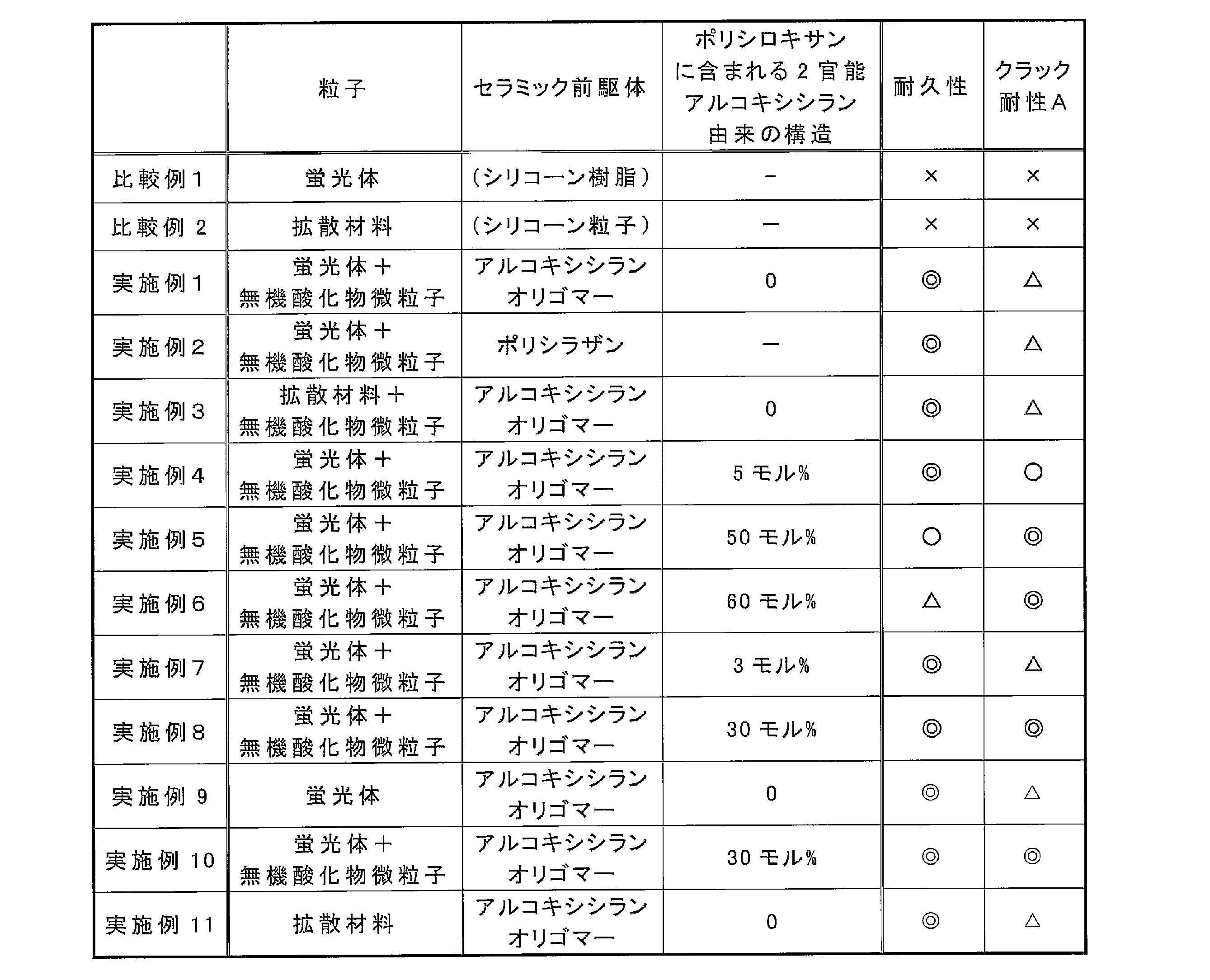
上記表1に示されるように、蛍光体または拡散材料を含み、かつセラミック前駆体を反応させて得られるセラミックバインダを含む光調整層では、耐久性が高く、かつ冷熱サイクルによっても、クラックが生じ難かった(実施例1~11)。また特に、セラミックバインダがポリシロキサンである場合に、2官能アルコキシシラン由来の構造が5モル%以上含まれると、光調整層のクラック耐性が高まりやすかった(実施例5、6、8、及び10)。光調整層の柔軟性が高まったため、クラックが生じ難くなったと推察される。ただし、2官能アルコキシシラン由来の構造が50モル%超含まれると、耐久性が若干低下した(実施例6)。2官能アルコキシシラン由来の構造に含まれる有機基の量が増えることで、膜が劣化しやすくなり、耐久性が低下したと推察される。
また、実施例1及び3の比較から、光調整層に含まれる粒子が、蛍光体である場合、及び拡散材料である場合の、いずれにおいても、同様の結果が得られることが示された。また、実施例8及び10の比較から、蛍光体及びアルコキシシランオリゴマーを分けて塗布した場合、及び一液で塗布した場合のいずれにおいても、同様の結果が得られることが示された。なお、蛍光体や拡散材料と共に、無機酸化物微粒子が含まれない場合には、クラック耐性が若干低下した(実施例9)。
一方、光調整層のバインダがシリコーン樹脂である場合には、耐久性が低く、クラック耐性も低かった(比較例1及び比較例2)。冷熱衝撃によってバインダにクラックが生じやすく、さらにレーザー光によってもバインダが劣化したと推察される。
[実施例12]
以下の粒子含有溶液を用いた以外は、実施例8と同様に光調整層を作製した。光調整層の厚みは、中心部及び端部ともに100μmとした。また、光調整層に含まれるポリシロキサンの構成単位中の2官能アルコキシシラン由来の構成単位の量を29Si-NMRで測定したところ、30モル%であった。
以下の粒子含有溶液を用いた以外は、実施例8と同様に光調整層を作製した。光調整層の厚みは、中心部及び端部ともに100μmとした。また、光調整層に含まれるポリシロキサンの構成単位中の2官能アルコキシシラン由来の構成単位の量を29Si-NMRで測定したところ、30モル%であった。
(粒子含有溶液の調製)
酸化ケイ素(RX300、日本アエロジル株式会社製、粒径7nm)4g、スメクタイト(ルーセンタイトSWN、コープケミカル社製)4g、及び緑色蛍光体(GAL545、Intematix社製)77g、をプロピレングリコール100g中に混合した。当該混合液にさらに酸化チタン(TA-100、富士チタン工業社製、粒径600nm)33gを混合した。
酸化ケイ素(RX300、日本アエロジル株式会社製、粒径7nm)4g、スメクタイト(ルーセンタイトSWN、コープケミカル社製)4g、及び緑色蛍光体(GAL545、Intematix社製)77g、をプロピレングリコール100g中に混合した。当該混合液にさらに酸化チタン(TA-100、富士チタン工業社製、粒径600nm)33gを混合した。
[実施例13]
粒子含有溶液中の酸化チタンの量を40gに変更した以外は、実施例12と同様に光調整層を得た。
粒子含有溶液中の酸化チタンの量を40gに変更した以外は、実施例12と同様に光調整層を得た。
[実施例14]
粒子含有溶液中の酸化チタンの量を63gに変更した以外は、実施例12と同様に光調整層を得た。
粒子含有溶液中の酸化チタンの量を63gに変更した以外は、実施例12と同様に光調整層を得た。
[実施例15]
粒子含有溶液中の酸化チタンの量を180gに変更した以外は、実施例12と同様に光調整層を得た。
粒子含有溶液中の酸化チタンの量を180gに変更した以外は、実施例12と同様に光調整層を得た。
[実施例16]
粒子含有溶液中の酸化チタンの量を230gに変更した以外は、実施例12と同様に光調整層を得た。
粒子含有溶液中の酸化チタンの量を230gに変更した以外は、実施例12と同様に光調整層を得た。
[実施例17]
以下の粒子含有溶液を用いた以外は、実施例14と同様に光調整層を得た。
以下の粒子含有溶液を用いた以外は、実施例14と同様に光調整層を得た。
(粒子含有溶液の調製)
緑色蛍光体(GAL545、Intematix社製)77g、酸化チタン(TA-100、富士チタン工業社製、粒径600nm)63gをプロピレングリコール100gに混合した。
緑色蛍光体(GAL545、Intematix社製)77g、酸化チタン(TA-100、富士チタン工業社製、粒径600nm)63gをプロピレングリコール100gに混合した。
[評価]
比較例1及び実施例8、12~17で作製した投射型表示装置用カラーホイールについて、以下の方法により、励起光の透過抑制性を評価した。結果を表2に示す。
比較例1及び実施例8、12~17で作製した投射型表示装置用カラーホイールについて、以下の方法により、励起光の透過抑制性を評価した。結果を表2に示す。
(励起光の透過抑制性評価)
各カラーホイールの光調整層の正面から、青色LEDにより光を照射した。そして、基板(ガラス基板)側から出射する青色光(波長460nmの光)の強度を測定した。測定装置は、コニカミノルタセンシング社製分光放射輝度計CS-1000Aとした。また、リファレンスとして、ガラス基板の一方の面の正面から青色LEDにより光を照射し、他方の面から出射する青色光(波長460nmの光)の強度を測定した。
各カラーホイールの光調整層の正面から、青色LEDにより光を照射した。そして、基板(ガラス基板)側から出射する青色光(波長460nmの光)の強度を測定した。測定装置は、コニカミノルタセンシング社製分光放射輝度計CS-1000Aとした。また、リファレンスとして、ガラス基板の一方の面の正面から青色LEDにより光を照射し、他方の面から出射する青色光(波長460nmの光)の強度を測定した。
各カラーホイールの光調整層には、青色光を受けて緑色光を出射する蛍光体が含まれている。つまり、当該カラーホイールは、緑色光を出射することが求められている。これに対し、光源からの光である青色光が光調整層を透過、つまり上記測定において基板側で青色光が観測されると、光調整層から出射する光に、緑色光だけでなく青色光も含まれてしまう。その結果、所望の緑色光が出射されないこととなる。
そこで、以下式で算出される強度比に基づき、励起光である青色光の透過度合いを評価した。評価は以下の基準とした。
強度比:各カラーホイールの基板側で測定される青色光の強度/リファレンスの青色光の強度×100
◎:上記強度比が3%未満
〇:上記強度比が3%以上5%未満
△:上記強度比が5%以上10%未満
×:上記強度比が10%以上
そこで、以下式で算出される強度比に基づき、励起光である青色光の透過度合いを評価した。評価は以下の基準とした。
強度比:各カラーホイールの基板側で測定される青色光の強度/リファレンスの青色光の強度×100
◎:上記強度比が3%未満
〇:上記強度比が3%以上5%未満
△:上記強度比が5%以上10%未満
×:上記強度比が10%以上
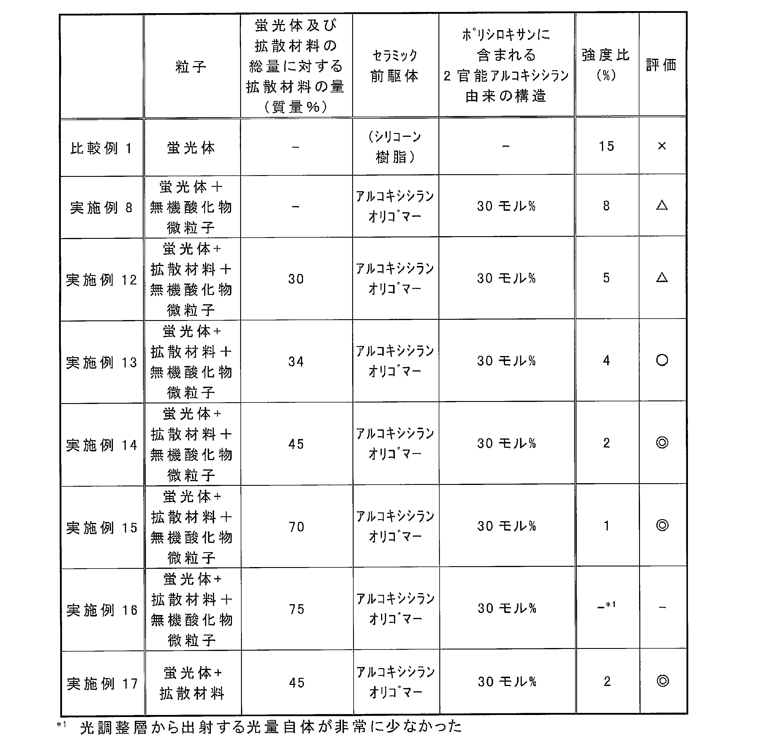
上記表2に示されるように、光調整層に拡散材料(酸化チタン)が含まれる場合には、励起光である青色光が光調整層を透過し難かった(実施例12~17)。ただし、拡散材料の量が過剰であると、光調整層から出射する光量が非常に小さくなった(実施例16)。拡散材料によって、蛍光体の励起光も遮蔽されてしまい、光量が小さくなったと推察される。
[比較例1b]
ガラス基板に、銀を厚み200nm蒸着し、当該基板上に光調整層を作製した以外は、比較例1と同様に投射型表示装置用カラーホイールを作製した。
ガラス基板に、銀を厚み200nm蒸着し、当該基板上に光調整層を作製した以外は、比較例1と同様に投射型表示装置用カラーホイールを作製した。
[実施例14b]
粒子含有溶液に酸化ケイ素、スメクタイト、及び酸化チタン(拡散材料)を添加せず、ガラス基板に、銀を厚み200nm蒸着し、当該基板上に光調整層を作製した以外は、実施例14と同様に投射型表示装置用カラーホイールを作製した。
粒子含有溶液に酸化ケイ素、スメクタイト、及び酸化チタン(拡散材料)を添加せず、ガラス基板に、銀を厚み200nm蒸着し、当該基板上に光調整層を作製した以外は、実施例14と同様に投射型表示装置用カラーホイールを作製した。
[実施例18]
セラミック前駆体含有組成物に、3-メルカプトプロピルメチルジメトキシシラン12.7gを混合した以外は実施例14bと同様に、投射型表示装置用カラーホイールを作製した。
セラミック前駆体含有組成物に、3-メルカプトプロピルメチルジメトキシシラン12.7gを混合した以外は実施例14bと同様に、投射型表示装置用カラーホイールを作製した。
[評価]
比較例1b、実施例14b、及び実施例18で作製した投射型表示装置用カラーホイールについて、以下の方法により、密着性を評価した。結果を表3に示す。
比較例1b、実施例14b、及び実施例18で作製した投射型表示装置用カラーホイールについて、以下の方法により、密着性を評価した。結果を表3に示す。
(密着性評価)
各ホイールを、温度60℃、湿度90%Rhの環境下に1000時間静置した。その後、カラーホイールの光調整層側の正面から50wの青色レーザーを1000h照射し、ガラス基板側から出射する光の輝度を測定した。その後、光調整層の表面を顕微鏡にて目視観察し、基板と光調整層との間に剥がれがあるか、確認した。
◎:全く剥がれ無し
〇:殆ど剥がれ無し
×:剥がれ有り
各ホイールを、温度60℃、湿度90%Rhの環境下に1000時間静置した。その後、カラーホイールの光調整層側の正面から50wの青色レーザーを1000h照射し、ガラス基板側から出射する光の輝度を測定した。その後、光調整層の表面を顕微鏡にて目視観察し、基板と光調整層との間に剥がれがあるか、確認した。
◎:全く剥がれ無し
〇:殆ど剥がれ無し
×:剥がれ有り

表3に示されるように、光調整層のバインダがポリシロキサンである場合(実施例14b及び18)には、基板と光調整層との密着性が高まった。ポリシロキサン中のSiと、基板表面のOH基等とがSi-O結合を形成するため、基板と光調整層との密着性が高まったと推察される。またさらに、光調整層形成時に、メルカプト基含有シランカップリング剤が添加されると、基板と光調整層との密着性が高まり、光調整層が非常に剥離し難かった。
[実施例19]
スプレー装置のノズルと基板との距離を30mmとし、さらに塗布速度(基板とスプレー装置との相対速度)を100mm/sとした以外は、実施例14と同様に光調整層を形成した。得られた光調整層の端部の厚みは、中心部の厚み(100μm)に対して、50%(50μm)であった。
スプレー装置のノズルと基板との距離を30mmとし、さらに塗布速度(基板とスプレー装置との相対速度)を100mm/sとした以外は、実施例14と同様に光調整層を形成した。得られた光調整層の端部の厚みは、中心部の厚み(100μm)に対して、50%(50μm)であった。
[実施例20]
スプレー装置のノズルと基板との距離を70mmとし、さらに塗布速度(基板とスプレー装置との相対速度)を70mm/sとした以外は、実施例14と同様に光調整層を形成した。得られた光調整層の端部の厚みは、中心部の厚み(100μm)に対して、70%(70μm)であった。
スプレー装置のノズルと基板との距離を70mmとし、さらに塗布速度(基板とスプレー装置との相対速度)を70mm/sとした以外は、実施例14と同様に光調整層を形成した。得られた光調整層の端部の厚みは、中心部の厚み(100μm)に対して、70%(70μm)であった。
[実施例21]
スプレー装置のノズルと基板との距離を50mmとし、さらに塗布速度(基板とスプレー装置との相対速度)を85mm/sとした以外は、実施例14と同様に光調整層を形成した。得られた光調整層の端部の厚みは、中心部の厚み(100μm)に対して、60%(60μm)であった。
スプレー装置のノズルと基板との距離を50mmとし、さらに塗布速度(基板とスプレー装置との相対速度)を85mm/sとした以外は、実施例14と同様に光調整層を形成した。得られた光調整層の端部の厚みは、中心部の厚み(100μm)に対して、60%(60μm)であった。
[評価]
実施例14、及び19~21で作製した投射型表示装置用カラーホイールについて、以下の方法によりクラック耐性を評価した。結果を表4に示す。
実施例14、及び19~21で作製した投射型表示装置用カラーホイールについて、以下の方法によりクラック耐性を評価した。結果を表4に示す。
(クラック耐性評価B)
ヒートショック試験機を用いて、光調整層のクラック耐性を調整した。具体的には、-40℃で30分間、125℃で30分間を1サイクルとし、1000サイクル行った。当該サイクルを行ったときのクラック発生状況を、顕微鏡にて目視観察した。そして、以下の基準で評価した。
◎:クラック無し
〇:目視で確認できない程度のわずかなクラックが発生
△:目視で確認できる程度のクラックが発生しているが、実用上問題なし
×:目視で確認できる程度のクラックが発生しており、実用上問題あり
ヒートショック試験機を用いて、光調整層のクラック耐性を調整した。具体的には、-40℃で30分間、125℃で30分間を1サイクルとし、1000サイクル行った。当該サイクルを行ったときのクラック発生状況を、顕微鏡にて目視観察した。そして、以下の基準で評価した。
◎:クラック無し
〇:目視で確認できない程度のわずかなクラックが発生
△:目視で確認できる程度のクラックが発生しているが、実用上問題なし
×:目視で確認できる程度のクラックが発生しており、実用上問題あり
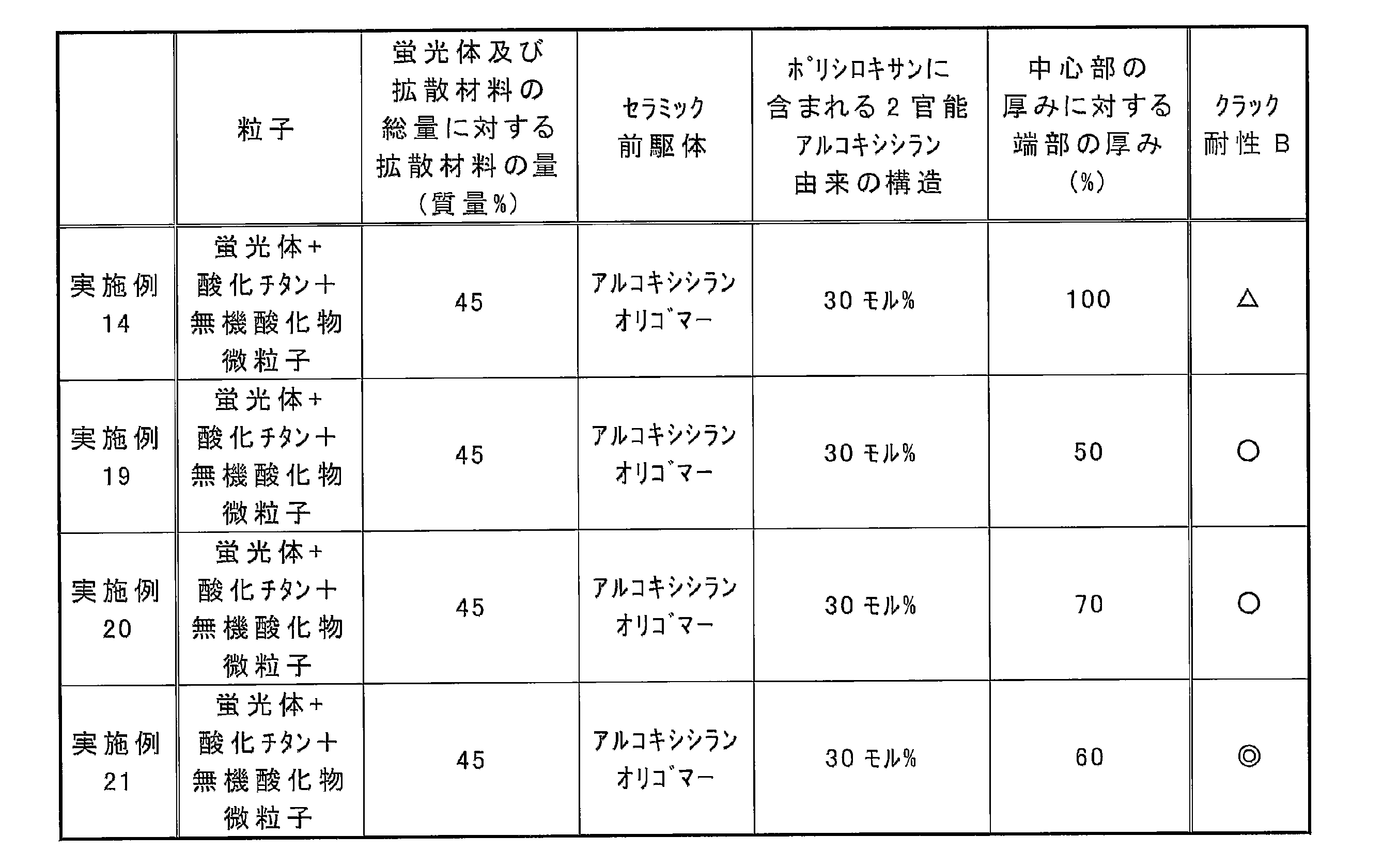
表4に示されるように、平坦な形状の光調整層を有する実施例14より、中心部の厚みに対して端部の厚みが薄い光調整層を有する実施例19~21では、クラック耐性が高まりやすかった。光調整層の厚みが端部で薄くなると、光調整層の成膜時に生じる歪みが緩和されやすく、さらに冷熱サイクル時にかかる応力も緩和されやすくなると推察される。
本出願は、2015年1月30日出願の特願2015-017343号に基づく優先権を主張する。当該出願明細書および図面に記載された内容は、すべて本願明細書に援用される。
本発明の投射型表示装置用カラーホイールは、長期間使用しても、光調整層が着色し難く、さらに蛍光体や拡散材料の脱落も少ない。したがって、各種投射型表示装置に適用可能である。
1 基板
2 光調整層
100 投射型表示装置用カラーホイール
2 光調整層
100 投射型表示装置用カラーホイール
Claims (12)
- 基板と、
前記基板上に形成され、セラミック前駆体の反応物からなるセラミックバインダ、並びに、蛍光体及び拡散材料のうち少なくとも一方を含む光調整層と、
を有する、投射型表示装置用カラーホイール。 - 前記セラミック前駆体が、ポリシラザン、アルコキシシランモノマー、及びアルコキシシランオリゴマーからなる群から選ばれる一種以上のポリシロキサン前駆体である、請求項1に記載の投射型表示装置用カラーホイール。
- 前記セラミックバインダが、ポリシロキサンを含み、かつ
前記ポリシロキサンの全構成単位中に、2官能アルコキシシラン由来の構成単位を5~50モル%含む、請求項1または2に記載の投射型表示装置用カラーホイール。 - 前記拡散材料が、酸化チタン、酸化ケイ素、硫酸バリウム、チタン酸バリウム、窒化ホウ素、酸化亜鉛、及び酸化アルミニウムからなる群から選ばれる一種以上の無機化合物からなり、かつ平均一次粒径が100nm~10μmの粒子である、請求項1~3のいずれか一項に記載の投射型表示装置用カラーホイール。
- 前記光調整層が、前記拡散材料及び前記蛍光体を含み、かつ
前記蛍光体及び前記拡散材料の総量に対して、前記拡散材料を34質量%以上70質量%未満含む、請求項1~4のいずれか一項に記載の投射型表示装置用カラーホイール。 - 前記基板が、少なくとも、前記光調整層と隣接する面に金属からなる金属反射面を有し、
前記光調整層が、メルカプト基含有カップリング剤由来の構造を含む、請求項1~5のいずれか一項に記載の投射型表示装置用カラーホイール。 - 前記光調整層は、端部の厚みが中心部の厚みより薄く、
前記中心部の厚みに対する、前記端部の厚みが50~70%である、請求項1~6のいずれか一項に記載の投射型表示装置用カラーホイール。 - 請求項1~7のいずれか一項に記載の投射型表示装置用カラーホイールの製造方法であって、
前記蛍光体及び前記拡散材料のうち少なくとも一方と、溶媒と、を含む粒子含有溶液を前記基板上に塗布し、乾燥させて粒子含有膜を得る工程と、
前記セラミック前駆体を含むセラミック前駆体含有組成物を、前記粒子含有膜上に塗布し、加熱硬化させ前記光調整層を形成する工程と、
を含む投射型表示装置用カラーホイールの製造方法。 - 請求項1~7のいずれか一項に記載の投射型表示装置用カラーホイールの製造方法であって、
前記蛍光体及び前記拡散材料のうち少なくとも一方と、前記セラミック前駆体と、を含む光調整層形成用組成物を前記基板上に塗布し、加熱硬化させ前記光調整層を形成する工程を含む投射型表示装置用カラーホイールの製造方法。 - 前記セラミック前駆体含有組成物、または前記光調整層形成用組成物を、スプレーまたはディスペンサーで塗布する、請求項8または9に記載の投射型表示装置用カラーホイールの製造方法。
- 前記基板を回転させながら、前記セラミック前駆体含有組成物または前記光調整層形成用組成物を、スプレーで塗布する、請求項8または9に記載の投射型表示装置用カラーホイールの製造方法。
- 請求項1~7のいずれか一項に記載の投射型表示装置用カラーホイールを含む、投射型表示装置。
Priority Applications (1)
| Application Number | Priority Date | Filing Date | Title |
|---|---|---|---|
| JP2016572131A JPWO2016121855A1 (ja) | 2015-01-30 | 2016-01-28 | 投射型表示装置用カラーホイール及びその製造方法、並びにこれを含む投射型表示装置 |
Applications Claiming Priority (2)
| Application Number | Priority Date | Filing Date | Title |
|---|---|---|---|
| JP2015-017343 | 2015-01-30 | ||
| JP2015017343 | 2015-01-30 |
Publications (1)
| Publication Number | Publication Date |
|---|---|
| WO2016121855A1 true WO2016121855A1 (ja) | 2016-08-04 |
Family
ID=56543460
Family Applications (1)
| Application Number | Title | Priority Date | Filing Date |
|---|---|---|---|
| PCT/JP2016/052454 Ceased WO2016121855A1 (ja) | 2015-01-30 | 2016-01-28 | 投射型表示装置用カラーホイール及びその製造方法、並びにこれを含む投射型表示装置 |
Country Status (2)
| Country | Link |
|---|---|
| JP (1) | JPWO2016121855A1 (ja) |
| WO (1) | WO2016121855A1 (ja) |
Cited By (13)
| Publication number | Priority date | Publication date | Assignee | Title |
|---|---|---|---|---|
| JP2017215568A (ja) * | 2016-05-31 | 2017-12-07 | キヤノン株式会社 | 波長変換素子、光源装置および画像投射装置 |
| JP2018189927A (ja) * | 2017-05-11 | 2018-11-29 | パナソニックIpマネジメント株式会社 | 蛍光体ホイール |
| WO2019107100A1 (ja) * | 2017-11-30 | 2019-06-06 | マクセル株式会社 | 蛍光体部材及び光源装置 |
| CN110575927A (zh) * | 2019-08-26 | 2019-12-17 | 广东联大光电有限公司 | 一种荧光粉色轮自动涂覆设备 |
| JPWO2018159268A1 (ja) * | 2017-03-02 | 2019-12-19 | パナソニックIpマネジメント株式会社 | 波長変換部材、光源及び照明装置 |
| US10775686B2 (en) | 2016-05-31 | 2020-09-15 | Canon Kabushiki Kaisha | Wavelength conversion element, light source apparatus and image projection apparatus |
| JPWO2020213726A1 (ja) * | 2019-04-18 | 2020-10-22 | ||
| CN112180663A (zh) * | 2019-07-04 | 2021-01-05 | 肖特股份有限公司 | 光转换轮 |
| WO2021256386A1 (ja) | 2020-06-15 | 2021-12-23 | 日産化学株式会社 | 積層体、剥離剤組成物及び加工された半導体基板の製造方法 |
| JP2022007638A (ja) * | 2020-06-26 | 2022-01-13 | 日亜化学工業株式会社 | 成形体、発光装置及び成形体の製造方法 |
| JP2022174143A (ja) * | 2017-08-08 | 2022-11-22 | パナソニックIpマネジメント株式会社 | 蛍光板、光源装置、及び投写型映像表示装置 |
| WO2024162024A1 (ja) * | 2023-01-31 | 2024-08-08 | パナソニックIpマネジメント株式会社 | 蛍光体ホイール及びその製造方法 |
| US12313869B2 (en) | 2020-10-13 | 2025-05-27 | Nippon Sheet Glass Company, Limited | Optical filter, optical device, and light-absorbing composition |
Citations (8)
| Publication number | Priority date | Publication date | Assignee | Title |
|---|---|---|---|---|
| JP2009251190A (ja) * | 2008-04-03 | 2009-10-29 | Fujifilm Corp | 光学フィルム、偏光板、画像表示装置 |
| JP2010129184A (ja) * | 2008-11-25 | 2010-06-10 | Sumitomo Osaka Cement Co Ltd | 有機el素子 |
| WO2013046662A1 (ja) * | 2011-09-26 | 2013-04-04 | コニカミノルタアドバンストレイヤー株式会社 | Led装置 |
| JP2013073063A (ja) * | 2011-09-28 | 2013-04-22 | Casio Comput Co Ltd | 蛍光体ホイール、光源装置及びプロジェクター |
| JP2013073217A (ja) * | 2011-09-29 | 2013-04-22 | Casio Comput Co Ltd | 蛍光体デバイス、照明装置及びプロジェクタ装置 |
| JP2014508815A (ja) * | 2010-12-07 | 2014-04-10 | コーニンクレッカ フィリップス エヌ ヴェ | カラーリングの一部分を製造する方法及びカラーリングの一部分 |
| WO2014119561A1 (ja) * | 2013-01-29 | 2014-08-07 | 富士フイルム株式会社 | 電飾用シート、電飾用印刷物およびその製造方法ならびに電飾看板 |
| WO2014174560A1 (ja) * | 2013-04-22 | 2014-10-30 | 日立マクセル株式会社 | 光源装置及び投写型映像表示装置 |
-
2016
- 2016-01-28 WO PCT/JP2016/052454 patent/WO2016121855A1/ja not_active Ceased
- 2016-01-28 JP JP2016572131A patent/JPWO2016121855A1/ja active Pending
Patent Citations (8)
| Publication number | Priority date | Publication date | Assignee | Title |
|---|---|---|---|---|
| JP2009251190A (ja) * | 2008-04-03 | 2009-10-29 | Fujifilm Corp | 光学フィルム、偏光板、画像表示装置 |
| JP2010129184A (ja) * | 2008-11-25 | 2010-06-10 | Sumitomo Osaka Cement Co Ltd | 有機el素子 |
| JP2014508815A (ja) * | 2010-12-07 | 2014-04-10 | コーニンクレッカ フィリップス エヌ ヴェ | カラーリングの一部分を製造する方法及びカラーリングの一部分 |
| WO2013046662A1 (ja) * | 2011-09-26 | 2013-04-04 | コニカミノルタアドバンストレイヤー株式会社 | Led装置 |
| JP2013073063A (ja) * | 2011-09-28 | 2013-04-22 | Casio Comput Co Ltd | 蛍光体ホイール、光源装置及びプロジェクター |
| JP2013073217A (ja) * | 2011-09-29 | 2013-04-22 | Casio Comput Co Ltd | 蛍光体デバイス、照明装置及びプロジェクタ装置 |
| WO2014119561A1 (ja) * | 2013-01-29 | 2014-08-07 | 富士フイルム株式会社 | 電飾用シート、電飾用印刷物およびその製造方法ならびに電飾看板 |
| WO2014174560A1 (ja) * | 2013-04-22 | 2014-10-30 | 日立マクセル株式会社 | 光源装置及び投写型映像表示装置 |
Cited By (22)
| Publication number | Priority date | Publication date | Assignee | Title |
|---|---|---|---|---|
| US10775686B2 (en) | 2016-05-31 | 2020-09-15 | Canon Kabushiki Kaisha | Wavelength conversion element, light source apparatus and image projection apparatus |
| JP2017215568A (ja) * | 2016-05-31 | 2017-12-07 | キヤノン株式会社 | 波長変換素子、光源装置および画像投射装置 |
| JPWO2018159268A1 (ja) * | 2017-03-02 | 2019-12-19 | パナソニックIpマネジメント株式会社 | 波長変換部材、光源及び照明装置 |
| JP2018189927A (ja) * | 2017-05-11 | 2018-11-29 | パナソニックIpマネジメント株式会社 | 蛍光体ホイール |
| JP2022174143A (ja) * | 2017-08-08 | 2022-11-22 | パナソニックIpマネジメント株式会社 | 蛍光板、光源装置、及び投写型映像表示装置 |
| JP7417811B2 (ja) | 2017-08-08 | 2024-01-19 | パナソニックIpマネジメント株式会社 | 蛍光板、光源装置、及び投写型映像表示装置 |
| WO2019107100A1 (ja) * | 2017-11-30 | 2019-06-06 | マクセル株式会社 | 蛍光体部材及び光源装置 |
| JPWO2020213726A1 (ja) * | 2019-04-18 | 2020-10-22 | ||
| CN113677687A (zh) * | 2019-04-18 | 2021-11-19 | 日本板硝子株式会社 | 光吸收性组合物和滤光器 |
| US12287503B2 (en) | 2019-04-18 | 2025-04-29 | Nippon Sheet Glass Company, Limited | Light-absorbing composition and optical filter |
| JP7629395B2 (ja) | 2019-04-18 | 2025-02-13 | 日本板硝子株式会社 | 光吸収性組成物及び光学フィルタ |
| TWI902690B (zh) * | 2019-04-18 | 2025-11-01 | 日商日本板硝子股份有限公司 | 光吸收性組成物及濾光器 |
| CN112180663A (zh) * | 2019-07-04 | 2021-01-05 | 肖特股份有限公司 | 光转换轮 |
| CN110575927B (zh) * | 2019-08-26 | 2024-08-20 | 广东联大光电有限公司 | 一种荧光粉色轮自动涂覆设备 |
| CN110575927A (zh) * | 2019-08-26 | 2019-12-17 | 广东联大光电有限公司 | 一种荧光粉色轮自动涂覆设备 |
| WO2021256386A1 (ja) | 2020-06-15 | 2021-12-23 | 日産化学株式会社 | 積層体、剥離剤組成物及び加工された半導体基板の製造方法 |
| US12297381B2 (en) | 2020-06-15 | 2025-05-13 | Nissan Chemical Corporation | Laminate, release agent composition, and method for manufacturing processed semiconductor substrate |
| JP2022007638A (ja) * | 2020-06-26 | 2022-01-13 | 日亜化学工業株式会社 | 成形体、発光装置及び成形体の製造方法 |
| JP7678270B2 (ja) | 2020-06-26 | 2025-05-16 | 日亜化学工業株式会社 | 成形体、発光装置及び成形体の製造方法 |
| US12313869B2 (en) | 2020-10-13 | 2025-05-27 | Nippon Sheet Glass Company, Limited | Optical filter, optical device, and light-absorbing composition |
| JPWO2024162024A1 (ja) * | 2023-01-31 | 2024-08-08 | ||
| WO2024162024A1 (ja) * | 2023-01-31 | 2024-08-08 | パナソニックIpマネジメント株式会社 | 蛍光体ホイール及びその製造方法 |
Also Published As
| Publication number | Publication date |
|---|---|
| JPWO2016121855A1 (ja) | 2017-11-09 |
Similar Documents
| Publication | Publication Date | Title |
|---|---|---|
| WO2016121855A1 (ja) | 投射型表示装置用カラーホイール及びその製造方法、並びにこれを含む投射型表示装置 | |
| EP2940743A1 (en) | Light emitting device | |
| US9708492B2 (en) | LED device and coating liquid used for production of same | |
| JP5843016B2 (ja) | Led装置及びその製造方法 | |
| JP2014158011A (ja) | Led装置の製造方法 | |
| JPWO2013099193A1 (ja) | Led装置用封止剤、led装置、及びled装置の製造方法 | |
| JP2014130871A (ja) | 発光装置 | |
| JP2019522818A (ja) | ポリシロキサン材料を有する波長変換体、その製造方法、およびそれを含有する固体照明装置 | |
| WO2013051280A1 (ja) | 蛍光体分散液、及びこれを用いたled装置の製造方法 | |
| JP5910340B2 (ja) | Led装置、及びその製造方法 | |
| JP2014135400A (ja) | 発光装置及び波長変換素子 | |
| WO2014027460A1 (ja) | 蛍光体分散液の製造方法、及びled装置の製造方法 | |
| JP2014138081A (ja) | 発光装置、波長変換・光拡散素子及びそれらの製造方法、光拡散セラミック層形成用組成物 | |
| WO2014030342A1 (ja) | Led装置及びその製造方法 | |
| JP2014130903A (ja) | 半導体発光装置及びその製造方法 | |
| JP2014127495A (ja) | Led装置、及びその製造方法 | |
| WO2014103330A1 (ja) | 蛍光体分散液、led装置およびその製造方法 | |
| JP2014019844A (ja) | 蛍光体分散液及びled装置の製造方法 | |
| JP2016154179A (ja) | 発光装置、及びその製造方法 | |
| JPWO2013054658A1 (ja) | 波長変換素子及びその製造方法、発光装置及びその製造方法、混合液 | |
| JP2014041955A (ja) | Led装置、及びその製造方法 | |
| WO2013046662A1 (ja) | Led装置 | |
| JP2016181535A (ja) | 発光装置、および発光装置製造用の塗布液 | |
| JP2014160713A (ja) | Led装置の製造方法 | |
| JP5765428B2 (ja) | Led装置の製造方法 |
Legal Events
| Date | Code | Title | Description |
|---|---|---|---|
| 121 | Ep: the epo has been informed by wipo that ep was designated in this application |
Ref document number: 16743458 Country of ref document: EP Kind code of ref document: A1 |
|
| ENP | Entry into the national phase |
Ref document number: 2016572131 Country of ref document: JP Kind code of ref document: A |
|
| NENP | Non-entry into the national phase |
Ref country code: DE |
|
| 122 | Ep: pct application non-entry in european phase |
Ref document number: 16743458 Country of ref document: EP Kind code of ref document: A1 |