WO2016121744A1 - 磁性フィラー - Google Patents
磁性フィラー Download PDFInfo
- Publication number
- WO2016121744A1 WO2016121744A1 PCT/JP2016/052152 JP2016052152W WO2016121744A1 WO 2016121744 A1 WO2016121744 A1 WO 2016121744A1 JP 2016052152 W JP2016052152 W JP 2016052152W WO 2016121744 A1 WO2016121744 A1 WO 2016121744A1
- Authority
- WO
- WIPO (PCT)
- Prior art keywords
- ferrite particles
- particles
- ferrite
- resin
- outer shell
- Prior art date
Links
- 239000012762 magnetic filler Substances 0.000 title claims abstract description 31
- 239000002245 particle Substances 0.000 claims abstract description 280
- 229910000859 α-Fe Inorganic materials 0.000 claims abstract description 223
- 229920005989 resin Polymers 0.000 claims abstract description 62
- 239000011347 resin Substances 0.000 claims abstract description 62
- 238000011049 filling Methods 0.000 abstract description 5
- 239000011248 coating agent Substances 0.000 description 42
- 238000000576 coating method Methods 0.000 description 42
- 239000010936 titanium Substances 0.000 description 37
- 238000010304 firing Methods 0.000 description 28
- 239000011148 porous material Substances 0.000 description 24
- 230000005415 magnetization Effects 0.000 description 21
- 229910010413 TiO 2 Inorganic materials 0.000 description 19
- 238000005259 measurement Methods 0.000 description 18
- 239000002002 slurry Substances 0.000 description 15
- 238000000034 method Methods 0.000 description 14
- 230000002093 peripheral effect Effects 0.000 description 14
- 230000000052 comparative effect Effects 0.000 description 12
- 230000000694 effects Effects 0.000 description 12
- 239000011162 core material Substances 0.000 description 11
- 239000000843 powder Substances 0.000 description 11
- 239000002994 raw material Substances 0.000 description 11
- 239000000203 mixture Substances 0.000 description 9
- 238000002156 mixing Methods 0.000 description 8
- 239000012298 atmosphere Substances 0.000 description 6
- QVGXLLKOCUKJST-UHFFFAOYSA-N atomic oxygen Chemical compound [O] QVGXLLKOCUKJST-UHFFFAOYSA-N 0.000 description 6
- 239000011230 binding agent Substances 0.000 description 6
- 239000010419 fine particle Substances 0.000 description 6
- 229910052749 magnesium Inorganic materials 0.000 description 6
- 239000001301 oxygen Substances 0.000 description 6
- 229910052760 oxygen Inorganic materials 0.000 description 6
- 239000000243 solution Substances 0.000 description 6
- 229910052719 titanium Inorganic materials 0.000 description 6
- 239000011258 core-shell material Substances 0.000 description 5
- 238000010438 heat treatment Methods 0.000 description 5
- QSHDDOUJBYECFT-UHFFFAOYSA-N mercury Chemical compound [Hg] QSHDDOUJBYECFT-UHFFFAOYSA-N 0.000 description 5
- 229910052753 mercury Inorganic materials 0.000 description 5
- 238000002360 preparation method Methods 0.000 description 5
- 238000012545 processing Methods 0.000 description 5
- 229910052712 strontium Inorganic materials 0.000 description 5
- 150000001875 compounds Chemical class 0.000 description 4
- 238000001723 curing Methods 0.000 description 4
- 238000009826 distribution Methods 0.000 description 4
- 229910052742 iron Inorganic materials 0.000 description 4
- 229910052748 manganese Inorganic materials 0.000 description 4
- 239000012299 nitrogen atmosphere Substances 0.000 description 4
- 239000007787 solid Substances 0.000 description 4
- XLYOFNOQVPJJNP-UHFFFAOYSA-N water Substances O XLYOFNOQVPJJNP-UHFFFAOYSA-N 0.000 description 4
- 229910002593 Fe-Ti Inorganic materials 0.000 description 3
- 239000004962 Polyamide-imide Substances 0.000 description 3
- 239000011358 absorbing material Substances 0.000 description 3
- 238000001354 calcination Methods 0.000 description 3
- 239000007771 core particle Substances 0.000 description 3
- 238000004519 manufacturing process Methods 0.000 description 3
- 229920002312 polyamide-imide Polymers 0.000 description 3
- 238000004381 surface treatment Methods 0.000 description 3
- IJGRMHOSHXDMSA-UHFFFAOYSA-N Atomic nitrogen Chemical compound N#N IJGRMHOSHXDMSA-UHFFFAOYSA-N 0.000 description 2
- VEXZGXHMUGYJMC-UHFFFAOYSA-N Hydrochloric acid Chemical compound Cl VEXZGXHMUGYJMC-UHFFFAOYSA-N 0.000 description 2
- 239000006096 absorbing agent Substances 0.000 description 2
- 238000004458 analytical method Methods 0.000 description 2
- 239000000919 ceramic Substances 0.000 description 2
- 239000003795 chemical substances by application Substances 0.000 description 2
- 238000000635 electron micrograph Methods 0.000 description 2
- 239000012530 fluid Substances 0.000 description 2
- 238000005469 granulation Methods 0.000 description 2
- 230000003179 granulation Effects 0.000 description 2
- 230000005484 gravity Effects 0.000 description 2
- SZVJSHCCFOBDDC-UHFFFAOYSA-N iron(II,III) oxide Inorganic materials O=[Fe]O[Fe]O[Fe]=O SZVJSHCCFOBDDC-UHFFFAOYSA-N 0.000 description 2
- 229910052746 lanthanum Inorganic materials 0.000 description 2
- FZLIPJUXYLNCLC-UHFFFAOYSA-N lanthanum atom Chemical compound [La] FZLIPJUXYLNCLC-UHFFFAOYSA-N 0.000 description 2
- 238000000465 moulding Methods 0.000 description 2
- 238000010298 pulverizing process Methods 0.000 description 2
- 239000011342 resin composition Substances 0.000 description 2
- 239000007921 spray Substances 0.000 description 2
- OKTJSMMVPCPJKN-UHFFFAOYSA-N Carbon Chemical compound [C] OKTJSMMVPCPJKN-UHFFFAOYSA-N 0.000 description 1
- 229920000877 Melamine resin Polymers 0.000 description 1
- GRYLNZFGIOXLOG-UHFFFAOYSA-N Nitric acid Chemical compound O[N+]([O-])=O GRYLNZFGIOXLOG-UHFFFAOYSA-N 0.000 description 1
- VYPSYNLAJGMNEJ-UHFFFAOYSA-N Silicium dioxide Chemical compound O=[Si]=O VYPSYNLAJGMNEJ-UHFFFAOYSA-N 0.000 description 1
- RTAQQCXQSZGOHL-UHFFFAOYSA-N Titanium Chemical compound [Ti] RTAQQCXQSZGOHL-UHFFFAOYSA-N 0.000 description 1
- 229920001807 Urea-formaldehyde Polymers 0.000 description 1
- 230000001133 acceleration Effects 0.000 description 1
- NIXOWILDQLNWCW-UHFFFAOYSA-N acrylic acid group Chemical group C(C=C)(=O)O NIXOWILDQLNWCW-UHFFFAOYSA-N 0.000 description 1
- 239000000654 additive Substances 0.000 description 1
- 238000004220 aggregation Methods 0.000 description 1
- 230000002776 aggregation Effects 0.000 description 1
- 239000007864 aqueous solution Substances 0.000 description 1
- 239000011324 bead Substances 0.000 description 1
- 239000002775 capsule Substances 0.000 description 1
- 229910052799 carbon Inorganic materials 0.000 description 1
- 239000006229 carbon black Substances 0.000 description 1
- 239000003638 chemical reducing agent Substances 0.000 description 1
- 239000002131 composite material Substances 0.000 description 1
- 238000009833 condensation Methods 0.000 description 1
- 230000005494 condensation Effects 0.000 description 1
- 230000001186 cumulative effect Effects 0.000 description 1
- 230000006378 damage Effects 0.000 description 1
- 230000003247 decreasing effect Effects 0.000 description 1
- 230000007547 defect Effects 0.000 description 1
- 238000007872 degassing Methods 0.000 description 1
- 230000008021 deposition Effects 0.000 description 1
- 230000006866 deterioration Effects 0.000 description 1
- 239000002270 dispersing agent Substances 0.000 description 1
- 239000002612 dispersion medium Substances 0.000 description 1
- 239000003814 drug Substances 0.000 description 1
- 210000005069 ears Anatomy 0.000 description 1
- 238000000921 elemental analysis Methods 0.000 description 1
- 230000007613 environmental effect Effects 0.000 description 1
- 239000003822 epoxy resin Substances 0.000 description 1
- 238000001914 filtration Methods 0.000 description 1
- 230000004907 flux Effects 0.000 description 1
- 239000007789 gas Substances 0.000 description 1
- 239000007903 gelatin capsule Substances 0.000 description 1
- PCHJSUWPFVWCPO-UHFFFAOYSA-N gold Chemical compound [Au] PCHJSUWPFVWCPO-UHFFFAOYSA-N 0.000 description 1
- 229910052737 gold Inorganic materials 0.000 description 1
- 239000010931 gold Substances 0.000 description 1
- 238000000227 grinding Methods 0.000 description 1
- LNEPOXFFQSENCJ-UHFFFAOYSA-N haloperidol Chemical compound C1CC(O)(C=2C=CC(Cl)=CC=2)CCN1CCCC(=O)C1=CC=C(F)C=C1 LNEPOXFFQSENCJ-UHFFFAOYSA-N 0.000 description 1
- 238000013007 heat curing Methods 0.000 description 1
- 125000002887 hydroxy group Chemical group [H]O* 0.000 description 1
- 238000005470 impregnation Methods 0.000 description 1
- 238000009413 insulation Methods 0.000 description 1
- 239000007788 liquid Substances 0.000 description 1
- 239000006247 magnetic powder Substances 0.000 description 1
- 230000007257 malfunction Effects 0.000 description 1
- 238000013507 mapping Methods 0.000 description 1
- 229910052751 metal Inorganic materials 0.000 description 1
- 239000002184 metal Substances 0.000 description 1
- 239000002105 nanoparticle Substances 0.000 description 1
- 229910017604 nitric acid Inorganic materials 0.000 description 1
- 229910052757 nitrogen Inorganic materials 0.000 description 1
- 230000001590 oxidative effect Effects 0.000 description 1
- 239000008188 pellet Substances 0.000 description 1
- 239000005011 phenolic resin Substances 0.000 description 1
- 238000005498 polishing Methods 0.000 description 1
- 229920000647 polyepoxide Polymers 0.000 description 1
- 238000001878 scanning electron micrograph Methods 0.000 description 1
- 238000000790 scattering method Methods 0.000 description 1
- 238000004062 sedimentation Methods 0.000 description 1
- 229920002050 silicone resin Polymers 0.000 description 1
- 239000006104 solid solution Substances 0.000 description 1
- 239000002904 solvent Substances 0.000 description 1
- 238000001179 sorption measurement Methods 0.000 description 1
- 229910052596 spinel Inorganic materials 0.000 description 1
- 239000011029 spinel Substances 0.000 description 1
- 229910002076 stabilized zirconia Inorganic materials 0.000 description 1
- 229920005792 styrene-acrylic resin Polymers 0.000 description 1
- 239000000725 suspension Substances 0.000 description 1
- 238000010408 sweeping Methods 0.000 description 1
- 238000012360 testing method Methods 0.000 description 1
- 229910052725 zinc Inorganic materials 0.000 description 1
Images

Classifications
-
- H—ELECTRICITY
- H01—ELECTRIC ELEMENTS
- H01F—MAGNETS; INDUCTANCES; TRANSFORMERS; SELECTION OF MATERIALS FOR THEIR MAGNETIC PROPERTIES
- H01F1/00—Magnets or magnetic bodies characterised by the magnetic materials therefor; Selection of materials for their magnetic properties
- H01F1/01—Magnets or magnetic bodies characterised by the magnetic materials therefor; Selection of materials for their magnetic properties of inorganic materials
- H01F1/03—Magnets or magnetic bodies characterised by the magnetic materials therefor; Selection of materials for their magnetic properties of inorganic materials characterised by their coercivity
- H01F1/12—Magnets or magnetic bodies characterised by the magnetic materials therefor; Selection of materials for their magnetic properties of inorganic materials characterised by their coercivity of soft-magnetic materials
- H01F1/34—Magnets or magnetic bodies characterised by the magnetic materials therefor; Selection of materials for their magnetic properties of inorganic materials characterised by their coercivity of soft-magnetic materials non-metallic substances, e.g. ferrites
- H01F1/36—Magnets or magnetic bodies characterised by the magnetic materials therefor; Selection of materials for their magnetic properties of inorganic materials characterised by their coercivity of soft-magnetic materials non-metallic substances, e.g. ferrites in the form of particles
-
- C—CHEMISTRY; METALLURGY
- C08—ORGANIC MACROMOLECULAR COMPOUNDS; THEIR PREPARATION OR CHEMICAL WORKING-UP; COMPOSITIONS BASED THEREON
- C08K—Use of inorganic or non-macromolecular organic substances as compounding ingredients
- C08K3/00—Use of inorganic substances as compounding ingredients
- C08K3/18—Oxygen-containing compounds, e.g. metal carbonyls
- C08K3/20—Oxides; Hydroxides
- C08K3/22—Oxides; Hydroxides of metals
-
- C—CHEMISTRY; METALLURGY
- C01—INORGANIC CHEMISTRY
- C01G—COMPOUNDS CONTAINING METALS NOT COVERED BY SUBCLASSES C01D OR C01F
- C01G49/00—Compounds of iron
-
- C—CHEMISTRY; METALLURGY
- C01—INORGANIC CHEMISTRY
- C01G—COMPOUNDS CONTAINING METALS NOT COVERED BY SUBCLASSES C01D OR C01F
- C01G49/00—Compounds of iron
- C01G49/0018—Mixed oxides or hydroxides
- C01G49/0072—Mixed oxides or hydroxides containing manganese
-
- C—CHEMISTRY; METALLURGY
- C08—ORGANIC MACROMOLECULAR COMPOUNDS; THEIR PREPARATION OR CHEMICAL WORKING-UP; COMPOSITIONS BASED THEREON
- C08K—Use of inorganic or non-macromolecular organic substances as compounding ingredients
- C08K9/00—Use of pretreated ingredients
- C08K9/04—Ingredients treated with organic substances
-
- C—CHEMISTRY; METALLURGY
- C08—ORGANIC MACROMOLECULAR COMPOUNDS; THEIR PREPARATION OR CHEMICAL WORKING-UP; COMPOSITIONS BASED THEREON
- C08L—COMPOSITIONS OF MACROMOLECULAR COMPOUNDS
- C08L101/00—Compositions of unspecified macromolecular compounds
-
- H—ELECTRICITY
- H01—ELECTRIC ELEMENTS
- H01F—MAGNETS; INDUCTANCES; TRANSFORMERS; SELECTION OF MATERIALS FOR THEIR MAGNETIC PROPERTIES
- H01F1/00—Magnets or magnetic bodies characterised by the magnetic materials therefor; Selection of materials for their magnetic properties
- H01F1/01—Magnets or magnetic bodies characterised by the magnetic materials therefor; Selection of materials for their magnetic properties of inorganic materials
- H01F1/03—Magnets or magnetic bodies characterised by the magnetic materials therefor; Selection of materials for their magnetic properties of inorganic materials characterised by their coercivity
- H01F1/0302—Magnets or magnetic bodies characterised by the magnetic materials therefor; Selection of materials for their magnetic properties of inorganic materials characterised by their coercivity characterised by unspecified or heterogeneous hardness or specially adapted for magnetic hardness transitions
- H01F1/0311—Compounds
- H01F1/0313—Oxidic compounds
- H01F1/0315—Ferrites
-
- H—ELECTRICITY
- H01—ELECTRIC ELEMENTS
- H01F—MAGNETS; INDUCTANCES; TRANSFORMERS; SELECTION OF MATERIALS FOR THEIR MAGNETIC PROPERTIES
- H01F1/00—Magnets or magnetic bodies characterised by the magnetic materials therefor; Selection of materials for their magnetic properties
- H01F1/01—Magnets or magnetic bodies characterised by the magnetic materials therefor; Selection of materials for their magnetic properties of inorganic materials
- H01F1/03—Magnets or magnetic bodies characterised by the magnetic materials therefor; Selection of materials for their magnetic properties of inorganic materials characterised by their coercivity
- H01F1/032—Magnets or magnetic bodies characterised by the magnetic materials therefor; Selection of materials for their magnetic properties of inorganic materials characterised by their coercivity of hard-magnetic materials
- H01F1/10—Magnets or magnetic bodies characterised by the magnetic materials therefor; Selection of materials for their magnetic properties of inorganic materials characterised by their coercivity of hard-magnetic materials non-metallic substances, e.g. ferrites, e.g. [(Ba,Sr)O(Fe2O3)6] ferrites with hexagonal structure
- H01F1/11—Magnets or magnetic bodies characterised by the magnetic materials therefor; Selection of materials for their magnetic properties of inorganic materials characterised by their coercivity of hard-magnetic materials non-metallic substances, e.g. ferrites, e.g. [(Ba,Sr)O(Fe2O3)6] ferrites with hexagonal structure in the form of particles
- H01F1/112—Magnets or magnetic bodies characterised by the magnetic materials therefor; Selection of materials for their magnetic properties of inorganic materials characterised by their coercivity of hard-magnetic materials non-metallic substances, e.g. ferrites, e.g. [(Ba,Sr)O(Fe2O3)6] ferrites with hexagonal structure in the form of particles with a skin
-
- H—ELECTRICITY
- H01—ELECTRIC ELEMENTS
- H01F—MAGNETS; INDUCTANCES; TRANSFORMERS; SELECTION OF MATERIALS FOR THEIR MAGNETIC PROPERTIES
- H01F1/00—Magnets or magnetic bodies characterised by the magnetic materials therefor; Selection of materials for their magnetic properties
- H01F1/01—Magnets or magnetic bodies characterised by the magnetic materials therefor; Selection of materials for their magnetic properties of inorganic materials
- H01F1/03—Magnets or magnetic bodies characterised by the magnetic materials therefor; Selection of materials for their magnetic properties of inorganic materials characterised by their coercivity
- H01F1/12—Magnets or magnetic bodies characterised by the magnetic materials therefor; Selection of materials for their magnetic properties of inorganic materials characterised by their coercivity of soft-magnetic materials
- H01F1/34—Magnets or magnetic bodies characterised by the magnetic materials therefor; Selection of materials for their magnetic properties of inorganic materials characterised by their coercivity of soft-magnetic materials non-metallic substances, e.g. ferrites
- H01F1/36—Magnets or magnetic bodies characterised by the magnetic materials therefor; Selection of materials for their magnetic properties of inorganic materials characterised by their coercivity of soft-magnetic materials non-metallic substances, e.g. ferrites in the form of particles
- H01F1/37—Magnets or magnetic bodies characterised by the magnetic materials therefor; Selection of materials for their magnetic properties of inorganic materials characterised by their coercivity of soft-magnetic materials non-metallic substances, e.g. ferrites in the form of particles in a bonding agent
-
- C—CHEMISTRY; METALLURGY
- C01—INORGANIC CHEMISTRY
- C01G—COMPOUNDS CONTAINING METALS NOT COVERED BY SUBCLASSES C01D OR C01F
- C01G49/00—Compounds of iron
- C01G49/0018—Mixed oxides or hydroxides
-
- C—CHEMISTRY; METALLURGY
- C01—INORGANIC CHEMISTRY
- C01P—INDEXING SCHEME RELATING TO STRUCTURAL AND PHYSICAL ASPECTS OF SOLID INORGANIC COMPOUNDS
- C01P2004/00—Particle morphology
- C01P2004/60—Particles characterised by their size
- C01P2004/61—Micrometer sized, i.e. from 1-100 micrometer
-
- C—CHEMISTRY; METALLURGY
- C01—INORGANIC CHEMISTRY
- C01P—INDEXING SCHEME RELATING TO STRUCTURAL AND PHYSICAL ASPECTS OF SOLID INORGANIC COMPOUNDS
- C01P2006/00—Physical properties of inorganic compounds
- C01P2006/42—Magnetic properties
-
- C—CHEMISTRY; METALLURGY
- C08—ORGANIC MACROMOLECULAR COMPOUNDS; THEIR PREPARATION OR CHEMICAL WORKING-UP; COMPOSITIONS BASED THEREON
- C08K—Use of inorganic or non-macromolecular organic substances as compounding ingredients
- C08K3/00—Use of inorganic substances as compounding ingredients
- C08K3/18—Oxygen-containing compounds, e.g. metal carbonyls
- C08K3/20—Oxides; Hydroxides
- C08K3/22—Oxides; Hydroxides of metals
- C08K2003/2237—Oxides; Hydroxides of metals of titanium
- C08K2003/2241—Titanium dioxide
-
- C—CHEMISTRY; METALLURGY
- C08—ORGANIC MACROMOLECULAR COMPOUNDS; THEIR PREPARATION OR CHEMICAL WORKING-UP; COMPOSITIONS BASED THEREON
- C08K—Use of inorganic or non-macromolecular organic substances as compounding ingredients
- C08K3/00—Use of inorganic substances as compounding ingredients
- C08K3/18—Oxygen-containing compounds, e.g. metal carbonyls
- C08K3/20—Oxides; Hydroxides
- C08K3/22—Oxides; Hydroxides of metals
- C08K2003/2265—Oxides; Hydroxides of metals of iron
- C08K2003/2275—Ferroso-ferric oxide (Fe3O4)
Definitions
- the present invention relates to a magnetic filler, and more particularly to a magnetic filler composed of ferrite particles having a shell structure containing a Ti oxide and a resin molded body using the magnetic filler.
- Patent Document 1 Japanese Patent Application Laid-Open No. 5-299870 discloses a radio wave absorbing material for forming a magnetic layer to be laminated on a metal plate, and the magnetic layer is formed of spinel ferrite having a diameter of 0.5 ⁇ m to 5 mm.
- a radio wave absorbing material is described which is a layer having a thickness of 10 to 30 ⁇ m and containing 90 wt% or more of particles in a resin.
- (Mn, Zn) ferrite particles are exemplified as the ferrite particles.
- this Patent Document 2 describes using ferrite particles as a magnetic filler mixed with a resin.
- it has a low apparent density and has various properties. It is not possible to maintain a controllable state and fill a certain volume with a small weight. And the radio wave absorbing material described in the cited document 1 does not have sufficient radio wave shielding ability.
- Patent Document 2 Japanese Patent Laid-Open No. 2007-320847 includes a core fine particle structure including a plurality of primary fine particles and a plurality of primary pores, and a shell that at least partially surrounds the core fine particle structure.
- An article including a plurality of core-shell ceramic fine particles is described, and as the article, a film, a sensor, an electrode, and a getter are described.
- the core-shell ceramic fine particles described in Patent Document 2 are composed of yttrium-stabilized zirconia as a core and lanthanum ferrite as a shell. Since lanthanum ferrite is used as a shell, it has a low apparent density, It is not possible to fill a certain volume with a small weight while maintaining the characteristics in a controllable state.
- an object of the present invention is to use a magnetic filler composed of ferrite particles having a low apparent density, maintaining various properties in a controllable state, and being able to satisfy a certain volume with a small weight, and the magnetic filler. It is to provide a resin molded body.
- the present inventors can achieve the above object by using ferrite particles having an outer shell structure containing Ti oxide as a magnetic filler. As a result, the present invention has been achieved. The present invention has been made based on these findings.
- the present invention provides a magnetic filler characterized by comprising ferrite particles having an outer shell structure containing Ti oxide.
- the ferrite particles of the magnetic filler according to the present invention preferably have a thickness of a portion having the outer shell structure of 0.5 to 10 ⁇ m.
- the ferrite particles of the magnetic filler according to the present invention preferably have a density inside the particles lower than the density of the outer shell structure.
- the volume average particle size of the ferrite particles of the magnetic filler according to the present invention is preferably 10 to 100 ⁇ m.
- the ferrite particles are coated and / or impregnated with a resin.
- the present invention also provides a resin molded body using the magnetic filler.
- the ferrite particles according to the present invention have a low apparent density by having an outer shell structure containing Ti, and can satisfy a certain volume with a small weight while maintaining various characteristics in a controllable state. . Therefore, by using the ferrite particles as a magnetic filler, a low specific gravity molded resin can be obtained, and can be used for applications such as a radio wave absorber.
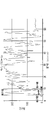
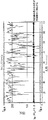
- the graph which image-analyzed the image obtained by FIG. The electron micrograph of FIG. 1 which shows the method to measure the outer peripheral part of the part which has an outer shell structure.
- the ferrite particles according to the present invention have an outer shell structure (core shell shape) containing titanium. This has a low apparent density and can maintain various properties in a controllable state. Further, the ferrite particles according to the present invention can fill the ferrite particles with a small weight in a constant volume.
- the term “ferrite particles” means an aggregate of individual ferrite particles unless otherwise specified, and the term simply refers to individual ferrite particles.
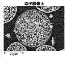
- the outer shell structure here means that the outer shell structure is formed to such an extent that it can be visually recognized in the cross-sectional SEM image when the cross-section is observed using the SEM after embedding the ferrite particles in the resin. is required. More specifically, the outer peripheral portion having a certain range of thickness has 80% or more of the peripheral length of the particle. More preferably, the ratio of the outer peripheral portion to the peripheral length is 90% or more.
- the thickness of the outer shell structure is preferably 0.5 to 10 ⁇ m, and the intended purpose can be achieved in this range. If the thickness of the outer shell structure is less than 0.5 ⁇ m, the mechanical strength of the ferrite particles is weak, and various powder characteristics originally possessed by destruction may not be exhibited. In particular, it may crack when used as a carrier and cause scratches on the photosensitive drum. If the thickness of the outer shell structure exceeds 10 ⁇ m, it is not different from conventional ferrite particles, and therefore the desired effect cannot be exhibited even if the outer shell structure is provided.
- the thickness of the outer shell structure is more preferably 0.5 to 8 ⁇ m, and most preferably 0.5 to 6.5 ⁇ m.
- the thickness of the outer shell structure is measured by embedding ferrite particles in a resin, observing a cross section using an SEM, as shown in FIGS.
- the obtained image can be measured by image processing.
- the thickness of the outer shell structure of the particles is measured according to the following procedure. After embedding and forming the ferrite particles in a resin, the cross section was polished with a polishing machine, and gold deposition was performed to obtain a sample for cross-sectional observation (for measuring the thickness of the outer shell).
- the sample obtained was JSM-6060A manufactured by JEOL Ltd., the acceleration voltage was 5 kV, SEM was photographed with a 200 ⁇ field of view, and the image information was image analysis software (Image- Pro PLUS) for analysis. Specifically, after adjusting the contrast of the obtained image, the luminance of the image is extracted for each particle by the line profile function of this analysis software.
- the line profile is set to a straight line so as to pass almost the center of the particle in the horizontal direction, and among the peaks existing in the obtained profile, the peak corresponding to the outer shell is sandwiched between two markers, and the width at this time Is the thickness of the outer shell.
- the peak is defined as a minimum value and a minimum value sandwiching the maximum value of the line profile.
- the contrast is preferably adjusted so that the luminance of the embedded resin portion (corresponding to the background) is 50% or less of the maximum luminance. The same operation was similarly performed on 30 particles, and the average value was defined as the thickness of the outer shell structure.
- the ratio of the outer peripheral portion to the peripheral length of the outer shell structure is as described in detail below.
- the line profile length of the luminance data obtained by the line profile function the line profile length of the luminance that is I minimum + I ⁇ ⁇ 0.2 or more and I maximum or less is integrated to obtain the line profile.
- the line profile is set to a straight line, and each particle is set to pass near the center of the particle.
- the maximum the maximum luminance profile I the minimum luminance is I minimum, when the difference between the maximum luminance and the minimum luminance was I delta, I minimum or more, I Min + I delta ⁇ range below 0.2 ferrite portion
- the portion where there is no ferrite, I minimum + I ⁇ ⁇ 0.2 or more and I maximum or less is determined as the portion where the ferrite exists.
- the line profile length (straight line) luminance data obtained by the line profile function the line profile length of the luminance that is I minimum + I ⁇ ⁇ 0.2 or more and I maximum or less is integrated, and the line profile length By dividing by (straight line), it can be obtained by calculating the ratio of the ferrite portion inside the particle. The same operation was performed on 30 particles, and the average value was defined as the density inside the particles.
- the low apparent density of conventional ferrite particles is achieved mainly by making the ferrite particles porous.
- the porous structure is characterized by the fact that it can be easily carried out by changing the firing conditions during the main firing.
- pores unique to the porous structure are uniformly generated from the surface to the inside. Therefore, when performing characteristic control by resin coating or resin impregnation, since a large amount of resin is present on the surface of the particles, the influence of the resin coated or impregnated is large, making it difficult to control the characteristics.
- the shape of the ferrite particle according to the present invention is a conventional granular particle, but the density of the particle is different between the part having the outer shell structure (outer shell part) and the inside of the particle having the porous structure. . More specifically, the pore volume of the particles is large because the density inside the particles is low, and the pore diameter is large because the density of the outer shell is high. Moreover, since it has an outer shell structure, it has a low apparent density compared to a conventional porous core. In addition, since the outer and inner sides of the ferrite particles are connected by localized pores, the resin and functional nanoparticles are dispersed inside the particles while maintaining the exposed surface of the ferrite particles while maintaining a low apparent density. Since the suspension can be impregnated, it becomes possible to have different functions in the outer shell portion and the inner porous portion, and new characteristics that could not be obtained with conventional ferrite particles can be acquired. It becomes like this.
- the ferrite particles according to the present invention preferably contain 0.5 to 4% by weight of Mg and 3 to 20% by weight of Mn.
- the ferrite particles according to the present invention preferably contain 47 to 70% by weight of Fe.
- the ferrite particles according to the present invention preferably contain 0.5 to 4.5% by weight of Ti.
- the ferrite particles according to the present invention contain Mg so that the magnetization can be easily adjusted. If Mg is less than 0.5% by weight, the effect of addition is weak and the magnetization cannot be controlled sufficiently. When the amount is more than 4% by weight, the magnetization becomes low, and it becomes difficult to use in an application utilizing the magnetic characteristics.
- the magnetization and resistance even when the ferrite particles according to the present invention contain Mn. If Mn is less than 3% by weight, the effect of addition is weak and the magnetization cannot be controlled sufficiently. When the amount is more than 20% by weight, Mn close to the stoichiometric ratio of Mn ferrite is contained, so that the inclusion effect is reduced and there is no meaning to contain. Further, by containing Mn, the magnetization can be controlled at the firing temperature even if the oxygen concentration is constant.
- the firing temperature can be controlled with high accuracy. That is, the rough magnetization control of the ferrite particles is performed by the Mg content, and the relationship between the firing temperature and the magnetization can be controlled in more detail by the Mn content.
- the ferrite particles contain Mg, so that a developer having a good rise in charge composed of a ferrite carrier using ferrite particles and a full-color toner can be obtained. .
- the resistance can be increased. If the Mg content is less than 0.5% by weight, a sufficient content effect cannot be obtained, the resistance becomes low, and the image quality deteriorates, such as generation of fog and deterioration of gradation.
- the magnetization becomes too high, so that the ears of the magnetic brush become hard and cause image defects such as scissors.
- the Mg content exceeds 4% by weight, not only ferrite carrier scattering occurs due to a decrease in magnetization, but when the firing temperature is low, the moisture adsorption amount is large due to the influence of hydroxyl groups due to Mg. As a result, the environmental dependency of the electrical characteristics such as the charge amount and the resistance is deteriorated.
- the Fe content in the ferrite particles according to the present invention is less than 47% by weight, the outer shell structure is not formed. On the other hand, if the Fe content exceeds 70% by weight, the Mg-containing effect cannot be obtained, and the ferrite particles are substantially equivalent to magnetite.
- the ferrite particles according to the present invention preferably contain 0.5 to 4.5% by weight of Ti.
- Ti has the effect of lowering the firing temperature and can not only reduce aggregated particles but also obtain a uniform and wrinkled surface property.
- the content of Ti in the ferrite particles is less than 0.5% by weight, the effect of containing Ti cannot be obtained, and particles having an outer shell structure cannot be obtained. Further, even if the Ti content exceeds 4.5% by weight, the core-shell particles are produced, but this is not preferable because it is difficult to use in applications using the magnetic properties of ferrite particles.
- the difference between the Ti content of the ferrite particles according to the present invention and the Ti content of the ferrite particles having no outer shell structure, that is, the difference between the Ti content in the vicinity of the particle surface and the inside of the particle is 0.5 to 4.5% by weight. It is preferable that
- the outer shell structure cannot be formed because the coating amount of the composite oxide particles is small.
- the amount is more than 4.5% by weight, the magnetization tends to be low, and it is difficult to use in applications using the magnetic properties of ferrite particles.
- the Ti oxide having the outer shell structure is contained by performing elemental analysis by mapping the above-described cross-sectional SEM sample by EDX.
- the Ti oxide here is not only TiO 2, but also a compound in solid solution with one or more elements constituting the base ferrite particles, such as Fe—Ti oxide, Mg—Ti oxide, Sr—Ti oxide.
- the ferrite particles according to the present invention preferably contain 0 to 1.5% by weight of Sr.
- Sr contributes to the adjustment of resistance and surface properties, and has the effect of maintaining high magnetization, but also contains the effect of increasing the charging ability of the ferrite particles, and the effect is particularly great in the presence of Ti. If the Sr content exceeds 1.5% by weight, the residual magnetization and coercive force are increased, making it difficult to use in applications using the soft magnetic properties of ferrite particles.
- the ferrite particles according to the present invention preferably have a magnetization of 55 to 85 Am 2 / kg as measured by VSM when a magnetic field of 5K ⁇ 1000 / 4 ⁇ ⁇ A / m is applied.
- the magnetization of the ferrite particles at 5K ⁇ 1000 / 4 ⁇ ⁇ A / m is less than 55 Am 2 / g, the ferrite particles cannot be fully utilized in applications using the magnetic properties.
- the magnetic characteristics were measured using a vibration sample type magnetometer (model: VSM-C7-10A (manufactured by Toei Industry Co., Ltd.)).
- the measurement sample (ferrite particles) was packed in a cell having an inner diameter of 5 mm and a height of 2 mm and set in the above apparatus.
- the measurement was performed by applying an applied magnetic field and sweeping to 5K ⁇ 1000 / 4 ⁇ ⁇ A / m.
- the applied magnetic field was decreased to create a hysteresis curve on the recording paper. From this curve data, the magnetization at an applied magnetic field of 5K ⁇ 1000 / 4 ⁇ ⁇ A / m was read. Also, the residual magnetization and coercive force were calculated in the same manner.
- the ferrite particles according to the present invention preferably have a volume average particle size measured by a laser diffraction particle size distribution analyzer of 10 to 100 ⁇ m, more preferably 15 to 50 ⁇ m, and most preferably 20 to 50 ⁇ m. If the volume average particle diameter of the ferrite particles is less than 10 ⁇ m, the low density portion inside the ferrite particles becomes relatively small, and particles having a sufficiently low apparent density may not be obtained. Even if the volume average particle diameter of the ferrite particles exceeds 100 ⁇ m, the core-shell particles can be generated, but is preferably 100 ⁇ m or less in order to reduce the voids when the ferrite particles are densely packed in a certain volume.
- volume average particle size This volume average particle diameter was measured by a laser diffraction scattering method.
- a Microtrac particle size analyzer (Model 9320-X100) manufactured by Nikkiso Co., Ltd. was used as an apparatus.
- the refractive index was 2.42, and the measurement was performed in an environment of 25 ⁇ 5 ° C. and humidity 55 ⁇ 15%.
- the volume average particle diameter (median diameter) referred to here is the cumulative 50% particle diameter in the volume distribution mode and under the sieve display. Water was used as the dispersion medium.
- the ferrite particles according to the present invention preferably have a BET specific surface area of 0.2 to 1 m 2 / g, and more preferably 0.2 to 0.85 m 2 / g.
- the BET specific surface area is smaller than the above range, it means that the outer shell structure is not sufficiently formed and particles are densely packed inside, which is not preferable.
- the BET specific surface area is larger than the above range, it means that the outer shell structure is not formed and porous ferrite particles are obtained.
- the measurement result may be affected by the moisture on the surface of the ferrite particles as the measurement sample, so pretreatment to remove moisture adhering to the sample surface as much as possible It is preferable to carry out.
- the BET specific surface area was measured using a specific surface area measuring device (model: Macsorb HM model-1208 (manufactured by Mountec)). About 5 to 7 g of the measurement sample was put in a standard sample cell dedicated to a specific surface area measurement device, accurately weighed with a precision balance, the sample (ferrite particles) was set in the measurement port, and measurement was started. The measurement is performed by a one-point method, and the BET specific surface area is automatically calculated when the weight of the sample is input at the end of the measurement.
- the ferrite particles according to the present invention desirably have an electric resistance of 5 ⁇ 10 7 to 1 ⁇ 10 11 ⁇ at a 6.5 mm Gap applied voltage of 50V.
- the electrical resistance of the ferrite particles is smaller than 5 ⁇ 10 7 at an applied voltage of 6.5 mm Gap of 50 V, it means that the ferrite composition is close to magnetite or the amount of Ti added is small and the outer shell structure is not sufficiently formed. ing.
- the electrical resistance of the ferrite particles is higher than 1 ⁇ 10 11 ⁇ , the Ti content on the surface of the ferrite particles becomes too large, and the magnetization may be greatly reduced.
- Electrode resistance This electrical resistance is measured by: A non-magnetic parallel plate electrode (10 mm ⁇ 40 mm) is opposed to the electrode with an interval of 6.5 mm, and 200 mg of a sample (ferrite particles) is weighed and filled between them. A sample is held between the electrodes by attaching a magnet (surface magnetic flux density: 1500 Gauss, area of the magnet in contact with the electrode: 10 mm ⁇ 30 mm) to the parallel plate electrodes, and voltages of 50 V, 100 V, 250 V, 500 V and 1000 V are applied, The resistance at the applied voltage was measured with an insulation resistance meter (SM-8210, manufactured by Toa Decay Co., Ltd.).
- SM-8210 insulation resistance meter
- the ferrite particles have a pore volume of 0.06 to 0.2 ml / g (60 to 200 ⁇ l / g) and a peak pore diameter of 0.7 to 2 ⁇ m.
- the pore volume of the ferrite particles is less than 0.06 ml / g (60 ⁇ l / g), it means that the pores inside the particles are small and the particles have a low apparent density.
- the pore volume of the ferrite particles exceeds 0.2 ml / g (200 ⁇ l / g), it means that the apparent density is too low, and the magnetic force as one magnetic powder is lowered. There is a possibility that problems may occur in applications using the magnetic properties of ferrite particles.
- the peak pore diameter of the ferrite particles exceeds 2 ⁇ m, it means that the particles do not have a low apparent density, and sufficient characteristics cannot be obtained in applications using a portion having a low density inside the ferrite particles. Also, if the peak pore diameter of the ferrite particles is less than 0.7 ⁇ m, there is a high possibility that the ferrite particles are porous ferrite particles having no outer shell structure. May be difficult to use.
- the pore diameter and pore volume of the ferrite particles are measured as follows. That is, it measured using mercury porosimeter Pascal140 and Pascal240 (ThermoFisher Scientific company make). CD3P (for powder) was used as the dilatometer, and the sample was put in a commercially available gelatin capsule having a plurality of holes and placed in the dilatometer. After degassing with Pascal 140, it was filled with mercury and the low pressure region (0 to 400 Kpa) was measured to obtain 1st Run. Next, deaeration and measurement of the low pressure region (0 to 400 Kpa) were performed again to obtain 2nd Run.
- the combined weight of the dilatometer, mercury, capsule and sample was measured.
- the high pressure region (0.1 Mpa to 200 Mpa) was measured with Pascal240.
- the pore volume, pore size distribution, and peak pore size of the ferrite particles were determined from the amount of mercury intrusion obtained by the measurement of the high pressure part. Further, when determining the pore diameter, the surface tension of mercury was 480 dyn / cm and the contact angle was 141.3 °.
- the method for producing ferrite particles according to the present invention is performed, for example, as follows.
- An example of a preferable composition of the calcined ferrite powder is as follows: Fe is 45 to 68 wt%, Mg is 0.5 to 4 wt%, Mn is 3 to 22 wt%, Ti is 0.25 to 6 wt%, and Sr is 0 ⁇ 2% by weight.
- the Ti compound is coated, and then fired to obtain various characteristics necessary and sufficient as ferrite particles according to the application.
- the above-mentioned ferrite calcined powder is added with water and, if necessary, a dispersant, a binder, etc., to make a slurry, after adjusting the viscosity, granulated with a spray dryer, granulated, further debindered and treated with particles before ferrite coating Get.
- the debinding process is performed at 600 to 1000 ° C.
- the slurry has a slurry particle diameter D 50 of 0.5 to 4.5 ⁇ m.
- D 50 the specific surface area of the calcined ferrite calcined powder is too large.
- the ferrite particles are fired after coating with the coating TiO 2 particles, the firing is excessively advanced. Ferrite particles having a BET specific surface area of 5 nm cannot be obtained.
- it exceeds 4.5 ⁇ m even when coating with TiO 2 particles for coating and firing is performed, there is a possibility that the outer shell structure is not sufficiently formed and desired ferrite particles are not formed.
- the pulverization time when preparing the slurry for this granulation, or to select the pulverization media so as to achieve the target slurry particle size and particle size distribution, or wet cyclone.
- the raw material particles present in the slurry may be classified using When a wet cyclone is used, the solid content of the slurry after classification is different, so it is necessary to adjust the solid content again, but the target slurry particle size can be achieved in a short time, combined with control of the grinding time May be used.
- the coating TiO 2 particles preferably have a volume average particle size of 0.05 to 3 ⁇ m. If it is smaller than 0.05 ⁇ m, the coated particles tend to aggregate when the fine particles are adhered to the surface of the pre-coated ferrite particles, and even if the pre-coated ferrite particles are coated with a desired coating amount, the coated layer is uneven. There is a possibility that the outer shell structure is not partially formed. If it exceeds 3 ⁇ m, it is difficult to uniformly adhere to the pre-coated ferrite particles, and the outer shell structure may not be partially formed on the ferrite particles.
- the coating TiO 2 particles are preferably 0.8 to 7% by weight based on the pre-coating ferrite particles, although depending on the volume average particle diameter. When the amount is less than 0.8% by weight, sufficient resistance cannot be obtained after the main baking. When the amount is more than 7% by weight, the ferrite coating particles that did not adhere to the ferrite particles before coating may aggregate to form low-magnetization particles. When used in applications using the magnetic properties of ferrite particles May cause malfunctions.
- TiO 2 particles for coating were added to the ferrite particles before coating obtained as described above, and mixed with a mixing mill to obtain a raw material for ferrite particles.
- This raw material for ferrite particles is performed at 850 to 1230 ° C. in an inert atmosphere or a weakly oxidizing atmosphere such as a nitrogen atmosphere or a mixed gas atmosphere of nitrogen and oxygen having an oxygen concentration of 3% by volume or less.
- the fired product is crushed and classified to obtain ferrite particles.
- the particle size is adjusted to a desired particle size using an existing air classification, mesh filtration method, sedimentation method, or the like.
- dry collection it can also be collected with a cyclone or the like.
- a surface treatment for charging may be performed.
- the surface treatment for imparting the charge By performing the surface treatment for imparting the charge, the aggregation of the particles is reduced, and the coating TiO 2 particles before firing are easily attached.
- a surface treating agent having a polarity opposite to the charged polarity of the ferrite particles before coating an effect of preventing the detachment of the coating TiO 2 particles attached to the ferrite particles before coating before the main firing can be obtained.
- the method for performing the main firing after adhering the coating TiO 2 particles to the surface of the pre-coating ferrite particles before the main firing has been proposed as described above, but the coating TiO is not dry-treated and pre-charged.
- the TiO 2 particles for coating to be adhered are intensely agglomerated or difficult to adhere to the pre-coating ferrite particles, or adhere as large aggregates.
- the bias is large and the properties of the ferrite particles obtained after the main firing may be inferior.
- the surface coating of the coating TiO 2 particles on the pre-coating ferrite particles before the main firing by the wet method requires the removal of the liquid as a solvent together with the ferrite particle raw material subjected to the surface coating. It's tedious.
- the coating of the TiO 2 particles for coating with the pre-coating ferrite particles by the dry method is only required to perform the surface treatment of the TiO 2 particles for coating, and it is easy to perform and is characterized by little increase in cost.
- the resin molded body according to the present invention is obtained by heat curing a resin molded product obtained by mixing the ferrite particles and the resin.
- the resin molded product contains the above plate-like ferrite particles in an amount of 50 to 99.5% by weight.
- content of the ferrite particles is less than 50% by weight, the ferrite characteristics cannot be sufficiently exhibited even if the ferrite particles are contained.
- content of a ferrite particle exceeds 99.5 weight%, since resin is hardly contained, there exists a possibility that it cannot shape
- the resin used in this resin composition examples include, but are not limited to, epoxy resins, phenol resins, melamine resins, urea resins, fluororesins and the like. Further, the resin composition contains a curing agent and a curing accelerator, and further contains various additives such as silica particles as necessary.
- Example 1 [Preparation of ferrite particles] Fe 2 O 3 was weighed to 100 mol, MgCO 3 to 10 mol, Mn 3 O 4 to 13.3 mol and SrCO 3 to 1 mol, and carbon black as a reducing agent was 1 to 1 wt. .35% by weight added was mixed, pulverized, and pelletized with a roller compactor. The obtained pellets were temporarily fired at 980 ° C. in a rotary firing furnace in a nitrogen atmosphere with an oxygen concentration of 0% by volume. This was pulverized with a rod mill to obtain a calcined powder for a ferrite core material.
- This calcined powder for ferrite core material is pulverized with a wet bead mill for 1 hour, and PVA is added as a binder component so as to be 1% by weight with respect to the solid content of the slurry. Added to ⁇ 3 poise.
- the D 50 of the particle size of the slurry at this time was 3.259 ⁇ m.
- the pulverized slurry thus obtained is granulated and dried with a spray dryer, and debindered at 850 ° C. using a rotary kiln in a nitrogen atmosphere with an oxygen concentration of 0% by volume to obtain ferrite core material particles. It was.
- the raw material for ferrite particles obtained above was held for 4 hours at 1010 ° C. in a nitrogen atmosphere with an oxygen concentration of 0% by volume using an electric furnace to perform main firing. Thereafter, it was crushed and further classified to obtain ferrite particles.
- Example 2 As a ferrite raw material, the same method as in Example 1 except that 100 mol of Fe 2 O 3 , 5 mol of MgCO 3 , 26.6 mol of Mn 3 O 4 and 0 mol of SrCO 3 were measured. Ferrite particles were obtained.
- Example 3 As a ferrite raw material, the same method as in Example 1 except that 100 mol of Fe 2 O 3 , 20 mol of MgCO 3 , 6.65 mol of Mn 3 O 4 and 0 mol of SrCO 3 were measured. Ferrite particles were obtained.
- Example 4 Ferrite was prepared in the same manner as in Example 1 except that 100 mol of Fe 2 O 3 , 5 mol of MgCO 3 , 5 mol of Mn 3 O 4 and 0 mol of SrCO 3 were weighed as ferrite raw materials. Particles were obtained.
- Example 5 As a ferrite raw material, the same method as in Example 1 except that 100 mol of Fe 2 O 3 , 20 mol of MgCO 3 , 26.6 mol of Mn 3 O 4 and 0 mol of SrCO 3 were measured. Ferrite particles were obtained.
- Example 6 Ferrite particles were obtained in the same manner as in Example 1, except that SrCO 3 was changed to 0 mol and coating TiO 2 particles were added in an amount of 2.5% by weight based on the ferrite core particles.
- Example 7 Ferrite particles were obtained in the same manner as in Example 1 except that SrCO 3 was changed to 0 mol, and coating TiO 2 particles were added in an amount of 5% by weight based on the ferrite core material particles.
- Example 8 Ferrite particles were obtained in the same manner as in Example 6 except that the main firing temperature was 950 ° C.
- Example 9 Ferrite particles were obtained in the same manner as in Example 6 except that the main firing temperature was 1050 ° C.
- Blending ratio of ferrite particles used in Examples 1 to 9 and Comparative Examples 1 to 3 (raw material charge molar ratio), carbon content, calcination conditions (calcination temperature and calcination atmosphere), main granulation conditions (slurry)
- Table 1 shows the particle size and PVA addition amount), debinding treatment conditions (treatment temperature and treatment atmosphere), TiO 2 mixing conditions (addition amount and mixing conditions) and main firing conditions (main firing temperature and main firing atmosphere).
- Composition of the obtained ferrite particles, magnetic properties (magnetization, remanent magnetization and coercive force) and shape of the ferrite particles (cross-sectional shape, ratio of the portion having the outer shell structure to the peripheral length, and thickness of the portion having the outer shell structure ) Is shown in Table 2.
- the powder characteristics (BET specific surface area, average particle diameter, apparent density, true specific gravity, pore volume and peak pore diameter) of the ferrite particles of Examples 1 to 9 and Comparative Examples 1 to 3 and a bridge formula of 6.5 mm Gap Resistance (50V, 100V, 250V, 500V and 1000V) is shown in Table 3. Each measuring method is as described above.
- the ferrite particles of Comparative Example 1 had a low firing temperature and produced a porous structure, but no ferrite particles having an outer shell structure were obtained.
- the ferrite particles of Comparative Example 2 have a high firing temperature. Ferrite particles with an outer shell structure were not obtained.
- the ferrite particles of Comparative Example 3 have a high firing temperature. Ferrite particles with an outer shell structure were not obtained.
- Example 10 Polyamideimide resin (HPC-1000 manufactured by Hitachi Chemical Co., Ltd.) was diluted with water with respect to 100 parts by weight of the ferrite particles obtained in Example 1, to prepare a resin solution having a resin solid content of 6.5% by weight. .
- This resin solution and the ferrite carrier core material were stirred and mixed with a universal mixing stirrer, and the resulting mixture was baked for 2 hours in a hot air dryer set at 180 ° C. to impregnate the ferrite particles with resin. Thereafter, the aggregated particles were crushed to obtain resin-filled ferrite particles.
- Example 11 After producing resin-filled ferrite particles in the same manner as in Example 10, a resin solution containing 1% by weight of polyamideimide resin with respect to 100% by weight of resin-filled ferrite particles was prepared. Using this resin solution, ferrite particles were coated with a fluid bed coater, and the resulting mixture was baked in a hot air dryer set at 180 ° C. for 2 hours to coat the resin-filled ferrite particles. Thereafter, the aggregated particles were crushed to obtain resin-filled ferrite particles coated with a resin.
- Example 12 A resin solution containing 2% by weight of polyamideimide resin was prepared with respect to 100 parts by weight of the ferrite particles obtained in Example 1. Using this resin solution, the ferrite particles were coated with a fluid bed coater, and the resulting mixture was baked in a hot air dryer set at 180 ° C. for 2 hours to coat the resin-impregnated ferrite particles. Thereafter, the aggregated particles were crushed to obtain resin-coated ferrite particles.
- Ferrite particles used for the ferrite particles of Examples 10 to 12 resin filling conditions (filling resin, filling amount and resin filling device), curing conditions (temperature, time), coating conditions (coating resin, coating amount and coating device) and Table 4 shows the curing conditions.
- Example 13 After 90 parts by weight of the ferrite particles obtained in Example 1 and 10 parts by weight of an acrylic silicone resin powder were mixed, 1.0 g was charged into a cylindrical press mold having a diameter of 13 mm and pressure-molded at 15 MPa. The obtained molded body was heat-treated at 200 ° C. for 2 hours using a hot air dryer to melt and solidify the resin. The thickness of the molded body after the heat treatment was measured.
- Example 14 A molded body was prepared in the same manner as in Example 13 except that the ferrite particles were changed to the ferrite particles obtained in Example 8, and the thickness of the molded body was measured.
- Example 15 A molded body was produced in the same manner as in Example 13 except that the ferrite particles were changed to the ferrite particles obtained in Example 9, and the thickness of the molded body was measured.
- Example 16 A molded body was produced in the same manner as in Example 13 except that the binder resin was styrene acrylic resin and the heat treatment temperature was changed to 220 ° C., and the thickness of the molded body was measured.
- Example 17 A molded body was produced in the same manner as in Example 13 except that the binder resin was a fluororesin and the heat treatment temperature was changed to 165 ° C., and the thickness of the molded body was measured.
- Example 18 A molded body was produced in the same manner as in Example 13 except that the ferrite particles were changed to the resin-filled ferrite particles obtained in Example 10, and the thickness of the molded body was measured.
- Example 19 A molded body was produced in the same manner as in Example 13 except that the ferrite particles were replaced with the resin-coated resin-filled ferrite particles obtained in Example 11, and the thickness of the molded body was measured.
- Example 20 A molded body was prepared in the same manner as in Example 13 except that the ferrite particles were replaced with the resin-coated ferrite particles obtained in Example 12, and the thickness of the molded body was measured.
- Example 4 A molded body was produced in the same manner as in Example 13 except that the ferrite particles were changed to the particles obtained in Comparative Example 3, and the thickness of the molded body was measured.
- Ferrite particles used in Examples 13 to 20 and Comparative Example 4, binder resin, mixing weight ratio of magnetic filler and binder resin, preparation of test piece (mixed preparation weight, molding pressure), heat treatment (heat treatment temperature) Table 5 shows the processing time), the thickness of the molded body, and the density of the molded body.
- the ferrite particles according to the present invention have a low apparent density due to the outer shell structure, and can satisfy a certain volume with a small weight while maintaining various properties in a controllable state. Therefore, the resin molded body using the ferrite particles as a magnetic filler has a low density and can be used for applications such as a radio wave absorber.
Landscapes
- Chemical & Material Sciences (AREA)
- Organic Chemistry (AREA)
- Engineering & Computer Science (AREA)
- Power Engineering (AREA)
- Health & Medical Sciences (AREA)
- Dispersion Chemistry (AREA)
- Polymers & Plastics (AREA)
- Medicinal Chemistry (AREA)
- Chemical Kinetics & Catalysis (AREA)
- Inorganic Chemistry (AREA)
- General Health & Medical Sciences (AREA)
- Dermatology (AREA)
- Compounds Of Iron (AREA)
- Soft Magnetic Materials (AREA)
- Compositions Of Macromolecular Compounds (AREA)
- Hard Magnetic Materials (AREA)
- Developing Agents For Electrophotography (AREA)
Abstract
Description
<本発明に係るフェライト粒子>
本発明に係るフェライト粒子は、チタンを含有する外殻構造(コアシェル形状)を有する。このことで低い見掛け密度を有し、さまざまな特性を制御可能な状態に維持できる。また、本発明に係るフェライト粒子は、一定容積に少ない重量でフェライト粒子を満たすことができる。なお、本発明でいうフェライト粒子とは、特記しない限り個々のフェライト粒子の集合体を意味し、また単に粒子とは、個々のフェライト粒子をいう。
ここで、粒子の外殻構造の厚さの測定は下記の手順にて行う。
フェライト粒子を樹脂に包埋・成形したのち、研磨機にて断面を研磨し、金蒸着を行い断面観察用(外殻部の厚さ測定用)サンプルとした。得られたサンプルは日本電子社製JSM-6060Aを用い、加速電圧は5kVとし、SEMを200倍視野にて撮影し、その画像情報を、インターフェースを介してメディアサイバネティクス社製画像解析ソフト(Image-Pro PLUS)に導入して解析を行った。具体的には得られた画像のコントラストを調整後、本解析ソフトウエアのラインプロファイル機能により、画像の輝度を1粒子ごとに抽出する。この時ラインプロファイルは粒子のほぼ中心を水平方向に通過するよう直線を設定し、得られたプロファイルに存在するピークのうち、外殻部に対応するピークを2つのマーカーで挟み、このときの幅を外殻部の厚さとした。なお、上記ピークはラインプロファイルの極大値を挟む極小値と極小値として定義される。また、コントラストは包埋樹脂の部分(バックグラウンドに相当)の輝度は最大輝度の50%以下になるように調整することが好ましい。同様の操作を30粒子について同様に行い、平均値を外殻構造の厚さとした。
上記と同様の画像処理を行い、ラインプロファイルを円環または自由曲線(閉曲線)とし1粒子ごとに粒子の外殻構造に対して設定する。このときプロファイルの最大輝度をI最大、最小輝度をI最小とし、最大輝度と最小輝度の差をIΔとしたとき、I最小以上、I最小+IΔ×0.2未満の範囲は外殻構造がない部分、I最小+IΔ×0.2以上I最大以下が外殻部と判別する。したがってラインプロファイル機能で得られたラインプロファイル長(周囲長)の輝度データうち、のうち、I最小+IΔ×0.2以上I最大以下となっている輝度のラインプロファイル長を積算し、ラインプロファイル長(周囲長)で割ることで、一定範囲の厚みを持った外周部分の比率を算出することで求めることができる。同様の操作を30粒子について行い、平均値を外周部分の周囲長にしめる割合(=外周部分の密度)とした。
上記と同様の画像処理を行い、ラインプロファイルを直線とし、1粒子ごとに粒子の中心付近を通過するように設定する。このときプロファイルの最大輝度をI最大、最小輝度をI最小とし、最大輝度と最小輝度の差をIΔとしたとき、I最小以上、I最小+IΔ×0.2未満の範囲はフェライト部分がない部分、I最小+IΔ×0.2以上I最大以下がフェライトが存在する部分と判別する。したがってラインプロファイル機能で得られたラインプロファイル長(直線)の輝度データうち、のうち、I最小+IΔ×0.2以上I最大以下となっている輝度のラインプロファイル長を積算し、ラインプロファイル長(直線)で割ることで、粒子内部のフェライト部分の比率を算出することで求めることができる。同様の操作を30粒子について行い、平均値を粒子内部の密度とした。
これらFe、Mg、Ti及びSrの含有量は、下記によって測定される。
フェライト粒子(フェライトキャリア芯材)0.2gを秤量し、純水60mlに1Nの塩酸20ml及び1Nの硝酸20mlを加えたものを加熱し、フェライト粒子を完全溶解させた水溶液を準備し、ICP分析装置(島津製作所製ICPS-1000IV)を用いてFe、Mg、Ti及びSrの含有量を測定した。
磁気特性は、振動試料型磁気測定装置(型式:VSM-C7-10A(東英工業社製))を用いて測定した。測定試料(フェライト粒子)は、内径5mm、高さ2mmのセルに詰めて上記装置にセットした。測定は、印加磁場を加え、5K・1000/4π・A/mまで掃引した。次いで、印加磁場を減少させ、記録紙上にヒステリシスカーブを作成した。このカーブのデータより印加磁場が5K・1000/4π・A/mにおける磁化を読み取った。また、残留磁化及び保磁力も同様に算出した。
この体積平均粒径は、レーザー回折散乱法により測定した。装置として日機装株式会社製マイクロトラック粒度分析計(Model9320-X100)を用いた。屈折率は2.42とし、25±5℃、湿度55±15%の環境下で測定を行った。ここで言う体積平均粒径(メジアン径)とは、体積分布モード、ふるい下表示での累積50%粒子径である。分散媒には水を用いた。
このBET比表面積の測定は、比表面積測定装置(型式:Macsorb HM model-1208(マウンテック社製))を用いた。測定試料を比表面積測定装置専用の標準サンプルセルに約5~7g入れ、精密天秤で正確に秤量し、測定ポートに試料(フェライト粒子)をセットし、測定を開始した。測定は1点法で行い、測定終了時に試料の重量を入力すると、BET比表面積が自動的に算出される。なお、測定前に前処理として、測定試料を薬包紙に20g程度を取り分けた後、真空乾燥機で-0.1MPaまで脱気し-0.1MPa以下に真空度が到達していることを確認した後、200℃で2時間加熱した。
環境:温度;10~30℃、湿度;相対湿度で20~80% 結露なし
この電気抵抗は、下記によって測定される。
電極間間隔6.5mmで非磁性の平行平板電極(10mm×40mm)を対向させ、その間に、試料(フェライト粒子)200mgを秤量して充填する。磁石(表面磁束密度:1500Gauss、電極に接する磁石の面積:10mm×30mm)を平行平板電極に付けることにより電極間に試料を保持させ、50V、100V、250V、500V及び1000Vの電圧を印加し、それらの印加電圧における抵抗を絶縁抵抗計(SM-8210、東亜ディケーケー(株)製)にて測定した。
このフェライト粒子の細孔径及び細孔容積の測定は、次のようにして行われる。すなわち、水銀ポロシメーターPascal140とPascal240(ThermoFisher Scientific社製)を用いて測定した。ディラトメータはCD3P(粉体用)を使用し、サンプルは複数の穴を開けた市販のゼラチン製カプセルに入れて、ディラトメータ内に入れた。Pascal140で脱気後、水銀を充填し低圧領域(0~400Kpa)を測定し、1st Runとした。次に再び脱気と低圧領域(0~400Kpa)の測定を行い、2nd Runとした。2nd Runの後、ディラトメーターと水銀とカプセルとサンプルを合わせた重量を測定した。次にPascal240で高圧領域(0.1Mpa~200Mpa)を測定した。この高圧部の測定で得られた水銀圧入量をもって、フェライト粒子の細孔容積、細孔径分布及びピーク細孔径を求めた。また、細孔径を求める際には水銀の表面張力を480dyn/cm、接触角を141.3°として計算した。
次に、本発明に係るフェライト粒子の製造方法について説明する。
Fe、Mn及びMgの各化合物、さらに必要に応じてSr、Ti等の化合物を粉砕、混合、仮焼した後、ロッドミルで粉砕し、フェライト仮焼粉とする。
上記のようにして得られた被覆前フェライト粒子に被覆用TiO2粒子を添加し、混合ミルで混合し、フェライト粒子用原料とした。このフェライト粒子用原料を不活性雰囲気又は弱酸化性雰囲気、例えば窒素雰囲気下や酸素濃度が3体積%以下の窒素と酸素の混合ガス雰囲気下、850~1230℃で行う。
本発明に係る樹脂成型体は、上記フェライト粒子と樹脂を混合して得られた樹脂成型物を加熱硬化することにより得られる。樹脂成型物中に上記板状フェライト粒子を50~99.5重量%含有する。フェライト粒子の含有量が50重量%を下回ると、フェライト粒子を含有していてもフェライトの特性を十分発揮することができない。また、フェライト粒子の含有量が99.5重量%を超える場合は、樹脂をほとんど含有していないため、成型できない可能性がある。
[フェライト粒子の調製]
Fe2O3を100モル、MgCO3を10モル、Mn3O4を13.3モル及びSrCO3を1モルとなるように秤量し、さらに、還元剤としてカーボンブラックを原料重量に対して1.35重量%添加したものを混合、粉砕後、ローラーコンパクターでペレット化した。得られたペレットを980℃にて酸素濃度0体積%下の窒素雰囲気下、ロータリー式の焼成炉で仮焼成を行った。これをロッドミルにて粉砕したものをフェライト芯材用仮焼粉とした。
フェライト原料として、Fe2O3を100モル、MgCO3を5モル、Mn3O4を26.6モル及びSrCO3を0モルとなるように秤量した以外は、実施例1と同様の方法でフェライト粒子を得た。
フェライト原料として、Fe2O3を100モル、MgCO3を20モル、Mn3O4を6.65モル及びSrCO3を0モルとなるように秤量した以外は、実施例1と同様の方法でフェライト粒子を得た。
フェライト原料として、Fe2O3を100モル、MgCO3を5モル、Mn3O4を5モル、及びSrCO3を0モルとなるように秤量した以外は、実施例1と同様の方法でフェライト粒子を得た。
フェライト原料として、Fe2O3を100モル、MgCO3を20モル、Mn3O4を26.6モル及びSrCO3を0モルとなるように秤量した以外は、実施例1と同様の方法でフェライト粒子を得た。
SrCO3を0モルとし、被覆用TiO2粒子を、上記フェライト芯材用粒子に対して2.5重量%添加した以外は、実施例1と同様の方法でフェライト粒子を得た。
SrCO3を0モルとし、被覆用TiO2粒子を、上記フェライト芯材用粒子に対して5重量%添加した以外は、実施例1と同様の方法でフェライト粒子を得た。
本焼成温度を950℃とした以外は、実施例6と同様の方法でフェライト粒子を得た。
本焼成温度を1050℃とした以外は、実施例6と同様の方法でフェライト粒子を得た。
本焼成温度を920℃とした以外は、実施例1と同様の方法でフェライト粒子を得た。
被覆用TiO2粒子を、フェライト芯材用粒子に対して添加しなかった以外は、実施例1と同様の方法でフェライト粒子を得た。
本焼成温度を1165℃とした以外は、実施例1と同様の方法でフェライト粒子を得た。


実施例1で得られたフェライト粒子に100重量部に対して、ポリアミドイミド樹脂(日立化成製HPC-1000)を水で希釈し、樹脂固形分を6.5重量%とした樹脂溶液を調製した。この樹脂溶液とフェライトキャリア芯材を万能混合攪拌機で撹拌混合し、得られた混合物を180℃設定の熱風乾燥機にて2時間焼き付けを行いフェライト粒子に樹脂含浸処理を行った。その後、凝集粒子を解砕し樹脂充填フェライト粒子を得た。
実施例10と同様にして樹脂充填フェライト粒子を作製したのち、樹脂充填フェライト粒子100重量%に対してポリアミドイミド樹脂を1重量%とした樹脂溶液を調製した。この樹脂溶液を使ってフェライト粒子を流動床コーティング装置で樹脂被覆を行い、得られた混合物を180℃設定の熱風乾燥機に2時間焼き付けを行い樹脂充填フェライト粒子に樹脂被覆を行った。その後、凝集粒子を解砕し樹脂被覆した樹脂充填フェライト粒子を得た。
実施例1で得られたフェライト粒子に100重量部に対して、ポリアミドイミド樹脂を2重量%とした樹脂溶液を調製した。この樹脂溶液を使ってフェライト粒子を流動床コーティング装置で樹脂被覆を行い、得られた混合物を180℃設定の熱風乾燥機に2時間焼き付けを行い樹脂含浸フェライト粒子に樹脂被覆を行った。その後、凝集粒子を解砕し樹脂被覆したフェライト粒子を得た。

[実施例13]
実施例1で得られたフェライト粒子90重量部とアクリルシリコーン樹脂の粉末10重量部を混合したのち、直径13mmの円柱状のプレス金型に1.0g投入し、15MPaで加圧成型した。得られた成型体を熱風乾燥機を用いて200℃、2時間熱処理を行い、樹脂を溶融固化させた。熱処理後の成型体の厚さを測定した。
フェライト粒子を実施例8で得られたフェライト粒子に変えた以外は、実施例13と同様の方法で成型体を作製し、成型体の厚さを測定した。
フェライト粒子を実施例9で得られたフェライト粒子に変えた以外は、実施例13と同様の方法で成型体を作製し、成型体の厚さを測定した。
バインダー樹脂をスチレンアクリル樹脂とし、熱処理温度を220℃に変えた以外は、実施例13と同様の方法で成型体を作製し、成型体の厚さを測定した。
バインダー樹脂をフッ素樹脂とし、熱処理温度を165℃に変えた以外は、実施例13と同様の方法で成型体を作製し、成型体の厚さを測定した。
フェライト粒子を実施例10で得られた樹脂充填フェライト粒子に変えた以外は、実施例13と同様の方法で成型体を作製し、成型体の厚さを測定した。
フェライト粒子を実施例11で得られた樹脂被覆した樹脂充填フェライト粒子に変えた以外は、実施例13と同様の方法で成型体を作製し、成型体の厚さを測定した。
フェライト粒子を実施例12で得られた樹脂被覆したフェライト粒子に変えた以外は、実施例13と同様の方法で成型体を作製し、成型体の厚さを測定した。
フェライト粒子を比較例3で得られた粒子に変えた以外は実施例13と同様の方法で成型体を作製し、成型体の厚さを測定した。

Claims (8)
- Ti酸化物を含有する外殻構造を有しているフェライト粒子からなることを特徴とする磁性フィラー。
- 上記フェライト粒子の上記外殻構造を有する部分の厚さが0.5~10μmである請求項1に記載の磁性フィラー。
- 上記フェライト粒子の粒子内部の密度が上記外殻構造の密度より低い請求項1又は2に記載の磁性フィラー。
- 体積平均粒径が10~100μmである請求項1~3のいずれかに記載の磁性フィラー。
- 上記フェライト粒子に樹脂が被覆されている請求項1~4いずれかに記載の磁性フィラー。
- 上記フェライト粒子に樹脂が含浸されている請求項1~4いずれかに記載の磁性フィラー。
- 上記フェライト粒子に樹脂が被覆されている請求項6に記載の磁性フィラー。
- 請求項1~7のいずれかに記載の磁性フィラーを用いた樹脂成型体。
Priority Applications (4)
| Application Number | Priority Date | Filing Date | Title |
|---|---|---|---|
| US15/544,358 US20170369672A1 (en) | 2015-01-28 | 2016-01-26 | Magnetic filler |
| EP16743347.3A EP3252017B1 (en) | 2015-01-28 | 2016-01-26 | Magnetic filler |
| CN201680005397.0A CN107207278B (zh) | 2015-01-28 | 2016-01-26 | 磁性填料 |
| KR1020177019677A KR102387842B1 (ko) | 2015-01-28 | 2016-01-26 | 자성 필러 |
Applications Claiming Priority (2)
| Application Number | Priority Date | Filing Date | Title |
|---|---|---|---|
| JP2015-013795 | 2015-01-28 | ||
| JP2015013795A JP6127324B2 (ja) | 2015-01-28 | 2015-01-28 | 磁性フィラー |
Publications (1)
| Publication Number | Publication Date |
|---|---|
| WO2016121744A1 true WO2016121744A1 (ja) | 2016-08-04 |
Family
ID=56543355
Family Applications (1)
| Application Number | Title | Priority Date | Filing Date |
|---|---|---|---|
| PCT/JP2016/052152 WO2016121744A1 (ja) | 2015-01-28 | 2016-01-26 | 磁性フィラー |
Country Status (7)
| Country | Link |
|---|---|
| US (1) | US20170369672A1 (ja) |
| EP (1) | EP3252017B1 (ja) |
| JP (1) | JP6127324B2 (ja) |
| KR (1) | KR102387842B1 (ja) |
| CN (1) | CN107207278B (ja) |
| TW (1) | TWI671263B (ja) |
| WO (1) | WO2016121744A1 (ja) |
Cited By (1)
| Publication number | Priority date | Publication date | Assignee | Title |
|---|---|---|---|---|
| WO2020189778A1 (ja) * | 2019-03-20 | 2020-09-24 | 味の素株式会社 | 樹脂組成物 |
Families Citing this family (1)
| Publication number | Priority date | Publication date | Assignee | Title |
|---|---|---|---|---|
| JPWO2019159799A1 (ja) * | 2018-02-13 | 2021-03-04 | パウダーテック株式会社 | 複合粒子、粉末、樹脂組成物および成形体 |
Citations (3)
| Publication number | Priority date | Publication date | Assignee | Title |
|---|---|---|---|---|
| JP2000355663A (ja) * | 1999-04-13 | 2000-12-26 | Nittetsu Mining Co Ltd | 白色粉体およびその製造方法 |
| JP2006173266A (ja) * | 2004-12-14 | 2006-06-29 | Jsr Corp | クリーニングシートおよびその製造方法 |
| JP2014182304A (ja) * | 2013-03-19 | 2014-09-29 | Powdertech Co Ltd | 電子写真現像剤用フェライトキャリア芯材及びフェライトキャリア、並びに該フェライトキャリアを用いた電子写真現像剤 |
Family Cites Families (5)
| Publication number | Priority date | Publication date | Assignee | Title |
|---|---|---|---|---|
| JPH05299870A (ja) | 1992-04-20 | 1993-11-12 | Nec Corp | 電波吸収材料 |
| US7670679B2 (en) | 2006-05-30 | 2010-03-02 | General Electric Company | Core-shell ceramic particulate and method of making |
| JP5488890B2 (ja) * | 2009-11-27 | 2014-05-14 | パウダーテック株式会社 | 電子写真現像剤用多孔質フェライト芯材、樹脂充填型フェライトキャリア及び該フェライトキャリアを用いた電子写真現像剤 |
| CN103046138A (zh) * | 2011-10-12 | 2013-04-17 | 中国科学院福建物质结构研究所 | 一种铁电单晶铌铁酸铅-铌镱酸铅-钛酸铅及其制备方法 |
| JP6163652B2 (ja) * | 2012-01-13 | 2017-07-19 | パウダーテック株式会社 | 電子写真現像剤用多孔質フェライト芯材、樹脂被覆フェライトキャリア及び該フェライトキャリアを用いた電子写真現像剤 |
-
2015
- 2015-01-28 JP JP2015013795A patent/JP6127324B2/ja active Active
-
2016
- 2016-01-26 CN CN201680005397.0A patent/CN107207278B/zh active Active
- 2016-01-26 US US15/544,358 patent/US20170369672A1/en not_active Abandoned
- 2016-01-26 EP EP16743347.3A patent/EP3252017B1/en active Active
- 2016-01-26 KR KR1020177019677A patent/KR102387842B1/ko active IP Right Grant
- 2016-01-26 WO PCT/JP2016/052152 patent/WO2016121744A1/ja active Application Filing
- 2016-01-26 TW TW105102305A patent/TWI671263B/zh active
Patent Citations (3)
| Publication number | Priority date | Publication date | Assignee | Title |
|---|---|---|---|---|
| JP2000355663A (ja) * | 1999-04-13 | 2000-12-26 | Nittetsu Mining Co Ltd | 白色粉体およびその製造方法 |
| JP2006173266A (ja) * | 2004-12-14 | 2006-06-29 | Jsr Corp | クリーニングシートおよびその製造方法 |
| JP2014182304A (ja) * | 2013-03-19 | 2014-09-29 | Powdertech Co Ltd | 電子写真現像剤用フェライトキャリア芯材及びフェライトキャリア、並びに該フェライトキャリアを用いた電子写真現像剤 |
Non-Patent Citations (1)
| Title |
|---|
| See also references of EP3252017A4 * |
Cited By (1)
| Publication number | Priority date | Publication date | Assignee | Title |
|---|---|---|---|---|
| WO2020189778A1 (ja) * | 2019-03-20 | 2020-09-24 | 味の素株式会社 | 樹脂組成物 |
Also Published As
| Publication number | Publication date |
|---|---|
| JP6127324B2 (ja) | 2017-05-17 |
| EP3252017B1 (en) | 2020-03-04 |
| TW201630817A (zh) | 2016-09-01 |
| US20170369672A1 (en) | 2017-12-28 |
| TWI671263B (zh) | 2019-09-11 |
| KR102387842B1 (ko) | 2022-04-15 |
| JP2016138189A (ja) | 2016-08-04 |
| EP3252017A4 (en) | 2018-09-05 |
| KR20170108950A (ko) | 2017-09-27 |
| CN107207278B (zh) | 2020-02-18 |
| CN107207278A (zh) | 2017-09-26 |
| EP3252017A1 (en) | 2017-12-06 |
Similar Documents
| Publication | Publication Date | Title |
|---|---|---|
| WO2015108149A1 (ja) | 外殻構造を有するフェライト粒子、電子写真現像剤用フェライトキャリア芯材及び電子写真現像剤 | |
| KR102358001B1 (ko) | 나노 사이즈의 진구상 페라이트 입자 및 그 제조 방법 | |
| KR101940594B1 (ko) | 페라이트 입자 및 이것을 사용한 전자 사진 현상용 캐리어, 전자 사진용 현상제 및 페라이트 입자의 제조 방법 | |
| WO2016121743A1 (ja) | 外殻構造を有する触媒担持体用フェライト粒子 | |
| WO2016121699A1 (ja) | 外殻構造を有する濾材用フェライト粒子 | |
| JP5032147B2 (ja) | 電子写真現像剤用樹脂充填型フェライトキャリア及び該フェライトキャリアを用いた電子写真現像剤 | |
| KR20120121412A (ko) | 전자 사진 현상제용 캐리어 심재, 전자 사진 현상제용 캐리어, 및 전자 사진 현상제 | |
| WO2016121744A1 (ja) | 磁性フィラー | |
| TWI702481B (zh) | 具有外殼構造之鐵氧體粒子 | |
| JP2016138015A5 (ja) | ||
| JP2016138189A5 (ja) | ||
| JP6742119B2 (ja) | キャリア用芯材、キャリア、現像剤及び電子写真現像システム | |
| JP5943465B2 (ja) | フェライト粒子並びにそれを用いた電子写真現像用キャリア及び電子写真用現像剤 | |
| JPH08259839A (ja) | 鉄系酸化物粉末の製造法 |
Legal Events
| Date | Code | Title | Description |
|---|---|---|---|
| 121 | Ep: the epo has been informed by wipo that ep was designated in this application |
Ref document number: 16743347 Country of ref document: EP Kind code of ref document: A1 |
|
| ENP | Entry into the national phase |
Ref document number: 20177019677 Country of ref document: KR Kind code of ref document: A |
|
| WWE | Wipo information: entry into national phase |
Ref document number: 15544358 Country of ref document: US |
|
| REEP | Request for entry into the european phase |
Ref document number: 2016743347 Country of ref document: EP |
|
| NENP | Non-entry into the national phase |
Ref country code: DE |