WO2016121487A1 - 表示用携帯端末利用の搬送用容器保管設備 - Google Patents
表示用携帯端末利用の搬送用容器保管設備 Download PDFInfo
- Publication number
- WO2016121487A1 WO2016121487A1 PCT/JP2016/050694 JP2016050694W WO2016121487A1 WO 2016121487 A1 WO2016121487 A1 WO 2016121487A1 JP 2016050694 W JP2016050694 W JP 2016050694W WO 2016121487 A1 WO2016121487 A1 WO 2016121487A1
- Authority
- WO
- WIPO (PCT)
- Prior art keywords
- container
- display
- image
- portable terminal
- storage
- Prior art date
- Legal status (The legal status is an assumption and is not a legal conclusion. Google has not performed a legal analysis and makes no representation as to the accuracy of the status listed.)
- Ceased
Links
Images




Classifications
-
- B—PERFORMING OPERATIONS; TRANSPORTING
- B65—CONVEYING; PACKING; STORING; HANDLING THIN OR FILAMENTARY MATERIAL
- B65G—TRANSPORT OR STORAGE DEVICES, e.g. CONVEYORS FOR LOADING OR TIPPING, SHOP CONVEYOR SYSTEMS OR PNEUMATIC TUBE CONVEYORS
- B65G1/00—Storing articles, individually or in orderly arrangement, in warehouses or magazines
- B65G1/02—Storage devices
- B65G1/04—Storage devices mechanical
- B65G1/137—Storage devices mechanical with arrangements or automatic control means for selecting which articles are to be removed
Definitions
- the present invention relates to a flat storage area for transportable containers, and a transport apparatus including a loading / unloading device for loading / unloading / stacking / unloading containers to / from a selected position in the storage area. It relates to container storage facilities.
- the loading / unloading apparatus comprises When a failure occurs, an operator who enters the storage area can manually unload the container stored in the storage area.
- the storage area is not divided into a grid pattern and one container is stored in one section. The containers are stored in such a manner that the containers are sequentially packed from the end so as to be adjacent to each other with a necessary space therebetween.
- the positional information (for example, the plane coordinate value XY and the height coordinate value Z) regarding each storage container in the storage area necessary for automatically operating the storage / exit device. Is recorded in the container storage database, but when an entry / exit device breaks down, an operator who has entered the storage area tries to unload the container stored in the storage area manually.
- the position information can be displayed as character information such as a numerical value.
- the container storage state in the storage area at that time is displayed in a graphically recognizable manner for each container, and on the current storage state display image of this mobile terminal,
- the containers to be delivered manually specified by the search on the non-wide screen of the mobile terminal, there are irregularly and very small handheld small containers or stacked containers. Since the entire storage area that is flatly displayed is displayed, depending on the position of the container to be delivered, it will be very difficult to find the existence itself.
- each container image displayed on the screen of the mobile terminal is tapped in order from the end of the storage area, etc. Even when taking the usage method to display the actual container contents corresponding to the container image on the screen, the target container image may be hidden by the previous container image or the stacked container image. I cannot select a picture.
- the present invention proposes a container storage facility for transport using a portable display device that can solve the above-mentioned problems, and transport using a portable display device according to the first aspect of the present invention.
- the container storage facility is denoted by the reference numerals used in the description of the examples in parentheses, and can be stacked for transporting containers ( C) a flat storage area (1) and a loading / unloading device (2-6) for loading, stacking, and unloading containers (C) at selected positions in this storage area (1).
- a portable display device (18) is provided that displays the current storage positions of all containers (C) in the storage area (1) so that they can be visually recognized in units of containers. Select a specific container image by tapping (21) on the container image displayed on the screen of the mobile device (18). Thus, the selected specific container image is erased or made transparent.
- the container storage equipment for transport using the portable display device according to the second invention of the present invention includes a planar storage area (1) of transportable containers (C) that can be stacked, and the storage area (1
- a portable display device (18) is provided for graphically displaying the current storage position of all containers (C) in a container unit so that they can be visually recognized.
- the storage area (1) is displayed on the screen of the portable terminal (18).
- a boundary to be divided into two (boundary line 25 or 25a, 25b) is displayed, and this boundary (boundary line 25 or 25a, 25b) is moved on the screen by a touch interface for the boundary (boundary line 25 or 25a, 25b).
- the container image (Cx) in the storage area on the viewpoint side with respect to the boundary (boundary line 25 or 25a, 25b) is temporarily erased or configured. It is configured to be transparent.
- a “container” in the configuration of the present invention is a box-type that can be stacked and accommodated for transporting various articles, in addition to a plastic-made small open container shown in the examples described later.
- Various types of containers with different shapes, structures, materials, sizes, etc. are included. Therefore, the loading / unloading apparatus is implemented with a configuration suitable for the shape and structure of the “container”.
- the “display portable terminal” in the configuration of the present invention refers to a small computer with a display generally called a tablet or a notebook computer, but it is not necessary to have a particularly high computing ability.
- a “display portable terminal” including a display control CPU connected to a control device provided in the storage facility via various communication means is also included.
- the configuration of the present invention it is very easy to find a specific container image from the current storage state display image in the storage area displayed on the display portable terminal. For example, when you search for a container that is to be delivered manually, such as when the entry / exit device breaks down, the container that is the result of the search is displayed in the display state of the corresponding container image in the current storage status display image.
- the worker can visually identify the container object, and the container image is hidden by the previous container image or the stacked container image.
- the container image or step in the foreground near the operator is moved by a touch operation that moves the boundary defining the area to erase or make the container image transparent.
- the container image in front or the stacked container image is finally deleted or made transparent, for example, the container image to be shipped Viewed from such causes to appear in the front row, it is possible to change the image state position can be known in a simple and accurate unloading target vessel.
- each container image displayed on the screen of the mobile terminal is tapped in order from the end of the storage area in an emergency etc. Even if the usage method is such that the contents of the actual container corresponding to the image are displayed on the screen, the container image in front of the container image that is hidden by the container image in front or the stacked container image is also displayed.
- the intended purpose can be achieved by simply and reliably adding necessary operations by erasing or clearing the stacked container drawings by the operations as described above.
- the current storage state display image is entirely tapped and dragged in the horizontal direction. Rotate horizontally to change the viewpoint position, or change the vertical overhead view angle by tapping and dragging in the vertical direction. It can be performed easily and efficiently, and the target container image or the entire stacked container image itself can be made visible, and the effect is great.
- the current storage state display image displayed on the screen of the display portable terminal The display state of each container image is changed so that the container image indicating the retrieved container to be retrieved can be visually identified with respect to the other container images.
- B. When one of the container images is selected by a tap operation on each container image in the current storage state display image displayed on the screen of the display portable terminal, information on the contents of the container corresponding to the selected container image Is displayed on the screen of the display portable terminal.
- the specific container set for the delivery operation at that time such as a container that is not allowed to be delivered and a reserved container for delivery, among the container images in the current storage state display image displayed on the screen of the display portable terminal
- the display state is changed so that the container image can be visually distinguished from other container images.
- D On the screen of the display portable terminal, a list of specific containers when all the storage containers in the storage area are searched under specific conditions is displayed, and a specific container is selected from the specific container list by a touch interface. Then, the display state is changed so that the container image corresponding to the specific container can be visually distinguished from other container images.
- One or more of the configurations described above can be employed.
- these configurations A to D are, for example, a flat storage area for containers that can be stacked, and storage, stacking, and unloading of containers at selected positions in the storage area.
- a portable terminal for display provided with a portable display portable terminal that includes a loading / unloading device that performs visual recognition in a container unit so that the current storage position of all containers in the storage area can be visually recognized.
- a loading / unloading device that performs visual recognition in a container unit so that the current storage position of all containers in the storage area can be visually recognized.
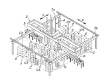
- FIG. 1 is a perspective view showing the entire transport container storage facility.
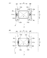
- FIG. 2A is a schematic plan view showing the container gripping lifting apparatus before gripping the container
- FIG. 2B is a schematic plan view showing the container gripping lifting apparatus after gripping the container.
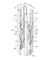
- FIG. 3 is a perspective view showing components of the container gripping lifting apparatus.
- FIG. 4 is a block diagram showing the relationship between the control device for the transport container storage facility and the display portable terminal.
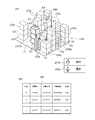
- FIG. 5 is a plan view showing a storage container on the storage area.
- FIG. 6A is a diagram showing a current storage state display image displayed on the touch screen of the display portable terminal
- FIG. 6B is displayed on the touch screen by a tap operation on a container image in the current storage state display image.
- FIG. 7A is a diagram showing a state in which the container image displayed on the touch screen of the display portable terminal is erased from the previous one
- FIG. 7B is a diagram showing a state in which the container image is further erased.
- 8A and 8B are diagrams showing a current storage state display image according to the embodiment of the second invention.
- this storage facility includes a rectangular flat storage area 1, a first traveling body 2, a second traveling body 3, a container gripping lifting device 4, a warehousing conveyor 5, and a warehousing facility. Consists of a conveyor 6.
- the direction parallel to one of the two right-angled sides of the rectangular plane is described as the X direction, and the direction parallel to the other side is described as the Y direction.
- Guide rails 7a and 7b are installed at a fixed height above the two sides in parallel with the Y direction, and both ends of the first traveling body 2 that are longer than the length of the storage area 1 in the X direction are provided on the guide rails 7a and 7b. By supporting the portion, the first traveling body 2 is supported so as to be movable parallel to the Y direction of the storage area 1 at a certain height above the storage area 1.
- the second traveling body 3 is supported on the first traveling body 2 so as to be movable in the X direction of the storage area 1, and the container grip lifting device 4 is supported on the second traveling body 3. Therefore, the container gripping lifting device 4 is configured to move the first traveling body 2 in the Y direction and the second traveling body 3 on the first traveling body 2 in the X direction. It can be positioned directly above the position.
- the container warehousing end portion of the warehousing conveyor 5 and the container warehousing start end portion of the warehousing conveyor 6 enter the storage area 1 so that the container gripping lifting device 4 can transfer the containers to these.
- Container C is a small plastic box-shaped container with a quadrangular plan shape that is open on the upper side, and is generally called a hand-held container. It can be stacked, and the outer peripheral surface can be a handle. With reinforcing horizontal overhanging ribs. In this storage facility, containers C of various plane sizes and heights are handled within the range that can be handled by the container gripping lifting device 4, and in principle, containers C having the same plane size are stepped within the allowable height range. Stacked.
- each container gripping unit 9 ⁇ / b> A, 9 ⁇ / b> B is long in the X direction between the opening that penetrates in the vertical direction of the plane quadrangle provided in the second traveling body 3 and the pair of Y-direction side frames that constitute the first traveling body 2. It moves up and down in the opening (see FIG.
- the pair of container gripping units 9A and 9B in the X direction move toward and away from each other in the X direction, and the long columnar members 11a and 11b of the container gripping units 9A and 9B have a constant position in the Y direction, With respect to these long columnar members 11a and 11b, a pair of holding long angle members 10a, 10b and 10c, 10d on both sides of the long columnar members 11a and 11b move close to and away from each other symmetrically in the Y direction.
- the pair of long angle members for gripping 10a, 10b and 10c, 10d in the Y direction are movable up and down supported so as to be movable up and down with respect to the long columnar members 11a and 11b located between them.
- the pair of X-direction long gripping angle members 10a, 10c and 10b, 10d are connected to the movable movable bodies 15a, 15b arranged in the middle of the pair of X-direction long angle members 10a, 10c, 10b, 10d.
- the four long gripping angle members 10a to 10d are connected to each other by two parallel links 16, and are configured to move toward and away from each other in the X and Y directions while maintaining a vertical posture.
- the four long-angle members for gripping 10a to 10d and the pair of long columnar members 11a and 11b in the X direction move up and down integrally, but do not move up and down individually.
- the container gripping lifting device 4 is positioned so that the container gripping lifting device 4 is positioned right above the container C to be loaded and unloaded.
- the second traveling body 3 supported at the upper limit height is traveled in the X direction relative to the first traveling body 2, and the first traveling body 2 is traveled in the Y direction.
- the container gripping unit 9A, 9B Before or during the movement of the first traveling body 2 and the second traveling body 3 for positioning the container gripping lifting device 4 at a position directly above the container C to be loaded / unloaded, the container gripping unit 9A, 9B itself moves in the X direction and the gripping long angle members 10a, 10b and 10c, 10d of each container gripping unit 9A, 9B move in the Y direction to perform four gripping long angle members 10a. ⁇ 10d and the container support means 12a and 12b can be moved to the elevation start position.
- the raising / lowering start positions of the four holding long angle members 10a to 10d are the positions of the four corners of a rectangular plane that is slightly larger than the plane size of the container C to be loaded and unloaded, and the positions of the container supporting means 12a and 12b are described above.
- the raising / lowering start position is the center position of both side surfaces parallel to the Y direction of a rectangular plane that is slightly larger than the plane size of the container C to be loaded / unloaded.
- the container gripping lifting device 4 is positioned directly above the container C to be loaded / unloaded, the gripping long angle members 10a to 10d of the container gripping units 9A and 9B positioned at the lifting start position, and the container
- the supporting means 12a, 12b (long columnar members 11a, 11b) are adjacent to the outside of the four corners of the container C to be loaded and unloaded, and the container supporting means 12a, 12b is loaded and unloaded.
- the target container C is lowered synchronously to a height adjacent to the reinforcing horizontal overhanging ribs on both side surfaces parallel to the Y direction.
- the container gripping units 9A and 9B are moved closer to each other in the X direction from the lift start position, and the gripping long angle members 10a, 10b and 10c, 10d of the container gripping units 9A, 9B are By moving closer to each other in the Y direction from the ascending / descending start position, the gripping long angle members 10a to 10d are fitted into the four corners of the container C to be loaded and unloaded, and the pair of container support means 12a and 12b in the X direction are inserted. Engage with reinforcing horizontal extending ribs on both sides parallel to the Y direction of the container C to be delivered.
- the gripping long angle members 10a to 10d of the container gripping units 9A and 9B, the container support means 12a, 12b are raised synchronously, so that the pair of container support means 12a and 12b in the X direction moves the container C to be stored and unloaded through the reinforcing horizontal extending rib of the container C. Can be lifted.
- the container support means 12a When the container C to be loaded / unloaded is a plurality of stacked containers C or a container C at an intermediate height among the stacked containers C, the container support means 12a, One or a plurality of containers C are stacked on one container C which 12b engages and lifts. If the container C to be loaded / unloaded with which the container support means 12a, 12b engage is lifted to a predetermined height, the container gripping lifting / lowering device 4 is moved to a position just above the place where the container C to be loaded / unloaded is lowered. As described above, the first traveling body 2 is traveled in the Y direction, and the second traveling body 3 is traveled in the X direction on the first traveling body 2.
- the container gripping lifting device 4 If the container gripping lifting device 4 is moved to a position just above the place where the container C to be stored / extracted is lowered, the container gripping units 9A, 9B are lowered and the container support means 12a, 12b is lifted The container C is lowered to a predetermined height at the lowering place.
- the container C to be loaded / unloaded (including the containers C stacked thereon)
- the long angle for gripping that is fitted to the four corners of the container C so as to move in the X direction with respect to the container support means 12a and 12b and to swing up and down around the support position by the container support means 12a and 12b.
- the materials 10a to 10d will block.
- the long holding angle members 10a to 10d of the container holding units 9A and 9B and the container supporting means 12a and 12b (long columnar members 11a and 11b) are connected.
- the container gripping units 9A and 9B are lifted and returned to the ascent limit, for example, and set in the storage area 1 if necessary. It is possible to return to the home position by the traveling operation of the first traveling body 2 and the second traveling body 3.
- the container C carried in by the warehousing conveyor 5 is transferred to any place in the storage area 1, that is, on the floor surface, by the transfer operation between the two points by lifting, transporting, and lowering the container C to be loaded and unloaded.
- the containers C stored in the storage area 1 (stacked containers) In the storage area 1, the re-entry work of the container to be unshipped located on the upper side of the stacked container C transferred on the conveyor 6, You can reposition the container storage location.
- the storage facility used as described above receives a warehousing instruction and a evacuation instruction, and automatically stores and moves out means for the storage facility, that is, the first traveling body 2 and the second traveling body.
- a portable display portable terminal (hereinafter simply referred to as a portable terminal) 18 is combined.
- the control device 17 includes an inventory database 17a of all articles stored in the container C and stored in the storage area 1, like a storage facility called a general automatic warehouse.
- the stock database 17a includes a container identification number for identifying each container C, the name and number of stored articles in each container C, a storage position on the storage area 1 of each container C (for example, a plan view of the container C).
- the portable terminal 18 includes a display having a multi-touch interface, that is, a touch screen 18c, which displays an inventory database 18a, an image creation / editing function 18b, and a current storage state display image created by the image creation / editing function 18b. ing.
- a display composed of a combination of a normal screen not equipped with a multi-touch interface and a trackpad for touch operation can be used.
- the portable terminal 18 is connected to the control device 17 via a communication means 19 (generally a wireless method is preferable, but a wired method may be used).
- the communication means 19 The inventory database 17a of the control device 17 connected via the mobile terminal 18 and the inventory database 18a of the portable terminal 18 are configured to automatically synchronize. However, the inventory database 18a of the portable terminal 18 is eliminated, and the control device 17 It is also possible to obtain necessary information from the inventory database 17a in real time. The following description is about the Example using the stock database 18a of the portable terminal 18.
- the portable terminal 18 When the portable terminal 18 is activated, as described above, the current storage information in the inventory database 18a of the portable terminal 18 is synchronized with the latest current storage information in the inventory database 17a of the control device 17, and the latest state Updated to Thus, when the current storage state display operation is performed on the portable terminal 18, the image creation / editing function 18b performs the four corners 1a to 1d of the storage area 1 based on the current storage information of the inventory database 18a.
- a current storage state display 3D image 20 shown in FIG. 6A corresponding to an overhead view when the entire storage area 1 is viewed from the reference overhead view position 20a above the outside of one corner 1a of the corner 1a is created, and the touch screen is displayed. 18c can be displayed.
- the stacked container group corresponding to the plurality of stacked container groups CX1 to CX5 shown in the plan view of the actual storage area 1 shown in FIG. 5 is the current storage state display 3D image 20 shown in FIG. It turns out that it is in a state where it cannot be visually recognized because it is hidden behind several stacked container groups CXx in front (viewpoint side).
- the touch screen 18c has a tap operation for hiding the displayed container image or stacked container group, and a specific container image or stacked container.
- Operation selection tap buttons 21a and 22a for selecting a tap operation for selecting a group image are displayed before the operation, and the tap operation for the hidden operation tap button 21a is displayed at an arbitrary position.
- the stacked container group CXx to be tapped can be erased (hidden).
- the tapping operation 21 is sequentially performed from the stacked container group CXx positioned at the foremost side of FIG. 6A to the stacked container group CXx at the back side, thereby the stacked container positioned at the foremost side of FIG. 6A.
- the group CXx can be sequentially erased from the rear stack container group CXx. In this manner, among the stacked container groups CX1x to CX5x that were not visible in FIG. 6A, the stacked container groups CX2x, CX3x, and CX5x can be made visible as shown in FIG. 7A. Further, as shown in FIG.
- the container image Cx or the stacked container group image CXx that is the target of the hidden tap operation 21 is erased, instead of erasing, only a transparent color or an outline line can be displayed (the rear container It is also possible to use a transparent image through which the image can be seen. Furthermore, it is also desirable to configure so that the container image Cx or the stacked container group image CXx switched to the erasable or transparent display can be returned to the original display state. As a specific method, when the hidden operation tap button 21a displayed on the touch screen 18c is tapped again, the container image Cx or the stacked container group image CXx that has been switched to erase or see-through display is displayed. It can be configured to return to the display state.
- supplementary work information such as exit prohibition settings and exit reservation settings can be displayed as a list on the touch screen 18c as necessary.
- the containers of all the stages shown in the stacked container group CXx are as described above.
- the list display 23 of information for each container is displayed and the side of one container image Cx is tapped, the information may be displayed as described above for only one container to be tapped. Is possible.
- the stacked containers that are set with respect to the unloading operation at that time such as “unloading containers” and “unloading reserved containers” on the inventory database 18 a.
- the exit prohibition container group CX6 and the exit reservation container group CX7 shown in FIG. 5 exist, as shown in FIG. 6A, the container image Cx or the stacked container displayed in the current storage state display 3D image 20 Of the group CXx, the container prohibition container group CX6x corresponding to the container prohibition container group CX6 and the container reservation container group CX7x corresponding to the container reservation container group CX7 are visually compared with other container images Cx or stacked container groups.
- the display state can be changed so that it can be easily identified from the image CXx.
- the display state can be changed by changing the display color, exaggerating the outline, displaying in color with respect to the monochrome display of other container images or stacked container groups, or vice versa.
- a transparent display of only the transparent color or outline of a container image or a group of stacked containers is displayed in substance (or vice versa).
- the above-described concealment tap operation 21 can be used in the following situations. That is, when the storage facility automatic entry / exit operation means, that is, when the first traveling body 2, the second traveling body 3, and the container gripping lifting device 4 can not be operated due to failure, The container contents that are urgently required must enter the storage area 1 and be discharged manually.
- the storage facility is a storage facility in which containers (including stacked containers) are placed flat on the floor surface of the storage area 1, so that the warehouse can be entered so that an operator can enter between the flat containers. As long as it is allowed to do so, it is possible to carry out the delivery work by hand.
- an outgoing product search input 24 is used to know the storage position of the container C that stores the outgoing product. Will do.
- the goods retrieval input 24 is basically performed with respect to the inventory database 17a of the host control device 17, but when the mobile terminal 18 has a search function by character input, the mobile terminal 18
- the goods retrieval input 24 can be performed on the inventory database 17a of the host control device 17 via the communication means 19, and the portable terminal 18 has the inventory database 18a as in the above embodiment.
- the retrieval result is input to the portable terminal 18 via the communication means 19.
- the above-mentioned outgoing goods retrieval input 24 identifies the emergency outgoing target container C in which the emergency outgoing goods manually stored are stored and its storage position.
- the portable terminal 18 displays the storage position of the emergency delivery target container C on the touch screen 18c based on the search result of the emergency delivery product. This display is displayed on the touch screen 18c.
- the emergency delivery target container image Cx corresponding to the emergency delivery target container C can be visually identified from among the container images Cx in the current storage state display 3D image 20.
- the display state is changed by the method. More specifically, it is assumed that the retrieved emergency delivery target container C is the uppermost container in one stacked container group CX4 placed at a certain position in the storage area 1 shown in FIG.
- the operator knows how the emergency delivery target container is displayed in the current storage state display 3D image 20, so that the emergency storage container 3D image 20 shown in FIG. Since it is known that the container image corresponding to the container to be delivered is not visible, from this point of time, using the concealing tap operation 21, the stacked container group sequentially from the front stacked container group CXx. The CXx is erased or converted into a transparent image, and the back side hidden container group group CXx is checked. Finally, when the process proceeds to the stage shown in FIG. In the uppermost row of the container group image CX4x, it is possible to find an emergency shipping object container image C1x having a different display state.
- the worker carrying the portable terminal 18 moves through the storage area 1 based on the display. It is possible to search for the intended emergency delivery container C while walking and visually comparing the display content of the portable terminal 18 with the nearby storage container.
- the storage area image 1x is displayed before the boundary line 25 by using the boundary line 25 that crosses the current storage state display 3D image 20 displayed on the touch screen 18c.
- a slider 26 is displayed on the touch screen 18c. The slider 26 taps and drags a tap portion 27 located at one end of the boundary line 25 along the guide scale to move from the front corner 1a of the storage area image 1x toward the innermost corner 1c.
- the boundary line 25 is moved, and the container image Cx or the stacked container group CXx that has entered the hidden area 1A before the boundary line 25 is converted into an erased or transmissive image.
- the boundary line 25 may not be displayed.
- a boundary line 25a that crosses the current storage state display 3D image 20 displayed on the touch screen 18c in the X direction and a boundary line 25b that crosses in the Y direction are used.
- the hidden area 1A in front of both the boundary lines 25a and 25b is divided into the display area 1B on the far side of the boundary lines 25a and 25b, and the boundary line 25a overlaps the right side between the corners 1a and 1b of the storage area image 1x. From the position overlapping the front side between the corners 1a and 1d of the storage area image 1x with the tap-and-drag slider 26a that moves in the X direction to the position overlapping the left side between the corners 1c and 1d and the corner 1b.
- a tap and drag type slider 26b that moves in the Y direction to a position overlapping the rear side is displayed on the touch screen 18c.
- the sliders 26a and 26b are formed by sliding the tap portions 27a and 27b located at one end of the boundary lines 25a and 25b along the guide scale by tapping and dragging, thereby hiding the hidden area on the front side of the boundary lines 25a and 25b.
- 1A can be expanded, and the container image Cx or the stacked container group image CXx entering the hidden area 1A is converted into an erased or transparent image.
- the boundary lines 25a and 25b need not be displayed.
- the current storage state display displayed on the touch screen 18c can be achieved by simply sliding the tap portion 27 or 27a, 27b of the slider 26 or 26a, 26b.
- the hidden area 1A of the 3D image 20 is gradually expanded from the near side to the far side, and the target container image hidden by the near container image Cx or the stacked container group group CXx, for example, the display in the stacked container group image CX4x It is possible to easily and efficiently find the emergency delivery object container image C1x in different states.
- the emergency delivery target container C is manually taken out and is directly stored in the storage area. Take it out of 1. In this case, the inventory completion of the emergency delivery target container C is performed on the portable terminal 18 or the control device 17, and the stock database 17a or 18a is updated.
- a plurality of containers C storing the intended emergency delivery items are searched, all of them are displayed so as to be identifiable as described above, and the operator selects the container that is most easily removed by hand. You may enable it to perform extraction work.
- all of the searches may be performed together to display a plurality of emergency delivery target container images.
- the container storage facility for transport using the portable terminal for display according to the present invention is a storage facility of a type in which containers (including stacked containers) that can be held in a flat storage area are placed horizontally, It can be used conveniently when the worker enters the warehouse and performs the warehouse work manually when the automatic delivery function becomes unavailable due to a failure.
Landscapes
- Engineering & Computer Science (AREA)
- Mechanical Engineering (AREA)
Abstract
本発明の搬送用容器保管設備は、入出庫装置を利用した自動入出庫作業に代えて、作業者が保管エリアに立ち入って手作業で出庫作業を行う際に、前記保管エリア内の全ての容器の現在保管位置を容器単位で視覚認識可能に図解表示する表示用携帯端末を利用することにより、当該手作業による出庫作業を、正確且つ能率良く行えるようにしたものであって、前記携帯端末の画面に表示されている容器画(Cx)又は段積み容器群画(CXx)から、タップ操作(21)により当該画面上で選択された特定容器画を、消去又は透明化するものである。
Description
本発明は、段積み可能な搬送用の容器の平面状の保管エリアと、この保管エリア内の選択された位置に対して容器の入庫・段積み・出庫を行う入出庫装置を備えた搬送用容器保管設備に関するものである。
上記のような搬送用容器保管設備は、例えば本出願人が先に出願致しました先願(特願2014-122242)に記載されるように、その実用化が待たれている。このような保管設備では、立体的なラックと、このラックに沿って走行する入出庫用走行クレーンとの組合せから成る、自動倉庫と称されるような保管設備と異なって、前記入出庫装置が故障したときなど、保管エリア内に保管されている容器を、当該保管エリア内に立ち入った作業者が手作業で出庫作業することが出来る。一方、種々のサイズの容器を効率良く保管するために、保管エリアを碁盤目状に区画して1区画に1つの容器を保管するのではなく、無駄な空間を残さないように、先に入庫された容器に対し必要空間を隔てて隣り合うように、容器を端から順番に詰めてゆくように入庫することになる。
上記のように使用される保管設備においては、前記入出庫装置を自動運転させるために必要な、保管エリア内の各保管容器に関する位置情報(例えば平面座標値X-Yと高さ座標値Z)が容器保管データベース上に記録されているが、前記入出庫装置が故障したときなど、保管エリア内に保管されている容器を、当該保管エリア内に立ち入った作業者が手作業で出庫作業しようとしたとき、前記容器保管データベースからの検索によって、手作業による出庫対象容器の位置情報を作業者が知ることが出来たとしても、そしてその位置情報を数値など文字情報で表示させることが出来たとしても、実際に保管エリア内に立ち入った作業者が、その位置情報に表わされる現実の出庫対象容器の位置を容易に特定することは難しい。従って現実には、前記入出庫装置が正常に稼働されるまで出庫作業を待つか、適当に目星をつけた位置の付近にある容器の中身を目視で確認しながら出庫対象容器を特定した上で、手作業による出庫作業を行うというような、非常に非能率的な作業に頼らなければならず、その影響は甚大である。
そこで、必要に応じて表示用携帯端末の画面上に、その時点での保管エリア上の容器保管状態を容器単位で視覚認識可能に図解表示させ、この携帯端末の現在保管状態表示画像上で、検索によって特定された手作業による出庫対象容器を表示させることが考えられたのであるが、当該携帯端末の広くない画面上には、手持ち可能な小型の容器又は段積み容器が不規則に且つ非常に数多く平置きされている保管エリアの全体が表示されているのであるから、出庫対象容器の位置によっては、その存在自体を探し出すのに非常に苦労することになる。又、検索された出庫対象容器を表示させる場合に限らず、非常時などにおいて、携帯端末の画面上に表示されている各容器画を、保管エリアの端から順番にタップするなどして、各容器画に対応する実際の容器の内容物を画面上に表示させるような使用方法をとる場合でも、目的の容器画が手前の容器画又は段積み容器画によって隠れてしまうなど、思うように容器画を選択することが出来ない。
本発明は、上記のような問題点を解消することのできる表示用携帯端末利用の搬送用容器保管設備を提案するものであって、本発明の第一発明に係る表示用携帯端末利用の搬送用容器保管設備は、後述する実施例との関係を理解し易くするために、当該実施例の説明において使用した参照符号を括弧付きで付して示すと、段積み可能な搬送用の容器(C)の平面状の保管エリア(1)と、この保管エリア(1)内の選択された位置に対して容器(C)の入庫・段積み・出庫を行う入出庫装置(2~6)を備えた搬送用容器の保管設備において、前記保管エリア(1)内の全ての容器(C)の現在保管位置を容器単位で視覚認識可能に図解表示する表示用携帯端末(18)を設け、この携帯端末(18)の画面に表示されている容器画に対するタップ操作(21)によって特定容器画を選択することにより、その選択された特定容器画が消去又は透明化される構成になっている。
又、本発明の第二発明に係る表示用携帯端末利用の搬送用容器保管設備は、段積み可能な搬送用の容器(C)の平面状の保管エリア(1)と、この保管エリア(1)内の選択された位置に対して容器(C)の入庫・段積み・出庫を行う入出庫装置(2~6)を備えた搬送用容器の保管設備において、前記保管エリア(1)内の全ての容器(C)の現在保管位置を容器単位で視覚認識可能に図解表示する表示用携帯端末(18)を設け、この携帯端末(18)の画面上には、前記保管エリア(1)を2分割する境界(境界線25又は25a,25b)が表示され、この境界(境界線25又は25a,25b)は、当該境界(境界線25又は25a,25b)に対するタッチインターフェースによって前記画面上で移動可能に構成され、前記境界(境界線25又は25a,25b)に対して視点側の保管エリア内の容器画(Cx)が、一時的に消去又は透明化される構成になっている。
尚、本発明の構成において「容器」と称しているものは、後述する実施例に示すプラスチック製で上側解放の小型コンテナの他、各種物品を搬送するために収容する、段積み可能な箱形、皿形など、形状や構造、素材、サイズなどが異なる各種の容器が含まれる。従って、前記入出庫装置は、この「容器」の形状や構造に適合した構成で実施される。又、本発明の構成における「表示用携帯端末」とは、一般的にタブレットやノートパソコンと称される小型のディスプレイ付きコンピューターを指すが、特に高度の演算能力を備えたものである必要はなく、場合によっては、この保管設備が備える制御装置に各種通信手段を介して接続される表示制御用のCPUを備えた、表示が主体の「表示用携帯端末」も含む。
上記本発明の構成によれば、前記表示用携帯端末に表示されている前記保管エリア内の現在保管状態表示画像中から特定の容器画を見つけ出すことが非常に容易に行える。例えば、入出庫装置が故障したときなどに手作業で出庫作業を行う出庫対象の容器を検索したとき、その検索結果の出庫対象容器を、現在保管状態表示画像中の対応する容器画の表示状態を変えて、作業者が視覚で識別可能にした場合、表示状態が変えられた出庫対象容器画が手前の容器画又は段積み容器画によって隠れている場合でも、第一発明では、現在保管状態表示画像中の選択した容器画に対するタップ操作により、第二発明では、容器画を消去又は透明化するためエリアを決めている境界を移動させるタッチ操作により、作業者に近い手前の容器画又は段積み容器画から順に消去又は透明化することにより、最終的に出庫対象容器画より手前の容器画又は段積み容器画の全てを消去又は透明化して、例えば出庫対象容器画を、作業者から見て最前列に現出させるなど、出庫対象容器の位置を簡単且つ正確に知ることが出来る画像状態に変化させることが出来る。
又、検索結果の容器の位置を知るためだけでなく、非常時などにおいて、携帯端末の画面上に表示されている各容器画を、保管エリアの端から順番にタップするなどして、各容器画に対応する実際の容器の内容物を画面上に表示させるような使用方法をとる場合でも、手前の容器画又は段積み容器画によって隠れてしまう容器画に対しても、当該手前の容器画又は段積み容器画を上記のような操作によって消去又は透明化することにより、簡単且つ確実に必要な操作を加えて、所期の目的を達成することが出来る。
しかも本発明の構成によれば、手前の容器画又は段積み容器画によって隠れている容器画を視覚により認識出来るようにするために、現在保管状態表示画像全体を水平方向のタップ&ドラッグ操作により水平方向に回転させて視点位置を変えたり、垂直方向のタップ&ドラッグ操作により垂直方向の俯瞰角度を変えたりして、死角になる部分を無くすような方法によるよりも、実施が容易で操作も簡単且つ能率的に行え、しかも目的の容器画又は段積み容器画そのものの全体を視認可能な状態とすることが出来、その効果は大きい。
尚、本発明において使用する表示用携帯端末のより一層の活用を図るために、
A.前記表示用携帯端末又は当該表示用携帯端末に接続された制御装置に対して出庫対象容器の検索を行ったとき、前記表示用携帯端末の画面上に表示されている現在保管状態表示画像中の各容器画の内、検索出力された出庫対象容器を示す容器画を、他の容器画に対し視覚による識別可能なように表示状態を変化させる。
B.前記表示用携帯端末の画面上に表示されている現在保管状態表示画像中の各容器画に対するタップ操作により容器画の一つを選択したとき、当該選択容器画に対応する容器の内容物に関する情報が、この表示用携帯端末の画面上に表示される。
C.前記表示用携帯端末の画面上に表示されている現在保管状態表示画像中の各容器画の内、出庫禁止容器・出庫予約容器など、その時点で出庫作業に関して設定されている特定容器に対応する容器画が、視覚により他の容器画と識別出来るように表示状態が変えられる。
D.前記表示用携帯端末の画面上には、保管エリア内の全ての保管容器を特定の条件で検索したときの特定容器一覧表が表示され、この特定容器一覧表から特定容器をタッチインターフェースにより選択操作したとき、その特定容器に対応する容器画が、視覚により他の容器画と識別出来るように表示状態が変えられる。
などの構成の1つ又は複数を採用することが出来る。これらの構成A~Dは、実用上は、例えば、段積み可能な搬送用の容器の平面状の保管エリアと、この保管エリア内の選択された位置に対して容器の入庫・段積み・出庫を行う入出庫装置を備え、前記保管エリア内の全ての容器の現在保管位置を容器単位で視覚認識可能に図解表示する携帯可能な表示用携帯端末を設けた、表示用携帯端末利用の搬送用容器保管設備と組み合わせて、効果的に利用することが出来るが、特に上記第一発明又は第二発明の構成と組み合わせることにより、より効果的に活用出来る。
A.前記表示用携帯端末又は当該表示用携帯端末に接続された制御装置に対して出庫対象容器の検索を行ったとき、前記表示用携帯端末の画面上に表示されている現在保管状態表示画像中の各容器画の内、検索出力された出庫対象容器を示す容器画を、他の容器画に対し視覚による識別可能なように表示状態を変化させる。
B.前記表示用携帯端末の画面上に表示されている現在保管状態表示画像中の各容器画に対するタップ操作により容器画の一つを選択したとき、当該選択容器画に対応する容器の内容物に関する情報が、この表示用携帯端末の画面上に表示される。
C.前記表示用携帯端末の画面上に表示されている現在保管状態表示画像中の各容器画の内、出庫禁止容器・出庫予約容器など、その時点で出庫作業に関して設定されている特定容器に対応する容器画が、視覚により他の容器画と識別出来るように表示状態が変えられる。
D.前記表示用携帯端末の画面上には、保管エリア内の全ての保管容器を特定の条件で検索したときの特定容器一覧表が表示され、この特定容器一覧表から特定容器をタッチインターフェースにより選択操作したとき、その特定容器に対応する容器画が、視覚により他の容器画と識別出来るように表示状態が変えられる。
などの構成の1つ又は複数を採用することが出来る。これらの構成A~Dは、実用上は、例えば、段積み可能な搬送用の容器の平面状の保管エリアと、この保管エリア内の選択された位置に対して容器の入庫・段積み・出庫を行う入出庫装置を備え、前記保管エリア内の全ての容器の現在保管位置を容器単位で視覚認識可能に図解表示する携帯可能な表示用携帯端末を設けた、表示用携帯端末利用の搬送用容器保管設備と組み合わせて、効果的に利用することが出来るが、特に上記第一発明又は第二発明の構成と組み合わせることにより、より効果的に活用出来る。
先ず、本発明の実施例に係る搬送用容器保管設備は、先に提示しました本出願人の先願において詳細構造が開示されたもので、その構成の概略を、図1~図3に基づいて説明すると、図1に示すように、この保管設備は、矩形平面状の保管エリア1、第一走行体2、第二走行体3、容器把持昇降装置4、入庫用コンベヤ5、及び出庫用コンベヤ6から構成されている。ここで、保管エリア1の平面視において、その矩形平面の直角二辺の一方と平行な方向をX方向、他方の辺と平行な方向をY方向として説明すると、保管エリア1のY方向の平行二側辺の上方一定高さに、Y方向と平行にガイドレール7a,7bが架設され、このガイドレール7a,7bに、保管エリア1のX方向長さより長尺の第一走行体2の両端部が支持されることにより、当該第一走行体2は、保管エリア1の上方一定高さを、保管エリア1のY方向に平行移動自在に支持されている。
第二走行体3は、第一走行体2上に、保管エリア1のX方向に移動自在に支持され、この第二走行体3に容器把持昇降装置4が支持されている。従って、この容器把持昇降装置4は、第一走行体2のY方向の移動と、この第一走行体2上での第二走行体3のX方向の移動とによって、保管エリア1の任意の位置の真上に位置させることが出来る。入庫用コンベヤ5の容器入庫終端部と、出庫用コンベヤ6の容器出庫始端部は、これらに対して容器把持昇降装置4が容器の移載を行えるように、保管エリア1内に入り込んでいる。容器Cは、平面形状が四角形で上側解放の、プラスチック製の小型箱形容器、一般に手持ち搬送用のコンテナと称されるもので、段積みも可能であり、外周面には、把手にもなり得る補強用水平張出しリブを備えている。この保管設備では、容器把持昇降装置4が取り扱える範囲内で各種の平面サイズと高さの容器Cが取り扱われ、原則的には、平面サイズが同一の容器Cは、許容高さ範囲内で段積みされる。
容器把持昇降装置4は、先に提示しました本出願人の先願において詳細に開示されているので、ここでは構成の概略を説明する。図2に記載のように、X方向に互いに接近離間移動自在に第二走行体3上に支持された可動台8a,8bと、これら両可動台8a,8bに支持された一対の容器把持ユニット9A,9Bを備えている。各容器把持ユニット9A,9Bは、第二走行体3に設けられた平面四角形の上下方向に貫通する開口部と、第一走行体2を構成するY方向一対の側枠間のX方向に長い開口部(図1参照)内を昇降するものであって、Y方向一対の把持用長尺アングル材10a,10b及び10c,10dと、把持用長尺アングル材10a,10b間の中央位置及び把持用長尺アングル材10c,10d間の中央位置に配設された長尺柱状部材11a,11bから構成され、X方向一対の長尺柱状部材11a,11bの下端部には容器支持手段12a,12bが支持されている。X方向一対の容器把持ユニット9A,9Bは、X方向に互いに接近離間移動するものであり、各容器把持ユニット9A,9Bの長尺柱状部材11a,11bは、Y方向位置は一定不変であり、これら長尺柱状部材11a,11bに対して、その両側のY方向一対の把持用長尺アングル材10a,10b及び10c,10dがY方向対称に接近離間移動するものである。
図3に示すように、Y方向一対の把持用長尺アングル材10a,10b及び10c,10dは、その中間に位置する長尺柱状部材11a,11bに対して昇降自在に支持された昇降可動体13a,13bに、上下二段の平行リンク14によって連結され、X方向一対の把持用長尺アングル材10a,10c及び10b,10dは、その中間に配置された昇降可動体15a,15bに、上下二段の平行リンク16によって連結され、4本の把持用長尺アングル材10a~10dが、垂直姿勢を保ってX方向及びY方向に互いに接近離間移動するように構成されている。尚、4本の把持用長尺アングル材10a~10dとX方向一対の長尺柱状部材11a,11bは、一体に昇降移動するが、個別には昇降移動しない構造となっている。
上記構成の容器把持昇降装置4による容器Cの昇降搬送時の作用を説明すると、入出庫対象の容器Cの真上位置に容器把持昇降装置4を位置させるように、当該容器把持昇降装置4が上昇限高さで支持されている第二走行体3を第一走行体2に対してX方向に走行移動させると共に、第一走行体2をY方向に走行移動させる。尚、この入出庫対象の容器Cの真上位置に容器把持昇降装置4を位置させるための第一走行体2及び第二走行体3の移動開始前又はその移動中に、容器把持ユニット9A,9B自体のX方向の接近移動と、各容器把持ユニット9A,9Bの把持用長尺アングル材10a,10b及び10c,10dのY方向接近移動とを実行し、4つの把持用長尺アングル材10a~10dと容器支持手段12a,12bを、昇降開始位置に移動させておくことが出来る。又、4つの把持用長尺アングル材10a~10dの前記昇降開始位置は、入出庫対象の容器Cの平面サイズより一回り大きい矩形平面の四隅の位置であり、容器支持手段12a,12bの前記昇降開始位置は、入出庫対象の容器Cの平面サイズより一回り大きい矩形平面のY方向と平行な両側面の中央位置である。
入出庫対象の容器Cの真上位置に容器把持昇降装置4を位置させたならば、前記昇降開始位置に位置させた容器把持ユニット9A,9Bの把持用長尺アングル材10a~10dと、容器支持手段12a,12b(長尺柱状部材11a,11b)を、把持用長尺アングル材10a~10dが入出庫対象の容器Cの四隅の外側に隣接すると共に、容器支持手段12a,12bが入出庫対象の容器CのY方向と平行な両側面の補強用水平張出しリブに隣接する高さまで、同期させて下降させる。この後、容器把持ユニット9A,9Bを、前記昇降開始位置より更にX方向に互いに接近移動させると共に、各容器把持ユニット9A,9Bの把持用長尺アングル材10a,10b及び10c,10dを、前記昇降開始位置より更にY方向に互いに接近移動させることにより、把持用長尺アングル材10a~10dを入出庫対象の容器Cの四隅に嵌合させ且つX方向一対の容器支持手段12a,12bを入出庫対象の容器CのY方向と平行な両側面の補強用水平張出しリブに係合させる。
上記のようにして、入出庫対象の容器Cを容器把持ユニット9A,9Bが把持し終わったならば、容器把持ユニット9A,9Bの把持用長尺アングル材10a~10dと、容器支持手段12a,12b(長尺柱状部材11a,11b)を、同期させて上昇させることにより、X方向一対の容器支持手段12a,12bが入出庫対象の容器Cを、当該容器Cの補強用水平張出しリブを介して吊り上げることが出来る。この入出庫対象の容器Cが、段積みされた複数の容器Cである場合や、段積みされた複数の容器Cの中の中間高さにある容器Cであるときは、容器支持手段12a,12bが係合して吊り上げる1つの容器Cの上に1つ又は複数の容器Cが段積み状態にある。容器支持手段12a,12bが係合する入出庫対象の容器Cが所定高さまで吊り上げられたならば、次に、入出庫対象の容器Cの降ろし場所の真上位置まで容器把持昇降装置4を移動させるように、第一走行体2をY方向に走行させると共に、この第一走行体2上で第二走行体3をX方向に走行させる。
入出庫対象の容器Cの降ろし場所の真上位置まで容器把持昇降装置4を移動させたならば、容器把持ユニット9A,9Bを下降させて、容器支持手段12a,12bが吊り上げている入出庫対象の容器Cを、降ろし場所における所定高さまで下降させる。上記の入出庫対象の容器Cの吊上げ開始から降ろし場所での下降終了までの一連の容器搬送行程においては、入出庫対象の容器C(その上に段積みされている容器Cも含む)が、容器支持手段12a,12bに対してX方向に移動したり、容器支持手段12a,12bによる支持位置を支点に上下に揺れ動くのを、当該容器Cの四隅に嵌合している把持用長尺アングル材10a~10dが阻止することになる。入出庫対象の容器Cの降ろし場所での下降終了後は、容器把持ユニット9A,9Bの把持用長尺アングル材10a~10dと、容器支持手段12a,12b(長尺柱状部材11a,11b)を、前記昇降開始位置まで水平移動させて、入出庫対象の容器Cから外側へ離間させた後に、容器把持ユニット9A,9Bを例えば上昇限まで上昇復帰させ、必要ならば、保管エリア1内に設定されたホームポジションまで、第一走行体2と第二走行体3の走行動作により復帰させておくことが出来る。
以上の入出庫対象の容器Cの吊上げ、搬送、降ろしによる2地点間の移載動作により、入庫用コンベヤ5により搬入された容器Cを、保管エリア1内に任意の場所、即ち、床面上の空き領域や、先に保管されている容器C(段積み容器を含む)上へ移載する、入庫・段積み作業の他、保管エリア1内に保管されている容器C(段積み容器を含む)を出庫用コンベヤ6上へ移載する出庫作業、出庫用コンベヤ6上に移載された段積み容器Cの内、上側に位置する非出庫対象容器の再入庫作業、保管エリア1内の容器の保管場所の位置替え作業などが行える。
以上のように使用される保管設備には、図4に示すように、入庫指令や出庫指令を受けて、当該保管設備の自動入出庫作業用手段、即ち、第一走行体2、第二走行体3、及び容器把持昇降装置4、を自動制御するための制御装置17とは別に、携帯可能な表示用携帯端末(以下、携帯端末と略称する)18が組み合わされている。制御装置17は、一般的な自動倉庫と称されるような保管設備と同じように、容器Cに収納されて保管エリア1内で保管されている全ての物品の在庫データベース17aを備えている。この在庫データベース17aは、各容器Cを特定する容器識別番号、各容器C内の収納物品名と個数、各容器Cの保管エリア1上の平面視における保管位置(例えば、当該容器Cの平面視における中心位置の保管エリア1上のX-Y座標値)、段積みされている各容器Cについては何段目かを示す段数、入庫日時などの基本情報の他、必要に応じて、出庫禁止設定、出庫予約設定などの作業補足情報が設定され、容器Cの入出庫作業ごとに、情報の更新(追加・削除・編集)が自動的に行われる。
携帯端末18は、在庫データベース18a、画像作成・編集機能18b、及び画像作成・編集機能18bが作成した現在保管状態表示画像を表示する、マルチタッチインターフェースを備えたディスプレイ、即ち、タッチスクリーン18cを備えている。勿論、タッチスクリーン18cに代えて、マルチタッチインターフェースを備えていない通常型スクリーンとタッチ操作用のトラックパッドとの組み合わせからなるディスプレイを利用することも出来る。この携帯端末18は、通信手段(一般的には無線方式が望ましいが、有線方式でも良い)19を介して前記制御装置17と接続されるもので、この携帯端末18を起動すると、通信手段19を介して接続される制御装置17の在庫データベース17aと、この携帯端末18の在庫データベース18aとが自動同期するように構成しているが、携帯端末18の在庫データベース18aを無くして、制御装置17の在庫データベース17aから必要な情報をリアルタイムに得るように構成することも出来る。以下の説明は、携帯端末18の在庫データベース18aを利用する実施例についての説明となっている。
今、保管エリア1内の現在保管状態を平面図で表示したとき、図5に示すように、各種サイズの平面四角形の段積み容器群CX(中には、段積みされていない単体の容器Cも含まれる)が、不規則に、しかし各容器Cの直角2側辺がX方向とY方向とに平行になる向きで平置きされた状態であったとする。携帯端末18が起動されると、先に説明したように、当該携帯端末18の在庫データベース18aの現在保管情報が、制御装置17の在庫データベース17aの最新の現在保管情報と同期して、最新状態に更新される。而して、この携帯端末18に対して現在保管状態表示操作を実行したとき、画像作成・編集機能18bは、当該在庫データベース18aの現在保管情報に基づいて、保管エリア1の四コーナー1a~1dの内の1つのコーナー1aの外側上方の基準俯瞰視点位置20aから保管エリア1の全体を俯瞰したときの俯瞰図に相当する、図6Aに示す現在保管状態表示3D画像20を作成し、タッチスクリーン18c上に表示することが出来る。しかしながら、図5に示す実際の保管エリア1の平面図に示される複数の段積み容器群CX1~CX5に対応する段積み容器群画が、この図6Aに示す現在保管状態表示3D画像20では、手前(視点側)にある幾つかの段積み容器群画CXxの陰に隠れて視認出来ない状態にあることがわかる。
勿論、図6Aに示す現在保管状態表示3D画像20では、実際に手前にある段積み容器群図CXxの陰に隠れて視認出来ない容器画又は段積み容器群画があるか否かは不明である。このような状況に対処するため、図6Aに示すように、タッチスクリーン18cには、表示されている容器画又は段積み容器群画を隠すためのタップ操作と、特定の容器画又は段積み容器群画を選択するためのタップ操作とを、操作の前に選択するための操作選択用タップボタン21a,22aが表示されており、隠し操作用タップボタン21aをタップした後に、任意の位置にある段積み容器群画CXxの最上端面をタップ操作21することにより、当該タップ操作対象の段積み容器群画CXxを消去する(隠す)ことが出来るように構成している。このタップ操作21を、図6Aの最も手前に位置する段積み容器群画CXxから奥側の段積み容器群画CXxへ順番に行ってゆくことにより、図6Aの最も手前に位置する段積み容器群画CXxから奥側の段積み容器群画CXxへ順番に消去することが出来る。このようにして、図6Aでは見えなかった段積み容器群画CX1x~CX5xの内、段積み容器群CX2x,CX3x,CX5xを、図7Aに示すように可視状態とすることが出来る。更に、図7Aに示すように、タップ操作21を加えて、手前の段積み容器群画CXxを順次消してゆくことにより、図7Bに示すように、見えなかった最後の2つの段積み容器群画CX1x,CX4xを可視状態にすることが出来る。
尚、隠しタップ操作21の対象となった容器画Cx又は段積み容器群画CXxを消去するように説明したが、消去に代えて、透明色又は輪郭線のみの透視可表示(後ろ側の容器画が透けて見える透過性画像)とすることも可能である。更に、消去又は透視可表示に切り換えた容器画Cx又は段積み容器群画CXxを元の表示状態に戻すことが出来るように構成することも望ましいことである。具体的な方法としては、タッチスクリーン18c上に表示されている隠し操作用タップボタン21aを再度タップ操作したときに、消去又は透視可表示に切り換えた容器画Cx又は段積み容器群画CXxが元の表示状態に戻るように構成することが出来る。
図6Aに示す現在保管状態表示3D画像20や、手前の容器画又は段積み容器群画を隠すためのタップ操作21を行った後の、図7に示す現在保管状態表示3D画像20において、表示されている特定の容器画に対応する容器の内容物などの情報を知りたいときは、前記選択用タップボタン21a,22aの内、選択操作用タップボタン22aをタップした後に、情報を知りたい特定の容器画に対しタップ操作22(図6A参照)を行う。この結果、そのタップ操作によって選択された容器画に対応する特定容器が在庫データベース18aから検索され、この特定容器の容器識別番号、収納物品名と個数、段積みされている容器であるときは何段目かを示す段数、入庫日時などの基本情報の他、必要に応じて、出庫禁止設定、出庫予約設定などの作業補足情報が、そのタッチスクリーン18c上に一覧表示させることが出来る。この場合、図6Bに示すように、任意の段積み容器群画CXxの最上端面をタップ操作22したときは、当該段積み容器群画CXxに示される全ての段の容器について、上記のように容器別の情報の一覧表示23をさせ、1つの容器画Cxの側面をタップ操作したときは、当該タップ操作対象の1つの容器についてのみ、上記のように情報を表示させるように構成することも可能である。
尚、図6A及び図7に示す現在保管状態表示3D画像20においては、在庫データベース18a上で「出庫禁止容器」や「出庫予約容器」など、その時点で出庫作業に関して設定されている段積み容器、例えば図5に示す出庫禁止容器群CX6や出庫予約容器群CX7が存在するときは、図6Aに示すように、現在保管状態表示3D画像20中に表示されている容器画Cx又は段積み容器群画CXxの内、出庫禁止容器群CX6に対応する出庫禁止容器群画CX6xや、出庫予約容器群CX7に対応する出庫予約容器群画CX7xが、視覚により他の容器画Cx又は段積み容器群画CXxと容易に識別出来るように表示状態が変えられているようにすることが出来る。この場合の表示状態の変更は、表示色を変える、輪郭を誇張表示する、他の容器画又は段積み容器群画のモノクロ表示に対してカラー表示にする(又はその逆にする)、他の容器画又は段積み容器群画の透明色又は輪郭線のみの透視可表示(後ろ側の容器画が透けて見える透過性画像)に対して実体表示にする(又はその逆にする)、などが考えられるが、出庫禁止容器に対応する容器画又は段積み容器群画を表示しないことも1つの方法である。
上記の隠し用タップ操作21は、次のような事態に際しても活用出来る。即ち、この保管設備の自動入出庫作業用手段、即ち、第一走行体2、第二走行体3、及び容器把持昇降装置4が故障などによって稼働させることが出来ない状況になったときは、緊急に必要となった容器内容物は、保管エリア1内に作業者が立ち入って手作業で出庫作業しなければならない。換言すれば、保管エリア1の床面上に容器(段積み容器を含む)が平置きされる保管設備であるから、平置きされた容器間に作業者が立ち入ることが出来る状態に入庫を実行させておきさえすれば、手作業による出庫作業が可能である。このような非常事態によって、手作業による出庫作業を実行しなければならなくなった場合、図4に示すように、その出庫品を収納する容器Cの保管位置を知るために、出庫品検索入力24を行うことになる。この出庫品検索入力24は、基本的には上位の制御装置17の在庫データベース17aに対して行うことになるが、携帯端末18に、文字入力による検索機能があるときは、この携帯端末18から、通信手段19を経由して上位の制御装置17の在庫データベース17aに対して、出庫品検索入力24を行うことも可能であり、上記実施例のように携帯端末18に在庫データベース18aがあるときは、当該在庫データベース18aに対して、出庫品検索入力24を行うことも可能である。制御装置17側で出庫品検索入力24を行ったときは、その検索結果が通信手段19を経由して携帯端末18に入力されることになる。
何れにしても、上記の出庫品検索入力24によって、手作業による非常時出庫品が収納されている非常時出庫対象容器Cとその保管位置が特定される。携帯端末18は、この非常時出庫品の検索結果に基づいて、非常時出庫対象容器Cの保管位置をタッチスクリーン18c上に表示することになるが、この表示は、タッチスクリーン18c上に表示されていた現在保管状態表示3D画像20中の容器画Cxの中から、非常時出庫対象容器Cに対応する非常時出庫対象容器画Cxを、視覚による識別可能なように段落0028において説明したような方法で表示状態を変化させることである。具体的に説明すると、検索された非常時出庫対象容器Cが、図5に示す保管エリア1内の或る位置に置かれている1つの段積み容器群CX4の中の最上段容器であったとすると、図6Aに示すように、保管エリア全域の現在保管状態表示3D画像20中では、段積み容器群CX4に対応する段積み容器群画は、手前の段積み容器群画CXxによって直接見ることが出来ない状況である。
作業者は、非常時出庫対象容器が現在保管状態表示3D画像20中でどのように表示されるかを知っておくことにより、図6Aに示す現在保管状態表示3D画像20中には、非常時出庫対象容器に対応する容器画が見えていないことを知ることになるので、この時点から、前記隠し用タップ操作21を使用して、手前の段積み容器群画CXxから順次段積み容器群画CXxを消去又は透過性画像に変換し、後ろ側の隠れていた段積み容器群画CXxをチェックしてゆくことになり、最終的には、図7Bに示す段階まで進んだ時点で、段積み容器群画CX4xの最上段に、表示状態が異なる非常時出庫対象容器画C1xを見つけ出すことが出来る。このようにして、非常時出庫対象容器Cの保管位置をタッチスクリーン18c上で確認することが出来たならば、この携帯端末18を携行する作業者は、その表示に基づいて保管エリア1内を歩行し、携帯端末18の表示内容と付近の保管容器とを視覚的に比較しながら、目的の非常時出庫対象容器Cを探索することが出来る。
図8Aに示す第二発明の実施例では、タッチスクリーン18c上に表示させた現在保管状態表示3D画像20を横断する境界線25を使用して、保管エリア画1xを、当該境界線25より手前の隠し領域1Aと当該境界線25より奥側の表示領域1Bとに分け、この境界線25を保管エリア画1xの手前のコーナー1aから最奥のコーナー1cに向かって移動させるタップ&ドラッグ方式のスライダー26をタッチスクリーン18c上に表示させている。このスライダー26は、前記境界線25の一端に位置するタップ部27をガイドスケールに沿ってタップ&ドラッグによりスライドさせることによって、保管エリア画1xの手前のコーナー1aから最奥のコーナー1cに向かって境界線25を移動させるものであって、この境界線25より手前の隠し領域1Aに入った容器画Cx又は段積み容器群画CXxを、消去又は透過性画像に変換するものである。境界線25は、表示しなくとも良い。
又、図8Bに示す実施例では、タッチスクリーン18c上に表示させた現在保管状態表示3D画像20をX方向に横断する境界線25aと、Y方向に横断する境界線25bとを使用して、両境界線25a,25bより手前の隠し領域1Aと当該境界線25a,25bより奥側の表示領域1Bとに分け、境界線25aを、保管エリア画1xのコーナー1a,1b間の右辺に重なる位置からコーナー1c,1d間の左辺に重なる位置までX方向に移動させるタップ&ドラッグ方式のスライダー26aと、境界線25bを、保管エリア画1xのコーナー1a,1d間の前側辺に重なる位置からコーナー1b,1c間の後側辺に重なる位置までY方向に移動させるタップ&ドラッグ方式のスライダー26bを、タッチスクリーン18c上に表示させている。このスライダー26a,26bは、前記境界線25a,25bの一端に位置するタップ部27a,27bをガイドスケールに沿ってタップ&ドラッグによりスライドさせることによって、両境界線25a,25bより手前側の隠し領域1Aを拡張させてゆくことが出来、この隠し領域1Aに入った容器画Cx又は段積み容器群画CXxを、消去又は透過性画像に変換するものである。境界線25a,25bは、表示しなくとも良い。
上記の図8に示した第二発明の実施例によれば、スライダー26又は26a,26bのタップ部27又は27a,27bをスライドさせるだけで、タッチスクリーン18c上に表示されている現在保管状態表示3D画像20の隠し領域1Aを手前から奥側へ漸次広げてゆき、手前の容器画Cx又は段積み容器群画CXxによって隠れていた目的の容器画、例えば、段積み容器群画CX4x中の表示状態が異なる非常時出庫対象容器画C1xを容易且つ能率良く見つけ出すことが出来る。
以上のようにして作業者が、携帯端末18の表示から目的の非常時出庫対象容器Cを特定することが出来たならば、当該非常時出庫対象容器Cを手作業で取り出して、そのまま保管エリア1の外へ持ち出せば良い。この場合、携帯端末18又は制御装置17に対して非常時出庫対象容器Cの出庫完了操作を行って、在庫データベース17a又は18aを更新しておくことになる。又、目的の非常時出庫対象物品を収納した容器Cが複数検索されたならば、その全てを上記のように識別可能に表示させて、作業者が手作業で最も取り出し易い容器を選択して取出し作業を行えるようにしても良い。又、目的の非常時出庫対象物品が複数ある場合は、その全ての検索をまとめて行い、複数の非常時出庫対象容器画を表示させるようにしても良い。更に、このように表示させた非常時出庫対象容器画をタップ操作することにより、先に説明したように、非常時出庫対象容器画に対応する非常時出庫対象容器Cの内容物についての情報をタッチスクリーン18c上に表示させて、検索結果に誤りがないか確認出来るようにしても良い。勿論、非常時出庫品の検索入力時に個数が入力された時は、その個数の全てを出庫するのに足りるだけの数の容器が検索され、表示される。
本発明に係る表示用携帯端末利用の搬送用容器保管設備は、平面状の保管エリア内に手持ち可能なサイズの容器(段積み容器を含む)が平置きされるタイプの保管設備であって、故障などにより自動出庫機能が使えなくなったときに、作業者が立ち入って手作業で出庫作業を行う場合などに便利に活用出来る。
1 保管エリア
1x 保管エリア画
2 第一走行体
3 第二走行体
4 容器把持昇降装置
5 入庫用コンベヤ
6 出庫用コンベヤ
8a,8b 可動台
9A,9B 容器把持ユニット
10a~10d 把持用長尺アングル材
11a,11b 長尺柱状部材
12a,12b 容器支持手段
17 制御装置
17a 在庫データベース
18 携帯端末
18a 在庫データベース
18b 画像作成・編集機能
18c タッチスクリーン
19 通信手段
20 現在保管状態を表示する3D画像
20a,20b 俯瞰視点位置
21 隠し用タップ操作
22 選択用タップ操作
23 容器別情報一覧表示
24 出庫品検索入力
25,25a,25b 境界線
26,26a,26b タップ&ドラッグ方式のスライダー
27,27a,27b タップ部
C 容器
Cx 容器画
C1x 非常時出庫対象容器画
CX,CX1~CX5 段積み容器群
CXx,CX1x~CX5x 段積み容器群画
CX6x 出庫禁止容器群画
CX7x 出庫予約容器群画
1x 保管エリア画
2 第一走行体
3 第二走行体
4 容器把持昇降装置
5 入庫用コンベヤ
6 出庫用コンベヤ
8a,8b 可動台
9A,9B 容器把持ユニット
10a~10d 把持用長尺アングル材
11a,11b 長尺柱状部材
12a,12b 容器支持手段
17 制御装置
17a 在庫データベース
18 携帯端末
18a 在庫データベース
18b 画像作成・編集機能
18c タッチスクリーン
19 通信手段
20 現在保管状態を表示する3D画像
20a,20b 俯瞰視点位置
21 隠し用タップ操作
22 選択用タップ操作
23 容器別情報一覧表示
24 出庫品検索入力
25,25a,25b 境界線
26,26a,26b タップ&ドラッグ方式のスライダー
27,27a,27b タップ部
C 容器
Cx 容器画
C1x 非常時出庫対象容器画
CX,CX1~CX5 段積み容器群
CXx,CX1x~CX5x 段積み容器群画
CX6x 出庫禁止容器群画
CX7x 出庫予約容器群画
Claims (6)
- 段積み可能な搬送用の容器の平面状の保管エリアと、この保管エリア内の選択された位置に対して容器の入庫・段積み・出庫を行う入出庫装置を備えた搬送用容器の保管設備において、前記保管エリア内の全ての容器の現在保管位置を容器単位で視覚認識可能に図解表示する表示用携帯端末を設け、この携帯端末の画面に表示されている容器画に対するタップ操作によって特定容器画を選択することにより、その選択された特定容器画が消去又は透明化されるように構成されている、表示用携帯端末利用の搬送用容器保管設備。
- 段積み可能な搬送用の容器の平面状の保管エリアと、この保管エリア内の選択された位置に対して容器の入庫・段積み・出庫を行う入出庫装置を備えた搬送用容器の保管設備において、前記保管エリア内の全ての容器の現在保管位置を容器単位で視覚認識可能に図解表示する表示用携帯端末を設け、この携帯端末の画面上には、前記保管エリアを2分割する境界が表示され、この境界は、当該境界に対するタッチインターフェースによって前記画面上で移動可能に構成され、前記境界に対して視点側の保管エリア内の容器画が、一時的に消去又は透明化されるように構成されている、表示用携帯端末利用の搬送用容器保管設備。
- 前記表示用携帯端末又は当該表示用携帯端末に接続された制御装置に対して出庫対象容器の検索を行ったとき、前記表示用携帯端末の画面上に表示されている現在保管状態表示画像中の各容器画の内、検索出力された出庫対象容器を示す容器画を、他の容器画と視覚による識別可能なように表示状態を変化させるように構成された、請求項1又は2に記載の表示用携帯端末利用の搬送用容器保管設備。
- 前記表示用携帯端末の画面上に表示されている現在保管状態表示画像中の容器画に対するタップ操作により容器画の一つを選択したとき、当該選択容器画に対応する容器の内容物に関する情報が、この表示用携帯端末の画面上に表示されるように構成された、請求項1又は2に記載の表示用携帯端末利用の搬送用容器保管設備。
- 前記表示用携帯端末の画面上に表示されている現在保管状態表示画像中の各容器画の内、出庫禁止容器・出庫予約容器など、その時点で出庫作業に関して設定されている特定容器に対応する容器画が、視覚により他の容器画と識別出来るように表示状態が変えられている、請求項1又は2に記載の表示用携帯端末利用の搬送用容器保管設備。
- 前記表示用携帯端末の画面上には、保管エリア内の全ての保管容器を特定の条件で検索したときの特定容器一覧表が表示され、この特定容器一覧表から特定容器をタッチインターフェースにより選択操作したとき、その特定容器に対応する容器画が、視覚により他の容器画と識別出来るように表示状態が変えられる、請求項1又は2に記載の表示用携帯端末利用の搬送用容器保管設備。
Applications Claiming Priority (2)
| Application Number | Priority Date | Filing Date | Title |
|---|---|---|---|
| JP2015-016489 | 2015-01-30 | ||
| JP2015016489A JP2016141497A (ja) | 2015-01-30 | 2015-01-30 | 表示用携帯端末利用の搬送用容器保管設備 |
Publications (1)
| Publication Number | Publication Date |
|---|---|
| WO2016121487A1 true WO2016121487A1 (ja) | 2016-08-04 |
Family
ID=56543107
Family Applications (1)
| Application Number | Title | Priority Date | Filing Date |
|---|---|---|---|
| PCT/JP2016/050694 Ceased WO2016121487A1 (ja) | 2015-01-30 | 2016-01-12 | 表示用携帯端末利用の搬送用容器保管設備 |
Country Status (3)
| Country | Link |
|---|---|
| JP (1) | JP2016141497A (ja) |
| TW (1) | TW201628947A (ja) |
| WO (1) | WO2016121487A1 (ja) |
Families Citing this family (2)
| Publication number | Priority date | Publication date | Assignee | Title |
|---|---|---|---|---|
| JP7134073B2 (ja) * | 2018-11-14 | 2022-09-09 | 株式会社ダイフク | 物品積載設備 |
| CN116750387B (zh) * | 2023-07-06 | 2025-11-25 | 深圳市海柔创新科技有限公司 | 针对叠放箱的仓储管理方法及相关装置 |
Citations (7)
| Publication number | Priority date | Publication date | Assignee | Title |
|---|---|---|---|---|
| JPH0873010A (ja) * | 1994-09-02 | 1996-03-19 | Murata Mach Ltd | 搬送システムの移動先指示装置 |
| JP2000318810A (ja) * | 1999-05-06 | 2000-11-21 | Nec Soft Ltd | 倉庫内三次元ロケーション管理装置および方法 |
| JP2006282341A (ja) * | 2005-03-31 | 2006-10-19 | Chugoku Electric Power Co Inc:The | 位置情報管理装置、位置情報管理方法、及びプログラム |
| JP2007238236A (ja) * | 2006-03-07 | 2007-09-20 | Toppan Forms Co Ltd | 物品管理システム |
| WO2011155118A1 (ja) * | 2010-06-07 | 2011-12-15 | パナソニック株式会社 | オブジェクト選択装置、オブジェクト選択プログラム、及びオブジェクト選択方法 |
| JP2013037476A (ja) * | 2011-08-05 | 2013-02-21 | Nikon Corp | 観察装置、観察方法、及び撮像装置 |
| JP2014177337A (ja) * | 2013-03-15 | 2014-09-25 | Daifuku Co Ltd | 物品搬送用箱の搬送装置 |
-
2015
- 2015-01-30 JP JP2015016489A patent/JP2016141497A/ja active Pending
- 2015-10-07 TW TW104132968A patent/TW201628947A/zh unknown
-
2016
- 2016-01-12 WO PCT/JP2016/050694 patent/WO2016121487A1/ja not_active Ceased
Patent Citations (7)
| Publication number | Priority date | Publication date | Assignee | Title |
|---|---|---|---|---|
| JPH0873010A (ja) * | 1994-09-02 | 1996-03-19 | Murata Mach Ltd | 搬送システムの移動先指示装置 |
| JP2000318810A (ja) * | 1999-05-06 | 2000-11-21 | Nec Soft Ltd | 倉庫内三次元ロケーション管理装置および方法 |
| JP2006282341A (ja) * | 2005-03-31 | 2006-10-19 | Chugoku Electric Power Co Inc:The | 位置情報管理装置、位置情報管理方法、及びプログラム |
| JP2007238236A (ja) * | 2006-03-07 | 2007-09-20 | Toppan Forms Co Ltd | 物品管理システム |
| WO2011155118A1 (ja) * | 2010-06-07 | 2011-12-15 | パナソニック株式会社 | オブジェクト選択装置、オブジェクト選択プログラム、及びオブジェクト選択方法 |
| JP2013037476A (ja) * | 2011-08-05 | 2013-02-21 | Nikon Corp | 観察装置、観察方法、及び撮像装置 |
| JP2014177337A (ja) * | 2013-03-15 | 2014-09-25 | Daifuku Co Ltd | 物品搬送用箱の搬送装置 |
Also Published As
| Publication number | Publication date |
|---|---|
| JP2016141497A (ja) | 2016-08-08 |
| TW201628947A (zh) | 2016-08-16 |
Similar Documents
| Publication | Publication Date | Title |
|---|---|---|
| US20210090001A1 (en) | Warehouse management, a robot and an adaptor | |
| EP4125016B1 (en) | System and method for consolidating items for fulfilment of order in warehouse | |
| JP5093177B2 (ja) | 自動倉庫 | |
| JP7143145B2 (ja) | 自動倉庫システム | |
| JP4582421B2 (ja) | 自動倉庫 | |
| EP3257791B1 (en) | Planar storage facility | |
| WO2016121487A1 (ja) | 表示用携帯端末利用の搬送用容器保管設備 | |
| CN108602620A (zh) | 出入库作业辅助系统、出入库作业辅助方法以及程序 | |
| JP6559746B2 (ja) | 仕分けシステム | |
| WO2016121486A1 (ja) | 表示用携帯端末利用の搬送用容器保管設備 | |
| JP3760756B2 (ja) | 棚設備 | |
| JP2013252905A (ja) | 物品の保管方法および物品保管設備 | |
| JP3832997B2 (ja) | 物品保管管理システム | |
| JP6699510B2 (ja) | 参拝設備 | |
| JP2003176025A (ja) | 単一商品の自動積み付けロボットシステムにおける荷姿作成方法及びその装置 | |
| JP6693299B2 (ja) | ピッキングシステム及びピッキングシステムの制御方法 | |
| JP2018043804A (ja) | 平置き保管設備 | |
| CN116198887A (zh) | 自动仓库系统及自动仓库的控制方法 | |
| WO2022124141A1 (ja) | 平面保管設備(plane storage facility) | |
| JP3824136B2 (ja) | 自動倉庫システムの棚卸し制御装置 | |
| JP2005272147A (ja) | 物品保管管理システム | |
| JP4446910B2 (ja) | 図書保管管理システム | |
| US20250066125A1 (en) | Information processing apparatus, information processing method, and system | |
| JP5660393B2 (ja) | 物品保管設備及び物品保管設備における物品積付け方法 | |
| JP2841442B2 (ja) | 自動倉庫における並列複数パレットハンドリングクレーンの制御方法 |
Legal Events
| Date | Code | Title | Description |
|---|---|---|---|
| 121 | Ep: the epo has been informed by wipo that ep was designated in this application |
Ref document number: 16743091 Country of ref document: EP Kind code of ref document: A1 |
|
| NENP | Non-entry into the national phase |
Ref country code: DE |
|
| 122 | Ep: pct application non-entry in european phase |
Ref document number: 16743091 Country of ref document: EP Kind code of ref document: A1 |