WO2016121382A1 - 電動圧縮機および電子部品 - Google Patents
電動圧縮機および電子部品 Download PDFInfo
- Publication number
- WO2016121382A1 WO2016121382A1 PCT/JP2016/000392 JP2016000392W WO2016121382A1 WO 2016121382 A1 WO2016121382 A1 WO 2016121382A1 JP 2016000392 W JP2016000392 W JP 2016000392W WO 2016121382 A1 WO2016121382 A1 WO 2016121382A1
- Authority
- WO
- WIPO (PCT)
- Prior art keywords
- electronic component
- temperature
- heat
- electric compressor
- case
- Prior art date
- Legal status (The legal status is an assumption and is not a legal conclusion. Google has not performed a legal analysis and makes no representation as to the accuracy of the status listed.)
- Ceased
Links
Images







Classifications
-
- F—MECHANICAL ENGINEERING; LIGHTING; HEATING; WEAPONS; BLASTING
- F04—POSITIVE - DISPLACEMENT MACHINES FOR LIQUIDS; PUMPS FOR LIQUIDS OR ELASTIC FLUIDS
- F04C—ROTARY-PISTON, OR OSCILLATING-PISTON, POSITIVE-DISPLACEMENT MACHINES FOR LIQUIDS; ROTARY-PISTON, OR OSCILLATING-PISTON, POSITIVE-DISPLACEMENT PUMPS
- F04C29/00—Component parts, details or accessories of pumps or pumping installations, not provided for in groups F04C18/00 - F04C28/00
- F04C29/04—Heating; Cooling; Heat insulation
- F04C29/047—Cooling of electronic devices installed inside the pump housing, e.g. inverters
-
- F—MECHANICAL ENGINEERING; LIGHTING; HEATING; WEAPONS; BLASTING
- F04—POSITIVE - DISPLACEMENT MACHINES FOR LIQUIDS; PUMPS FOR LIQUIDS OR ELASTIC FLUIDS
- F04B—POSITIVE-DISPLACEMENT MACHINES FOR LIQUIDS; PUMPS
- F04B35/00—Piston pumps specially adapted for elastic fluids and characterised by the driving means to their working members, or by combination with, or adaptation to, specific driving engines or motors, not otherwise provided for
- F04B35/04—Piston pumps specially adapted for elastic fluids and characterised by the driving means to their working members, or by combination with, or adaptation to, specific driving engines or motors, not otherwise provided for the means being electric
-
- F—MECHANICAL ENGINEERING; LIGHTING; HEATING; WEAPONS; BLASTING
- F04—POSITIVE - DISPLACEMENT MACHINES FOR LIQUIDS; PUMPS FOR LIQUIDS OR ELASTIC FLUIDS
- F04B—POSITIVE-DISPLACEMENT MACHINES FOR LIQUIDS; PUMPS
- F04B39/00—Component parts, details, or accessories, of pumps or pumping systems specially adapted for elastic fluids, not otherwise provided for in, or of interest apart from, groups F04B25/00 - F04B37/00
-
- F—MECHANICAL ENGINEERING; LIGHTING; HEATING; WEAPONS; BLASTING
- F04—POSITIVE - DISPLACEMENT MACHINES FOR LIQUIDS; PUMPS FOR LIQUIDS OR ELASTIC FLUIDS
- F04B—POSITIVE-DISPLACEMENT MACHINES FOR LIQUIDS; PUMPS
- F04B39/00—Component parts, details, or accessories, of pumps or pumping systems specially adapted for elastic fluids, not otherwise provided for in, or of interest apart from, groups F04B25/00 - F04B37/00
- F04B39/06—Cooling; Heating; Prevention of freezing
-
- F—MECHANICAL ENGINEERING; LIGHTING; HEATING; WEAPONS; BLASTING
- F04—POSITIVE - DISPLACEMENT MACHINES FOR LIQUIDS; PUMPS FOR LIQUIDS OR ELASTIC FLUIDS
- F04B—POSITIVE-DISPLACEMENT MACHINES FOR LIQUIDS; PUMPS
- F04B39/00—Component parts, details, or accessories, of pumps or pumping systems specially adapted for elastic fluids, not otherwise provided for in, or of interest apart from, groups F04B25/00 - F04B37/00
- F04B39/12—Casings; Cylinders; Cylinder heads; Fluid connections
- F04B39/121—Casings
-
- F—MECHANICAL ENGINEERING; LIGHTING; HEATING; WEAPONS; BLASTING
- F04—POSITIVE - DISPLACEMENT MACHINES FOR LIQUIDS; PUMPS FOR LIQUIDS OR ELASTIC FLUIDS
- F04C—ROTARY-PISTON, OR OSCILLATING-PISTON, POSITIVE-DISPLACEMENT MACHINES FOR LIQUIDS; ROTARY-PISTON, OR OSCILLATING-PISTON, POSITIVE-DISPLACEMENT PUMPS
- F04C29/00—Component parts, details or accessories of pumps or pumping installations, not provided for in groups F04C18/00 - F04C28/00
- F04C29/0042—Driving elements, brakes, couplings, transmissions specially adapted for pumps
- F04C29/0085—Prime movers
-
- F—MECHANICAL ENGINEERING; LIGHTING; HEATING; WEAPONS; BLASTING
- F04—POSITIVE - DISPLACEMENT MACHINES FOR LIQUIDS; PUMPS FOR LIQUIDS OR ELASTIC FLUIDS
- F04C—ROTARY-PISTON, OR OSCILLATING-PISTON, POSITIVE-DISPLACEMENT MACHINES FOR LIQUIDS; ROTARY-PISTON, OR OSCILLATING-PISTON, POSITIVE-DISPLACEMENT PUMPS
- F04C29/00—Component parts, details or accessories of pumps or pumping installations, not provided for in groups F04C18/00 - F04C28/00
- F04C29/04—Heating; Cooling; Heat insulation
- F04C29/045—Heating; Cooling; Heat insulation of the electric motor in hermetic pumps
-
- F—MECHANICAL ENGINEERING; LIGHTING; HEATING; WEAPONS; BLASTING
- F04—POSITIVE - DISPLACEMENT MACHINES FOR LIQUIDS; PUMPS FOR LIQUIDS OR ELASTIC FLUIDS
- F04C—ROTARY-PISTON, OR OSCILLATING-PISTON, POSITIVE-DISPLACEMENT MACHINES FOR LIQUIDS; ROTARY-PISTON, OR OSCILLATING-PISTON, POSITIVE-DISPLACEMENT PUMPS
- F04C18/00—Rotary-piston pumps specially adapted for elastic fluids
- F04C18/30—Rotary-piston pumps specially adapted for elastic fluids having the characteristics covered by two or more of groups F04C18/02, F04C18/08, F04C18/22, F04C18/24, F04C18/48, or having the characteristics covered by one of these groups together with some other type of movement between co-operating members
- F04C18/34—Rotary-piston pumps specially adapted for elastic fluids having the characteristics covered by two or more of groups F04C18/02, F04C18/08, F04C18/22, F04C18/24, F04C18/48, or having the characteristics covered by one of these groups together with some other type of movement between co-operating members having the movement defined in group F04C18/08 or F04C18/22 and relative reciprocation between the co-operating members
- F04C18/356—Rotary-piston pumps specially adapted for elastic fluids having the characteristics covered by two or more of groups F04C18/02, F04C18/08, F04C18/22, F04C18/24, F04C18/48, or having the characteristics covered by one of these groups together with some other type of movement between co-operating members having the movement defined in group F04C18/08 or F04C18/22 and relative reciprocation between the co-operating members with vanes reciprocating with respect to the outer member
-
- F—MECHANICAL ENGINEERING; LIGHTING; HEATING; WEAPONS; BLASTING
- F04—POSITIVE - DISPLACEMENT MACHINES FOR LIQUIDS; PUMPS FOR LIQUIDS OR ELASTIC FLUIDS
- F04C—ROTARY-PISTON, OR OSCILLATING-PISTON, POSITIVE-DISPLACEMENT MACHINES FOR LIQUIDS; ROTARY-PISTON, OR OSCILLATING-PISTON, POSITIVE-DISPLACEMENT PUMPS
- F04C2240/00—Components
- F04C2240/30—Casings or housings
-
- F—MECHANICAL ENGINEERING; LIGHTING; HEATING; WEAPONS; BLASTING
- F04—POSITIVE - DISPLACEMENT MACHINES FOR LIQUIDS; PUMPS FOR LIQUIDS OR ELASTIC FLUIDS
- F04C—ROTARY-PISTON, OR OSCILLATING-PISTON, POSITIVE-DISPLACEMENT MACHINES FOR LIQUIDS; ROTARY-PISTON, OR OSCILLATING-PISTON, POSITIVE-DISPLACEMENT PUMPS
- F04C2240/00—Components
- F04C2240/40—Electric motor
-
- F—MECHANICAL ENGINEERING; LIGHTING; HEATING; WEAPONS; BLASTING
- F04—POSITIVE - DISPLACEMENT MACHINES FOR LIQUIDS; PUMPS FOR LIQUIDS OR ELASTIC FLUIDS
- F04C—ROTARY-PISTON, OR OSCILLATING-PISTON, POSITIVE-DISPLACEMENT MACHINES FOR LIQUIDS; ROTARY-PISTON, OR OSCILLATING-PISTON, POSITIVE-DISPLACEMENT PUMPS
- F04C2240/00—Components
- F04C2240/40—Electric motor
- F04C2240/403—Electric motor with inverter for speed control
-
- F—MECHANICAL ENGINEERING; LIGHTING; HEATING; WEAPONS; BLASTING
- F04—POSITIVE - DISPLACEMENT MACHINES FOR LIQUIDS; PUMPS FOR LIQUIDS OR ELASTIC FLUIDS
- F04C—ROTARY-PISTON, OR OSCILLATING-PISTON, POSITIVE-DISPLACEMENT MACHINES FOR LIQUIDS; ROTARY-PISTON, OR OSCILLATING-PISTON, POSITIVE-DISPLACEMENT PUMPS
- F04C2240/00—Components
- F04C2240/60—Shafts
- F04C2240/603—Shafts with internal channels for fluid distribution, e.g. hollow shaft
-
- F—MECHANICAL ENGINEERING; LIGHTING; HEATING; WEAPONS; BLASTING
- F04—POSITIVE - DISPLACEMENT MACHINES FOR LIQUIDS; PUMPS FOR LIQUIDS OR ELASTIC FLUIDS
- F04C—ROTARY-PISTON, OR OSCILLATING-PISTON, POSITIVE-DISPLACEMENT MACHINES FOR LIQUIDS; ROTARY-PISTON, OR OSCILLATING-PISTON, POSITIVE-DISPLACEMENT PUMPS
- F04C2240/00—Components
- F04C2240/80—Other components
- F04C2240/808—Electronic circuits (e.g. inverters) installed inside the machine
Definitions
- the present disclosure relates to an electric compressor on which an electronic component that generates heat and a compression mechanism are mounted, and an electronic component that is used in a drive device of the electric compressor.
- the motor storage chamber and the inverter storage chamber are adjacent to each other with the housing interposed therebetween.
- a through hole is formed in the housing, one end of the through hole is brought into contact with the base, and the refrigerant in the motor housing chamber comes into contact with the base through the through hole, thereby cooling the base.
- the base functions as a heat transfer plate and cools the electronic components.
- the electric compressor may be increased in size due to the formation of through holes and the addition of parts.
- a large electric element is included, so that the electric compressor may be increased in size.
- the present disclosure has been made in view of the foregoing points, and an electric compressor capable of suppressing heat transfer from a high-temperature refrigerant to an electronic component with a simple configuration, and an electron capable of suppressing heat transfer.
- the purpose is to provide parts.
- An electric compressor includes a compression unit that compresses and discharges a sucked fluid, a motor unit that is a power source of the compression unit, a drive unit that drives the motor unit and includes a plurality of electronic components. And a first case that houses the drive device, and a second case that houses the compression section and the motor section. A discharge path through which the high-temperature fluid compressed by the compression unit flows is provided in the second case. Between the at least one electronic component and the discharge path, there is provided a suppression structure that suppresses the transfer of heat from the fluid flowing through the discharge path.
- the drive device is accommodated in the first case, and the compression portion and the motor portion are accommodated in the second case.
- a discharge path through which the high-temperature fluid compressed by the compression unit flows is provided in the second case. Therefore, the heat of the fluid flowing through the discharge path may be transferred into the first case.
- the drive device in the first case includes a plurality of electronic components. And the suppression structure which suppresses that the heat from the fluid which flows through a discharge path
- the space in the first case can be effectively used by providing a suppression structure according to the heat generation amount and considering the arrangement of the electronic component in the first case.
- heat transfer to the electronic component can be suppressed while suppressing an increase in size of the compressor.
- the electronic component according to the second aspect of the present disclosure is an electronic component that constitutes a drive device that drives a power source of the compression unit.
- the electronic component includes a casing that forms an outer shell, an internal element provided in the casing, and a suppression unit that suppresses heat from the fluid compressed by the compression unit from being transmitted to the internal element.
- the electronic component that constitutes the drive device that drives the power source of the compression unit includes a housing, an electronic element, and a suppression unit.
- the suppression unit suppresses heat from the fluid compressed by the compression unit from being transmitted to the electronic element. As a result, heat from the fluid can be prevented from being transmitted to the electronic component. Therefore, the electronic component can be prevented from being damaged by the heat of the fluid.
- FIG. 14 is a sectional view taken along line XIV-XIV in FIG. 13. It is sectional drawing by the XV-XV line
- the compressor 10 is an electric compressor 10 that compresses and discharges a sucked fluid.
- the compressor 10 of this embodiment is an electric compressor for refrigerants.
- the refrigerant compressor 10 is one part constituting a vapor compression refrigeration cycle apparatus.
- the refrigeration cycle apparatus includes a radiator, a decompressor, and an evaporator in addition to the compressor 10.
- the compressor 10 is provided in the refrigerant circulation path of the refrigeration cycle apparatus.
- the compressor 10 sucks and compresses the low-temperature and low-pressure refrigerant, and discharges the high-temperature and high-pressure refrigerant.
- the radiator is provided downstream of the compressor 10 so as to cool the high-temperature and high-pressure refrigerant discharged from the compressor 10.
- the radiator is also called a condenser when a condensable refrigerant is used.
- the decompressor is provided downstream of the radiator so as to decompress the high-pressure refrigerant cooled by the radiator.
- the evaporator is provided downstream of the decompressor so as to evaporate the low-temperature and low-pressure refrigerant decompressed by the decompressor.
- the compressor 10 is provided downstream of the evaporator so as to suck in the low-temperature and low-pressure refrigerant evaporated in the evaporator.
- various refrigerants such as a fluorocarbon refrigerant and carbon dioxide can be used.
- a typical application example of the refrigeration cycle apparatus is a refrigeration cycle apparatus for a vehicle air conditioner.
- the compressor 10 includes a compression unit 11, a motor unit 13 having an electric motor 12, and a drive device 14.
- the motor unit 13 is a power source of the compressor 10.
- the electric motor 12 is a multiphase electric motor.
- the motor unit 13 includes a motor housing 21 that houses the electric motor 12.
- the motor housing 21 is cylindrical and provides a cylindrical cavity therein.
- the motor housing 21 has a bottomed cylindrical shape having a bottom plate at one end.
- the electric motor 12 includes a rotor 22 and a stator 23.
- the rotor 22 is supported so as to be rotatable with respect to the motor housing 21.
- the rotating shaft 24 of the rotor 22 extends along the axial direction of the motor housing 21.
- the end of the rotating shaft 24 is rotatably supported on the bottom plate of the motor housing 21.
- the stator 23 is fixed to the inner wall of the motor housing 21.
- the stator 23 includes a stator winding 23a.
- the rotation shaft 24 is formed with a refrigerant passage 24a through which the sucked refrigerant flows. The refrigerant that has flowed through the rotation shaft 24 reaches the compression unit 11.
- the compression unit 11 is provided between the rotor 22 and the rotating shaft 24.
- the compression unit 11 is realized by a rotary type compression mechanism.
- the compressor 11 sucks refrigerant from the suction port 25 communicating with the refrigerant passage 24 a in the rotating shaft 24 and discharges the compressed refrigerant from the discharge port 26 into the motor housing 21.
- a discharge valve 27 is provided in the discharge port 26 that discharges from the compression unit 11 into the motor housing 21.
- the discharge valve 27 prevents the refrigerant from flowing backward.
- the motor housing 21 is provided with a discharge port 28, and the refrigerant that has become high temperature and high pressure by the compression unit 11 is discharged from the discharge port 28 to the outside. Therefore, the refrigerant passes through the motor housing 21 as indicated by an arrow in FIG.
- the driving device 14 drives the electric motor 12 by supplying electric power to the electric motor 12.
- the drive device 14 includes a plurality of electronic components 31, a circuit board 32, a cooling fin 33, a suction housing 34, and an inverter housing 35.
- the suction housing 34 has a cylindrical shape, and one end thereof is attached to one end of the motor housing 21 and is fixed to the motor housing 21. The other end of the suction housing 34 is attached to one end of the inverter housing 35 and is fixed to the inverter housing 35.
- the suction housing 34 includes a refrigerant inlet (not shown) for introducing a low-temperature and low-pressure refrigerant.
- the refrigerant inlet forms a passage through the suction housing 34.
- the internal space of the suction housing 34 and the internal space of the motor housing 21 communicate with each other through the passage opening 24 b of the rotating shaft 24.
- the space defined by the suction housing 34 provides a passage for the low-temperature and low-pressure refrigerant sucked into the compression unit 11.
- the inverter housing 35 has a shape that can be called a bottomed cylindrical shape having a bottom plate at one end or a shallow dish shape.
- the inverter housing 35 provides a container that houses the plurality of electronic components 31.
- the circuit board 32 is a printed board made of a single layer or multiple layers of thermosetting resin.
- the circuit board 32 is fixed on the bottom plate of the inverter housing 35.
- a plurality of electronic components 31 are mounted on the circuit board 32.
- a plurality of electronic components 31 are arranged side by side on the circuit board 32.
- the electronic component 31 includes an electrical element arranged side by side with the power element 41 on the circuit board 32.
- the electronic component 31 includes a general electric element such as an IC or a resistor, and a power element 41 for switching control of electric power supplied to the stator winding 23a.
- the electronic component 31 includes an electrical filter component 40 such as a coil or a capacitor.
- an electrical filter component 40 such as a coil or a capacitor.
- a capacitor and a discharge resistor may be integrated.
- the power element 41 is a high-temperature component that generates a large amount of heat in the driving device 14, and houses a plurality of electric elements in one resin package.
- the power element 41 contains at least a plurality of switch elements that provide a switching bridge circuit for the inverter circuit.
- the switch element is provided by, for example, an IGBT element or a power MOSFET element.
- the power element 41 can accommodate an accessory element such as a power diode.
- the power element 41 is mounted on the circuit board 32.
- the electrical filter component 40 is a low-temperature component that generates less heat than the power element 41.
- the electrical filter component 40 is larger than the other electronic components 31. As shown in FIG. 1, the electrical filter component 40 does not fit in the inverter housing 35 and is disposed across the inverter housing 35 and the suction housing 34. The electrical filter component 40 is disposed at a position close to the motor housing 21.
- the electronic component 31 includes a plurality of connectors 36 for external connection mounted on the circuit board 32.
- the plurality of connectors 36 can be provided by resin connectors.
- the connectors include, for example, a high voltage connector of 280V and a low voltage connector of 12V.
- connection member 37 that electrically connects the driving device 14 and the stator winding 23a is provided.
- the connection member 37 is provided by, for example, a lead wire or a bus bar.
- the connector 36 is disposed through the bottom plate of the inverter housing 35.
- the connector 36 provides an electrical connection between the driving device 14 and an external circuit, for example, an electrical connection with a control device of an air conditioner.
- the cooling fin 33 is in contact with the power element 41.
- An adhesive for promoting heat transfer can be disposed between the cooling fins 33 and the power element 41.
- the cooling fin 33 is thermally coupled to the power element 41.
- the cooling fins 33 are provided in the suction housing 34. Therefore, the power element 41 can dissipate heat to the suction refrigerant via the cooling fins 33.
- the drive device 14 functions as a control device for controlling the compressor 10.
- the control device is an electronic control device (Electronic Control Unit).
- the control device can include at least one arithmetic processing unit (CPU) and at least one memory device (MMR) as a storage medium for storing programs and data.
- the control device is provided by a microcomputer including a computer-readable storage medium.
- the storage medium stores a computer-readable program non-temporarily.
- the storage medium can be provided by a semiconductor memory or a magnetic disk.
- the control device can be provided by one computer or a set of computer resources linked by a data communication device.
- the program is executed by the control device to cause the control device to function as the device described in this specification and to cause the control device to perform the method described in this specification.
- the control device provides various elements. At least some of those elements can be referred to as parts for performing the function, and in another aspect, at least some of those elements can be referred to as constituent blocks or modules.
- control device can be provided by software only, hardware only, or a combination thereof.
- control device may be configured by an analog circuit.
- the compressor 10 of the present embodiment is an electromechanical integrated product.
- the refrigerant is sucked from the suction port of the suction housing 34.
- the sucked low-temperature and low-pressure refrigerant passes through the cooling fins 33 in the suction housing 34 and then passes through the rotary shaft 24 in the motor housing 21.
- the high-temperature and high-pressure refrigerant compressed by the compression unit 11 and compressed by the discharge valve 27 is discharged into the motor housing 21.
- high-temperature and high-pressure refrigerant is discharged from the discharge port 28 to the outside of the motor housing 21. Accordingly, a discharge path 42 through which the high-temperature fluid compressed by the compression unit 11 flows is provided in the motor housing 21 that is the second housing.
- the electrical filter component 40 is installed at a location adjacent to the discharged refrigerant that becomes high temperature. Therefore, there is a possibility that the temperature of the high-temperature discharged refrigerant is increased through the suction housing 34 and the temperature of the electrical filter component 40 is increased.
- a suppression structure is provided between the electrical filter component 40 and the discharge path 42 to suppress heat from the refrigerant flowing through the discharge path 42.
- the suppression structure is a heat transfer suppression unit that suppresses heat conduction or heat transfer to a low level.
- the suppression structure is integrally provided on the discharge path 42 side of the electrical filter component 40 and is realized by a suppression unit that suppresses heat transfer.
- the suppressing portion is a space forming portion 51 that forms a hollow space.
- a rib 52 is provided at the bottom of the electrical filter component 40 so as to be spaced from the inner wall of the suction housing 34.
- the electrical filter component 40 is not entirely in contact with the inner wall of the suction housing 34, but only the ribs 52 are in contact with each other to form a hollow space. Accordingly, an air layer is formed between the electrical filter component 40 and the inner wall of the suction housing 34. In a hollow space, heat is not easily transmitted. Therefore, compared to the case where the electrical filter component 40 is directly installed, heat is not easily transmitted, and the structure is difficult to receive heat from the discharged refrigerant. Therefore, the temperature rise of the electrical filter component 40 can be reduced.
- the drive device 14 is accommodated in the inverter housing 35 and the suction housing 34 that are the first case, and the compressor 11 and the motor are included in the motor housing 21 that is the second case. Part 13 is accommodated.
- a discharge path 42 through which the high-temperature fluid compressed by the compression unit 11 flows is provided in the motor housing 21. Therefore, the heat of the fluid flowing through the discharge path 42 may be transmitted to the inverter housing 35.
- the drive device 14 in the inverter housing 35 includes a plurality of electronic components 31.
- a space forming portion 51 is provided between the electrical filter component 40 and the discharge path 42 as a suppression structure that suppresses heat from the fluid flowing through the discharge path 42. Thereby, it is possible to suppress heat from the fluid from being transmitted to the electrical filter component 40.
- the heat generation amount of the electronic component 31 constituting the drive device 14 is different, a suppression structure is provided in the electrical filter component 40 having a relatively small heat generation amount, and the cooling fin 33 is provided in the power element 41 having a large heat generation amount. Yes. Thereby, the space in the inverter housing 35 can be used effectively. Therefore, heat transfer to the electronic component 31 can be suppressed while suppressing an increase in the size of the compressor 10.
- a suction path 34a through which the low-temperature fluid sucked by the compression unit 11 flows is provided in the suction housing 34 that is the first case.
- a cooling fin 33 is provided that is a heat dissipation structure in which heat from the fluid flowing through the suction path 34a is easily transmitted.
- the high temperature component can be cooled with the suction refrigerant.
- the suction path 34a becomes complicated, and the installation space in the inverter housing 35 may increase in size.
- a low temperature component such as the electrical filter component 40 is not cooled by the suction refrigerant, and the heat transfer from the high temperature refrigerant is suppressed to suppress the increase in temperature.
- the arrangement and structure are changed according to the heat generation characteristics of the electronic component 31, and the heat conduction from the discharge path 42 is low. Thermal feasibility can be ensured.
- the suppression structure is a suppression unit that suppresses heat transfer provided integrally with the electrical filter component 40 on the discharge path 42 side of the electrical filter component 40.
- the suppression structure can be realized only by changing the configuration of the electrical filter component 40.
- the suppression part is the space formation part 51 which forms a hollow space.
- the suppression structure can be realized simply by forming a space.
- the self-heating part of the electrical filter component 40 has a structure in which heat is hardly diffused by heat conduction. Therefore, it is effective when a component having a small self-heating, such as a film capacitor, is used as the electrical filter component 40.
- FIG. 1 (Second Embodiment) Next, a second embodiment of the present disclosure will be described with reference to FIG.
- the present embodiment is characterized in that a suction path 34 a is provided between the discharge path 42 and the electrical filter component 40.
- a suction path 34a from the suction port to the refrigerant path 24a in the rotary shaft 24 is formed.
- the suction path 34 a in the motor housing 21 is close to the inner wall of the suction housing 34 and is located on the opposite side of the electrical filter component 40. As a result, the heat from the discharge path 42 can be further prevented from being transmitted to the electrical filter component 40.
- FIGS. 4 and 5 a third embodiment of the present disclosure will be described with reference to FIGS. 4 and 5.
- This embodiment is characterized by the structure of the electrical filter component 403 that is a low-temperature component.
- the electrical filter component 403 includes a sealing resin 61, an internal element 62, and a heat insulating portion 63.
- the internal element 62 is a part for realizing the function of the electrical filter component 403.
- the sealing resin 61 is provided to cover the internal element 62 in order to protect the internal element 62.
- the heat insulating part 63 has a low thermal conductivity lower than that of the sealing resin 61 and covers at least a part of the sealing resin 61.
- the heat insulating part 63 may be a suppressing structure or a suppressing part.
- the heat insulating portion 63 is provided so as to be positioned on the discharge path 42 side. As a result, heat from the discharge path 42 is prevented from being transmitted to the internal element 62.
- the heat insulating portion 63 is provided so as to cover the entire circumference of the sealing resin 61. Therefore, the heat insulating portion 63 is a housing that forms the outer shell of the electrical filter component 403. This suppresses heat from being transmitted to the internal element 62 from the outside.
- the heat insulating portion 63 in the electrical filter component 403 by providing the heat insulating portion 63 in the electrical filter component 403, the temperature rise of the internal element 62 of the electrical filter component 403 due to the high-temperature refrigerant is suppressed.
- the electrical filter component 403 is provided with a heat insulating portion 63 for reducing the thermal conductivity between the internal element 62 and the sealing resin 61 and the outside.
- the strength is increased and the temperature rise of the electrical filter component 403 can be suppressed compared to the case where the rib 52 is raised like the electrical filter component 403 of the first embodiment.
- FIG. 6 the external appearance of the motor housing 21 is shown for easy understanding.
- the suppressing structure is realized by a stepped portion 71 that is provided integrally with the suction housing 34 and forms a gap between the bottom surface of the electrical filter component 40 and the discharge path 42.
- a step is provided at the place where the electrical filter component 40 is installed.
- an air layer is formed by the stepped portion 71 between the electrical filter component 40 and the discharge path 42, so heat transfer from the discharge path 42 can be suppressed.
- a suppression structure can be realized. Therefore, it is possible to suppress the temperature rise of the electrical filter component 40 without changing the shape of the electrical filter component 40.
- the restraining structure is realized by a pedestal portion 72 that is provided separately from the suction housing 34 and forms a gap between the bottom surface of the electrical filter component 40 and the discharge path 42.
- a groove 73 for accommodating the electrical filter component 40 is formed in the suction housing 34.
- a pedestal 72 is provided at the bottom of the groove 73.
- the pedestal portion 72 includes a metal plate 74 that serves as a base on which the electrical filter component 40 is installed, and a support column 75 that supports the metal plate 74.
- the strut 75 has its root fixed to the suction housing 34 with screws or the like.
- FIG. 8 shows the external appearance of the motor housing 21 for easy understanding.
- the restraining structure is formed in the suction housing 34 and is realized by a recess 76 that is recessed inwardly at a portion between the electrical filter component 40 and the discharge path 42.
- the thickness of the partition wall where the electrical filter component 40 is installed by the recess 76 is thicker on the suction path 34a side than on the outer peripheral side (right side in FIG. 8) of the suction housing 34.
- the recess 76 is formed in the suction housing 34, but is not limited to the suction housing 34.
- the recess 76 may be formed in the inverter housing 35 or may be formed in the motor housing 21.
- a promotion rib 77 that is easy to transmit heat from the fluid flowing through the suction passage 34a is integrally provided.
- the promotion rib 77 has a promotion structure and is provided so as to surround the electrical filter component 40.
- the suction housing 34 surrounds two surfaces out of the surfaces perpendicular to the surface adjacent to the suction path 34a of the electrical filter component 40 from the surface separating the low-temperature suction path 34a and the electrical filter component 40.
- Promoting ribs 77 are provided on the surface. Since the promotion rib 77 protrudes from the surface cooled by the suction refrigerant, the cold heat is transferred. Therefore, the promotion rib 77 has a cooling effect for cooling the electrical filter component 40, and the temperature rise of the electrical filter component 40 can be further reduced.
- the suction housing 34 of this embodiment is similar to that of the seventh embodiment, and in this embodiment, a heat radiating rib 78 is provided together with the promoting rib 77.
- the promotion rib 77 is in contact with at least a part of the surface of the electrical filter component 40, and in this embodiment, is in contact with two of the side surfaces of the electrical filter component 40.
- the promotion rib 77 of the present embodiment may contact two side surfaces of the first side surface of the electrical filter component 40 and the second side surface that is located opposite to the first side surface with respect to the electrical filter component 40.
- a plurality of heat radiating ribs 78 are provided on the bottom surface of the suction housing 34 and around the electrical filter component 40. As a result, heat from the discharge path 42 can be radiated to a place other than the electrical filter component 40. Accordingly, heat conducted from the discharge path 42 to the electrical filter component 40 can be suppressed.
- the strength of the suction housing 34 can be improved by the heat radiation rib 78. Therefore, deformation or failure of the electrical filter component 40 can be suppressed against external impact.
- the heat radiating ribs 78 have a shape that does not come into contact with the promoting ribs 77 and the electrical filter component 40.
- the shape of the heat radiating rib 78 varies depending on the impact position from the outside, and is arranged so that the strength of the suction housing 34 is improved against the impact from the outside.
- the thermal radiation rib 78 has a taper-shaped slope so that the thermal radiation rib 78 and the electrical filter component 40 may not contact.
- the suction housing 34 of this embodiment is similar to that of the eighth embodiment, and in this embodiment, the promotion rib 77 and the heat radiating rib 78 are provided.
- the promoting ribs 77 are in contact with each other so as to surround the four side surfaces of the electrical filter component 40.
- cold heat from the suction path 34 a can be transferred to the side surface of the electrical filter component 40, and an increase in temperature of the electrical filter component 40 can be suppressed.
- the electrical filter component 40 can be easily positioned, the mounting can be facilitated.
- a plurality of heat dissipating ribs 78 that are protrusions are provided at intervals.
- a fiber member 79 is provided between the heat radiating ribs 78, as shown in FIGS. 14 and 15, to improve the strength.
- an aramid fiber is used for the fiber member 79.
- the gap can be made lighter than the case where the gap is filled with the same material as the suction housing 34 and is integrally formed.
- the space where the heat radiating rib 78 is deformed can be created, deformation or failure of the electrical filter component 40 can be suppressed against external impact.
- the compression mechanism is a rotary type, but is not limited to the rotary type.
- Another compression mechanism for example, a swash plate type or a scroll type may be used.
- the fluid is a refrigerant and is the electric compressor 10 for refrigerant, but is not limited to the refrigerant, and may be applied to other fluids.
- the compressor 10 comprises the refrigerating cycle, you may use it for another use.
- the low-temperature component is the electrical filter component 40, but is not limited to the electrical filter component 40.
- Another electronic component 31 may be replaced with the electrical filter component 40 and disposed at a position where heat transfer is suppressed via the suppression structure.
- the suppression structure is applied only to the electrical filter component 40, but the suppression structure may be applied to other electronic components 31.
Landscapes
- Engineering & Computer Science (AREA)
- Mechanical Engineering (AREA)
- General Engineering & Computer Science (AREA)
- Compressor (AREA)
- Applications Or Details Of Rotary Compressors (AREA)
Abstract
電動圧縮機は、吸入した流体を圧縮して吐出する圧縮部と、圧縮部の動力源となるモータ部を備える。電動圧縮機は、モータ部を駆動し、複数の電子部品を備える駆動装置と、駆動装置を収容する第1ケースと、圧縮部およびモータ部を収納する第2ケースと、を含む。第2ケース内には、圧縮部によって圧縮された高温流体が流れる吐出経路が設けられる。少なくとも1つの電子部品と吐出経路との間には、吐出経路を流れる流体からの熱が伝わることを抑制する抑制構造が設けられている。電動圧縮機によれば、電子部品に流体からの熱が伝わることを抑制することができる。
Description
本出願は、当該開示内容が参照によって本出願に組み込まれた、2015年1月29日に出願された日本特許出願2015-015856を基にしている。
本開示は、発熱する電子部品と圧縮機構とが搭載される電動圧縮機、および電動圧縮機の駆動装置に用いられる電子部品に関する。
圧縮機構とモータとが一体となった電動圧縮機のモータを冷却する装置として、圧縮機構に吸入される吸入冷媒によってモータを冷却する構成が知られている。
特許文献1に記載の電動圧縮機では、モータ収容室およびインバータ収容室がハウジングを挟んで隣接している。そしてハウジングに貫通孔を形成し、貫通孔の一端をベースに接触させ、モータ収容室内の冷媒が貫通孔を通してベースに接触することで、ベースが冷却される。そしてベースが伝熱板として機能し、電子部品を冷却している。
本開示の発明者らの検討によると、前述の特許文献1に記載の構成では、貫通孔の形成および部品の追加により電動圧縮機が大型化するおそれがある。特に、電子部品全てを冷却する構造にする場合、大きい電気素子も含まれるため、電動圧縮機が大型化するおそれがある。
そこで、本開示は前述点を鑑みてなされたものであり、簡単な構成で高温冷媒からの電子部品への伝熱を抑制することができる電動圧縮機、および伝熱を抑制することができる電子部品を提供することを目的とする。
本開示の第一態様による電動圧縮機は、吸入した流体を圧縮して吐出する圧縮部と、圧縮部の動力源となるモータ部と、モータ部を駆動し、複数の電子部品を備える駆動装置と、駆動装置を収容する第1ケースと、圧縮部およびモータ部を収納する第2ケースと、を含む。第2ケース内には、圧縮部によって圧縮された高温流体が流れる吐出経路が設けられる。少なくとも1つの電子部品と吐出経路との間には、吐出経路を流れる流体からの熱が伝わることを抑制する抑制構造が設けられている。
第一態様に従えば、第1ケースには駆動装置が収容され、第2ケースには圧縮部およびモータ部が収容される。第2ケース内には、圧縮部によって圧縮された高温流体が流れる吐出経路が設けられる。したがって吐出経路を流れる流体の熱は、第1ケース内に伝わることがある。第1ケース内の駆動装置は、複数の電子部品を備える。そして少なくとも1つの電子部品と吐出経路との間には、吐出経路を流れる流体からの熱が伝わることを抑制する抑制構造が設けられている。これによって電子部品に流体からの熱が伝わることを抑制することができる。電子部品の発熱量は異なるので、発熱量に応じて抑制構造を設け、第1ケース内の電子部品の配置を考慮することによって、第1ケース内のスペースを有効に利用することができる。これによって圧縮機が大型化することを抑制しつつ、電子部品への伝熱を抑制することができる。
また本開示の第二態様による電子部品は、圧縮部の動力源を駆動する駆動装置を構成する電子部品である。電子部品は、外殻を構成する筐体と、筐体内に設けられる内部素子と、圧縮部によって圧縮された流体からの熱が内部素子に伝わることを抑制する抑制部と、を含む。 第二態様に従えば、圧縮部の動力源を駆動する駆動装置を構成する電子部品は、筐体と電子素子と抑制部とを含む。抑制部は、圧縮部によって圧縮された流体からの熱が電子素子に伝わることを抑制する。これによって電子部品に流体からの熱が伝わることを抑制することができる。したがって流体の熱によって電子部品が損傷することを抑制することができる。
以下、図面を参照しながら本開示を実施するための形態を、複数の形態について説明する。各実施形態で先行する実施形態で説明している事項に対応している部分には同一の参照符を付すか、または先行の参照符号に一文字追加し、重複する説明を略する場合がある。また各実施形態にて構成の一部を説明している場合、構成の他の部分は、先行して説明している実施形態と同様とする。各実施形態で具体的に説明している部分の組合せばかりではなく、特に組合せに支障が生じなければ、実施形態同士を部分的に組合せることも可能である。
(第1実施形態)
本開示の第1実施形態に関して、図1および図2を用いて説明する。圧縮機10は、吸入した流体を圧縮して吐出する電動の圧縮機10である。本実施形態の圧縮機10は、冷媒用電動圧縮機である。冷媒用圧縮機10は、蒸気圧縮型の冷凍サイクル装置を構成するひとつの部品である。冷凍サイクル装置は、圧縮機10に加えて、放熱器、減圧器および蒸発器を有する。
本開示の第1実施形態に関して、図1および図2を用いて説明する。圧縮機10は、吸入した流体を圧縮して吐出する電動の圧縮機10である。本実施形態の圧縮機10は、冷媒用電動圧縮機である。冷媒用圧縮機10は、蒸気圧縮型の冷凍サイクル装置を構成するひとつの部品である。冷凍サイクル装置は、圧縮機10に加えて、放熱器、減圧器および蒸発器を有する。
圧縮機10は、冷凍サイクル装置の冷媒循環経路に設けられている。圧縮機10は、低温低圧の冷媒を吸入し、圧縮し、高温高圧の冷媒を吐出する。放熱器は、圧縮機10から吐出される高温高圧の冷媒を冷却するように、圧縮機10の下流に設けられている。放熱器は、凝縮性の冷媒が用いられる場合、凝縮器とも呼ばれる。
減圧器は、放熱器によって冷却された高圧冷媒を減圧するように、放熱器の下流に設けられている。蒸発器は、減圧器によって減圧された低温低圧の冷媒を蒸発させるように、減圧器の下流に設けられている。圧縮機10は、蒸発器において蒸発した低温低圧の冷媒を吸入するように、蒸発器の下流に設けられている。冷媒は、フロン系の冷媒、二酸化炭素など、種々の冷媒を用いることができる。冷凍サイクル装置の典型的な適用例は、車両用空調装置のための冷凍サイクル装置である。
次に、圧縮機10に関して説明する。圧縮機10は、圧縮部11、電動機12を有するモータ部13および駆動装置14を備える。モータ部13は、圧縮機10の動力源である。電動機12は、多相電動機である。モータ部13は、電動機12を収容するモータハウジング21を備える。モータハウジング21は、筒状であって、内部に円柱状の空洞を提供する。モータハウジング21は、一方の端部に底板を有する有底円筒状である。
電動機12は、回転子22および固定子23を備える。回転子22は、モータハウジング21に対して回転可能に支持されている。回転子22の回転軸24は、モータハウジング21の軸方向に沿って延びている。モータハウジング21の底板には、回転軸24の端部が回転可能に支持されている。固定子23は、モータハウジング21の内壁に固定されている。固定子23は、固定子巻線23aを備える。回転軸24には、吸入された冷媒が流れる冷媒通路24aが形成されている。回転軸24を流れた冷媒は、圧縮部11に至る。
圧縮部11は、回転子22と回転軸24との間に設けられる。圧縮部11は、ロータリー型の圧縮機構によって実現される。圧縮部11は、回転軸24内の冷媒通路24aに連通する吸入ポート25から冷媒を吸入し、吐出ポート26から圧縮された冷媒をモータハウジング21内に吐出する。圧縮部11からモータハウジング21内に吐出する吐出ポート26には、吐出弁27が設けられている。吐出弁27によって、冷媒の逆流を防いでいる。またモータハウジング21には吐出口28が設けられ、圧縮部11により高温高圧になった冷媒が吐出口28から外部に吐出される。したがって冷媒は、図1で矢印で示すように、モータハウジング21内を通過することになる。
駆動装置14は、電動機12に電力を供給することにより電動機12を駆動する。駆動装置14は、複数の電子部品31、回路基板32、冷却用フィン33、吸入ハウジング34およびインバータハウジング35を備える。吸入ハウジング34は、円筒状であり、一端部がモータハウジング21の一端に装着され、モータハウジング21に固定されている。吸入ハウジング34の他端部は、インバータハウジング35の一端に装着され、インバータハウジング35に固定されている。
吸入ハウジング34は、低温低圧の冷媒を導入するための冷媒入口(図示せず)を備える。冷媒入口は、吸入ハウジング34を貫通する通路を形成している。吸入ハウジング34の内部空間と、モータハウジング21の内部空間とは、回転軸24の通路開口24bを通して連通している。吸入ハウジング34が区画形成する空間は、圧縮部11に吸入される低温低圧の冷媒のための通路を提供する。
インバータハウジング35は、一方の端部に底板を有する有底円筒状、または浅い皿状と呼びうる形状を有している。インバータハウジング35は、複数の電子部品31を収容する容器を提供する。
回路基板32は、単層または多層の熱硬化性樹脂製のプリント基板である。回路基板32は、インバータハウジング35の底板上に固定されている。回路基板32には、複数の電子部品31が実装されている。回路基板32の上には、複数の電子部品31が並べて配置されている。電子部品31は、回路基板32の上にパワー素子41と並べて配置された電気素子を含む。
電子部品31は、IC、抵抗器等の一般的な電気素子と、固定子巻線23aに供給される電力をスイッチング制御するためのパワー素子41とを含む。また電子部品31には、コイルやコンデンサなど電気的フィルタ部品40を含む。電気的フィルタ部品40は、たとえばコンデンサと放電抵抗が一体になっていてもよい。
パワー素子41は、駆動装置14の中で発熱量が大きい高温部品であって、複数の電気素子をひとつの樹脂パッケージの中に収容している。パワー素子41は、インバータ回路のためのスイッチングブリッジ回路を提供する複数のスイッチ素子を少なくとも収容している。スイッチ素子は、例えばIGBT素子、パワーMOSFET素子によって提供される。パワー素子41は、電力用ダイオードなど付属素子を収容することができる。パワー素子41は、回路基板32上に実装されている。
電気的フィルタ部品40は、パワー素子41よりも発熱量が小さい低温部品である。電気的フィルタ部品40は、他の電子部品31よりも大型である。電気的フィルタ部品40は、図1に示すように、インバータハウジング35内には収まらず、インバータハウジング35および吸入ハウジング34にわたって配置される。また電気的フィルタ部品40は、モータハウジング21に近接した位置に配置される。
また電子部品31は、回路基板32上に実装された外部接続用の複数の接続器36を含む。複数の接続器36は、樹脂製コネクタによって提供することができる。コネクタは、たとえば280Vの高電圧のコネクタ、および12Vの低電圧のコネクタを含む。
接続器36と固定子巻線23aとの間には、駆動装置14と固定子巻線23aとを電気的に接続する接続部材37が設けられている。接続部材37は、例えばリード線、バスバーなどによって提供される。接続器36は、インバータハウジング35の底板を貫通して配置されている。接続器36は、駆動装置14と外部回路との間の電気的な接続、例えば空調装置の制御装置との電気的な接続を提供する。
冷却用フィン33は、パワー素子41上に接触している。冷却用フィン33とパワー素子41との間には、熱伝達を促進するための接着剤を配置することができる。冷却用フィン33は、パワー素子41と熱的に結合している。冷却用フィン33は、吸入ハウジング34内に設けられる。したがってパワー素子41は、冷却用フィン33を経由して吸入冷媒へ放熱可能である。
駆動装置14は、圧縮機10を制御するための制御装置として機能する。制御装置は、電子制御装置(Electronic Control Unit)である。制御装置は、少なくともひとつの演算処理装置(CPU)と、プログラムとデータとを記憶する記憶媒体としての少なくともひとつのメモリ装置(MMR)とを有することができる。制御装置は、コンピュータによって読み取り可能な記憶媒体を備えるマイクロコンピュータによって提供される。記憶媒体は、コンピュータによって読み取り可能なプログラムを非一時的に格納している。記憶媒体は、半導体メモリまたは磁気ディスクなどによって提供されうる。
制御装置は、ひとつのコンピュータ、またはデータ通信装置によってリンクされた一組のコンピュータ資源によって提供されうる。プログラムは、制御装置によって実行されることによって、制御装置をこの明細書に記載される装置として機能させ、この明細書に記載される方法を実行するように制御装置を機能させる。制御装置は、多様な要素を提供する。それらの要素の少なくとも一部は、機能を実行するための部分と呼ぶことができ、別の観点では、それらの要素の少なくとも一部は、構成的なブロック、またはモジュールと呼ぶことができる。
制御装置が提供する装置と機能は、ソフトウェアのみ、ハードウェアのみ、あるいはそれらの組合せによって提供することができる。例えば、制御装置をアナログ回路によって構成してもよい。
このように本実施形態の圧縮機10は、機電一体の製品である。冷媒は、吸入ハウジング34の吸入口より吸入される。そして吸入された低温低圧の冷媒は、吸入ハウジング34内の冷却用フィン33を通過後、モータハウジング21内の回転軸24の内部を通過する。そして圧縮部11によって圧縮され、吐出弁27より圧縮された高温高圧の冷媒が、モータハウジング21内に吐出される。さらに吐出口28よりモータハウジング21の外部に高温高圧の冷媒が吐出される。したがって第2ハウジングであるモータハウジング21内には、圧縮部11によって圧縮された高温流体が流れる吐出経路42が設けられている。
電気的フィルタ部品40は、高温となる吐出冷媒と隣接する箇所に設置されている。したがって高温の吐出冷媒の温度が吸入ハウジング34を介して伝熱することで電気的フィルタ部品40が温度上昇するおそれがある。
そこで本実施形態では、図1に示すように、電気的フィルタ部品40と吐出経路42との間には、吐出経路42を流れる冷媒からの熱が伝わることを抑制する抑制構造が設けられている。抑制構造は、熱伝導または熱伝達を低く抑える伝熱の抑制部である。抑制構造は、電気的フィルタ部品40の吐出経路42側に一体に設けられ、伝熱を抑制する抑制部によって実現される。抑制部は、本実施形態では中空の空間を形成する空間形成部51である。
図1に示すように、電気的フィルタ部品40の底部には、吸入ハウジング34の内壁から間隔をあけるためのリブ52が設けられている。これによって電気的フィルタ部品40は、吸入ハウジング34の内壁に全面が接触しておらず、リブ52だけが接触して中空の空間が形成されている。したがって電気的フィルタ部品40と吸入ハウジング34の内壁との間に空気層が形成される。中空の空間は,熱が伝わりにくい。したがって電気的フィルタ部品40を直接設置するのと比較して熱が伝わりにくくなり、吐出冷媒からの熱を受けにくい構造となる。したがって電気的フィルタ部品40の温度上昇を小さくすることができる。
以上説明したように本実施形態の圧縮機10は、第1ケースであるインバータハウジング35および吸入ハウジング34には駆動装置14が収容され、第2ケースであるモータハウジング21には圧縮部11およびモータ部13が収容される。モータハウジング21内には、圧縮部11によって圧縮された高温流体が流れる吐出経路42が設けられる。したがって吐出経路42を流れる流体の熱は、インバータハウジング35に伝わることがある。インバータハウジング35内の駆動装置14は、複数の電子部品31を備える。そしてそのうちの電気的フィルタ部品40と吐出経路42との間には、吐出経路42を流れる流体からの熱が伝わることを抑制する抑制構造として空間形成部51が設けられている。これによって電気的フィルタ部品40に流体からの熱が伝わることを抑制することができる。
駆動装置14を構成する電子部品31の発熱量は異なるので、比較的に発熱量が小さい電気的フィルタ部品40に抑制構造を設け、発熱量が大きいパワー素子41には冷却用フィン33を設けている。これによってインバータハウジング35内のスペースを有効に利用することができる。したがって圧縮機10が大型化することを抑制しつつ、電子部品31への伝熱を抑制することができる。
換言すると、電気的フィルタ部品40の設置面の隔壁を隔てた反対側が圧縮部11の吐出室のように温度が高くなる構造であっても、吐出室からの伝熱による電気的フィルタ部品40の温度上昇を小さくすることができる。これによって電気的フィルタ部品40の寿命低下や冷却性能を求めた大型化を防止することができる。
また本実施形態では、第1ケースである吸入ハウジング34内には、圧縮部11によって吸入された低温流体が流れる吸入経路34aが設けられている。高温部品であるパワー素子41と吸入経路34aとの間には、吸入経路34aを流れる流体からの熱が伝わりやすい放熱構造である冷却用フィン33が設けられている。これによって高温部品を吸入冷媒で冷却することができる。しかし全ての電子部品31を吸入冷媒で冷却しようとすると、吸入経路34aが複雑になるとともに、インバータハウジング35内の設置スペースが大型化するおそれがある。そこで本実施形態では、電気的フィルタ部品40のような低温部品は、吸入冷媒にて冷却せずに、高温冷媒からの伝熱を抑制して高温化を抑制している。このように電子部品31の発熱特性に応じて配置および構造を変更し、吐出経路42からの熱伝導が低い構造とすることで、吸入冷媒を利用した冷却構造としなくても、電子部品31の熱的成立性を確保することができる。
さらに本実施形態では、抑制構造は、電気的フィルタ部品40の吐出経路42側に、電気的フィルタ部品40に一体に設けられる伝熱を抑制する抑制部である。これによって電気的フィルタ部品40の構成を変更するだけで抑制構造を実現することができる。
また本実施形態では、抑制部は、中空の空間を形成する空間形成部51である。このように単に空間を形成するだけで抑制構造を実現することができる。
さらに本実施形態では、電気的フィルタ部品40の自己発熱分も熱伝導で熱を拡散しにくい構造になる。したがって電気的フィルタ部品40に自己発熱が小さい部品、たとえばフィルムコンデンサを用いた場合に有効である。
(第2実施形態)
次に、本開示の第2実施形態に関して、図3を用いて説明する。本実施形態では、吐出経路42と電気的フィルタ部品40との間に、吸入経路34aが設けられている点に特徴を有する。
次に、本開示の第2実施形態に関して、図3を用いて説明する。本実施形態では、吐出経路42と電気的フィルタ部品40との間に、吸入経路34aが設けられている点に特徴を有する。
モータハウジング21内には、図3に示すように、吸入口から回転軸24内の冷媒通路24aに至る吸入経路34aが形成されている。そしてモータハウジング21内の吸入経路34aは、吸入ハウジング34の内壁に近接し、電気的フィルタ部品40の反対側に位置している。これによって電気的フィルタ部品40に吐出経路42からの熱がさらに伝わりにくくすることができる。
(第3実施形態)
次に、本開示の第3実施形態に関して、図4および図5を用いて説明する。本実施形態では、低温部品である電気的フィルタ部品403の構造に特徴を有する。
次に、本開示の第3実施形態に関して、図4および図5を用いて説明する。本実施形態では、低温部品である電気的フィルタ部品403の構造に特徴を有する。
電気的フィルタ部品403は、封止樹脂61、内部素子62および断熱部63を含んで構成される。内部素子62は、電気的フィルタ部品403の機能を実現するための部分である。封止樹脂61は、内部素子62を保護するために内部素子62を覆って設けられる。断熱部63は、封止樹脂61よりも熱伝導率が低い低熱伝導率を有し、封止樹脂61の少なくとも一部を覆っている。断熱部63は、抑制構造または抑制部であってもよい。
図4に示す一例では、断熱部63は吐出経路42側に位置するように設けられる。これによって内部素子62に吐出経路42からの熱が伝わることを抑制している。
図5に示す他の例では、断熱部63は、封止樹脂61の全周を覆うように設けられる。したがって断熱部63は、電気的フィルタ部品403の外殻を構成する筐体である。これによって内部素子62に外部から熱が伝わることを抑制している。
このように本実施形態では、電気的フィルタ部品403に断熱部63を設けることによって、電気的フィルタ部品403の内部素子62が高温冷媒によって温度上昇することを抑制している。
換言すると、電気的フィルタ部品403は、内部素子62および封止樹脂61と外部との間には、熱伝導率を低下させることを目的とした断熱部63が設けられている。これによって第1実施形態の電気的フィルタ部品403のようにリブ52を立てるものと比べ、強度が増して、電気的フィルタ部品403の温度上昇を抑制することができる。
(第4実施形態)
次に、本開示の第4実施形態に関して、図6を用いて説明する。本実施形態では、抑制構造が吸入ハウジング34に設けられている点に特徴を有する。また図6では、理解を容易にするためモータハウジング21の外観を示している。
次に、本開示の第4実施形態に関して、図6を用いて説明する。本実施形態では、抑制構造が吸入ハウジング34に設けられている点に特徴を有する。また図6では、理解を容易にするためモータハウジング21の外観を示している。
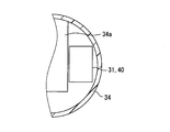
抑制構造は、吸入ハウジング34に一体に設けられ、電気的フィルタ部品40の底面と吐出経路42との間に隙間を形成する段差部71によって実現される。換言すると、電気的フィルタ部品40の設置場所に段差を設けている。これによって吸入ハウジング34と電気的フィルタ部品40の接触面積を少なくし、吸入ハウジング34と電気的フィルタ部品40との間に空気層が形成できる形状となっている。
これによって電気的フィルタ部品40と吐出経路42との間に、段差部71によって空気層が形成されるので、吐出経路42からの伝熱を抑制することができる。このように吸入ハウジング34に段差部71を設けることによって、抑制構造を実現することができる。したがって電気的フィルタ部品40の形状を変更することなく、電気的フィルタ部品40の温度上昇の抑制を実現することができる。
(第5実施形態)
次に、本開示の第5実施形態に関して、図7を用いて説明する。本実施形態では、抑制構造が吸入ハウジング34に設けられている点に特徴を有する。また図7では、理解を容易にするためモータハウジング21の外観を示している。
次に、本開示の第5実施形態に関して、図7を用いて説明する。本実施形態では、抑制構造が吸入ハウジング34に設けられている点に特徴を有する。また図7では、理解を容易にするためモータハウジング21の外観を示している。
抑制構造は、吸入ハウジング34に別体に設けられ、電気的フィルタ部品40の底面と吐出経路42との間に隙間を形成する台座部72によって実現される。吸入ハウジング34には、電気的フィルタ部品40を収容する溝73が形成されている。そして溝73の底には、台座部72が設けられている。台座部72は、電気的フィルタ部品40を設置する土台となる金属板74と、金属板74を支持する支柱75とによって構成される。支柱75は、根本が吸入ハウジング34にねじなどによって固定されている。
これによって電気的フィルタ部品40と吐出経路42との間に、台座部72によって空気層が形成されるので、吐出経路42からの伝熱を抑制することができる。このように吸入ハウジング34に台座部72を設けることによって、抑制構造を実現することができる。また土台の金属板74を通して熱を拡散できるため、さらなる温度上昇の抑制効果を奏することができる。
(第6実施形態)
次に、本開示の第6実施形態に関して、図8を用いて説明する。本実施形態では、抑制構造が吸入ハウジング34に設けられている点に特徴を有する。また図8では、理解を容易にするためモータハウジング21の外観を示している。
次に、本開示の第6実施形態に関して、図8を用いて説明する。本実施形態では、抑制構造が吸入ハウジング34に設けられている点に特徴を有する。また図8では、理解を容易にするためモータハウジング21の外観を示している。
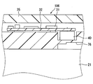
抑制構造は、吸入ハウジング34に形成され、電気的フィルタ部品40と吐出経路42との間の部分に内側に凹となる凹部76によって実現される。これによって圧縮機106を収納するモータハウジング21と吸入ハウジング34の電気的フィルタ部品40の設置部が接触しない。凹部76によって吸入経路34aから熱が伝わることを抑制することができる。
また凹部76によって電気的フィルタ部品40を設置する隔壁の厚さは、吸入ハウジング34の外周側(図8の右側)に比べ、吸入経路34a側が厚くなっている。これにより、低温の隔壁への熱伝導が増えるので電気的フィルタ部品40の温度上昇を抑制することができる。
本実施形態では、凹部76は吸入ハウジング34に形成されているが、吸入ハウジング34に限るものではない。凹部76は、たとえばインバータハウジング35に形成してもよく、モータハウジング21に形成してもよい。
(第7実施形態)
次に、本開示の第7実施形態に関して、図9を用いて説明する。本実施形態では、促進構造が吸入ハウジング34に設けられている点に特徴を有する。
次に、本開示の第7実施形態に関して、図9を用いて説明する。本実施形態では、促進構造が吸入ハウジング34に設けられている点に特徴を有する。
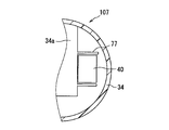
吸入ハウジング34内には、吸入経路34aを流れる流体からの熱が伝わりやすい促進リブ77が一体に設けられている。そして促進リブ77は、促進構造であって、電気的フィルタ部品40を囲んで設けられる。
換言すると、吸入ハウジング34の内、低温の吸入経路34aと電気的フィルタ部品40とを隔てる面から、電気的フィルタ部品40の吸入経路34aに近接する面と垂直な面のうち2面を囲むように促進リブ77が設けられている。促進リブ77は、吸入冷媒により冷やされた面から突出するので、冷熱が伝熱されている。したがって促進リブ77は、電気的フィルタ部品40を冷却する冷却効果を有し、電気的フィルタ部品40の温度上昇をより小さくすることができる。
(第8実施形態)
次に、本開示の第8実施形態に関して、図10~図12を用いて説明する。本実施形態の吸入ハウジング34は、第7実施形態と類似しており、本実施形態では促進リブ77とともに、放熱リブ78が設けられている。促進リブ77は、電気的フィルタ部品40の表面の少なくとも一部に接触しており、本実施形態では電気的フィルタ部品40の側面のうち2つの側面に接触している。本実施形態の促進リブ77は、電気的フィルタ部品40の第1側面と、電気的フィルタ部品40に関して第1側面の反対に位置する第2側面との2つの側面に接触してもよい。これによって側面に、吸入経路34aからの冷熱を伝熱して、電気的フィルタ部品40の温度上昇を抑制することができる。
次に、本開示の第8実施形態に関して、図10~図12を用いて説明する。本実施形態の吸入ハウジング34は、第7実施形態と類似しており、本実施形態では促進リブ77とともに、放熱リブ78が設けられている。促進リブ77は、電気的フィルタ部品40の表面の少なくとも一部に接触しており、本実施形態では電気的フィルタ部品40の側面のうち2つの側面に接触している。本実施形態の促進リブ77は、電気的フィルタ部品40の第1側面と、電気的フィルタ部品40に関して第1側面の反対に位置する第2側面との2つの側面に接触してもよい。これによって側面に、吸入経路34aからの冷熱を伝熱して、電気的フィルタ部品40の温度上昇を抑制することができる。
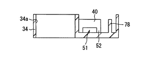
また図11および図12に示すように、吸入ハウジング34の底面であって、電気的フィルタ部品40の周囲には複数の放熱リブ78を設けている。これによって吐出経路42からの熱を、電気的フィルタ部品40以外の場所に放熱することができる。したがって吐出経路42から電気的フィルタ部品40に伝導する熱を抑制することができる。
また放熱リブ78によって吸入ハウジング34の強度を向上することができる。したがって外部からの衝撃に対して、電気的フィルタ部品40の変形ないし故障を抑制することができる。
さらに放熱リブ78は、促進リブ77および電気的フィルタ部品40と接触しない形状としている。換言すると、放熱リブ78の形状は、外部からの衝撃位置により変化し、外部からの衝撃に対して、吸入ハウジング34の強度が向上するように配置している。そして図12に示すように、放熱リブ78と電気的フィルタ部品40とが接触しないように、放熱リブ78がテーパ状の斜面を有する。これによって外部からの衝撃に対して、放熱リブ78の変形のみで抑制できる範囲を広げ、電気的フィルタ部品40の変形ないし故障を抑制することができる。
(第9実施形態)
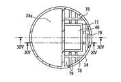
次に、本開示の第9実施形態に関して、図13~図15を用いて説明する。本実施形態の吸入ハウジング34は、第8実施形態と類似しており、本実施形態でも促進リブ77および放熱リブ78が設けられている。促進リブ77は、電気的フィルタ部品40の4つの側面を囲むように接触している。これによって電気的フィルタ部品40の側面に、吸入経路34aからの冷熱を伝熱して、電気的フィルタ部品40の温度上昇を抑制することができる。さらに電気的フィルタ部品40の位置決めが容易であるので、取り付けを容易とすることができる。
次に、本開示の第9実施形態に関して、図13~図15を用いて説明する。本実施形態の吸入ハウジング34は、第8実施形態と類似しており、本実施形態でも促進リブ77および放熱リブ78が設けられている。促進リブ77は、電気的フィルタ部品40の4つの側面を囲むように接触している。これによって電気的フィルタ部品40の側面に、吸入経路34aからの冷熱を伝熱して、電気的フィルタ部品40の温度上昇を抑制することができる。さらに電気的フィルタ部品40の位置決めが容易であるので、取り付けを容易とすることができる。
また突起である放熱リブ78は、図13に示すように、間隔を開けて複数設けられる。そして放熱リブ78の間には、図14および図15に示すように、強度向上のため繊維部材79が設けられる。繊維部材79は、たとえばアラミド繊維が用いられる。これによって隙間を吸入ハウジング34と同じ材料で充填して一体形成するよりも軽量にすることができる。また放熱リブ78が変形する空間を作ることができるので、外部からの衝撃に対して電気的フィルタ部品40の変形ないし故障を抑制することができる。
以上、本開示の好ましい実施形態について説明したが、本開示は上述した実施形態に何ら制限されることなく、本開示の主旨を逸脱しない範囲において種々変形して実施することが可能である。
上記実施形態の構造は、あくまで例示であって、本開示の範囲はこれらの記載の範囲に限定されるものではない。
第1実施形態では、圧縮機構はロータリー型であるがロータリー型に限るものではない。他の圧縮機構、たとえば斜板式であってもよく、スクロール型であってもよい。
第1実施形態では、流体は冷媒であり、冷媒用電動圧縮機10であったが、冷媒に限るものではなく、他の流体に適用してもよい。また圧縮機10は、冷凍サイクルを構成しているが、他の用途に用いてもよい。
第1実施形態では、低温部品は、電気的フィルタ部品40であるが、電気的フィルタ部品40に限るものではない。他の電子部品31を電気的フィルタ部品40に換えて、抑制構造を介して伝熱を抑制する位置に配置してもよい。また第1実施形態では電気的フィルタ部品40だけに抑制構造を適用しているが、他の電子部品31に対しても抑制構造を適用してもよい。
本開示は、実施例に準拠して記述されたが、本開示は当該実施例や構造に限定されるものではないと理解される。本開示は、様々な変形例や均等範囲内の変形をも包含する。加えて、様々な組み合わせや形態、さらには、それらに一要素のみ、それ以上、あるいはそれ以下、を含む他の組み合わせや形態をも、本開示の範疇や思想範囲に入るものである。
Claims (13)
- 吸入した流体を圧縮して吐出する圧縮部(11)と、
前記圧縮部の動力源となるモータ部(13)と、
前記モータ部を駆動し、複数の電子部品(31,40,41)を備える駆動装置(14)と、
前記駆動装置を収容する第1ケース(34,35)と、
前記圧縮部および前記モータ部を収納する第2ケース(21)と、を含み、
前記第2ケース内には、前記圧縮部によって圧縮された高温流体が流れる吐出経路(42)が設けられ、
少なくとも1つの前記電子部品(40)と前記吐出経路との間には、前記吐出経路を流れる流体からの熱が伝わることを抑制する抑制構造(51,63,71,72,76)が設けられている電動圧縮機。 - 前記第2ケース内には、前記圧縮部によって吸入された低温流体が流れる吸入経路(34a)がさらに設けられ、
前記電子部品には、発熱して高温になる高温部品(41)と、前記高温部品よりも低温で発熱する低温部品(40)とを含み、
前記高温部品と前記吸入経路との間には、前記吸入経路を流れる流体からの熱が伝わりやすい放熱構造(33)が設けられており、
前記抑制構造は、前記低温部品と前記吐出経路との間に設けられる請求項1に記載の電動圧縮機。 - 前記抑制構造は、前記電子部品の前記吐出経路側に、前記電子部品に一体に設けられる熱が伝わることを抑制する抑制部(51,63)を含む請求項1または2に記載の電動圧縮機。
- 前記抑制部は、中空の空間を形成する空間形成部(51)である請求項3に記載の電動圧縮機。
- 前記抑制部は、前記電子部品の低熱伝導率の材料を含む外殻(63)である請求項3に記載の電動圧縮機。
- 前記抑制構造は、前記第1ケースに一体に設けられ、前記電子部品の底面と前記吐出経路との間に隙間を形成する段差部(71)を含む請求項1に記載の電動圧縮機。
- 前記抑制構造は、前記第1ケースに別体に設けられ、前記電子部品の底面と前記吐出経路との間に隙間を形成する台座部(72)を含む請求項1~5のいずれか1つに記載の電動圧縮機。
- 前記抑制構造は、前記第1ケースおよび前記第2ケースの少なくともいずれか一方に形成され、前記電子部品と前記吐出経路との間の部分に内側に凹となる凹部(76)を含む請求項1~7のいずれか1つに記載の電動圧縮機。
- 前記第2ケース内には、前記圧縮部によって吸入された低温流体が流れる吸入経路(34a)がさらに設けられ、
前記第1ケース内には、前記吸入経路を流れる流体からの熱が伝わりやすい促進構造(77)が一体に設けられており、
前記促進構造は、前記電子部品を囲んで設けられる請求項1、3~8のいずれか1つに記載の電動圧縮機。 - 前記促進構造は、前記電子部品を囲んで、前記電子部品の表面の少なくとも一部に接触している請求項9に記載の電動圧縮機。
- 前記電子部品には、発熱して高温になる高温部品(41)と、前記高温部品よりも低温で発熱する低温部品(40)とを含み、
前記第1ケースの前記高温部品が設けられている部分の周囲には、突起(78)が設けられる請求項1、3~10のいずれか1つに記載の電動圧縮機。 - 前記突起は、間隔を開けて複数設けられ、
前記突起の間には、繊維部材(79)が設けられる請求項11に記載の電動圧縮機。 - 圧縮部の動力源を駆動する駆動装置を構成する電子部品であって、
外殻を構成する筐体(61)と、
前記筐体内に設けられる内部素子(62)と、
前記圧縮部によって圧縮された流体からの熱が前記内部素子に伝わることを抑制する抑制部(51,63)と、を含む電子部品。
Priority Applications (3)
| Application Number | Priority Date | Filing Date | Title |
|---|---|---|---|
| US15/542,838 US10626869B2 (en) | 2015-01-29 | 2016-01-27 | Electric compressor |
| CN201680007505.8A CN107250537B (zh) | 2015-01-29 | 2016-01-27 | 电动压缩机 |
| DE112016000526.1T DE112016000526T5 (de) | 2015-01-29 | 2016-01-27 | Elektrischer Kompressor |
Applications Claiming Priority (2)
| Application Number | Priority Date | Filing Date | Title |
|---|---|---|---|
| JP2015015856A JP6406036B2 (ja) | 2015-01-29 | 2015-01-29 | 電動圧縮機 |
| JP2015-015856 | 2015-01-29 |
Publications (1)
| Publication Number | Publication Date |
|---|---|
| WO2016121382A1 true WO2016121382A1 (ja) | 2016-08-04 |
Family
ID=56543004
Family Applications (1)
| Application Number | Title | Priority Date | Filing Date |
|---|---|---|---|
| PCT/JP2016/000392 Ceased WO2016121382A1 (ja) | 2015-01-29 | 2016-01-27 | 電動圧縮機および電子部品 |
Country Status (5)
| Country | Link |
|---|---|
| US (1) | US10626869B2 (ja) |
| JP (1) | JP6406036B2 (ja) |
| CN (1) | CN107250537B (ja) |
| DE (1) | DE112016000526T5 (ja) |
| WO (1) | WO2016121382A1 (ja) |
Families Citing this family (7)
| Publication number | Priority date | Publication date | Assignee | Title |
|---|---|---|---|---|
| JP6733575B2 (ja) * | 2017-02-23 | 2020-08-05 | 株式会社デンソー | 圧縮機及び冷凍サイクル装置 |
| DE112018000105T5 (de) * | 2017-04-27 | 2019-05-29 | Fuji Electric Co., Ltd. | Elektronisches bauelement und leistungsumwandlungseinrichtung |
| DE102018106881B4 (de) | 2018-03-22 | 2019-10-10 | Bayerische Motoren Werke Aktiengesellschaft | Absaugvorrichtung zur Kurbelgehäuseentlüftung |
| WO2023117103A1 (en) * | 2021-12-23 | 2023-06-29 | Pierburg Pump Technology Gmbh | Automotive electric liquid pump |
| FR3162483A1 (fr) * | 2024-05-23 | 2025-11-28 | Valeo Japan Co., Ltd. | Dispositif de compression d’un fluide |
| FR3162482A1 (fr) * | 2024-05-23 | 2025-11-28 | Valeo Japan Co., Ltd. | Dispositif de compression d’un fluide |
| FR3162484A1 (fr) * | 2024-05-23 | 2025-11-28 | Valeo Japan Co., Ltd. | Dispositif de compression d’un fluide |
Citations (3)
| Publication number | Priority date | Publication date | Assignee | Title |
|---|---|---|---|---|
| JP2000196010A (ja) * | 1998-12-25 | 2000-07-14 | Kyocera Corp | 配線基板モジュ―ル |
| JP2006037726A (ja) * | 2004-07-22 | 2006-02-09 | Matsushita Electric Ind Co Ltd | インバータ装置一体型電動圧縮機 |
| WO2012035767A1 (ja) * | 2010-09-16 | 2012-03-22 | パナソニック株式会社 | インバータ装置一体型電動圧縮機 |
Family Cites Families (6)
| Publication number | Priority date | Publication date | Assignee | Title |
|---|---|---|---|---|
| JPH10324144A (ja) * | 1997-05-23 | 1998-12-08 | Toyota Autom Loom Works Ltd | 車両用冷暖房装置 |
| JP3760763B2 (ja) | 2000-04-19 | 2006-03-29 | 株式会社デンソー | モータ駆動回路一体型電動圧縮装置およびそれを備えた蒸気圧縮式冷凍サイクル |
| JP2004183631A (ja) | 2002-12-06 | 2004-07-02 | Matsushita Electric Ind Co Ltd | 電動圧縮機 |
| JP2008184947A (ja) | 2007-01-29 | 2008-08-14 | Toyota Industries Corp | 電動コンプレッサ |
| JP5505352B2 (ja) * | 2011-03-31 | 2014-05-28 | 株式会社豊田自動織機 | 電動圧縮機 |
| JP5716972B2 (ja) * | 2013-02-05 | 2015-05-13 | 株式会社デンソー | 電子部品の放熱構造およびその製造方法 |
-
2015
- 2015-01-29 JP JP2015015856A patent/JP6406036B2/ja not_active Expired - Fee Related
-
2016
- 2016-01-27 WO PCT/JP2016/000392 patent/WO2016121382A1/ja not_active Ceased
- 2016-01-27 US US15/542,838 patent/US10626869B2/en not_active Expired - Fee Related
- 2016-01-27 CN CN201680007505.8A patent/CN107250537B/zh not_active Expired - Fee Related
- 2016-01-27 DE DE112016000526.1T patent/DE112016000526T5/de not_active Withdrawn
Patent Citations (3)
| Publication number | Priority date | Publication date | Assignee | Title |
|---|---|---|---|---|
| JP2000196010A (ja) * | 1998-12-25 | 2000-07-14 | Kyocera Corp | 配線基板モジュ―ル |
| JP2006037726A (ja) * | 2004-07-22 | 2006-02-09 | Matsushita Electric Ind Co Ltd | インバータ装置一体型電動圧縮機 |
| WO2012035767A1 (ja) * | 2010-09-16 | 2012-03-22 | パナソニック株式会社 | インバータ装置一体型電動圧縮機 |
Also Published As
| Publication number | Publication date |
|---|---|
| JP6406036B2 (ja) | 2018-10-17 |
| JP2016142135A (ja) | 2016-08-08 |
| CN107250537A (zh) | 2017-10-13 |
| CN107250537B (zh) | 2019-08-06 |
| US20180003179A1 (en) | 2018-01-04 |
| US10626869B2 (en) | 2020-04-21 |
| DE112016000526T5 (de) | 2017-12-28 |
Similar Documents
| Publication | Publication Date | Title |
|---|---|---|
| JP6406036B2 (ja) | 電動圧縮機 | |
| JP5687027B2 (ja) | インバータ一体型電動圧縮機 | |
| JP6167858B2 (ja) | 冷媒用電動圧縮機 | |
| US9309886B2 (en) | Inverter-integrated electric compressor | |
| JP4697148B2 (ja) | 電動圧縮機 | |
| JP5730176B2 (ja) | インバータ一体型電動圧縮機 | |
| JP5517652B2 (ja) | インバータ一体型電動圧縮機およびその組立方法 | |
| JP6222012B2 (ja) | 電子部品の冷却構造、および電動コンプレッサ | |
| CN104822941B (zh) | 电动压缩机 | |
| JP2005256700A (ja) | 電動圧縮機 | |
| JP4275393B2 (ja) | 電動ブラシレスウォータポンプ | |
| JP4699085B2 (ja) | 車両用電動圧縮機 | |
| JP2006316754A5 (ja) | ||
| KR102191125B1 (ko) | 방열 부재 조립체 및 이를 포함하는 전동식 압축기 | |
| JP2008175067A (ja) | 電動圧縮機 | |
| JP6413640B2 (ja) | 圧縮機 | |
| CN109425156B (zh) | 储液器组件、压缩机组件及空调器 | |
| JP5273232B2 (ja) | 電動圧縮機 | |
| JP2010270760A (ja) | 車両用電動圧縮機 | |
| JP2008180120A (ja) | 電動圧縮機 | |
| JP2008175068A (ja) | 電動圧縮機 | |
| JP2008163765A (ja) | 電動圧縮機 | |
| JP4830848B2 (ja) | 電動圧縮機 | |
| JP2008163767A (ja) | 電動圧縮機 | |
| JP2008163764A (ja) | 電動圧縮機 |
Legal Events
| Date | Code | Title | Description |
|---|---|---|---|
| 121 | Ep: the epo has been informed by wipo that ep was designated in this application |
Ref document number: 16742986 Country of ref document: EP Kind code of ref document: A1 |
|
| WWE | Wipo information: entry into national phase |
Ref document number: 15542838 Country of ref document: US |
|
| WWE | Wipo information: entry into national phase |
Ref document number: 112016000526 Country of ref document: DE |
|
| 122 | Ep: pct application non-entry in european phase |
Ref document number: 16742986 Country of ref document: EP Kind code of ref document: A1 |