WO2016111094A1 - 車両用複合内装部品 - Google Patents
車両用複合内装部品 Download PDFInfo
- Publication number
- WO2016111094A1 WO2016111094A1 PCT/JP2015/082961 JP2015082961W WO2016111094A1 WO 2016111094 A1 WO2016111094 A1 WO 2016111094A1 JP 2015082961 W JP2015082961 W JP 2015082961W WO 2016111094 A1 WO2016111094 A1 WO 2016111094A1
- Authority
- WO
- WIPO (PCT)
- Prior art keywords
- surface layer
- soft surface
- soft
- mating
- layer member
- Prior art date
- Legal status (The legal status is an assumption and is not a legal conclusion. Google has not performed a legal analysis and makes no representation as to the accuracy of the status listed.)
- Ceased
Links
Images






Classifications
-
- B—PERFORMING OPERATIONS; TRANSPORTING
- B60—VEHICLES IN GENERAL
- B60N—SEATS SPECIALLY ADAPTED FOR VEHICLES; VEHICLE PASSENGER ACCOMMODATION NOT OTHERWISE PROVIDED FOR
- B60N3/00—Arrangements or adaptations of other passenger fittings, not otherwise provided for
-
- B—PERFORMING OPERATIONS; TRANSPORTING
- B60—VEHICLES IN GENERAL
- B60R—VEHICLES, VEHICLE FITTINGS, OR VEHICLE PARTS, NOT OTHERWISE PROVIDED FOR
- B60R13/00—Elements for body-finishing, identifying, or decorating; Arrangements or adaptations for advertising purposes
- B60R13/02—Internal Trim mouldings ; Internal Ledges; Wall liners for passenger compartments; Roof liners
Definitions
- the present invention relates to a composite interior part for a vehicle, and more particularly, to a technique that allows easy assembly of the soft surface layer member so that the soft surface layer member does not sag or come off.
- the first member and the second member that are fitted together, and an end edge portion, and the surface of the first member in a state where the end edge portion is sandwiched between the mating surfaces of the first member and the second member
- a vehicular composite interior part including an elastically deformable soft surface layer member that covers a part or all of the above.
- the door trim described in FIG. 2 of Patent Document 1 the vehicle armrest described in FIG. 10 of Patent Document 2, and the like are examples.
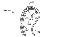
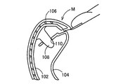
- FIG. 13 shows a cross section of a main part of a handle portion of an armrest 100 which is a kind of conventional composite interior parts for vehicles.
- the base 102 which is a relatively hard synthetic resin part molded
- the pull handle 104 which is a relatively hard synthetic resin part molded in the same manner
- the base 102 is assembled.
- the edge portion of the soft surface layer member 106 to be covered is sandwiched between the mating surfaces of the base material 102 and the pull handle 104 so that the edge portion of the soft surface layer member 106 is fixed in a state of being wound.
- the positioning projections 108 that project from the base material 102 toward the pull handle 104 side are formed through the end bent to the inside of the pull handle 104.
- the base material 102 and the pull handle 104 are positioned relative to each other by being fitted therein.
- the armrest 100 shown in FIG. 13 a portion of the edge portion of the soft surface layer member 106 that is sandwiched and wound between the mating surfaces of the base material 102 and the pull handle 104.
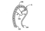
- the outer surface of the soft surface layer member 106 may have a poor appearance due to crouching or slack as shown in S of FIG.
- the edge portion of the soft surface layer member 106 may be turned up and removed.
- the occurrence of the above inconvenience is suppressed by lengthening the portion of the edge portion of the soft surface layer member 106 that is sandwiched between the mating surfaces of the base material 102 and the pull handle 104.
- the assembling property of the armrest 100 is lowered, but also the moldability of the soft surface layer member 106 is lowered when the soft surface layer member 106 is molded, and the productivity cannot be obtained. There was an inconvenience.
- the present invention has been made against the background of the above circumstances, and the purpose of the present invention is to easily assemble the first member and the second member so that the soft surface layer member does not sag or detach. It is to make it possible to do.
- the gist of the present invention includes (1) a first member and a second member that can be fitted to each other, and an edge portion, and the edge portion is the first member.
- a vehicular composite interior part comprising an elastically deformable soft surface layer member that covers part or all of the surface of the first member in a state of being sandwiched between mating surfaces of the member and the second member, (2) As the mating surfaces of the first member and the second member are brought closer to each other, the edge portion of the soft surface layer member is drawn to the back surface side of the first member to generate a tension in the soft surface layer member. It is in providing a tension generating part in at least one of the soft surface layer member and the second member.
- the tension generated in at least one of the soft surface member and the second member is generated. Since the portion pulls the edge portion of the soft surface layer member to the back surface side of the first member and generates tension in the soft surface layer member, the first member and the first member are prevented so that the soft surface layer member does not sag or come off.
- the second member can be easily assembled.
- the tension generating portion is closer to the second member side at a position adjacent to the back surface side of the first member than the mating surface of the first member in the edge portion of the soft surface layer member.
- a surface-side protrusion that is protruded and is pressed against the first member by the second member in relation to the end edge being sandwiched between the mating surfaces of the first member and the second member. is there. In this way, when the mating surfaces of the first member and the second member are brought close together, the surface-side protruding portion that protrudes from the soft surface member to the second member side.
- the tension generating portion projects from the second member toward the first member at a position adjacent to the back surface side of the first member with respect to the mating surface of the first member of the second member.
- the edge portion of the soft surface layer member is moved along the back surface of the first member in relation to the edge portion being sandwiched between the mating surfaces of the first member and the second member. It is the 2nd member side protrusion which presses to the 1st member side. In this case, when the mating surfaces of the first member and the second member are brought close together, the second member side projecting from the second member to the soft surface member side.
- the first member Since the protrusion pushes the edge portion of the soft surface layer member into the back surface side of the first member to generate tension in the soft surface layer member, the first member does not cause a sag failure or a disconnection failure of the soft surface layer member. And the second member can be easily assembled.
- the tension generating portion projects from the second member toward the first member at a position adjacent to the back surface side of the first member with respect to the mating surface of the first member of the second member.
- the edge portion of the soft surface layer member is moved along the back surface of the first member in relation to the edge portion being sandwiched between the mating surfaces of the first member and the second member. It is a level
- the stepped portion provided on the second member is the edge of the soft surface layer member. Since the portion is pushed into the back side of the first member and tension is generated in the soft surface layer member, the first member and the second member can be easily assembled so that the soft surface layer member does not sag or detach. Can be done.
- the tension generating portion is provided in a penetrating manner at a position adjacent to the rear surface side of the first member with respect to the mating surface of the first member in the edge portion of the soft surface layer member.
- the edge portion of the soft surface layer member engages with the engagement hole in relation to the end edge portion being sandwiched between the mating surfaces of the first member and the second member.
- the edge portions of the soft surface layer member are connected to the first member and the second member.
- the engaging protrusion on the second member side is engaged in the engaging hole provided in the soft surface layer member, and then the engaging position of the engaging hole is moved to the engaging base. Since the edge portion of the soft surface layer member is drawn to the back surface side of the first member by the movement of the engagement pedestal, the first member and the first member are prevented so that the soft surface layer member does not sag or come off.
- the second member can be easily assembled.
- the tension generating portion includes an engagement hole provided at a position corresponding to the mating surface of the first member in the end portion of the soft surface layer member, and the second member. It is formed on the mating surface of the first member, and an engaging projection that protrudes from the mating surface to the first member side and has an engaging slope formed toward the end edge side of the soft surface layer member toward the base end side. And a notch for avoiding interference with the engaging protrusion. According to this configuration, when the mating surfaces of the first member and the second member are brought close together, the edge portions of the soft surface layer member are connected to the first member and the second member.
- the engaging protrusion on the second member side is engaged with the engaging hole provided in the soft surface layer member, and then the engaging hole is along the engaging slope of the engaging protrusion. Since the edge portion of the soft surface layer member is drawn to the back surface side of the first member by being moved, the set of the first member and the second member so that the soft surface layer member is not slackened or detached. Can be easily attached.
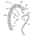
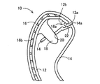
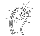
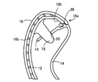
- FIG. 2 is an essential part cross-sectional view of Example 1 showing an enlarged II-II cross-sectional view of the armrest of FIG. 1, showing a state before assembly. It is principal part sectional drawing of Example 1 of FIG. 2, Comprising: The state after an assembly is shown.
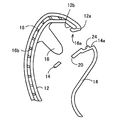
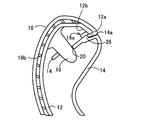
- FIG. 3 is a cross-sectional view of a main part of Example 2 showing an enlarged II-II sectional view of the armrest of FIG. 1, showing a state before assembly. It is principal part sectional drawing of Example 2 of FIG. 4, Comprising: The state after an assembly is shown.
- FIG. 2 is an essential part cross-sectional view of Example 1 showing an enlarged II-II cross-sectional view of the armrest of FIG. 1, showing a state before assembly.
- FIG. 3 is a cross-sectional view of a main part of Example 2 showing an enlarged II-II sectional view of the armrest of FIG. 1, showing a state before assembly.
- FIG. 4 Comprising: The state after an assembly is shown.
- FIG. 4 is a cross-sectional view of a main part of Example 3 showing an enlarged II-II sectional view of the armrest of FIG. 1, showing a state before assembly. It is principal part sectional drawing of Example 3 of FIG. 6, Comprising: The state after an assembly is shown.
- FIG. 10 is a cross-sectional view of a main part of Example 4 showing an enlarged view taken along the line II-II of the armrest of FIG. 1, showing a state before assembly. It is principal part sectional drawing of Example 4 of FIG. 8, Comprising: The state after an assembly is shown.
- FIG. 10 is a cross-sectional view of the main part of Example 5 showing an enlarged II-II sectional view of the armrest of FIG. 1, showing a state before assembly.
- Example 5 of FIG. 10 Comprising: The state after an assembly is shown. It is a perspective view of Example 5 shown in FIG. It is principal part sectional drawing of the conventional armrest, Comprising: The state after an assembly is shown. It is principal part sectional drawing of the conventional armrest of FIG. 13, Comprising: It is a figure which shows the example in which the external appearance defect generate
- FIG. 1 is a perspective view schematically showing a configuration of an armrest 10 which is an example of a composite interior part for a vehicle which is a preferred embodiment of the present invention, and shows a design surface side thereof.
- the armrest 10 of the present embodiment is a plate-like member attached to, for example, an inner panel, that is, a door inner plate in a right door of an automobile, and corresponds to a part of a vehicle door trim provided on the design surface side of the door.
- the design surface refers to the surface of the armrest 10 that is visible from the inside of the vehicle, and the design surface corresponds to the vehicle interior (vehicle compartment) side of the vehicle composite interior component 10.
- the counter-design surface means a surface opposite to the design surface, that is, a surface that cannot be visually recognized from the inside of the vehicle, and the counter-design surface side corresponds to the vehicle exterior side of the vehicle.
- the present invention includes, for example, a luggage side trim, an instrument panel, an armrest, and an ornament attached to them. It is suitably applied to a composite interior part for a vehicle.
- FIGS. 2 and 3 are enlarged cross-sectional views of the main part showing an enlarged cross-sectional view taken along the line II-II in FIG.
- FIG. 2 shows a state before assembly
- FIG. 3 shows a state after assembly.
- the armrest 10 is a relatively hard synthetic resin part molded in the same manner as the base 12 which is a molded relatively hard synthetic resin part.
- the pull handle 14 When the pull handle 14 is fitted and assembled, the end portion of the soft surface layer member 16 that covers the base material 12 is sandwiched between the mating surface 12a of the base material 12 and the mating surface 14a of the pull handle 14, thereby providing a soft surface layer member.
- the 16 edge portions 16a are fixed in a wound state.
- the positioning protrusion 18 projecting from the base material 12 toward the pull handle 14 is fitted into a positioning hole 20 formed so as to penetrate the end bent to the inside of the pull handle 14.
- the substrate 12 and the pull handle 14 are positioned relative to each other.
- the base 12 and the pull handle 14 are made of a relatively hard synthetic resin material such as polypropylene resin, hard polyvinyl chloride, ABS resin, AS resin, or the like.
- the substrate 12 corresponds to the first member
- the pull handle 14 corresponds to the second member.
- the soft surface layer member 16 has a cushioning property by forming a large number of elastic protrusions 16b protruding toward the base material 12 on the surface on the side opposite to the design surface, and these elastic protrusions function as a cushion portion. .
- the soft surface layer member 16 is attached so as to cover the surface of the base material 12 (the surface on the design surface side) so as to be located on the vehicle inner side (vehicle compartment side).
- the soft surface layer member 16 is made of, for example, urethane foam, sponge rubber or the like that generates a predetermined elasticity or a cushioning property that is elastically deformed by being pressed from a synthetic resin material such as polypropylene resin or urethane resin. It may be used instead of or in addition to the elastic protrusion.
- the soft skin material 16 is made of a relatively soft (flexible) material that can be easily elastically deformed by the force of the operator's fingers.
- it is composed of a soft synthetic resin material, and various thermoplastic resin materials such as soft polyvinyl chloride, styrene-based, olefin-based, and polyester-based materials are preferably used.
- it may be composed of various skin materials such as woven fabrics, nonwoven fabrics, knitted fabrics, vinyl chloride, soft films, natural materials such as wool and cowhide.
- the armrest 10 is a soft surface layer member that covers the base material 12 in a state where the folded end edge portion 16 a of the soft surface layer member 16 is wound around the mating surface 12 a that is an edge of the base material 12.
- 16 is provided with a structure in which the end edges of 16 are sandwiched between the mating surface 12a of the base 12 and the mating surface 14a of the pull handle 14.
- the end of the soft surface layer member 16 is located at a position adjacent to the mating surface 12 a of the base material 12 on the back surface 12 b side of the base material 12 in the folded edge 16 a of the soft surface layer member 16.
- a surface layer side protrusion 22 that is pressed toward the base material 12 by the pull handle 14 is provided.
- the surface layer side protrusion 22 pushes the edge 16a of the soft surface layer member 16 toward the back surface 12b side of the base material 12 when the base material 12 and the pull handle 14 are assembled, and generates tension on the soft surface layer member 16. It functions as a generator.
- the end surface 16a of the soft surface layer member 16 protrudes from the end edge portion 16a toward the pull handle 14, and the end surface 16a of the soft surface layer member 16 is connected to the mating surface 12a of the base 12 and the pull handle.
- the surface layer side protrusions 22 pressed against the base material 12 side by the pull handle 14 are related to the base material 12 in the folded edge 16 a of the soft surface layer member 16. 2 to 3, the mating surface 12 a of the base material 12 and the pull handle 14 are aligned as shown in FIGS. 2 to 3.
- the surface layer side protrusions 22 protruding from the soft surface layer member 16 to the pull handle 14 side are edge portions 16 of the soft surface layer member 16. Is pushed into the back surface 12b side of the base material 12 and the soft surface layer member 16 is pulled in as shown by the broken arrow in FIG. 3 to generate tension in the soft surface layer member 16.
- the soft surface layer member 16 can be easily assembled so as not to occur.
- the surface layer-side protrusion 22 exists on the inner side from the pinching position between the mating surface 12a of the base material 12 and the mating surface 14a of the pull handle 14, so that the soft surface layer member 16 Since the pull-out load is increased, the edge 16a of the soft surface layer member 16 is firmly fixed as compared with the conventional structure shown in FIGS.
- FIGS. 4 and 5 are enlarged partial sectional views showing the vicinity of the terminal portion (end on the vehicle upper side) in another embodiment of the armrest 10, and FIG. 4 shows a state before assembly. Indicates the state after assembly.
- the end edge portion 16 a of the soft surface layer member 16 is sandwiched between the mating surface 12 a of the base material 12 and the mating surface 14 a of the pull handle 14.
- the pull handle side protrusion 24 that presses the end edge portion 16 a of the soft surface layer member 16 toward the base material 12 side along the back surface 12 b of the base material 12 is formed on the mating surface 14 a of the pull handle 14.
- the pull handle 14 protrudes from the pull handle 14 toward the base 12 at a position adjacent to the back side of the base 12.
- the pull handle side protrusion 24 corresponds to the second member side protrusion, and when the base member 12 and the pull handle 14 are assembled, the edge 16a of the soft surface layer member 16 is used as the back surface 12b of the base member 12. It functions as a tension generating part that is pushed in to the side to generate tension on the soft surface layer member 16.
- the pull handle 14 protrudes toward the base material 12, and the edge 16 a of the soft surface layer member 16 is formed on the mating surface 12 a of the base material 12 and the mating surface 14 a of the pull handle 14.
- the pull handle side protrusion 24 that presses the end edge portion 16 a of the soft surface layer member 16 along the back surface 12 b of the base material 12 toward the base material 12 in association with the clamping. Since the surface 14a is provided at a position adjacent to the back surface side of the base material 12 more than that, as shown in FIGS. 4 to 5, the mating surface 12a of the base material 12 and the mating surface 14a of the pull handle 14 As shown in FIG.
- the pull handle side protrusion 24 pushes the edge 16a of the soft surface layer member 16 into the back side of the base material 12 and is shown by the broken line arrow in FIG. Since the soft surface layer member 16 is pulled in and tension is generated in the soft surface layer member 16, the base material 12 and the pull handle 14 can be easily assembled so that the soft surface layer member 16 does not sag or detach. it can.
- the area around the base material 12 of the soft surface member 16 increases due to the presence of the pull handle side protrusion 24, and the pulling load of the soft surface member 16 is increased.
- the end edge 16 a of the soft surface layer member 16 is firmly fixed.
- FIGS. 6 and 7 are enlarged partial sectional views showing the vicinity of the end portion (the end portion on the vehicle upper side) in another embodiment of the armrest 10, and FIG. 6 shows a state before assembly. Indicates the state after assembly.
- the edge 16 a of the soft surface layer member 16 is sandwiched between the mating surface 12 a of the base material 12 and the mating surface 14 a of the pull handle 14.
- the step portion 26 that presses the edge 16 a of the soft surface layer member 16 toward the base 12 along the back surface 12 b of the base 12 is the base 12 of the mating surface 12 a of the base 12 of the pull handle 14.
- the step portion 26 is a tension generating portion that pushes the edge 16a of the soft surface layer member 16 toward the back surface 12b of the base material 12 to generate tension on the soft surface layer member 16 when the base material 12 and the pull handle 14 are assembled. Is functioning as
- the soft surface layer member 16 is associated with the end edge portion 16a of the soft surface layer member 16 being sandwiched between the mating surface 12a of the base material 12 and the mating surface 14a of the pull handle 14.
- the step portion 26 that presses the edge 16a of the base material 12 along the back surface 12b of the base material 12 toward the base material 12 side is adjacent to the back surface 12b side of the base material 12 of the mating surface 12a of the base material 12 of the pull handle 14. Since the pull handle 14 protrudes from the pull handle 14 to the base 12 side, the mating surface 12a of the base 12 and the mating surface 14a of the pull handle 14 are brought close to each other as shown in FIGS.
- the stepped portion 26 pushes the edge 16a of the soft surface layer member 16 into the back surface side of the base material 12, pulls in the soft surface layer member 16 as shown by the dashed arrow in FIG. Since generating a tension in the surface layer member 16, it is possible to easily perform the assembling of the base 12 and the pull handle 14 as sagging defects and off failure of the soft surface layer member 16 does not occur.
- the area around the base material 12 of the soft surface layer member 16 is increased due to the presence of the stepped portion 26 and the pulling load of the soft surface layer member 16 is increased.
- the edge 16a of the soft surface layer member 16 is firmly fixed.
- FIG. 8 and 9 are enlarged partial sectional views showing the vicinity of a terminal portion (an end portion on the vehicle upper side) in another embodiment of the armrest 10, and FIG. 8 shows a state before assembly. Indicates the state after assembly.
- the edge 16 a of the soft surface layer member 16 is positioned closer to the back surface 12 b side of the base material 12 than the mating surface 12 a of the base material 12.
- An engagement hole 28 provided therethrough, an engagement pedestal 30 that protrudes at a position closer to the base material 12 than the mating surface 12a of the base material 12 of the pull handle 14 inside the base material 12;
- the end 16a of the soft surface layer member 16 is protruded from the engagement base 30 toward the base material 12 and is related to being sandwiched between the mating surface 12a of the base material 12 and the mating surface 14a of the pull handle 14.
- An engagement protrusion 32 that engages with the engagement hole 28 and draws the end edge portion 16a of the soft surface layer member 16 toward the back surface 12b of the base 12 is provided.
- the engagement hole 28, the engagement pedestal 30, and the engagement protrusion 32 are formed so that the edge 16 a of the soft surface layer member 16 is attached to the back surface of the substrate 12 when the substrate 12 and the pull handle 14 are assembled. It functions as a tension generating part that is pushed into the 12b side to generate tension in the soft surface layer member 16.
- the engagement provided through the position adjacent to the back surface 12b side of the base material 12 rather than the mating surface 12a of the base material 12 in the end edge portion 16a of the soft surface layer member 16.
- a hole 28 an engagement base 30 projecting from the mating surface 12 a of the pull handle 14 to the base 12 side inside the base 12, and the engagement base 30 to the base 12 and protrudes toward the side 12, and engages with the engagement hole 28 in relation to the end edge portion 16a of the soft surface layer member 16 being sandwiched between the mating surface 12a of the base 12 and the mating surface 14a of the pull handle 14.
- the engaging protrusion 32 that pulls the edge 16a of the soft surface layer member 16 toward the back surface 12b of the base 12 functions as a tension generating portion, the mating surface 12a of the base 12 and the pull handle 14 Of the mating surfaces 14a When the end edges 16a of the soft surface layer member 16 are clamped between the mating surface 12a of the base material 12 and the mating surface 14a of the pull handle 14, After 32 is engaged in the engagement hole 28 provided in the soft surface layer member 16, the engagement position of the engagement hole 28 is moved onto the engagement pedestal 30 and is indicated by the broken arrow in FIG.
- the soft surface layer member 16 is not sagging or detached.
- the base member 12 and the pull handle 14 can be easily assembled so as not to occur.
- the pulling load of the soft surface layer member 16 is obtained by engaging the engagement protrusion 32 on the pull handle 14 side in the engagement hole 28 provided in the soft surface layer member 16. Therefore, the edge 16a of the soft surface layer member 16 is firmly fixed as compared with the conventional structure shown in FIGS.
- FIG. 11 and FIG. 12 are enlarged views of the main part showing the vicinity of the terminal portion (the end on the vehicle upper side) in another embodiment of the armrest 10, and FIG. 10 and FIG. FIG. 12 is a cross-sectional view (cross-sectional view taken along the line XX in FIG. 12) of the engagement protrusion 38 showing the state and the state after assembly, and FIG. 12 is a perspective view showing the state after assembly.
- the end portion 16 a of the soft surface layer member 16 is provided through the position corresponding to the mating surface 12 a of the base material 12.
- the first engagement is formed with an engagement hole 34 and an engagement slope 36 that protrudes from the mating surface 14a of the pull handle 14 toward the base material 12 and toward the end edge of the soft surface layer member 16 toward the base end side.
- a second engagement protrusion 42 is provided which protrudes toward the mating surface 14a and protrudes with an amount of protrusion substantially corresponding to the thickness of the soft surface layer member 16 and engages with the engagement hole 34.
- the engagement hole 34, the engagement inclined surface 36, the first engagement protrusion 38, the notch 40, and the second engagement protrusion 42 are formed on the soft surface layer when the base material 12 and the pull handle 14 are assembled.
- the end 16a of the member 16 is pushed into the back surface 12b side of the substrate 12 to function as a tension generating unit that generates tension on the soft surface layer member 16.
- the engagement between the engagement hole 34 provided at a position corresponding to the mating surface 12a of the substrate 12 in the end edge portion 16a of the soft surface layer member 16 and the pull handle 14 is aligned.
- a first engagement protrusion 38 formed with an engagement slope 36 that protrudes from the surface 14a toward the base 12 and toward the edge of the soft surface layer member 16 toward the base end, and a mating surface 12a of the base 12
- a notch 40 that receives the engaging projection 38 and avoids interference with the engaging projection 38, and faces the mating surface 12 a of the pull handle 14 from the mating surface 12 a of the base 12 on both sides of the notch 40.
- the mating surface 12a of the base 12 and the mating surface 14a of the pull handle 14 are in contact with each other.
- the edge 16a of the soft surface layer member 16 is sandwiched between the mating surface 12a of the base material 12 and the mating surface 14a of the pull handle 14 when assembled to each other, the first on the pull handle 14 side.
- the first engaging protrusion 38 is moved to the base end side, and the edge 16a of the soft surface layer member 16 is moved by the relative movement of the first engaging protrusion 38 toward the base member 12 as shown by the broken arrow in FIG. Is pulled to the back surface 12b side of the base material 12, so that the base material 12 and the pull handle 14 can be easily assembled so that the soft surface layer member 16 does not sag or detach.
- the first engagement projecting from the mating surface 14a of the pull handle 14 in the engagement hole 34 provided through the end edge portion 16a of the soft surface layer member 16. Since the mating protrusions 38 are engaged to increase the pull-out load of the soft surface layer member 16, the edge 16a of the soft surface layer member 16 is firmly fixed as compared with the conventional structure shown in FIGS. .
- the protrusion 12 protrudes from the mating surface 12a of the base material 12 to the mating surface 14a of the pull handle 14 with a projection amount substantially corresponding to the thickness of the soft surface layer member 16. Since the second engagement protrusion 42 that engages with the engagement hole 34 is provided, there is an advantage that the edge 16a of the soft surface layer member 16 is more firmly fixed.
Landscapes
- Engineering & Computer Science (AREA)
- Mechanical Engineering (AREA)
- Transportation (AREA)
- Vehicle Interior And Exterior Ornaments, Soundproofing, And Insulation (AREA)
- Passenger Equipment (AREA)
- Vehicle Step Arrangements And Article Storage (AREA)
Abstract
軟質表層部材のたるみ不良や外れ不良が発生しないように基材12とプルハンドル14の組付けを容易に行なうようにする。 軟質表層部材16の端縁部16aからプルハンドル14側へ突設されて、プルハンドル14により基材12側へ押圧される表層側突部22が、軟質表層部材16の折り返し端縁部16aのうち基材12の合わせ面12aにそれよりも基材12の裏面12b側に隣接する位置に設けられている。基材12の合わせ面12aとプルハンドル14の合わせ面14aとが互いに接近させられるとき、軟質表層部材16からプルハンドル14側へ突設された表層側突部22が軟質表層部材16の端縁部16aを基材12の裏面12b側に押し込み、軟質表層部材16に張力を発生させるので、軟質表層部材16のたるみ不良や外れ不良が発生しないように基材12とプルハンドル14の組付けを容易に行なうことを可能とする。
Description
本発明は、車両用複合内装部品に関し、特に、軟質表層部材のたるみ不良や外れ不良が発生しないようにその軟質表層部材の組付けを容易に行なうことを可能とする技術に関する。
相互に嵌め着けられる第1部材および第2部材と、端縁部を有し、前記端縁部が前記第1部材と第2部材との合わせ面に挟持された状態で前記第1部材の表面の一部または全部を覆う弾性変形可能な軟質表層部材とを、備える車両用複合内装部品が知られている。例えば、特許文献1の図2に記載されたドアトリムや、特許文献2の図10等に記載された車両用アームレストがその一例である。
図13は、従来の車両用複合内装部品の一種であるアームレスト100のハンドル部分の要部断面を示している。型成形された比較的硬質の合成樹脂製部品である基材102に、それと同様に型成形された比較的硬質の合成樹脂製部品であるプルハンドル104を嵌め合わせて組み付けるとき、基材102を覆う軟質表層部材106の端縁部が基材102とプルハンドル104との合わせ面で挟持されることにより、軟質表層部材106の端縁部が巻き込まれた状態で固定されるようになっている。なお、図13の要部断面図において、基材102からプルハンドル104側へ突設された位置決め突起108が、プルハンドル104の内側に曲げられた端部に貫通して形成された位置決め穴110内に嵌合されることにより、基材102およびプルハンドル104の相互が位置決めされるようになっている。
ところで、上記従来の車両用複合内装部品、たとえば図13に示されるアームレスト100では、軟質表層部材106の端縁部のうち基材102とプルハンドル104との合わせ面で挟持されて巻き込まれた部分が短いことから、プルハンドル104に掛けた指の爪が引っかかると、図14のSに示すように軟質表層部材106の端縁部にしゃくれ或いはたるみによる外観不良が発生したり、図15のMに示すように軟質表層部材106の端縁部がめくれて外れてしまう可能性があった。
これに対して、軟質表層部材106の端縁部のうち、基材102とプルハンドル104との合わせ面で挟持されて巻き込まれた部分を長くすることで、上記の不都合の発生を抑制することが考えられるが、アームレスト100の組み付け性が低下するだけでなく、軟質表層部材106を型成形するときに軟質表層部材106の金型からの離型性が低下してその生産性が得られないという、不都合があった。
本発明は、以上の事情を背景として為されたものであり、その目的とするところは、軟質表層部材のたるみ不良や外れ不良が発生しないように第1部材と第2部材の組付けを容易に行なうことを可能とすることにある。
斯かる目的を達成するために、本発明の要旨とするところは、(1)相互に嵌め着けられる第1部材および第2部材と、端縁部を有し、前記端縁部が前記第1部材と第2部材との合わせ面に挟持された状態で前記第1部材の表面の一部または全部を覆う弾性変形可能な軟質表層部材とを備える車両用複合内装部品であって、(2)前記第1部材および第2部材の相互の合わせ面が互いに接近させられることに伴って前記軟質表層部材の端縁部を前記第1部材の裏面側に引き込んで前記軟質表層部材に張力を発生させる張力発生部を、前記軟質表層部材および前記第2部材の少なくとも一方に備えることにある。
このようにすれば、前記第1部材および第2部材の相互の合わせ面が互いに接近させられることにより相互に組み付けられるとき、前記軟質表層部材および前記第2部材の少なくとも一方に備えられた張力発生部が前記軟質表層部材の端縁部を前記第1部材の裏面側に引き込んで前記軟質表層部材に張力を発生させるので、軟質表層部材のたるみ不良や外れ不良が発生しないように第1部材と第2部材の組付けを容易に行なうことができる。
ここで、好適には、前記張力発生部は、前記軟質表層部材の端縁部のうち前記第1部材の合わせ面よりも前記第1部材の裏面側に隣接する位置に前記第2部材側へ突設され、前記端縁部が前記第1部材と第2部材との合わせ面に挟持されることに関連して、前記第2部材により前記第1部材側へ押圧される表層側突部である。このようにすれば、前記第1部材および第2部材の相互の合わせ面が互いに接近させられることにより相互に組み付けられるとき、前記軟質表層部材から第2部材側へ突設された表層側突部が前記軟質表層部材の端縁部を前記第1部材の裏面側に押し込んで前記軟質表層部材に張力を発生させるので、軟質表層部材のたるみ不良や外れ不良が発生しないように第1部材と第2部材の組付けを容易に行なうことができる。
また、好適には、前記張力発生部は、前記第2部材の前記第1部材の合わせ面よりも前記第1部材の裏面側に隣接する位置に前記第2部材から前記第1部材側へ突設され、前記端縁部が前記第1部材と第2部材との合わせ面に挟持されることに関連して、前記軟質表層部材の端縁部を、前記第1部材の裏面に沿って前記第1部材側へ押圧する第2部材側突部である。
このようにすれば、前記第1部材および第2部材の相互の合わせ面が互いに接近させられることにより相互に組み付けられるとき、前記第2部材から軟質表層部材側へ突設された第2部材側突部が前記軟質表層部材の端縁部を前記第1部材の裏面側に押し込んで前記軟質表層部材に張力を発生させるので、軟質表層部材のたるみ不良や外れ不良が発生しないように第1部材と第2部材の組付けを容易に行なうことができる。
このようにすれば、前記第1部材および第2部材の相互の合わせ面が互いに接近させられることにより相互に組み付けられるとき、前記第2部材から軟質表層部材側へ突設された第2部材側突部が前記軟質表層部材の端縁部を前記第1部材の裏面側に押し込んで前記軟質表層部材に張力を発生させるので、軟質表層部材のたるみ不良や外れ不良が発生しないように第1部材と第2部材の組付けを容易に行なうことができる。
また、好適には、前記張力発生部は、前記第2部材の前記第1部材の合わせ面よりも前記第1部材の裏面側に隣接する位置に前記第2部材から前記第1部材側へ突設され、前記端縁部が前記第1部材と第2部材との合わせ面に挟持されることに関連して、前記軟質表層部材の端縁部を、前記第1部材の裏面に沿って前記第1部材側へ押圧する段差部である。このようにすれば、前記第1部材および第2部材の相互の合わせ面が互いに接近させられることにより相互に組み付けられるとき、前記第2部材に設けられた段差部が前記軟質表層部材の端縁部を前記第1部材の裏面側に押し込んで前記軟質表層部材に張力を発生させるので、軟質表層部材のたるみ不良や外れ不良が発生しないように第1部材と第2部材の組付けを容易に行なうことができる。
また、好適には、前記張力発生部は、前記軟質表層部材の端縁部のうち前記第1部材の合わせ面よりも前記第1部材の裏面側に隣接する位置に貫通して設けられた係合穴と、前記第1部材の内側であって前記第2部材の前記第1部材の合わせ面よりも前記第1部材側に位置する係合台座と、該係合台座から前記第1部材側へ突設され、前記端縁部が前記第1部材と第2部材との合わせ面に挟持されることに関連して、前記係合穴と係合し、且つ前記軟質表層部材の端縁部を前記第1部材の裏面側へ引き込む係合突起とを、含む。このようにすれば、前記第1部材および第2部材の相互の合わせ面が互いに接近させられることにより相互に組み付けられるとき、前記軟質表層部材の端縁部が前記第1部材と第2部材との合わせ面に挟持される過程で、第2部材側の係合突起が軟質表層部材に設けられた係合穴内に係合させられた後、係合穴の係合位置が前記係合台座へ移動させられ、その係合台座の移動により前記軟質表層部材の端縁部が前記第1部材の裏面側へ引き込まれるので、軟質表層部材のたるみ不良や外れ不良が発生しないように第1部材と第2部材の組付けを容易に行なうことができる。
また、好適には、前記張力発生部は、前記軟質表層部材の端縁部のうち前記第1部材の合わせ面に対応する位置に貫通して設けられた係合穴と、前記第2部材の合わせ面から前記第1部材側へ突設され、基端側へ向かうほど前記軟質表層部材の端縁側へ向かう係合斜面が形成された係合突起と、前記第1部材の合わせ面に形成され、前記係合突起との干渉を回避する切欠きとを、含む。このようにすれば、前記第1部材および第2部材の相互の合わせ面が互いに接近させられることにより相互に組み付けられるとき、前記軟質表層部材の端縁部が前記第1部材と第2部材との合わせ面に挟持される過程で、第2部材側の係合突起が軟質表層部材に設けられた係合穴内に係合させられた後、係合穴が係合突起の係合斜面に沿って移動させられることにより前記軟質表層部材の端縁部が前記第1部材の裏面側へ引き込まれるので、軟質表層部材のたるみ不良や外れ不良が発生しないように第1部材と第2部材の組付けを容易に行なうことができる。
以下、本発明の好適な実施例を図面に基づいて詳細に説明する。以下の説明に用いる図面において、各部の寸法比等は必ずしも正確には描かれていない。
図1は、本発明の好適な実施例である車両用複合内装部品の一例であるアームレスト10の構成を概略示す斜視図であり、その意匠面側を示している。本実施例のアームレスト10は、例えば自動車の右側ドアにおけるインナーパネルすなわちドア内板に取り付けられる板状の部材であり、前記ドアの意匠面側に設けられる車両用ドアトリムの一部に相当する。本実施例において、意匠面とは、アームレスト10の車内から視認できる側の面をいうものであり、意匠面側とは、車両用複合内装部品10の車内(車室)側に相当する。反意匠面とは、前記意匠面の反対側の面すなわち車内から視認できない側の面をいうものであり、反意匠面側とは、車両の車外側に相当する。本実施例においては、ドア内板に取り付けられるアームレスト10に本発明が適用された例について説明するが、本発明は、例えば、ラゲージサイドトリム、インストルメントパネル、アームレスト、それらに取り付けられるオーナメント等の車両用複合内装部品に好適に適用される。
図2および図3は、図1のII-II視断面を拡大して示す要部拡大断面図、すなわちアームレスト10における端末部(車両上方側の端部)付近を拡大して示す部分断面図であって、図2は組み立て前の状態を示し、図3は組み立て後の状態を示している。図2および図3に示すように、アームレスト10は、型成形された比較的硬質の合成樹脂製部品である基材12に、それと同様に型成形された比較的硬質の合成樹脂製部品であるプルハンドル14を嵌め合わせて組み付けるとき、基材12を覆う軟質表層部材16の端縁部が基材12の合わせ面12aとプルハンドル14の合わせ面14aとで挟持されることにより、軟質表層部材16の端縁部16aが巻き込まれた状態で固定されるようになっている。なお、基材12からプルハンドル14側へ突設された位置決め突起18が、プルハンドル14の内側に曲げられた端部に貫通して形成された位置決め穴20内に嵌合されることにより、基材12およびプルハンドル14の相互が位置決めされるようになっている。
基材12およびプルハンドル14は、例えば、ポリプロピレン樹脂、硬質ポリ塩化ビニル、ABS樹脂、AS樹脂等の比較的硬質の合成樹脂材料から構成されている。本実施例では、基材12が第1部材に、プルハンドル14が第2部材に対応している。
軟質表層部材16は、その反意匠面側の面に、基材12へ向かって突き出す多数の弾性突起16bが形成され、それら弾性突起がクッション部として機能することで、クッション性を有している。軟質表層部材16は、車内側(車室側)に位置するように、基材12の表面(意匠面側の面)を覆うように貼り付けされている。軟質表層部材16は、例えば、ポリプロピレン樹脂、ウレタン樹脂等の合成樹脂材料から、所定の弾力性すなわち押圧されることで弾性変形させられるクッション性を発生させるウレタンフォーム、スポンジゴム等が、上記多数の弾性突起に替えて、或いは加えて用いられてもよい。
軟質表皮材16は、作業者の指による力等により容易に弾性変形させられる比較的軟質(可撓性)の材料から構成されたものである。好適には、軟質合成樹脂材料から構成されたものであり、例えば、軟質ポリ塩化ビニルやスチレン系、オレフィン系、ポリエステル系等の各種の熱可塑性樹脂材料が好適に用いられる。或いは、織布や不織布、編布、塩化ビニル、軟質フィルム、ウールや牛革をはじめとする天然素材等、種々の表皮材料から構成されたものであってもよい。
図2および図3に示すように、アームレスト10は、基材12の端縁である合わせ面12aを軟質表層部材16の折り返し端縁部16aが巻き込んだ状態で、基材12を覆う軟質表層部材16の端縁部が基材12の合わせ面12aとプルハンドル14の合わせ面14aとで挟持される構造を備えている。
図2に示すように、軟質表層部材16の折り返し端縁部16aのうち基材12の合わせ面12aにそれよりも基材12の裏面12b側に隣接する位置には、軟質表層部材16の端縁部16aからプルハンドル14側へ突設されて、軟質表層部材16の端縁部16aが基材12の合わせ面12aとプルハンドル14の合わせ面14aとに挟持されることに関連して、プルハンドル14により基材12側へ押圧される表層側突部22が、設けられている。この表層側突部22が、基材12とプルハンドル14との組み立てに際して、軟質表層部材16の端縁部16aを基材12の裏面12b側に押し込んで軟質表層部材16に張力を発生させる張力発生部として機能している。
本実施例のアームレスト10によれば、軟質表層部材16の端縁部16aからプルハンドル14側へ突設されて、軟質表層部材16の端縁部16aが基材12の合わせ面12aとプルハンドル14の合わせ面14aとに挟持されることに関連して、プルハンドル14により基材12側へ押圧される表層側突部22が、軟質表層部材16の折り返し端縁部16aのうち基材12の合わせ面12aにそれよりも基材12の裏面12b側に隣接する位置に設けられていることから、図2から図3に示すように、基材12の合わせ面12aとプルハンドル14の合わせ面14aとが互いに接近させられることにより相互に組み付けられるとき、軟質表層部材16からプルハンドル14側へ突設された表層側突部22が軟質表層部材16の端縁部16aを基材12の裏面12b側に押し込み、図3の破線の矢印に示すように軟質表層部材16を引き込んで、軟質表層部材16に張力を発生させるので、軟質表層部材16のたるみ不良や外れ不良が発生しないようにその軟質表層部材16の組付けを容易に行なうことができる。
また、本実施例のアームレスト10によれば、基材12の合わせ面12aとプルハンドル14の合わせ面14aとの挟圧位置から内側に表層側突部22が存在することによって軟質表層部材16の引き抜き荷重が高められるので、図13から図15に示す従来の構造に比較して、軟質表層部材16の端縁部16aが強固に固定される。
次に、本発明の他の実施例を説明する。なお、以下の実施例の説明では、実施例相互間で共通する部分には同一の符号を付して説明を省略する。
図4および図5は、アームレスト10の他の実施例における端末部(車両上方側の端部)付近を拡大して示す部分断面図であって、図4は組み立て前の状態を示し、図5は組み立て後の状態を示している。図4および図5に示すように、本実施例のアームレスト10では、軟質表層部材16の端縁部16aが基材12の合わせ面12aとプルハンドル14の合わせ面14aとに挟持されることに関連して、その軟質表層部材16の端縁部16aを、基材12の裏面12bに沿って基材12側へ押圧するプルハンドル側突部24が、プルハンドル14の合わせ面14aにそれよりも基材12の裏面側に隣接する位置にプルハンドル14から基材12側へ突設されている。このプルハンドル側突部24は、第2部材側突部に対応するものであり、基材12とプルハンドル14との組み立てに際して、軟質表層部材16の端縁部16aを基材12の裏面12b側に押し込んで軟質表層部材16に張力を発生させる張力発生部として機能している。
本実施例のアームレスト10によれば、プルハンドル14から基材12側へ突設され、軟質表層部材16の端縁部16aが基材12の合わせ面12aとプルハンドル14の合わせ面14aとに挟持されることに関連して、その軟質表層部材16の端縁部16aを、基材12の裏面12bに沿って基材12側へ押圧するプルハンドル側突部24が、プルハンドル14の合わせ面14aにそれよりも基材12の裏面側に隣接する位置に設けられていることから、図4から図5に示すように、基材12の合わせ面12aとプルハンドル14の合わせ面14aとが互いに接近させられることにより相互に組み付けられるとき、プルハンドル側突部24が軟質表層部材16の端縁部16aを基材12の裏面側に押し込み、図5の破線の矢印に示すように軟質表層部材16を引き込んで、軟質表層部材16に張力を発生させるので、軟質表層部材16のたるみ不良や外れ不良が発生しないように基材12とプルハンドル14の組付けを容易に行なうことができる。
また、本実施例のアームレスト10によれば、プルハンドル側突部24の存在によって軟質表層部材16の基材12に巻きつく面積が増加して軟質表層部材16の引き抜き荷重が高められるので、図13から図15に示す従来の構造に比較して、軟質表層部材16の端縁部16aが強固に固定される。
図6および図7は、アームレスト10の他の実施例における端末部(車両上方側の端部)付近を拡大して示す部分断面図であって、図6は組み立て前の状態を示し、図7は組み立て後の状態を示している。図6および図7に示すように、本実施例のアームレスト10では、軟質表層部材16の端縁部16aが基材12の合わせ面12aとプルハンドル14の合わせ面14aとに挟持されることに関連して、軟質表層部材16の端縁部16aを基材12の裏面12bに沿って基材12側へ押圧する段差部26が、プルハンドル14の基材12の合わせ面12aの基材12の裏面12b側に隣接する位置にプルハンドル14から基材12側へ突設されている。この段差部26は、基材12とプルハンドル14との組み立てに際して、軟質表層部材16の端縁部16aを基材12の裏面12b側に押し込んで軟質表層部材16に張力を発生させる張力発生部として機能している。
本実施例のアームレスト10によれば、軟質表層部材16の端縁部16aが基材12の合わせ面12aとプルハンドル14の合わせ面14aとに挟持されることに関連して、軟質表層部材16の端縁部16aを基材12の裏面12bに沿って基材12側へ押圧する段差部26が、プルハンドル14の基材12の合わせ面12aの基材12の裏面12b側に隣接する位置にプルハンドル14から基材12側へ突設されていることから、図6から図7に示すように、基材12の合わせ面12aとプルハンドル14の合わせ面14aとが互いに接近させられることにより相互に組み付けられるとき、段差部26が軟質表層部材16の端縁部16aを基材12の裏面側に押し込み、図7の破線の矢印に示すように軟質表層部材16を引き込んで、軟質表層部材16に張力を発生させるので、軟質表層部材16のたるみ不良や外れ不良が発生しないように基材12とプルハンドル14の組付けを容易に行なうことができる。
また、本実施例のアームレスト10によれば、段差部26の存在によって軟質表層部材16の基材12に巻きつく面積が増加して軟質表層部材16の引き抜き荷重が高められるので、図13から図15に示す従来の構造に比較して、軟質表層部材16の端縁部16aが強固に固定される。
図8および図9は、アームレスト10の他の実施例における端末部(車両上方側の端部)付近を拡大して示す部分断面図であって、図8は組み立て前の状態を示し、図9は組み立て後の状態を示している。図8および図9に示すように、本実施例のアームレスト10では、軟質表層部材16の端縁部16aのうち基材12の合わせ面12aよりも基材12の裏面12b側に隣接する位置に貫通して設けられた係合穴28と、基材12の内側であってプルハンドル14の基材12の合わせ面12aよりも基材12側の位置に突設された係合台座30と、その係合台座30から基材12側へ突設され、軟質表層部材16の端縁部16aが基材12の合わせ面12aとプルハンドル14の合わせ面14aとに挟持されることに関連して、係合穴28と係合し、且つ軟質表層部材16の端縁部16aを基材12の裏面12b側へ引き込む係合突起32とが、設けられている。本実施例では、それら係合穴28、係合台座30、および係合突起32が、基材12とプルハンドル14との組み立てに際して、軟質表層部材16の端縁部16aを基材12の裏面12b側に押し込んで軟質表層部材16に張力を発生させる張力発生部として機能している。
本実施例のアームレスト10によれば、軟質表層部材16の端縁部16aのうち基材12の合わせ面12aよりも基材12の裏面12b側に隣接する位置に貫通して設けられた係合穴28と、基材12の内側であってプルハンドル14の基材12の合わせ面12aよりも基材12側の位置に突設された係合台座30と、その係合台座30から基材12側へ突設され、軟質表層部材16の端縁部16aが基材12の合わせ面12aとプルハンドル14の合わせ面14aとに挟持されることに関連して、係合穴28と係合し、且つ軟質表層部材16の端縁部16aを基材12の裏面12b側へ引き込む係合突起32とが、張力発生部として機能しているので、基材12の合わせ面12aとプルハンドル14の合わせ面14aとが互いに接近させられることにより相互に組み付けられるとき、軟質表層部材16の端縁部16aが基材12の合わせ面12aとプルハンドル14の合わせ面14aとに挟持される過程で、プルハンドル14側の係合突起32が軟質表層部材16に設けられた係合穴28内に係合させられた後、係合穴28の係合位置が係合台座30上へ移動させられ、図9の破線の矢印に示すようにその係合台座30の基材12側への相対移動により軟質表層部材16の端縁部16aが基材12の裏面12b側へ引き込まれるので、軟質表層部材16のたるみ不良や外れ不良が発生しないように基材12とプルハンドル14の組付けを容易に行なうことができる。
また、本実施例のアームレスト10によれば、また、プルハンドル14側の係合突起32が軟質表層部材16に設けられた係合穴28内に係合させられて軟質表層部材16の引き抜き荷重が高められるので、図13から図15に示す従来の構造に比較して、軟質表層部材16の端縁部16aが強固に固定される。
図10、図11および図12は、アームレスト10の他の実施例における端末部(車両上方側の端部)付近を拡大して示す要部拡大図であって、図10および図11は組み立て前の状態および組み立て後の状態をそれぞれ示す係合突起38を縦断する断面図(図12のX-X視断面図)、図12は組み立て後の状態を示す斜視図である。図10、図11および図12に示すように、本実施例のアームレスト10では、軟質表層部材16の端縁部16aのうち基材12の合わせ面12aに対応する位置に貫通して設けられた係合穴34と、プルハンドル14の合わせ面14aから基材12側へ突設され、基端側へ向かうほど軟質表層部材16の端縁へ向かう係合斜面36が形成された第1係合突起38と、基材12の合わせ面12aに形成されて係合突起38を受け入れてそれとの干渉を回避する切欠き40と、切欠き40の両側において基材12の合わせ面12aからプルハンドル14の合わせ面14aへ向かい、軟質表層部材16の厚みに略相当する突き出し量で突き出して係合穴34と係合する第2係合突起42とが、設けられている。本実施例では、それら係合穴34、係合斜面36、第1係合突起38、切欠き40、および第2係合突起42が、基材12とプルハンドル14との組み立てに際して、軟質表層部材16の端縁部16aを基材12の裏面12b側に押し込んで軟質表層部材16に張力を発生させる張力発生部として機能している。
本実施例のアームレスト10によれば、軟質表層部材16の端縁部16aのうち基材12の合わせ面12aに対応する位置に貫通して設けられた係合穴34と、プルハンドル14の合わせ面14aから基材12側へ突設され、基端側へ向かうほど軟質表層部材16の端縁へ向かう係合斜面36が形成された第1係合突起38と、基材12の合わせ面12aに形成されて係合突起38を受け入れてそれとの干渉を回避する切欠き40と、切欠き40の両側において基材12の合わせ面12aからプルハンドル14の合わせ面14aへ向かい、軟質表層部材16の厚みに略相当する突き出し量で突き出す第2係合突起42とが、張力発生部として機能しているので、基材12の合わせ面12aとプルハンドル14の合わせ面14aとが互いに接近させられることにより相互に組み付けられるとき、軟質表層部材16の端縁部16aが基材12の合わせ面12aとプルハンドル14の合わせ面14aとに挟持される過程で、プルハンドル14側の第1係合突起38が軟質表層部材16に設けられた係合穴34内に係合させられた後、係合穴34の係合位置が第1係合突起38の係合斜面36に沿って第1係合突起38の基端側へ移動させられ、図12の破線の矢印に示すようにその第1係合突起38の基材12側への相対移動により軟質表層部材16の端縁部16aが基材12の裏面12b側へ引き込まれるので、軟質表層部材16のたるみ不良や外れ不良が発生しないように基材12とプルハンドル14の組付けを容易に行なうことができる。
また、本実施例のアームレスト10によれば、軟質表層部材16の端縁部16aに貫通して設けられた係合穴34内に、プルハンドル14の合わせ面14aから突設された第1係合突起38が係合されて軟質表層部材16の引き抜き荷重が高められるので、図13から図15に示す従来の構造に比較して、軟質表層部材16の端縁部16aが強固に固定される。
また、本実施例のアームレスト10によれば、切欠き40の両側において基材12の合わせ面12aからプルハンドル14の合わせ面14aへ向かい、軟質表層部材16の厚みに略相当する突き出し量で突き出して係合穴34と係合する第2係合突起42とが、設けられているので、軟質表層部材16の端縁部16aが一層強固に固定される利点がある。
以上、本発明の好適な実施例を図面に基づいて詳細に説明したが、本発明はこれに限定されるものではなく、その趣旨を逸脱しない範囲内において種々の変更が加えられて実施されるものである。
10:アームレスト(車両用複合内装部品)
12:基材(第1部材)
12a:合わせ面
12b:基材の裏面
14:プルハンドル(第2部材)
14a:合わせ面
16:軟質表層部材
16a:軟質表層部材の端縁部
18:位置決め突起
20:位置決め穴
22:表層側突部(張力発生部)
24:プルハンドル側突部(第2部材側突部、張力発生部)
26:段差部(張力発生部)
28:係合穴(張力発生部)
30:係合台座(張力発生部)
32:係合突起(張力発生部)
34:係合穴(張力発生部)
36:係合斜面(張力発生部)
38:第1係合突起(張力発生部)
40:切欠き
42:第2係合突起(張力発生部)
12:基材(第1部材)
12a:合わせ面
12b:基材の裏面
14:プルハンドル(第2部材)
14a:合わせ面
16:軟質表層部材
16a:軟質表層部材の端縁部
18:位置決め突起
20:位置決め穴
22:表層側突部(張力発生部)
24:プルハンドル側突部(第2部材側突部、張力発生部)
26:段差部(張力発生部)
28:係合穴(張力発生部)
30:係合台座(張力発生部)
32:係合突起(張力発生部)
34:係合穴(張力発生部)
36:係合斜面(張力発生部)
38:第1係合突起(張力発生部)
40:切欠き
42:第2係合突起(張力発生部)
Claims (6)
- 相互に嵌め着けられる第1部材および第2部材と、端縁部を有し、前記端縁部が前記第1部材と第2部材との合わせ面に挟持された状態で前記第1部材の表面の一部または全部を覆う弾性変形可能な軟質表層部材とを備える車両用複合内装部品であって、
前記第1部材および第2部材の相互の合わせ面が互いに接近させられることに伴って前記軟質表層部材の端縁部を前記第1部材の裏面側に引き込んで前記軟質表層部材に張力を発生させる張力発生部を、前記軟質表層部材および前記第2部材の少なくとも一方に備える
ことを特徴とする車両用複合内装部品。 - 前記張力発生部は、前記軟質表層部材の端縁部のうち前記第1部材の合わせ面よりも前記第1部材の裏面側に隣接する位置に前記第2部材側へ突設され、前記端縁部が前記第1部材と第2部材との合わせ面に挟持されることに関連して、前記第2部材により前記第1部材側へ押圧される表層側突部である
ことを特徴とする請求項1の車両用複合内装部品。 - 前記張力発生部は、前記第2部材の前記第1部材の合わせ面よりも前記第1部材の裏面側に隣接する位置に前記第2部材から前記第1部材側へ突設され、前記端縁部が前記第1部材と第2部材との合わせ面に挟持されることに関連して、前記軟質表層部材の端縁部を、前記第1部材の裏面に沿って前記第1部材側へ押圧する第2部材側突部である
ことを特徴とする請求項1の車両用複合内装部品。 - 前記張力発生部は、前記第2部材の前記第1部材の合わせ面よりも前記第1部材の裏面側に隣接する位置に前記第2部材から前記第1部材側へ突設され、前記端縁部が前記第1部材と第2部材との合わせ面に挟持されることに関連して、前記軟質表層部材の端縁部を、前記第1部材の裏面に沿って前記第1部材側へ押圧する段差部である
ことを特徴とする請求項1の車両用複合内装部品。 - 前記張力発生部は、
前記軟質表層部材の端縁部のうち前記第1部材の合わせ面よりも前記第1部材の裏面側に隣接する位置に貫通して設けられた係合穴と、
前記第1部材の内側であって前記第2部材の前記第1部材の合わせ面よりも前記第1部材側に位置する係合台座と、
該係合台座から前記第1部材側へ突設され、前記端縁部が前記第1部材と第2部材との合わせ面に挟持されることに関連して、前記係合穴と係合し、且つ前記軟質表層部材の端縁部を前記第1部材の裏面側へ引き込む係合突起と
を、含むことを特徴とする請求項1の車両用複合内装部品。 - 前記張力発生部は、
前記軟質表層部材の端縁部のうち前記第1部材の合わせ面に対応する位置に貫通して設けられた係合穴と、
前記第2部材の合わせ面から前記第1部材側へ突設され、基端側へ向かうほど前記軟質表層部材の端縁側へ向かう係合斜面が形成された係合突起と、
前記第1部材の合わせ面に形成され、前記係合突起との干渉を回避する切欠きと
を、含むことを特徴とする請求項1の車両用複合内装部品。
Applications Claiming Priority (2)
| Application Number | Priority Date | Filing Date | Title |
|---|---|---|---|
| JP2015003477A JP6363512B2 (ja) | 2015-01-09 | 2015-01-09 | 車両用複合内装部品 |
| JP2015-003477 | 2015-01-09 |
Publications (1)
| Publication Number | Publication Date |
|---|---|
| WO2016111094A1 true WO2016111094A1 (ja) | 2016-07-14 |
Family
ID=56355797
Family Applications (1)
| Application Number | Title | Priority Date | Filing Date |
|---|---|---|---|
| PCT/JP2015/082961 Ceased WO2016111094A1 (ja) | 2015-01-09 | 2015-11-24 | 車両用複合内装部品 |
Country Status (2)
| Country | Link |
|---|---|
| JP (1) | JP6363512B2 (ja) |
| WO (1) | WO2016111094A1 (ja) |
Cited By (2)
| Publication number | Priority date | Publication date | Assignee | Title |
|---|---|---|---|---|
| US10059282B2 (en) | 2014-12-05 | 2018-08-28 | Toyoda Iron Works Co., Ltd. | Vehicular interior panel |
| US10293762B2 (en) | 2014-11-26 | 2019-05-21 | Toyota Iron Works Co., Ltd. | Vehicular interior component, vehicular interior panel, and vehicular composite interior component |
Families Citing this family (1)
| Publication number | Priority date | Publication date | Assignee | Title |
|---|---|---|---|---|
| JP7293067B2 (ja) * | 2019-09-20 | 2023-06-19 | 株式会社イノアックコーポレーション | 車両内装部材 |
Citations (4)
| Publication number | Priority date | Publication date | Assignee | Title |
|---|---|---|---|---|
| JPH07108877A (ja) * | 1993-10-12 | 1995-04-25 | Kasai Kogyo Co Ltd | 車載用スピーカーグリルの取付方法とその構造 |
| JP2012096690A (ja) * | 2010-11-02 | 2012-05-24 | Toyoda Iron Works Co Ltd | 車両用ドアトリム |
| JP2013233869A (ja) * | 2012-05-09 | 2013-11-21 | Nissan Motor Co Ltd | 内装用表皮の端末処理構造 |
| JP2014097722A (ja) * | 2012-11-14 | 2014-05-29 | Toyota Boshoku Corp | 車両用ドアトリム |
Family Cites Families (2)
| Publication number | Priority date | Publication date | Assignee | Title |
|---|---|---|---|---|
| JP2577942Y2 (ja) * | 1993-01-13 | 1998-08-06 | 西川化成株式会社 | 内装品 |
| JP5607375B2 (ja) * | 2010-01-13 | 2014-10-15 | ナカシン株式会社 | 内装部品およびコンソールボックス |
-
2015
- 2015-01-09 JP JP2015003477A patent/JP6363512B2/ja active Active
- 2015-11-24 WO PCT/JP2015/082961 patent/WO2016111094A1/ja not_active Ceased
Patent Citations (4)
| Publication number | Priority date | Publication date | Assignee | Title |
|---|---|---|---|---|
| JPH07108877A (ja) * | 1993-10-12 | 1995-04-25 | Kasai Kogyo Co Ltd | 車載用スピーカーグリルの取付方法とその構造 |
| JP2012096690A (ja) * | 2010-11-02 | 2012-05-24 | Toyoda Iron Works Co Ltd | 車両用ドアトリム |
| JP2013233869A (ja) * | 2012-05-09 | 2013-11-21 | Nissan Motor Co Ltd | 内装用表皮の端末処理構造 |
| JP2014097722A (ja) * | 2012-11-14 | 2014-05-29 | Toyota Boshoku Corp | 車両用ドアトリム |
Cited By (2)
| Publication number | Priority date | Publication date | Assignee | Title |
|---|---|---|---|---|
| US10293762B2 (en) | 2014-11-26 | 2019-05-21 | Toyota Iron Works Co., Ltd. | Vehicular interior component, vehicular interior panel, and vehicular composite interior component |
| US10059282B2 (en) | 2014-12-05 | 2018-08-28 | Toyoda Iron Works Co., Ltd. | Vehicular interior panel |
Also Published As
| Publication number | Publication date |
|---|---|
| JP6363512B2 (ja) | 2018-07-25 |
| JP2016128300A (ja) | 2016-07-14 |
Similar Documents
| Publication | Publication Date | Title |
|---|---|---|
| WO2016084813A1 (ja) | 車両用内装部品、車両用内装パネル、及び車両用複合内装部品 | |
| JP6363512B2 (ja) | 車両用複合内装部品 | |
| US20170267189A1 (en) | Vehicular interior panel | |
| JP6329919B2 (ja) | 車両用内装部品 | |
| US9067544B2 (en) | Vehicle interior component with stitching | |
| JP3841407B2 (ja) | 樹脂部品の取付構造 | |
| JP2019217989A (ja) | 乗物用内装材の組付構造 | |
| JP6363486B2 (ja) | 車両用内装部品 | |
| JP2012071740A (ja) | 車両用内装品 | |
| JP4563139B2 (ja) | 自動車内装品の表皮剥がれ防止構造 | |
| JP6311526B2 (ja) | 車両用内装部材の取付構造 | |
| JP2014080156A (ja) | 車両用アームレスト | |
| JP6172527B2 (ja) | 車両用内装材 | |
| JP7811435B2 (ja) | 第1部品及び複合部品 | |
| JP2014051180A (ja) | 車両用フロアカーペット | |
| JP2014151803A (ja) | 車両用内装及びそのスピーカ用グリルフレーム | |
| JP6870124B1 (ja) | 表層付き部品の製造装置、及びその製造方法 | |
| JP6757634B2 (ja) | 車両内装部材の製造方法 | |
| JP7073896B2 (ja) | 吸音材の取付構造 | |
| JP2015067079A (ja) | 防音シート組付け構造 | |
| JP4512937B2 (ja) | サンバイザーコア | |
| JP4458343B2 (ja) | 別部品の取付構造 | |
| JP5533627B2 (ja) | 車両の天井構造 | |
| US20210148025A1 (en) | Skinned product | |
| JP2016022844A (ja) | サイドトリム |
Legal Events
| Date | Code | Title | Description |
|---|---|---|---|
| 121 | Ep: the epo has been informed by wipo that ep was designated in this application |
Ref document number: 15876967 Country of ref document: EP Kind code of ref document: A1 |
|
| NENP | Non-entry into the national phase |
Ref country code: DE |
|
| 32PN | Ep: public notification in the ep bulletin as address of the adressee cannot be established |
Free format text: NOTING OF LOSS OF RIGHTS PURSUANT TO RULE 112(1) EPC (EPO FORM 1205A DATED 06.10.2017) |
|
| 122 | Ep: pct application non-entry in european phase |
Ref document number: 15876967 Country of ref document: EP Kind code of ref document: A1 |