WO2016093204A1 - 変速機構 - Google Patents
変速機構 Download PDFInfo
- Publication number
- WO2016093204A1 WO2016093204A1 PCT/JP2015/084343 JP2015084343W WO2016093204A1 WO 2016093204 A1 WO2016093204 A1 WO 2016093204A1 JP 2015084343 W JP2015084343 W JP 2015084343W WO 2016093204 A1 WO2016093204 A1 WO 2016093204A1
- Authority
- WO
- WIPO (PCT)
- Prior art keywords
- pinion
- guide rod
- sprocket
- radial
- rod
- Prior art date
Links
Images


Classifications
-
- F—MECHANICAL ENGINEERING; LIGHTING; HEATING; WEAPONS; BLASTING
- F16—ENGINEERING ELEMENTS AND UNITS; GENERAL MEASURES FOR PRODUCING AND MAINTAINING EFFECTIVE FUNCTIONING OF MACHINES OR INSTALLATIONS; THERMAL INSULATION IN GENERAL
- F16H—GEARING
- F16H9/00—Gearings for conveying rotary motion with variable gear ratio, or for reversing rotary motion, by endless flexible members
- F16H9/02—Gearings for conveying rotary motion with variable gear ratio, or for reversing rotary motion, by endless flexible members without members having orbital motion
- F16H9/24—Gearings for conveying rotary motion with variable gear ratio, or for reversing rotary motion, by endless flexible members without members having orbital motion using chains or toothed belts, belts in the form of links; Chains or belts specially adapted to such gearing
-
- F—MECHANICAL ENGINEERING; LIGHTING; HEATING; WEAPONS; BLASTING
- F16—ENGINEERING ELEMENTS AND UNITS; GENERAL MEASURES FOR PRODUCING AND MAINTAINING EFFECTIVE FUNCTIONING OF MACHINES OR INSTALLATIONS; THERMAL INSULATION IN GENERAL
- F16H—GEARING
- F16H55/00—Elements with teeth or friction surfaces for conveying motion; Worms, pulleys or sheaves for gearing mechanisms
- F16H55/32—Friction members
- F16H55/52—Pulleys or friction discs of adjustable construction
- F16H55/54—Pulleys or friction discs of adjustable construction of which the bearing parts are radially adjustable
-
- F—MECHANICAL ENGINEERING; LIGHTING; HEATING; WEAPONS; BLASTING
- F16—ENGINEERING ELEMENTS AND UNITS; GENERAL MEASURES FOR PRODUCING AND MAINTAINING EFFECTIVE FUNCTIONING OF MACHINES OR INSTALLATIONS; THERMAL INSULATION IN GENERAL
- F16H—GEARING
- F16H55/00—Elements with teeth or friction surfaces for conveying motion; Worms, pulleys or sheaves for gearing mechanisms
- F16H55/02—Toothed members; Worms
- F16H55/30—Chain-wheels
-
- F—MECHANICAL ENGINEERING; LIGHTING; HEATING; WEAPONS; BLASTING
- F16—ENGINEERING ELEMENTS AND UNITS; GENERAL MEASURES FOR PRODUCING AND MAINTAINING EFFECTIVE FUNCTIONING OF MACHINES OR INSTALLATIONS; THERMAL INSULATION IN GENERAL
- F16H—GEARING
- F16H9/00—Gearings for conveying rotary motion with variable gear ratio, or for reversing rotary motion, by endless flexible members
- F16H9/02—Gearings for conveying rotary motion with variable gear ratio, or for reversing rotary motion, by endless flexible members without members having orbital motion
- F16H9/04—Gearings for conveying rotary motion with variable gear ratio, or for reversing rotary motion, by endless flexible members without members having orbital motion using belts, V-belts, or ropes
- F16H9/10—Gearings for conveying rotary motion with variable gear ratio, or for reversing rotary motion, by endless flexible members without members having orbital motion using belts, V-belts, or ropes engaging a pulley provided with radially-actuatable elements carrying the belt
-
- F—MECHANICAL ENGINEERING; LIGHTING; HEATING; WEAPONS; BLASTING
- F16—ENGINEERING ELEMENTS AND UNITS; GENERAL MEASURES FOR PRODUCING AND MAINTAINING EFFECTIVE FUNCTIONING OF MACHINES OR INSTALLATIONS; THERMAL INSULATION IN GENERAL
- F16G—BELTS, CABLES, OR ROPES, PREDOMINANTLY USED FOR DRIVING PURPOSES; CHAINS; FITTINGS PREDOMINANTLY USED THEREFOR
- F16G13/00—Chains
- F16G13/02—Driving-chains
- F16G13/06—Driving-chains with links connected by parallel driving-pins with or without rollers so called open links
Definitions
- the present invention includes a plurality of pinion sprockets that are supported so as to be movable in a radial direction while maintaining an equal distance with respect to a rotating shaft and revolve (revolve integrally with the rotating shaft) with respect to the axis of the rotating shaft.
- the present invention relates to a speed change mechanism that transmits power by a chain.
- a speed change mechanism As such a speed change mechanism, a plurality of revolving mechanisms that are supported so as to be movable in the radial direction and rotate integrally with the rotation shaft while maintaining an equal distance from the rotation shaft axis and revolve with respect to the rotation shaft axis
- Apparent large sprockets (hereinafter referred to as “composite sprockets”) formed so as to form the vertices of polygons by pinion sprockets and guide rods are provided on the input side and the output side, respectively.
- composite sprockets formed so as to form the vertices of polygons by pinion sprockets and guide rods are provided on the input side and the output side, respectively.
- the chain in such a transmission mechanism meshes with teeth provided on the circumference of the pinion sprocket to transmit power and is guided by a guide rod.
- Patent Document 1 two types of discs (spindles) are arranged in parallel on the axial direction end side of a plurality of pinion sprockets and guide rods provided in the circumferential direction, and radial grooves are provided on each disc,
- a radial groove (hereinafter referred to as a “fixed radial groove”) of the fixed disk that rotates integrally with the rotation shaft and a radial groove (hereinafter referred to as a “movable radial groove”) of the movable disk that can rotate relative to the rotation axis are mutually connected.
- An arrangement is proposed in which the pinion sprocket and the guide rod are supported at a location where the fixed radial groove and the movable radial groove intersect with each other, arranged so as to intersect in the axial direction.
- each of the pinion sprocket and the guide rod supported at the intersection is moved in the radial direction by the relative rotation of both disks.
- the pinion sprocket and the guide rod move in the radial direction synchronously while maintaining the same distance from the axis of the rotating shaft, so that the size of the polygon changes in a similar manner.
- the gear ratio can be changed by changing the radius of a circle (contact circle) that surrounds and touches any of the sprockets.
- the present invention has been developed in view of the above-described problems, and an object of the present invention is to provide a transmission mechanism capable of expanding the ratio coverage. It is to be noted that the present invention is not limited to the purpose herein, and is an operational effect derived from each configuration shown in [Mode for Carrying Out the Invention] to be described later, and also exhibits an operational effect that cannot be obtained by conventional techniques. It can be positioned as another purpose.
- a speed change mechanism includes a rotating shaft to which power is input or output, a plurality of pinion sprockets supported in a radial direction with respect to the rotating shaft, and a plurality of pinion sprockets. And two sets of composite sprockets each having a plurality of pinion sprockets and a moving mechanism for moving each of the plurality of pinion sprockets and the plurality of guide rods synchronously in the radial direction while maintaining an equal distance from the axis of the rotating shaft.
- a speed change mechanism for changing a speed ratio wherein the plurality of guide rods are always connected to the chain regardless of a radius of the contact circle.
- the first guide rod and the second guide rod are located at an equal distance from the axis of the rotation shaft, and the radius of the tangent circle is less than the predetermined diameter.
- the second guide rod is located radially inside than the first guide rod.
- said 1st guide rod and said 2nd guide rod are alternately arrange
- the radius of the tangent circle is the smallest, it is preferable that the second guide rod is in contact with the outer peripheral surface of the rotating shaft, and the first guide rod is in contact with the outer peripheral surface of the second guide rod. .
- the moving mechanism is configured such that each support member of the plurality of pinion sprockets is inserted and shifted toward one of the retard side and the advance side with respect to the radial direction toward the outer periphery.
- a plurality of fixed radial grooves provided so as to extend, a fixed disk that rotates integrally with the rotary shaft, and a movable radial groove in which the support member is located at an intersection where each of the fixed radial grooves intersects each of the fixed radial grooves as viewed in the axial direction.
- a movable disk that is concentrically arranged with respect to the fixed disk and is rotatable relative to the fixed disk, and the pinion sprocket is arranged along a circumference of the tangent circle when the radius of the tangent circle is the smallest. And is formed in a sector gear shape having teeth that mesh with the chain, and the teeth are arranged such that at least one tooth is within the groove width of the fixed radial groove.
- a first tooth portion and a second tooth portion extending from the first tooth portion to the one side, and the second guide rod has a first radius when the radius of the tangent circle is the smallest. It is preferable to be located in the radially inner space with respect to the two tooth portions or in the periphery of the space. (6) It is preferable that the plurality of pinion sprockets include one fixed pinion sprocket that does not rotate and another rotation pinion sprocket.
- the speed change mechanism of the present invention it is possible to avoid interference between the second guide rod and the first guide rod or the pinion sprocket when the radius of the contact circle is the smallest. Therefore, the radius of the tangent circle can be made smaller, and as a result, the ratio coverage can be expanded.
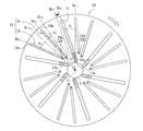
- FIG. 1 is a radial cross-sectional view (transverse cross-sectional view) schematically showing a main part focused on a composite sprocket and a chain of a speed change mechanism according to a first embodiment of the present invention.
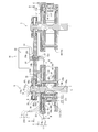
- FIG. 1 is an axial sectional view (longitudinal sectional view) schematically showing a main part focused on a composite sprocket and a chain of a speed change mechanism according to a first embodiment of the present invention. It is a side view paying attention to the fixed disk of the speed change mechanism concerning a first embodiment of the present invention.
- FIG. 3 corresponds to the arrow AA in FIG.
- FIG. 4 corresponds to the arrow BB in FIG.
- FIG. 2 shows a fixed disk and a movable disk for radial movement, such as a pinion sprocket, and a pinion sprocket and a guide rod moved by these in the speed change mechanism according to the first embodiment of the present invention, and the sprocket moving mechanism and the rod moving mechanism are described.
- the radius of the tangent circle increases in the order of (a), (b), (c). Note that (a) shows the smallest radius of the tangent circle, and (c) shows the largest radius.
- FIG. 6 is a cross-sectional view taken along the line CC of FIG. It is radial direction sectional drawing of the speed change mechanism concerning 1st embodiment of this invention.
- FIG. 7 is a sectional view taken along the line DD in FIG. It is a principal part enlarged view which expands and shows the 1st cam groove and 2nd cam groove of the speed change mechanism concerning 1st embodiment of this invention.
- FIG. 8 is a view taken along the line EE in FIG.
- FIG. 2 is a radial cross-sectional view (transverse cross-sectional view) schematically showing an enlarged main part focused on the composite sprocket of the speed change mechanism according to the first embodiment of the present invention.
- FIG. 11 shows a portion corresponding to FIG.
- FIG. 12 shows a portion corresponding to FIG.
- the speed change mechanism of the present embodiment can be used for a vehicle transmission.
- the axial direction is the axis of the rotating shaft in the speed change mechanism or the direction parallel to the axis, and the radial direction and the circumferential direction are determined based on the axis of the rotating shaft.
- the inner side or the outer side with respect to the radial direction means that the distance (radius) from the axis of the rotation axis is the short side or the long side.
- the advance side and the retard side are determined based on the revolution direction in the transmission mechanism.
- the speed change mechanism includes two sets of composite sprockets 5, 5 and a chain 6 wound around these composite sprockets 5, 5.
- a silent chain is illustrated as the chain 6, but a roller chain may be used as the chain 6.
- the white arrow in FIG. 1 shows the revolution direction.
- One of the two sets of composite sprockets 5 and 5 is a pair of composite sprockets 5 (shown on the left in FIG. 1) that rotate integrally with the input-side rotary shaft 1 (input shaft).
- a composite sprocket 5 (shown on the right side in FIG. 1) that rotates integrally with the rotary shaft 1 (output shaft) on the output side. Since these composite sprockets 5 and 5 are configured in the same manner, the configuration will be described by focusing attention on the composite sprocket 5 on the input side.
- the composite sprocket 5 means an apparent large sprocket in which a plurality of pinion sprockets 20 and a plurality of guide rods 29 are formed so as to form the apexes of a polygon (here, an octagon).
- the composite sprocket 5 includes a rotating shaft 1, and a pinion sprocket 20 and a guide rod 29 that are movably supported in the radial direction with respect to the rotating shaft 1.
- six pinion sprockets 20 are arranged at equal intervals along the circumferential direction around the axis C 1 of the rotating shaft 1, and between the pinion sprockets 20, respectively.
- Two guide rods 29 are arranged.
- this speed change mechanism can change the speed ratio continuously, it can be configured as a continuously variable speed change mechanism, but it can also be configured as a multistage stepped speed change mechanism by changing the speed ratio stepwise. it can.
- the outer diameter of the composite sprocket 5 corresponds to the radius of a circle that surrounds all of the plurality of pinion sprockets 20 and is in contact with any of the plurality of pinion sprockets 20 (hereinafter referred to as “pinion contact circle A”). That is, the diameter of the pinion contact circle A is the outer diameter of the composite sprocket.
- the radius of the pinion contact circle A described above also corresponds to the contact radius between the plurality of pinion sprockets 20 and the chain 6, that is, the radius of the pitch circle of the composite sprocket 5. Therefore, in the speed change mechanism, by changing the radius of the pinion contact circle A, the winding radius of the chain 6 is changed, and the speed change ratio is changed.
- FIG. 1 illustrates the pinion tangent circle A that is the smallest on the input side and the largest on the output side.
- the pinion tangent circle A the smallest one is called the minimum pinion tangent circle A 1
- the largest one is called the maximum pinion tangent circle A 2 .
- a pinion contact circle A When attention is not paid to the size or the length, it is simply called a pinion contact circle A.
- the composite sprocket 5 includes a relative rotational drive mechanism 30 that rotationally drives the movable disk 19 relative to the fixed disk 10, and a sprocket moving mechanism 40A that moves the plurality of pinion sprockets 20.
- a rod moving mechanism 40B that moves the plurality of guide rods 29 is provided. Details of these will be described later.
- the composite sprocket 5 of the speed change mechanism will be described.
- a fixed disk 10 that rotates integrally with the rotary shaft 1 a movable disk 19 that is provided so as to be rotatable relative to the fixed disk 10
- the first rotating part 15 that rotates integrally, the second rotating part 16 that rotates integrally with the movable disk 19, the pinion sprocket 20 that meshes with the chain 6, and the guide rod 29 that guides (guides) the chain 6 will be described in this order.
- the relative rotation drive mechanism 30, the sprocket moving mechanism 40A, and the rod moving mechanism 40B will be described in this order.
- the fixed disk 10, the movable disk 19, the first rotating part 15, and the second rotating part 16 are disposed concentrically with the axis C 1 of the rotating shaft 1, and the radial direction of the disks 10, 19 is that of the rotating shaft 1. It coincides with the radial direction.
- a fixed disk 10 and a movable disk 19 are provided adjacent to each other on both axial ends of the rotating shaft 1 (upper end side and lower end side in FIG. 2), A pinion sprocket 20 and a guide rod 29 and a chain 6 wound around these are arranged at an intermediate portion in the axial direction of the rotary shaft 1.
- the movable disk 19 is disposed on the inner side in the axial direction, that is, on the side closer to the pinion sprocket 20, the guide rod 29, and the chain 6.
- FIG. 2 schematically shows the pinion sprocket 20 and the guide rod 29 and a relative rotation drive mechanism 30 described later in the same cross section for easy understanding.
- the input-side composite sprocket 5 and the output are shown in FIG. An interval is provided between the side composite sprocket 5.
- the fixed disk 10 and the movable disk 19 are provided in pairs at both ends in the axial direction of the plurality of pinion sprockets 20 and the plurality of guide rods 29.
- the fixed disk 10 and the movable disk 19 are provided on one side. Focusing on the movable disk 19, its configuration will be described.
- the fixed disk 10 is formed integrally with the rotating shaft 1 or is coupled so as to rotate together with the rotating shaft 1.
- the fixed disk 10 includes a plurality of fixed radial grooves 11 for sprockets (corresponding to only one place) provided for each of the plurality of pinion sprockets 20 and a plurality of guide rods 29.
- the white arrow in FIG. 3 shows the revolution direction.
- the fixed radial groove 11 for sprocket is a groove for guiding the corresponding pinion sprocket 20. That is, the sprocket fixed radial grooves 11 are formed along the radial movement path of the corresponding pinion sprocket 20.
- Each of the fixed radial grooves 11 for the sprocket is configured in the same manner except that the arrangement locations are different. Therefore, a description will be given focusing on one fixed radial groove 11 for sprockets.
- a first support portion 216 of the pinion sprocket 20 is inserted into the fixed radial groove 11 for the sprocket.
- the fixed radial grooves 11 for the sprocket are provided so as to be inclined toward the retard side with respect to the first radial direction Dr 1 in the fixed disk 10. That is, the sprocket fixed radial groove 11 is provided so as to shift toward the retard side with respect to the first radial direction Dr1 as it goes toward the outer periphery (outside in the radial direction).
- the “first radial direction D r1 ” means a radial direction passing through the inner peripheral end portion 11a of the fixed radial groove 11 for sprockets. Accordingly, the extending direction D S1 of the fixed radial groove 11 for the sprocket is inclined toward the retard side at the first inclination angle ⁇ 1 with respect to the first radial direction Dr 1 .
- the fixed radial grooves 11 for sprockets are formed linearly. Therefore, a second radial D r2 parallel to the direction D S1 of extension of the sprocket fixing radial grooves 11 are present on the retard side of the sprocket fixing radial grooves 11. Conversely, when is a second radial D r2 proceeds parallel movement to the advance side as indicated by the black arrows (shift), it coincides with the direction D S1 of extension of the sprocket fixing radial grooves 11.
- the second radial D r2 refers to the direction passing through the axis C 1 of the rotary shaft 1.
- the rod support shaft 29a of the guide rod 29 is inserted into each of the fixed radial grooves 12 for the rod.
- the rod fixed radial grooves 12 are grooves for guiding the corresponding guide rods 29. That is, the fixed radial groove 12 for a rod is formed along the radial movement path of the corresponding guide rod 29.
- the fixed radial grooves 12 for rods are roughly classified into two types: fixed radial grooves 13 for the first rod and fixed radial grooves 14 for the second rod (both are provided with a reference numeral only at one location).
- the inner peripheral end 13 a of the first rod fixed radial groove 13 is farther from the axis C 1 of the rotary shaft 1 than the inner peripheral end 14 a of the second rod fixed radial groove 14. That is, the inner peripheral end portion 13 a of the first rod fixed radial groove 13 is positioned more radially outward than the inner peripheral end portion 14 a of the second rod fixed radial groove 14. Meanwhile, each of the outer peripheral edge 13b and the outer peripheral end portion 14b of the second rod fixed radial grooves 14 of the first rod fixed radial grooves 13, the distance to the axis C 1 of the rotary shaft 1 are equal.
- the fixed radial groove 12 for a rod is formed in a straight line, and shifts toward the retard side with respect to the radial direction as it goes radially outward. It is provided as follows. More specifically, the extending direction D S2 of the first rod fixed radial groove 13 is inclined to the retard side at the second inclination angle ⁇ 2 with respect to the third radial direction Dr3 .
- the “third radial direction D r3 ” means a radial direction passing through the inner peripheral end portion 13 a of the first rod fixed radial groove 13.
- the extending direction D S3 of the second rod fixed radial groove 14 is inclined toward the retard side at the third inclination angle ⁇ 3 with respect to the fourth radial direction Dr 4.
- the “fourth radial direction D r4 ” means a radial direction passing through the inner peripheral end portion 14 a of the fixed radial groove 14 for the second rod.
- the second inclination angle ⁇ 2 applied to the first rod fixed radial groove 13 is larger than the third inclination angle ⁇ 3 applied to the second rod fixed radial groove 14. Therefore, the fixed radial groove 14 for the second rod is formed along the radial direction more than the fixed radial groove 13 for the first rod.
- first rod fixed radial groove 13 and a second rod fixed radial groove 14 are formed between the sprocket fixed radial grooves 11 in the circumferential direction.
- Each of the fixed radial grooves 13 for the first rod is configured similarly except that the arrangement location is different.
- each of the fixed radial grooves 14 for the second rod is configured similarly except that the arrangement location is different.
- the fixed radial grooves 13 and 14 for rods are referred to as fixed radial grooves 12 for rods when not particularly distinguished.
- Each groove width of the fixing radial grooves 11 and 12 has a groove width corresponding to the outer diameter of the member to be inserted. Specifically, the groove width is set to be slightly larger than the outer diameter of the member to be inserted. Therefore, the inserted member can move along the fixed radial grooves 11 and 12 smoothly. Details of the support member 216 and the support shaft 29a, which are the insertion members, will be described later.
- the movable disk 19 is provided on each of one side and the other side with the pinion sprocket 20 and the guide rod 29 interposed therebetween. These movable disks 19 are connected to each other by a connecting shaft 19A.
- connecting shafts 19 ⁇ / b> A reference numerals are given only at one place
- the movable disk 19 on one side and the movable disk 19 on the other side rotate together.
- the movable disk 19 (shown by a broken line in FIG. 5) includes a plurality of movable radial grooves 19a and 19b that intersect with the fixed radial grooves 11 and 12 in the axial direction. (In each case, only one place is given a reference numeral and is shown by a broken line in FIG. 5).
- the outer shape of the movable disk 19 is circular and overlaps with the outer shape (circular shape) of the fixed disk 10 when viewed in the axial direction, but for convenience, FIG. .
- the white arrow in FIG. 4 shows the revolution direction.
- Each of the sprocket movable radial grooves 19a intersects the corresponding sprocket fixed radial groove 11 in the axial direction.
- the second support portion 217 of the pinion sprocket 20 is inserted into the movable radial groove 19a for the sprocket.
- the movable radial groove for sprocket 19a is inclined toward the retard side with respect to the radial direction, and is provided in a curved shape.
- the rod support shaft 29a of the guide rod 29 is inserted into the movable radial groove 19b for the rod.
- the rod movable radial groove 19b intersects with the corresponding rod fixed radial groove 12 in the axial direction.
- the rod movable radial groove 19b is axially viewed with each of the first rod movable radial groove 191 and the second rod fixed radial groove 14 and intersects with each of the first rod fixed radial grooves 13 in the axial direction. And the second rod movable radial groove 192 intersecting with each other.
- the inner peripheral end of the first rod movable radial groove 191 is relative to the axis C 1 of the rotary shaft 1 more than the inner peripheral end of the second rod movable radial groove 192. The distance is far. On the other hand, the distance between the outer peripheral end of the first rod movable radial groove 191 and the outer peripheral end of the second rod movable radial groove 192 is equal to the axis C 1 of the rotary shaft 1.
- Each groove width of the movable radial grooves 19a, 19b has a groove width corresponding to the outer diameter of the member to be inserted. Specifically, the groove width is set to be slightly larger than the outer diameter of the member to be inserted. Therefore, the inserted member can smoothly move along the movable radial grooves 19a and 19b.
- the details of the second support portion 217 and the rod support shaft 29a, which are members to be inserted, will be described later.
- the first rotating portion 15 is a portion that rotates integrally with the fixed disk 10, that is, a portion that rotates integrally with the rotating shaft 1.
- the first rotating portion 15 is provided on a part of the rotating shaft 1.
- the first rotating portion 15 is disposed on the outer side in the axial direction than the fixed disk 10 and the movable disk 19.
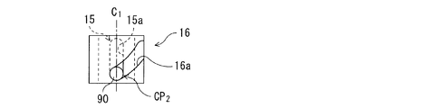
- the first rotating portion 15 is provided with a first cam groove 15a.
- the first cam groove 15 a is provided so as to be recessed along the axial direction of the rotary shaft 1.
- the first cam groove 15 a is formed in parallel with the axis C 1 of the rotary shaft 1.
- FIG. 7 illustrates an example in which the first cam groove 15a (only one place is provided with a reference numeral) is provided at three places at intervals in the circumferential direction. May be set according to the surrounding configuration, required specifications, and the like, and various shapes and numbers can be employed.
- the white arrow in FIG. 7 shows the revolution direction.
- the connecting portion 17 is disposed so as to rotate integrally with the movable disc 19 and the second rotating portion 16 and cover the fixed disc 10.
- the connection portion 17 includes an axial connection portion 17 a that covers the outer periphery of the fixed disk 10 and a radial connection portion 17 b that covers the outer side of the fixed disk 10 in the axial direction.
- the axial direction connection part 17 a connects the axial component separations, and connects the radial separations. It is the radial direction connection part 17b.
- Axial connection portion 17a has a cylindrical shape extending in the axial direction together provided the axis C 1 and concentric rotary shaft 1. As shown in FIG. 2, the axial direction connecting portion 17a is connected to the outer peripheral end portion (outer peripheral portion) 19t of the movable disk 19, and the axially outer side is connected to a radial connecting portion 17b described below. Has been.
- the radial direction connecting portion 17 b has a radially outer side connected to the axial direction connecting portion 17 a and a radially inner side connected to the second rotating portion 16.
- the radial connection portion 17b is formed in a lightening shape by lightening portion 17c which will be described from the disc which extends radially with provided the axis C 1 and concentric rotary shaft 1.
- the radial connection portion 17b is provided with a lightening portion 17c.
- fan-shaped thinned portions 17c provided at three locations are provided at equal intervals with the radial connection portion 17b interposed therebetween.
- the shape and number of the thinned portions 17c may be set according to the surrounding configuration, required specifications, and the like, and various shapes and numbers can be employed.
- the thinned portion 17c may be omitted, and the radial connection portion 17b may be formed in a disk shape.
- the second rotating portion 16 is connected to the outer peripheral end portion 19t of the movable disk 19 via the connecting portions 17a and 17b and is provided so as to cover the outer periphery near the first rotating portion 15. It is formed in the heart C 1 concentric cylindrical.
- the second rotating portion 16 is provided with a second cam groove 16a.
- the second cam groove 16a is adjacent to the outer periphery of the first cam groove 15a and is provided along the rotary shaft 1 and intersects the first cam groove 15a in the radial direction.
- the second cam groove 16a is provided so as to intersect the axial direction.
- FIG. 7 illustrates a case where the second cam groove 16a (the reference numeral is attached only at one place) is provided at three places. It is set according to the formation location and number of formation of 15a.
- pinion sprocket 20 and guide rod 29 only revolve and do not rotate.
- “spinning” means that each of the pinion sprocket 20 and the guide rod 29 rotates around its own axis.
- the pinion sprockets 20 are arranged at equal intervals along the circumferential direction around the axis C 1 of the rotary shaft 1. Specifically, a first pinion sprocket 210, a second pinion sprocket 220, a third pinion sprocket 230, a fourth pinion sprocket 240, a fifth pinion sprocket 250, and a sixth pinion sprocket 260 are arranged. These pinion sprockets 210, 220, 230, 240, 250, 260 are configured similarly except that their arrangement locations are different.
- the pinion sprockets 210, 220, 230, 240, 250, and 260 are collectively referred to simply as the pinion sprocket 20. Further, the configuration will be described by paying attention to the first pinion sprocket 210.
- FIG. 2 shows an example in which a row of pinion sprockets 210 is provided in the axial direction. However, the number of rows of pinion sprockets 210 can be changed according to the magnitude of the transmission torque of the speed change mechanism, for example.
- the first pinion sprocket 210 has a main body 211 and a support member 215.
- the main body part 211 has a tooth part 212 and a base part 213.
- the tooth portion 212 is provided on the radially outer side of the base portion 213 and meshes with the chain 6.
- the tooth portion 212 has a plurality of (here, four) teeth. That is, the first pinion sprocket 210 is formed in a sector gear (fan gear) shape with the tooth portion 212 provided not on the entire circumference but on a part thereof.
- the tooth portion 212 is provided along the circumference of the minimum pinion tangent circle A 1 . Specifically, in a state where the minimum pinion Se'en A 1, the tip of each tooth in the tooth portion 212 (outer peripheral end) is in contact with the minimum pinion Se'en A 1. In addition, the white arrow in FIG. 9 shows the revolution direction.
- the tooth part 212 is roughly divided into a first tooth part 22a and a second tooth part 22b.
- the first tooth portion 22a is arranged so that at least one tooth (one tooth) exists within the groove width of the fixed radial groove 11 for sprockets. That is, at least one tooth of the first tooth portion 22a overlaps with the groove of the sprocket fixed radial groove 11 when viewed in the axial direction.
- the two teeth on the advance side in the tooth part 212 correspond to the first tooth part 22a.
- the second tooth portion 22b is a portion extending from the first tooth portion 22a to the retard side.
- the second tooth portion 22b, to the first tooth portion 22a, is extended to the area of the parallel to the direction D S1 of extension of the sprocket fixing radial grooves 11 and second radial D r2. That is, the second tooth portion 22b is more than the distance between the direction D S1 second parallel thereto and in the radial direction D r2 of extension of the sprocket fixing radial grooves 11, offset with respect to first tooth portion 22a extending It is installed.
- the base portion 213 has a shape in which the radially inner side of the second tooth portion 22b is cut out. In other words, a space S is formed on the retard side of the base portion 213 and on the radially inner side of the second tooth portion 22b.
- the base 213 is supported by a support member 215 described below.
- the support member 215 includes a first support portion 216, a second support portion 217, and a third support portion 218 in order from the axial end portion, and the first pinion sprocket. 210 are provided on both sides of 210. And the 1st support part 216 and the 2nd support part 217 are couple
- the first support portion 216 is inserted into the sprocket fixed radial groove 11 as described above. That is, the axial position of the first support portion 216 and the axial position of the fixed disk 10 are the same.
- the first support portion 216 is formed in a corresponding shape so as to contact the sprocket fixed radial groove 11 over a predetermined length in the radial direction. Therefore, when a rotational force that rotates the first pinion sprocket 210 is applied, the first support portion 216 transmits the rotational force to the sprocket fixed radial groove 11 and the reaction (reaction force) of this rotational force. ) To prevent the first pinion sprocket 210 from rotating.
- the first support portion 216 is formed in a shape having a detent function in the fixed radial groove 11 for sprockets.
- the “predetermined length” applied to the first support portion 216 means a length that can secure a drag force of the rotational force that causes the first pinion sprocket 210 to rotate.
- the first support portion 216 has a longitudinal direction along the radial direction, and is formed in a rectangular parallelepiped key shape, for example.
- the fixed radial groove 11 for sprockets is also a key groove.
- the reaction force of the drive torque acts on the first support portion 216 and the inner wall of the sprocket fixed radial groove 11. Further, if the bearings are attached to the side wall of the first support portion 216 in contact with the inner wall of the fixed radial groove 11 for the sprocket, particularly the four corners of the first support portion 216, the first support member 216 can be smoothly moved in the radial direction. can do.
- the second support portion 217 is inserted into the sprocket movable radial groove 19a as described above. That is, the axial position of the second support portion 217 and the axial position of the movable disk 19 are the same.
- the 2nd support part 217 is formed in the column shape.
- the third support part 218 is coupled to the base part 213.
- the third support portion 218 supports the first pinion sprocket 210 so as not to be relatively rotatable.
- the third support portion 218 is illustrated as being formed in a columnar shape having a smaller diameter than the second support portion 217.
- the fixed radial groove 11 'for the sprocket is provided in a curved shape like the above-described movable radial groove 19a for the sprocket, and this fixed radial groove 11' for the sprocket is provided.
- the shape of the first support portion 216 ′ inserted in is also provided in a corresponding shape.
- the first support portion 216 ′ one formed in a cylindrical shape like the second support portion 217 can be used, and the longitudinal direction is formed along the fixed radial groove 11 ′ for the sprocket. May be used.
- the sprocket movable radial groove 19'a is linearly provided like the above-described sprocket fixed radial groove 11 and is inserted into the sprocket movable radial groove 19'a.
- the shape of the two support portions 217 ' is also provided in a corresponding shape.
- the second support portion 217 ' is formed in a rectangular parallelepiped shape (key shape) having a longitudinal direction in the radial direction.
- the driving torque and the reaction force act on the movable radial groove 19′a for the sprocket and the second support portion 217 ′.
- the plurality of guide rods 29 are arranged so as to reduce the variation in the distance between the chain 6 and the axis C 1 of the rotation shaft 1 (the variation in the winding radius of the chain 6), that is, the rotation shaft. This is for guiding the chain 6 so that the trajectory of the one chain 6 is as close to the circular trajectory as possible.
- These guide rods 29 are provided so as to be movable in the radial direction, and the chain 6 is wound around to form a polygonal apex. Further, unlike the pinion sprocket 20, the guide rod 29 does not mesh with the chain 6 and does not contribute to power transmission.
- Such guide rods 29 are roughly classified into two types: a first guide rod 291 (a reference is given to only one place) and a second guide rod 292 (both have a reference to only one place).
- Each of the first guide rods 291 has the same configuration except that the arrangement location is different. Moreover, each of the 2nd guide rod 292 is comprised similarly except the point from which an arrangement
- the guide rod 29 is formed by extrapolating a cylindrical guide member 29b on the outer periphery of the rod support shaft 29a, supported by the rod support shaft 29a, and chained on the outer peripheral surface of the guide member 29b.
- Guide 6 The rod support shaft 29a protrudes from the guide member 29b in the axial direction at both end portions 29A in the axial direction of the guide rod 29 (only one end portion in the axial direction is given a reference numeral).
- the protruding rod support shaft 29 a is supported by the fixed disk 10 and the movable disk 19. That is, the guide rod 29 has a rod support shaft 29a and a cylindrical guide member 29b partially covered at an axial position in contact with the chain 6 on the rod support shaft 29a.
- the first guide rod 291 always guides the chain 6 regardless of the radial position (the radius of the pinion contact circle A).
- the second guide rod 292 does not guide the chain 6 in the state where it is at or near the minimum pinion contact circle A 1, but in the state where it reaches the maximum pinion contact circle A 2 together with the first guide rod 291 Guide 6 That is, any of the guide rods 29 guides the chain 6 in the state where the maximum pinion contact circle A 2 is reached.
- the second guide rod 292 in the state of forming the minimum pinion tangent circle A 1 is the periphery of the space S formed on the retard side of the base 213 and radially inward of the second tooth portion 22b. Located in. Specifically, the second guide rod 292 is located slightly behind the space S. Note that the second guide rod 292 that forms the minimum pinion tangent circle A 1 may be positioned in the space S on the radially inner side with respect to the second tooth portion 22b. In this case, the notch amount on the retard side of the base 213 is increased, and the radial grooves 14 and 192 on the second guide rod 292 are formed in corresponding shapes.
- the shapes of the fixed radial grooves for rods 13 and 14 and the movable radial grooves for rods 191 and 192 are set so that the radial positions of the guide rods 291 and 292 are the positions described above.
- the first guide rods 291 and the second guide rods 292 are alternately arranged along the circumferential direction. Specifically, the second guide rod 292 and the first guide rod 291 are arranged in this order on the retard side of the first pinion sprocket 210.
- the guide rods 29 are not limited to the arrangement in which two guide rods 29 are provided between the pinion sprockets 20, and the total number is not limited to twelve.
- the greater the number of the first guide rods 291 the more likely the radius of the minimum pinion contact circle A 1 is increased, and in addition, there is a risk of increasing manufacturing costs and weight due to an increase in parts. In consideration of these, it is preferable to set the number of guide rods 29.
- the relative rotation drive mechanism 30 is a mechanism for mechanically interlocking the composite sprockets 5 and 5.
- the relative rotation drive mechanism 30 includes the first cam groove 15a and the first cam groove 15a.
- a cam roller 90 disposed at a first intersection CP 1 where the second cam groove 16a intersects, a speed change fork 35 for moving the cam roller 90 in the axial direction, and a speed change fork 35 for moving in the axial direction.
- An axial movement mechanism 31 is provided.
- the cam roller 90, the speed change fork 35, and the axial movement mechanism 31 will be described in this order.
- the cam roller 90 is formed in a cylindrical shape.
- This cam roller 90 has an axial center along a direction orthogonal to the axial center C 1 of the rotary shaft 1, and a first intersection CP 1 (both of which the first cam groove 15 a and the second cam groove 16 a intersect each other). It is inserted through only one place. For this reason, the cam roller 90 rotates around the axis C 1 of the rotating shaft 1 in conjunction with the rotation of the rotating shaft 1.
- a bearing 91a is externally provided at a location corresponding to the first cam groove 15a, and similarly, a bearing 91b is externally fitted at a location corresponding to the second cam groove 16a.
- One end portion 90a of the cam roller 90 is provided to be protruded from the first intersection CP 1 radially outward.
- the cam roller 90 is appropriately secured so as not to drop out of the cam grooves 15a and 16a.
- Examples of the retaining process include providing a head at the other end of the cam roller 90 and adding a retaining pin so that the cam roller 90 can move in the axial direction but not in the radial direction. It is done.
- the transmission fork 35 is provided across the two sets of composite sprockets 5, 5.
- the speed change fork 35 is formed in a glasses shape when viewed in the axial direction.
- the speed change fork 35 includes an annular cam roller support portion 35a (referenced only on one side) provided corresponding to each of the composite sprockets 5, 5, and a bridge portion 35b for connecting the cam roller support portions 35a.
- Have The first rotating portion 15 and the second rotating portion 16 are disposed on the radially inner side of the cam roller support portion 35a.
- the speed change fork 35 is a plate-like member parallel to the disks 10 and 19, and is juxtaposed on the outer side in the axial direction with respect to the disks 10 and 19 when the chain 6 is used as a reference.
- the groove part 35c is recessedly provided in the cam roller support part 35a over the perimeter of radial inside.
- the groove portion 35 c has a depth corresponding to the protruding length of the cam roller 90 and accommodates one end portion 90 a of the cam roller 90. That is, the groove part 35 c has an annular space whose radial direction is the protruding length of the cam roller 90.
- the groove 35c is provided with a rolling element 35d (a reference numeral is given only at one place) that can be in rolling contact with the cam roller 90.
- the rolling element 35d is cam roller 90 is provided to prevent the rotation around the axis when the cam roller 90 that rotates about the axis C 1 of the rotary shaft 1 is brought into contact with the side wall of the groove 35c . That is, the rolling element 35d is disposed on the cam roller support portion 35a that forms the side wall of the groove portion 35c.
- a plurality of rolling elements 35d are arranged over the entire circumference of the groove 35c.
- a needle bearing is illustrated as the rolling element 35d, it may replace with this and may use a ball bearing.
- the axial movement mechanism 31 supports the motor 32, the motion conversion mechanism 33 that switches the rotational motion of the output shaft 32 a of the motor 32 to linear motion, and the speed change fork 35 in order to move the speed change fork 35 in the axial direction.
- a fork support portion 34 that is linearly moved by the motion conversion mechanism 33 is provided.
- the motor 32 a stepping motor can be used.
- the axial direction movement mechanism 31 will be described in the order of the fork support portion 34 and the motion conversion mechanism 33.
- the fork support portion 34 is formed in a cylindrical shape having a cylindrical shaft concentric with the output shaft 32 a of the motor 32. An output shaft 32 a of the motor 32 is inserted into the fork support portion 34.
- the fork support portion 34 has a female screw portion 34a that is screwed into an inner periphery and is engaged with a male screw portion 32b formed on the output shaft 32a of the motor 32, and is engaged with the bridge portion 35b of the speed change fork 35 on the outer periphery.
- a mating fork groove 34b is recessed.
- the fork groove 34b is formed to have a width (axial length) corresponding to the thickness (axial length) of the bridge portion 35b of the transmission fork 35.
- An intermediate portion of the bridge portion 35b (between the two composite sprockets 5 and 5) is fitted into the fork groove 34b, and the fork support portion 34 and the bridge portion 35b of the transmission fork 35 are integrally coupled.
- the motion conversion mechanism 33 includes a male screw portion 32b of the output shaft 32a and a female screw portion 34a of the fork support portion 34.
- the fork support portion 34 in which the female screw portion 34a is formed is moved in the axial direction by screwing the male screw portion 32b and the female screw portion 34a. That is, the axial direction moving mechanism 31 converts the rotational motion of the motor 31 into a linear motion by the motion converting mechanism 33 and causes the fork support portion 34 to linearly move in the axial direction by this linear motion.
- the relative rotation drive mechanism 30 including the transmission fork 35 and the axial movement mechanism 31 is provided so as to be shifted in the axial direction from the pinion sprockets 21, 22, and 23.
- the first intersection CP 1 When the cam roller 90 of the first cam groove 15a and the second cam groove 16a is disposed on the first intersection CP 1 crossing is moved in the axial direction, the first intersection CP 1 also moves in the axial direction. Since the first rotating portion 15 first cam groove 15a is provided to rotate integrally with the rotary shaft 1 and the fixed disk 10, when the first intersection CP 1 is moved in the axial direction, first with respect to the first rotating portion 15 The second rotating portion 16 provided with the two cam grooves 16a is relatively rotated. Since the second rotating unit 16 rotates integrally with the movable disk 19 and the first rotating unit 10 rotates integrally with the fixed disk 10, the second rotating unit 16 is fixed when the second rotating unit 16 is rotated relative to the first rotating unit 15. The movable disk 19 is rotated relative to the disk 10.
- the sprocket moving mechanism 40A has the pinion sprocket 20 as a moving object
- the rod moving mechanism 40B has a plurality of guide rods 29 as moving objects.
- the rod moving mechanism 40B serves as both the first rod moving mechanism 401 whose target is the first guide rod 291 and the first rod moving mechanism 402 whose target is the second guide rod 292.
- These moving mechanisms 40A, 40B (401, 402) move each moving object in synchronization with the radial direction.
- the sprocket moving mechanism 40A includes a fixed disk 10, a movable disk 19, and a relative rotation driving mechanism 30 (see FIGS. 2 and 7).
- the rod moving mechanism 40 ⁇ / b> B includes the fixed disk 10, the movable disk 19, and the relative rotation drive mechanism 30.
- the configuration of each of the moving mechanisms 40A and 40B is the same except for the respective moving targets.
- FIGS. 5 (a) shows the phase with respect to the fixed disk 10 of the movable disk 19 in a state where the minimum pinion Se'en A 1.
- the second intersecting point CP 2 where the sprocket fixed radial groove 11 and the sprocket movable radial groove 19 a intersect is closest to the axis C 1 of the rotating shaft 1.
- a third intersecting point CP 3 where the first rod fixed radial groove 13 and the first rod movable radial groove 191 intersect, a second rod fixed radial groove 14 and a second rod movable radial groove 192 are provided.
- the intersecting fourth intersecting points CP 4 are closest to the axis C 1 of the rotating shaft 1, respectively.
- the fourth intersection point CP 4 is located on the radially inner side than the third intersection point CP 3 . This corresponds to the second guide rod 292 being disposed radially inward of the first guide rod 291 in the state where the minimum pinion tangent circle A 1 is formed.
- the sprocket moving mechanism 40A moves each of the pinion sprockets 20 supported at the second intersection CP 2 in synchronization with the radial direction while maintaining an equal distance from the axis C 1 of the rotating shaft 1.
- the first rod moving mechanism 401 synchronizes the first guide rods 291 supported at the third intersection CP 3 in the radial direction while maintaining an equal distance from the axis C 1 of the rotating shaft 1.
- the second rod moving mechanism 402 is configured so that each of the second guide rods 292 supported at the fourth intersection CP 4 is kept at an equal distance from the axis C 1 of the rotating shaft 1 and is the smallest pinion.
- the tooth part 212 of the pinion sprocket 20 is provided along the circumference of the minimum pinion contact circle A 1 . Therefore, compared with a pinion sprocket having a conventional sprocket gear shape, the number of teeth meshing with the chain 6 can be ensured at the tooth portion 212 of the pinion sprocket 20. More specifically, the tooth portion 212 can be formed larger than a pinion sprocket having a sprocket gear shape. Therefore, the burden on the tooth portion 212 meshing with the chain 6 can be reduced. Therefore, torque can be transmitted reliably.
- the advance angle is particularly advanced with respect to the circumference of the pinion contact circle A.
- the teeth on the side are separated.
- the circumference of the smallest pinion Se'en a 1 is because contact with the circumference of the pinion Se'en a.
- the first tooth portion 22a disposed so that the tooth portion 212 of the pinion sprocket 20 is within the groove width of the fixed radial groove 11 for the sprocket, and the first tooth portion. 22a and a second tooth portion 22b extending from the retard angle side. Therefore, even in a state where the maximum pinion Se'en A 2 is the second tooth portion 22b easily along the circumference forms a maximum pinion Se'en A 2. Therefore, regardless of the size of the pinion contact circle A, the meshing between the second tooth portion 22b and the chain 6 can be stabilized, and the torque can be reliably transmitted.
- the fixed radial grooves 11 and 12 of the fixed disk 10 are provided to be inclined with respect to the radial direction, it is easy to secure an intersecting angle between the fixed radial grooves 11 and 12 and the movable radial grooves 19 a and 19 b of the movable disk 19. Become. Therefore, it is possible to reduce the rotational torque of the movable disk 19 with respect to the fixed disk 10 in relation to the radial movement of the pinion sprocket 20 and the guide rod 29, and the pinion sprocket 20 in the fixed radial grooves 11, 12 and the movable radial grooves 19a, 19b.
- the support members 216 and 217 and the rod support shaft 29a of the guide rod 29 can be prevented from being caught (stick).
- second tooth portion 22b to the first tooth portion 22a, is extended to the area of the parallel to the direction D S1 of extension of the sprocket fixing radial grooves 11 and second radial D r2. Accordingly, the second tooth portion 22b provided at a location where the second radial D r2 intersects the circumference of the pinion Se'en A, along the circumference of the pinion Se'en A regardless of the radius of the pinion Se'en A The second tooth portion 22b can be positioned. Therefore, torque can be transmitted more reliably.
- the fixed radial groove 11 for sprocket is provided so as to shift toward the retard side with respect to the first radial direction Dr1 as it goes toward the outer periphery. Therefore, part of the reaction force of the driving torque (force component), can act radially outwardly of the direction D S1 of extension of the sprocket fixing radial grooves 11. That is, when the driving torque is transmitted, a force that moves the pinion sprocket 20 radially outwards acts, so that the slack of the chain 6 can be suppressed and various mechanisms related to the speed change mechanism can be loosened. .
- the first support portion 216 is formed in a corresponding shape so as to be in contact with the fixed radial groove 11 for sprockets over a predetermined length in the radial direction. Therefore, when a rotational force that rotates the pinion sprocket 20 is applied, the rotation of the pinion sprocket 20 can be prevented by the reaction (resistance force) of the rotational force to the fixed radial groove 11 for the sprocket.
- the guide rod 29 includes a first guide rod 291 that guides the chain 6 and a second guide rod 292 that is positioned radially inward of the first guide rod 291 in a state of forming a minimum pinion contact circle A 1.
- a second guide rod 292 that is positioned radially inward of the first guide rod 291 in a state of forming a minimum pinion contact circle A 1.
- the distances of the first guide rod 291 and the second guide rod 292 with respect to the axis C 1 of the rotary shaft 1 are equal. That is, any of the guide rods 29 guides the chain 6 in the state where the maximum pinion contact circle A 2 is reached. Therefore, the chain 6 can be guided by all of the first guide rod 291 and the second guide rod 292. That is, the number of guide rods 29 that guide the chain 6 can be ensured in the state where the chain 6 wound around the composite sprocket 5 has the maximum pinion contact circle A 2 that is the longest. Therefore, the fluctuation
- the second guide rod 292 in the state of forming the minimum pinion tangent circle A 1 is positioned around the space S formed on the retard side of the base 213 and radially inward of the second tooth portion 22b. Since this space S can be said to be formed by extending the second tooth portion 22b from the first tooth portion 22a, it can be said to be unique to the present speed change mechanism. Using the space S, the second guide rod 292 can be accommodated (stored). That is, in this speed change mechanism, the space S that can be a so-called dead space can be effectively used as the accommodation space for the second guide rod 292 in the state of forming the minimum pinion contact circle A 1 . If the second guide rod 292 is positioned in the space S in a state where the minimum pinion tangent circle A 1 is formed, the space S can be used more effectively as the accommodation space for the second guide rod 292.
- the speed change mechanism of the present embodiment mainly differs in the configuration of the pinion sprocket itself, the guide rod accommodation state, and the radial movement path. Except for the points described in the second embodiment, the configuration is the same as that of the first embodiment. About these structures, the same code
- the speed change mechanism of the present embodiment will be described focusing on the differences from the first embodiment.
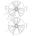
- the transmission mechanism includes two sets of composite sprockets 5 'and 5' and a chain 6 'wound around these composite sprockets 5' and 5 '.
- the white arrow in FIG. 11 shows the revolution direction.
- the composite sprocket 5 ' has a rotating shaft 1', and a pinion sprocket 20 'and a guide rod 29' supported so as to be movable in the radial direction with respect to the rotating shaft 1 '.
- These pinions sprocket 20 'and the guide rods 29' revolves the axis C 1 around the rotation axis 1 '.
- an apparent large sprocket formed by the pinion sprocket 20 'and the guide rod 29' so as to form the apex of a twenty-one-sided shape forms a composite sprocket 5 '.
- the transmission ratio is changed in the present transmission mechanism by expanding / contracting the outer diameter of the composite sprocket 5 ′, that is, the pinion contact circle A ′.
- the composite sprocket 5 ′ includes, as basic components, the first rotating portion 15, the second rotating portion 16 and the relative rotation driving mechanism 30 similar to those described in the first embodiment, the pinion sprocket 20 ′, and a guide.
- a rod 29 ', a fixed disk 10', a movable disk 19 ', and a rotating shaft 1' are provided.
- the composite sprocket 5 ' is a mechanism for operating basic components, in addition to the relative rotation drive mechanism 30 similar to that described above in the first embodiment, the sprocket moving mechanism 40A', the rod moving mechanism 40B '.
- the mechanical rotation drive mechanism 50 is provided.
- These pinion sprockets 20 ' have one pinion sprocket (hereinafter referred to as "fixed pinion sprocket") 21' that does not rotate and the rotation phase of revolution on the advance side and retard side on the basis of this fixed pinion sprocket 21 '. It is composed of two rotation pinion sprockets 22 'and 23' which are arranged and can rotate.
- the one on the advance side with reference to the fixed pinion sprocket 21 ' is referred to as the first rotation pinion sprocket (advanced side rotation pinion sprocket) 22', and the retarded side Is called a second rotation pinion sprocket (retarding side rotation pinion sprocket) 23 '.
- the fixed pinion sprocket 21 'does not rotate, a tooth portion may be partially formed only in a region engaging with the chain 6'. That is, the tooth portion may not be formed on the radially inner side of the fixed pinion sprocket 21 ′.
- Each of the pinion sprockets 21 ', 22', 23 ' is coupled to a support shaft (pinion sprocket shaft) 21'a, 22'a, 23'a provided at the center thereof. That is, rotation pinion sprocket 22 ', 23' each, support shafts 22'a, rotates the axis C 2, C 3 around 23'a.
- the shaft centers C 2 , C 3 , C 4 of the support shafts 21′a, 22′a, 23′a and the shaft center C 1 of the rotating shaft 1 ′ are all parallel to each other.
- first rotation pinion sprocket 22 'and the second rotation pinion sprocket 23' are configured in the same manner except for the arrangement location and the rotation direction, attention is paid to the first rotation pinion sprocket 22 '. I will explain. In the following description, when the fixed pinion sprocket 21 ′, the first rotation pinion sprocket 22 ′ and the second rotation pinion sprocket 23 ′ are used without distinction, they are simply referred to as the pinion sprocket 20 ′, and similarly, the support shafts 21′a, 22 ′. When a and 23'a are also used without distinction, they are called support shafts 20'a.
- the pinion sprocket 20 ′ includes three rows of gears 20′g in the axial direction (reference numerals are given to only one portion), and corresponds to the gears of these rows.
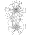
- FIG. 12 is a schematic view for ease of understanding, and shows the first rotation pinion sprocket 22 ′, the guide rod 29 ′, and the relative rotation drive mechanism 30 in the same cross section, and the composite sprocket on the input side. An interval is provided between 5 'and the composite sprocket 5' on the output side.
- first guide rod 291' (signs are given only at one place) and a second guide rod 292 '(both are given signs only at one place).
- first guide rods 291 ′ are configured similarly except that the arrangement location is different.
- second guide rods 292 ′ is configured in the same manner except that the arrangement locations are different.
- these guide rods 291 ′ and 292 ′ will be referred to as guide rods 29 ′ unless otherwise distinguished.
- six guide rods 29 ' are arranged between the pinion sprockets 20'. These six guide rods 29 'are composed of four first guide rods 291' and two second guide rods 292 '. Further, when the two first guide rods 291 ′ and the one second guide rod 292 ′ are regarded as one set, they are adjacent to each other in the circumferential direction, and the first guide rod 291 ′ and the second guide rod 291 ′ are adjacent to each other. Guide rods 292 are alternately arranged along the circumferential direction.
- the first guide rod 291 ′ always guides the chain 6 ′ regardless of the radial position (the radius of the pinion contact circle A).
- the second guide rod 292 ′ guides the chain 6 ′ when the radius of the pinion contact circle A ′ is equal to or larger than a predetermined diameter. Therefore, any of the guide rods 29 'guides the chain 6' in a state where the maximum pinion contact circle A 2 'is reached.
- the predetermined diameter here is a diameter larger than the minimum pinion tangent circle A 1 ′ and smaller than the maximum pinion tangent circle A 2 ′, and when the radius of the pinion tangent circle A is a predetermined diameter, the first guide rod The size is set such that 291 ′ and the second guide rod 292 ′ do not interfere (contact).
- the second guide rod 292 ′ is equal in distance to the axis C 1 of the rotating shaft 1 to that of the first guide rod 291 ′, and the chain 6 ′ is invite.
- the second guide rod 292 ′ is positioned radially inward from the first guide rod 291 ′ as the radius of the pinion contact circle A ′ becomes smaller than a predetermined diameter. Therefore, in the state where the minimum pinion tangent circle A 1 ′ is formed, the second guide rod 292 ′ is located on the innermost radial direction with respect to the first guide rod 291 ′.
- the second guide rod 292 ′ comes into contact with the outer peripheral surface 1 ′ a of the rotating shaft 1 ′, and the first guide rod 291 ′ is brought into contact with the second guide rod 292 ′.
- the second guide rod 292 ′ is accommodated (stored) on the axis C 1 side of the rotating shaft 1 ′ with respect to the first guide rod 291 ′.
- the shape of radial grooves formed in the disks 10 'and 19' described below is set so that the radial positions of the guide rods 291 'and 292' are the positions described above.
- the fixed disk 10 ′ includes a fixed radial groove 111 for a sprocket provided corresponding to each of the plurality of pinion sprockets 20 ′ and a fixed radial groove 112 for a rod provided corresponding to each of the plurality of guide rods 29 ′.
- Two types of fixed radial grooves are formed.
- a support shaft 20'a of the pinion sprocket 20 ' is inserted in the fixed radial groove 111 for the sprocket, and a rod support shaft 29'a of the guide rod 29' is inserted in the fixed radial groove 112 for the rod.
- each of the fixed radial groove 111 for the sprocket and the fixed radial groove 112 for the rod extends radially, and is provided to be inclined toward the retard side with respect to the radial direction.
- the fixed radial groove 112 for the rod is a first fixed radial groove for the rod in which the rod support shaft 29a 'of the first guide rod 291' is inserted, and the rod support shaft 29'a of the second guide rod 292 'is inserted.
- a plurality of movable radial grooves for sprockets 119 intersecting with each of the fixed radial grooves for sprockets in the axial direction are formed in the movable disk 19 ', and each of the fixed radial grooves for rods 112 is axially formed.
- a plurality of movable radial grooves 129 for rods that intersect with each other are formed.
- each of the movable radial grooves 119 and 129 is provided to be inclined toward the advance side with respect to the radial direction.
- each of the movable radial groove for sprocket 119 and the movable radial groove for rod 129 is provided to be inclined toward the advance side with respect to the radial direction.
- the rod movable radial groove 129 includes the first rod movable radial groove in which the rod support shaft 29 ′ a of the first guide rod 291 ′ is inserted at the intersection of the first rod fixed radial groove and the first rod fixed radial groove. It is roughly divided into a movable radial groove for the second rod into which the rod support shaft 29'a of the second guide rod 292 'is inserted at the intersection with the fixed radial groove for the two rods.
- the radial groove applied to the second guide rod 292 ′ is longer than the radial groove applied to the first guide rod 291 ′.
- the radial groove on the first guide rod 291 ′ includes a position where the radius of the pinion contact circle A ′ forms a predetermined diameter. Outside this position, the inclination of each disk 10 ′, 19 ′ with respect to the radial direction is the first guide. It is formed in the same manner as that of the radial groove on the rod 291 ′, and on the radially inner side of the predetermined diameter, the inclination of each disk 10 ′, 19 ′ with respect to the radial direction of the radial groove on the first guide rod 291 ′ It is smaller than that.
- the shape of each radial groove is set corresponding to the movement locus of the guide rods 291 ′ and 292 ′ described above.
- the rotary shaft 1 ' is formed with a recess 2 in which each pinion sprocket 20' can be accommodated.
- the pinion sprocket 20 ′ is housed most deeply in a state where the minimum pinion tangent circle A 1 ′ is formed. From this state, as the radial position of the pinion sprocket 20 'moves to the outer peripheral side (expanded side), the accommodation degree (accommodation depth) of the pinion sprocket 20' into the recess 2 decreases, and further the radial direction. When the position moves outward, the pinion sprocket 20 ′ is not accommodated in the recess 2.
- the recess 2 is formed by recessing the rotation shaft 1 'in a shape corresponding to the corresponding pinion sprocket 20'.
- the recess 2 has a shape in which a part of a cylinder having a bottom surface or a top surface formed by connecting the tips (outer peripheral ends) of the respective tooth portions of the pinion sprocket 20 ′ is removed from the cylindrical rotation shaft. Is formed. If the tooth portion is partially formed on the fixed pinion sprocket 21 'and the tooth portion is not formed on the radially inner side, the recess 2 is formed in a shape corresponding to the fixed pinion sprocket 21'.
- each of the pinion sprockets 20 ′ comes into contact with each recess 2.
- the pinion sprocket 20 ′ is accommodated in the recess 2 so as to bite into the rotating shaft 1 ′.
- the second guide rod 292 ′ is in contact with the outer peripheral surface 1 a of the rotating shaft 1 positioned between the recesses 2 as described above.
- the sprocket moving mechanism 40A ′ is configured in the same manner as the sprocket moving mechanism 40A of the first embodiment, except that the moving object is the pinion sprocket 20 ′ unlike the pinion sprocket 20 of the first embodiment. That is, the sprocket moving mechanism 40A ′ is composed of the fixed disk 10 ′, the movable disk 19 ′, and the relative rotation drive mechanism 30.
- the rod moving mechanism 40B ′ is configured in the same manner as the rod moving mechanism 40B of the first embodiment, except that the moving object is the guide rod 29 ′ unlike the guide rod 29 of the first embodiment. . That is, the rod moving mechanism 40B ′ is composed of the fixed disk 10 ′, the movable disk 19 ′, and the relative rotation drive mechanism 30.
- the rod moving mechanism 40B ′ serves as both a first rod moving mechanism that moves the first guide rod 291 ′ and a second rod moving mechanism that moves the second guide rod 292 ′. These moving mechanisms 40A 'and 40B' move each moving object in synchronization with the radial direction.
- the second rod moving mechanism moves the second guide rod 292 ′ radially inward from the first guide rod 291 ′.
- the second rod moving mechanism moves and accommodates the second guide rod 292 ′ radially inward from the first guide rod 291 ′.
- the guide rods 291 ′ and 292 ′ are both maintained at an equal distance from the axis C 1 of the rotary shaft 1 by the rod moving mechanism 40B ′. Moved in the direction.
- This fourth intersection is located radially inward of the third intersection. This corresponds to the second guide rod 292 ′ being arranged radially inward of the first guide rod 291 ′ in a state where the minimum pinion tangent circle A 1 ′ is formed.
- the second guide rod 292 ′ is in contact with the outer peripheral surface 1 ′ a of the rotating shaft 1 ′, and the first guide rod 291 ′ is the second guide rod. It contacts the outer peripheral surface of the rod 292 ′.
- the second intersection point CP 2 ' the third and fourth intersection points are synchronized with each other on the rotating shaft 1'. away from the axis C 1.
- the sprocket moving mechanism 40A ′ allows each of the pinion sprockets 20 ′ supported at the second intersection CP 2 ′ to radially extend while maintaining an equal distance from the axis C 1 of the rotating shaft 1 ′.
- the first rod movement mechanism 'each, rotary shaft 1' first guide rod 291 that is supported by the third intersection synchronized from the axis C 1 of the radially while maintaining equidistant Move.
- the second rod moving mechanism synchronizes each of the second guide rods 292 ′ supported at the fourth intersections in the radial direction while maintaining an equal distance from the axis C 1 of the rotating shaft 1 ′. To move.
- the second guide rod 292 ′ is positioned closer to the axis C 1 side of the rotary shaft 1 than the first guide rod 291 ′.
- the three pinion sprockets 20 'and the twelve first guide rods 291' form a fifteen-sided polygon, and the fifteen-sided shape constitutes a composite sprocket 5 '.
- both the first guide rod 291 ′ and the second guide rod 292 ′ are located at the same distance from the axis C 1 of the rotary shaft 1. .
- the three pinion sprockets 20 ', the twelve first guide rods 291', and the six second guide rods 292 ' form a twenty-one square. This twenty-one square forms the composite sprocket 5 '.
- the mechanical rotation drive mechanism 50 rotates the rotation pinion sprockets 22 'and 23' so that the phase shift between the pinion sprockets 20 'with respect to the chain 6' is eliminated, and the plurality of pinion sprockets 20 'by the sprocket moving mechanism 40A'. That is, the rotation pinion sprockets 22 'and 23' are mechanically driven to rotate in conjunction with the radial movement of the rotation, that is, in conjunction with the sprocket moving mechanism 40A '.
- the mechanical rotation drive mechanism 50 also has a configuration that does not rotate the fixed pinion sprocket 21 'when moving in the radial direction.
- a support shaft 21'a (see FIG. 11) of the fixed pinion sprocket 21 ' is inserted into the corresponding fixed radial groove 111 for the sprocket in the fixed disk 10'.
- a support member is integrally coupled to the support shaft 21'a.
- the support member is inserted into the corresponding fixed radial groove 111 for the sprocket and guided in the radial direction.
- This support member is formed in a corresponding shape so as to contact the fixed radial groove 111 for the sprocket over a predetermined length in the radial direction. For this reason, when a rotational force that rotates the fixed pinion sprocket 21 ′ is applied, the support member transmits the rotational force to the fixed radial groove 111 for the sprocket and is fixed by a reaction (resistance force) of the rotational force. This prevents (fixes) the rotation of the pinion sprocket 21 '.
- the support member is formed in a shape that is slidable in the radial direction in the fixed radial groove 111 for the sprocket and has a detent function.
- the predetermined length is a length that can secure a drag force of the rotational force that rotates the fixed pinion sprocket 21 '.
- the sprocket fixed radial groove 111 into which the support member is inserted is formed in a rectangular shape having a longitudinal direction in the radial direction, and a support member formed in a rectangular shape smaller than the rectangular shape can be used. Furthermore, if the bearings are attached to the side walls of the support member in contact with the inner wall of the fixed radial groove 111 for the sprocket, particularly the four corners of the support member, smoother sliding of the support member can be ensured.
- the mechanical rotation drive mechanism 50 meshes with the pinions fixed to rotate integrally with the support shafts 22'a and 23'a of the rotation pinion sprockets 22 'and 23', and corresponding to the pinions. And a rack provided as described above.
- the pinions are provided at both axial ends of the support shafts 22'a and 23'a of the rotating pinion sprockets 22 'and 23', respectively.
- Racks respectively corresponding to such pinions are fixed along the extending direction of the corresponding fixed radial grooves 111 for sprockets.
- the pinion (advance side pinion) 51 of the first rotation pinion sprocket 22 ′ is referred to as a first pinion 51
- a rack (advance side rack) 53 that meshes with the first pinion 51 is a first pinion 51. This is called a rack 53.
- the pinion (retarding side pinion) is called a second pinion
- the rack (retarding side rack) meshing with the second pinion
- FIG. 12 illustrates only the first pinion 51 and the first rack 53.
- the first rack 53 is disposed on the retard side with respect to the first pinion 51 on the basis of the revolution direction.
- the second rack is disposed on the advance side with respect to the second pinion on the basis of the revolution direction.
- the pinion and the rack are arranged such that when the pinion is moved in the diameter increasing direction or the diameter reducing direction, the pinion is rotated in the opposite direction by the racks respectively meshing with the pinion.
- the mechanical rotation drive mechanism 50 sets the rotation phase for rotation of the rotation pinion sprockets 22 'and 23' according to the radial position of the pinion sprocket 20 'moved by the sprocket moving mechanism 40A'. is there. That is, the mechanical rotation drive mechanism 50 has a one-to-one correspondence between the radial position of the pinion sprocket 20 ′ and the rotation phase applied to the rotation of the rotation pinion sprockets 22 ′ and 23 ′.
- the mechanical rotation drive mechanism 50 guides the fixed pinion sprocket 21 ′ so as not to rotate, and guides the rotation pinion sprockets 22 ′ and 23 ′ to rotate.
- the first pinion 51 and the second pinion are configured in the same manner except that the positional relationship of the rack with respect to the pinion is different, and the first rack 53 and the second rack are configured in the same manner.
- the guide rod 29 ′ is a first guide rod 291 ′ that guides the chain 6 ′ in a state where the minimum pinion contact circle A 1 ′ is formed, and a second guide that is located radially inward of the first guide rod 291 ′.
- Rod 292 ' Therefore, interference between the second guide rod 292 ′ and the first guide rod 291 ′ or the pinion sprocket 20 ′ can be avoided in a state where the minimum pinion contact circle A 1 ′ is formed. Therefore, the radius of the minimum pinion tangent circle A 1 ′ can be further reduced.
- the distances of the first guide rod 291 ′ and the second guide rod 292 ′ with respect to the axis C 1 of the rotating shaft 1 ′ are equal. Therefore, the chain 6 'can be guided by all of the first guide rod 291' and the second guide rod 292 'in a state where the maximum pinion contact circle A 2 ' is formed. That is, it is possible to secure the number of 'in the state forming the chain 6' maximum pinion Se'en A 2 of 'chain 6 wound around the' composite sprocket 5 becomes the longest guide rods 29 for guiding the '. Therefore, the fluctuation
- the guide rods 291 ′ and 292 are located at the same distance from the axis C 1 of the rotary shaft 1 ′, so that the maximum pinion contact 'of course the state forming the pinion Se'en a' circle a 2 when the radius of the on predetermined diameter or more, the guide rods 291 ', 292''can be guided the chain 6' chain 6 on all turns of It is possible to more effectively suppress the variation of the hanging radius.
- the second guide rod 292 ′ is positioned radially inward from the first guide rod 291 ′.
- the second guide rod 292 ′ can be positioned radially inward with respect to the first guide rod 291 ′ while avoiding interference with 292 ′. Therefore, the ratio coverage can be expanded while suppressing the fluctuation of the winding radius of the chain 6 '.
- the pinion sprocket 20 ′ has a fixed pinion sprocket 21 ′ that does not rotate and the rotation pinion sprockets 22 ′ and 23 ′, the pinion sprocket 20 ′ moves in the radial direction, that is, when the gear ratio is changed.
- the rotation pinion sprocket 22 is arranged so that the mechanical rotation drive mechanism 50 eliminates the phase shift of the pinion sprocket 20 'with respect to the chain 60 as the pinion sprocket 20' moves in the radial direction by the sprocket moving mechanism 40A '.
- , 23 are driven to rotate in conjunction with the sprocket moving mechanism 40A ′, so that the gear ratio can be changed while transmitting power.
- the pinion sprocket 20 ′ bites into the recess 2. by being accommodated so, it can be brought close to the axis C 1 of the 'further rotary shaft 1 the radial position of the' pinion sprocket 20. Thereby, the minimum pinion tangent circle A 1 can be reduced. Therefore, the ratio coverage can be expanded.
- the embodiments of the present invention have been described above, the present invention is not limited to the above-described embodiments, and various modifications can be made without departing from the spirit of the present invention.
- Each structure of embodiment mentioned above can be selected as needed, and may be combined suitably.
- the guide rod 29 of the first embodiment described above is more than the second guide rod 292 than the first guide rod 291.
- the fixed radial groove and the movable radial groove are formed in corresponding shapes.
- the second guide rod 292 is the outer periphery of the rotating shaft 1.
- the first guide rod 291 may be in contact with the outer peripheral surface of the second guide rod 292. In this case, by suppressing the deformation of the guide rod 29, it contributes to the reduction of vibration and noise, and the transmittable torque can be increased by ensuring the virtual cross-sectional area of the rotating shaft 1 ′.
- the guide members 29b and 29'b of the guide rods 29 and 29 ' may be omitted. That is, the guide rods 29 and 29 ′ may be configured by the rod support shafts 29a and 29′a. In this case, the minimum pinion tangent circles A 1 and A 1 ′ can be further reduced, which contributes to the expansion of the ratio coverage.
Abstract
Description
そこで、上記の推力や摩擦力を用いずに、複数のピニオンスプロケットとこれらに巻き掛けられたチェーンとにより動力伝達する変速機構が開発されている。
かかる変速機構におけるチェーンは、ピニオンスプロケットの円周上に設けられた歯に噛み合って動力伝達するとともに、ガイドロッドによって案内される。
このように、ピニオンスプロケットおよびガイドロッドのそれぞれが回転軸の軸心に対して等距離を維持しながら同期して径方向に移動することで、多角形の大きさが相似的に変化し、ピニオンスプロケットの何れをも囲んで接する円(接円)の半径が変更されることにより、変速比を変更することができる。
しかしながら、特許文献1に示されるような変速機構では、複数のピニオンスプロケットおよびガイドロッドのそれぞれが回転軸の軸心に対して等距離に位置するため、レシオカバレッジの拡大が制限されてしまう。それは、複数のピニオンスプロケットおよびガイドロッドのそれぞれが、所定の径方向位置よりも内側では互いに干渉してしまうおそれがあるからである。
(3)前記第一ガイドロッドおよび前記第二ガイドロッドは、周方向に沿って交互に配置されることが好ましい。
(4)前記接円の半径が最も小さいときに、前記第二ガイドロッドは前記回転軸の外周面に当接し、前記第一ガイドロッドは前記第二ガイドロッドの外周面に当接することが好ましい。
(6)前記複数のピニオンスプロケットは、自転しない一つの固定ピニオンスプロケットと、その他の自転ピニオンスプロケットとを有することが好ましい。
なお、本実施形態では、変速機構における回転軸の軸心あるいはこの軸心に平行な方向を軸方向とし、回転軸の軸心を基準に径方向および周方向のそれぞれを定める。径方向を基準にいう内側または外側は、回転軸の軸心に対する距離(半径)が短い側または長い側であることを意味する。また、変速機構における公転方向を基準に進角側および遅角側を定める。
以下、第一実施形態にかかる変速機構について説明する。
〔1.構成〕
図1に示すように、変速機構は、二組の複合スプロケット5,5と、これらの複合スプロケット5,5に巻き掛けられたチェーン6とを備えている。ここでは、チェーン6としてサイレントチェーンを例示するが、チェーン6としてローラチェーンを用いてもよい。なお、図1における白抜きの矢印は公転方向を示す。
上記したピニオン接円Aの半径は、複数のピニオンスプロケット20とチェーン6との接触半径、即ち、複合スプロケット5のピッチ円の半径にも対応している。したがって、変速機構では、ピニオン接円Aの半径が変更されることで、チェーン6の巻き掛け半径が変更され、変速比が変更される。
以下、変速機構の複合スプロケット5について説明する。
固定ディスク10,可動ディスク19,第一回転部15,第二回転部16は、回転軸1の軸心C1と同心に配設されており、ディスク10,19における径方向は回転軸1の径方向と一致する。
なお、図2は、理解を容易にすべく模式的に示したものであり、同断面にピニオンスプロケット20およびガイドロッド29ならびに後述する相対回転駆動機構30を示し、入力側の複合スプロケット5と出力側の複合スプロケット5との間に間隔を設けて示している。
固定ディスク10および可動ディスク19は、複数のピニオンスプロケット20および複数のガイドロッド29の軸方向両端部にそれぞれ対をなして設けられているが、ここでは、一側に設けられた固定ディスク10,可動ディスク19に着目し、その構成を説明する。
固定ディスク10は、回転軸1と一体に形成されるか、或いは、何れも回転軸1と一体回転するように結合されている。
図3に示すように、固定ディスク10には、複数のピニオンスプロケット20それぞれに対応して設けられた複数のスプロケット用固定放射状溝11(一箇所のみに符号を付す)と複数のガイドロッド29それぞれに対応して設けられた複数のロッド用固定放射状溝12(一箇所のみに符号を付す)との二種の固定放射状溝が形成されている。なお、図3における白抜きの矢印は公転方向を示す。
スプロケット用固定放射状溝11のそれぞれは、配置箇所が異なる点を除いて同様に構成されている。そのため、一つのスプロケット用固定放射状溝11に着目して説明する。
詳細に言えば、第一ロッド用固定放射状溝13の延びる方向DS2は、第三の径方向Dr3に対して第二の傾斜角θ2で遅角側に傾斜している。「第三の径方向Dr3」とは、第一ロッド用固定放射状溝13の内周端部13aを通る径方向を意味する。また、第二ロッド用固定放射状溝14の延びる方向DS3は、第四の径方向Dr4に対して第三の傾斜角θ3で遅角側に傾斜している。「第四の径方向Dr4」とは、第二ロッド用固定放射状溝14の内周端部14aを通る径方向を意味する。第一ロッド用固定放射状溝13にかかる第二の傾斜角θ2は、第二ロッド用固定放射状溝14にかかる第三の傾斜角θ3よりも大きい。そのため、第二ロッド用固定放射状溝14は、第一ロッド用固定放射状溝13よりも径方向に沿って形成されている。
第一ロッド用固定放射状溝13のそれぞれは、配置箇所が異なる点を除いて同様に構成されている。また、第二ロッド用固定放射状溝14のそれぞれは、配置箇所が異なる点を除いて同様に構成されている。以下の説明では、これらのロッド用固定放射状溝13,14を特に区別しないときにはロッド用固定放射状溝12と呼ぶ。
図2に示すように、可動ディスク19は、ピニオンスプロケット20およびガイドロッド29を挟んで一側および他側のそれぞれに設けられる。これらの可動ディスク19は、連結シャフト19Aで互いに連結されている。ここでは、図1に示すように、各ピニオンスプロケット20の相互間にそれぞれ連結シャフト19A(一箇所にのみ符号を付す)が設けられている。これにより、一側の可動ディスク19と他側の可動ディスク19とが一体に回転する。
スプロケット用可動放射状溝19aのそれぞれは、対応するスプロケット用固定放射状溝11と軸方向視で交差する。
ロッド用可動放射状溝19bには、ガイドロッド29のロッド支持軸29aが内挿される。かかるロッド用可動放射状溝19bは、対応するロッド用固定放射状溝12と軸方向視で交差する。かかるロッド用可動放射状溝19bは、第一ロッド用固定放射状溝13のそれぞれと軸方向視で交差する第一ロッド用可動放射状溝191と、第二ロッド用固定放射状溝14のそれぞれと軸方向視で交差する第二ロッド用可動放射状溝192とに大別される。
図2に示すように、第一回転部15は、固定ディスク10と一体回転する部分、即ち、回転軸1と一体回転する部分である。ここでは、第一回転部15が回転軸1の一部に設けられている。この第一回転部15は、固定ディスク10および可動ディスク19よりも軸方向外側に配設されている。
図2,図6および図7に示すように、第二回転部16は、可動ディスク19と接続部17を介して接続されている。なお、図6における白抜きの矢印は公転方向を示す。
まず、接続部17について説明する。
接続部17においては、可動ディスク19と第二回転部16との接続のうち、軸方向成分の離隔分を接続しているのが軸方向接続部17aであり、径方向の離隔分を接続しているのが径方向接続部17bである。
径方向接続部17bは、径方向外側が軸方向接続部17aに接続され、径方向内側が第二回転部16に接続されている。この径方向接続部17bは、回転軸1の軸心C1と同心に設けられるとともに径方向に延在する円盤から次に説明する肉抜き部17cによって肉抜きされた形状をなしている。
第二回転部16は、可動ディスク19の外周端部19tに上記の接続部17a,17bを介して連結されるとともに第一回転部15近傍の外周を覆うように設けられ、回転軸1の軸心C1と同心の円筒形状に形成されている。
なお、図7には第二カム溝16a(一箇所にのみ符号を付す)が三箇所に設けられたものを例示するが、第二カム溝16aの形成箇所や形成個数は、第一カム溝15aの形成箇所や形成個数に応じて設定される。
図1に示すように、ピニオンスプロケット20およびガイドロッド29は、回転軸1の軸心C1周りに公転するものである。ここでいう「公転」とは、ピニオンスプロケット20およびガイドロッド29のそれぞれが、回転軸1の軸心C1を中心に回転することを意味する。回転軸1が回転すると、この回転に連動してピニオンスプロケット20およびガイドロッド29のそれぞれが公転する。つまり、回転軸1の回転数とピニオンスプロケット20およびガイドロッド29が公転する回転数とは等しい。
ピニオンスプロケット20は、回転軸1の軸心C1を中心にした円周の周方向に沿って等間隔に配置されている。具体的には、第一ピニオンスプロケット210,第二ピニオンスプロケット220,第三ピニオンスプロケット230,第四ピニオンスプロケット240,第五ピニオンスプロケット250,第六ピニオンスプロケット260が配置されている。これらのピニオンスプロケット210,220,230,240,250,260は、配置箇所が異なる点を除いて、同様に構成されている。
図2には、軸方向に一列のピニオンスプロケット210が設けられたものを例示する。ただし、ピニオンスプロケット210の列数は、例えば変速機構の伝達トルクの大きさに応じて変更することができる。
本体部211は、歯部212と基部213とを有する。
歯部212は、基部213の径方向外側に設けられ、チェーン6と噛み合う。
図9および図10に示すように、歯部212は、複数(ここでは4丁)の歯を有する。すなわち、第一ピニオンスプロケット210は、歯部212は全周ではなく一部に設けられ、セクターギヤ(扇形歯車)形状に形成されている。この歯部212は、最小ピニオン接円A1の円周に沿って設けられている。具体的には、最小ピニオン接円A1となった状態では、歯部212において各歯の先端(外周端)が最小ピニオン接円A1に接する。なお、図9における白抜きの矢印は公転方向を示す。
第一歯部22aは、少なくとも一歯(1丁の歯)がスプロケット用固定放射状溝11の溝幅内に存するように配置される。すなわち、スプロケット用固定放射状溝11の溝に第一歯部22aの少なくとも一歯が軸方向視で重複する。ここでは、歯部212における進角側の二丁の歯が第一歯部22aに対応するものとしている。
図2,図9および図10に示すように、支持部材215は、軸方向端部から順に、第一支持部216,第二支持部217,第三支持部218を有し、第一ピニオンスプロケット210の両側にそれぞれ設けられている。そして、第一支持部216と第二支持部217とが結合され、第二支持部217と第三支持部218とが結合されている。
ここでは、第一支持部216は、その長手方向が径方向に沿っており、例えば直方体状のキー形状に形成されている。このため、スプロケット用固定放射状溝11は、キー溝ともいえる。駆動トルクの伝達時には、スプロケット用固定放射状溝11の内壁から第一支持部216へ向けて駆動トルクが伝達される。言い換えれば、駆動トルクの反力(駆動力の回転反力)は、第一支持部216とスプロケット用固定放射状溝11の内壁とに作用する。
また、スプロケット用固定放射状溝11の内壁に接する第一支持部216の側壁、特に、第一支持部216の四隅に、ベアリングを装着すれば、第一支持部材216の円滑な径方向移動を確保することができる。
第三支持部218は、基部213に結合されている。換言すると、第三支持部218は、第一ピニオンスプロケット210を相対回転不能に支持している。ここでは、第三支持部218が第二支持部217よりも小径の円柱状に形成されたものを例示する。
また、出力側の複合スプロケット5では、スプロケット用可動放射状溝19′aが上述したスプロケット用固定放射状溝11のように直線状に設けられ、このスプロケット用可動放射状溝19′aに内挿される第二支持部217′の形状も対応する形状に設けられている。例えば、第二支持部217′は、径方向に長手方向を有する直方体形状(キー形状)に形成される。この出力側の複合スプロケット5では、スプロケット用可動放射状溝19′aと第二支持部217′とに駆動トルクおよびその反力が作用する。
図1に示すように、複数のガイドロッド29は、チェーン6と回転軸1の軸心C1との距離の変動(チェーン6の巻き掛け半径の変動)を小さくするように、つまり、回転軸1周りのチェーン6の軌道を可能な限り円軌道に近づけるように、チェーン6を案内するためのものである。これらのガイドロッド29は、径方向に移動可能に設けられるとともに、チェーン6が巻き掛けられて多角形の頂点を構成する。また、ガイドロッド29は、ピニオンスプロケット20と異なり、チェーン6と噛み合うことがなく動力伝達に寄与しない。
かかるガイドロッド29は、第一ガイドロッド291(一箇所のみに符号を付す)および第二ガイドロッド292(何れも一箇所のみに符号を付す)の二種に大別される。
ガイドロッド29の軸方向両端部29A(一方の軸方向端部のみに符号を付す)は、ガイド部材29bからロッド支持軸29aが軸方向に突出している。この突出したロッド支持軸29aが固定ディスク10および可動ディスク19に支持される。
つまり、ガイドロッド29は、ロッド支持軸29aと、ロッド支持軸29aにおけるチェーン6と接触する軸方向位置に部分的に外装された円筒状のガイド部材29bとを有する。
ここでは、第一ガイドロッド291および第二ガイドロッド292は、周方向に沿って交互に配置されている。具体的には、第一ピニオンスプロケット210の遅角側に、第二ガイドロッド292,第一ガイドロッド291の順に配置されている。
相対回転駆動機構30は、複合スプロケット5,5を機械的に連動させる機構である。この相対回転駆動機構30は、上述した第一回転部15に設けられた第一カム溝15aと第二回転部16に設けられた第二カム溝16aとに加えて、第一カム溝15aと第二カム溝16aとが交差する第一交差箇所CP1に配設されたカムローラ90と、このカムローラ90を軸方向に移動させる変速用フォーク35と、この変速用フォーク35を軸方向に移動させる軸方向移動機構31とを備えている。
以下、カムローラ90,変速用フォーク35,軸方向移動機構31の順に説明する。
カムローラ90の一端部90aは、第一交差箇所CP1から径方向外側に突出されて設けられている。
この変速用フォーク35は、各複合スプロケット5,5に対応して設けられた円環状のカムローラ支持部35a(一側にのみ符号を付す)と、各カムローラ支持部35aを連結するブリッジ部35bとを有する。カムローラ支持部35aの径方向内側には、上記の第一回転部15および第二回転部16が配設されている。
なお、変速用フォーク35は、ディスク10,19に対して平行なプレート状の部材であって、チェーン6を基準としたときのディスク10,19に対して軸方向外側に並設されている。
以下、軸方向移動機構31について、フォーク支持部34,運動変換機構33の順に説明する。
また、フォーク支持部34は、内周にモータ32の出力軸32aに形成された雄ネジ部32bに螺合する雌ネジ部34aが螺設され、外周に変速用フォーク35のブリッジ部35bと係合するフォーク溝34bが凹設されている。
上記の変速用フォーク35,軸方向移動機構31を含む相対回転駆動機構30は、ピニオンスプロケット21,22,23から軸方向にシフトして設けられている。
軸方向移動機構31によってフォーク支持部34が軸方向に直線運動されると、フォーク支持部34に結合された変速用フォーク35が一体に軸方向に移動し、この移動にともなってカムローラ90も軸方向に移動される。
第二回転部16は可動ディスク19と一体回転し、第一回転部10は固定ディスク10と一体回転するので、第一回転部15に対して第二回転部16が相対回転されると、固定ディスク10に対して可動ディスク19が相対的に回転される。
次に、図2および図5を参照して、スプロケット移動機構40Aおよびロッド移動機構40Bを説明する。
スプロケット移動機構40Aは、ピニオンスプロケット20を移動対象とし、また、ロッド移動機構40Bは、複数のガイドロッド29を移動対象としている。このロッド移動機構40Bは、第一ガイドロッド291を移動対象とする第一ロッド移動機構401と第二ガイドロッド292を移動対象とする第一ロッド移動機構402とを兼ねている。
これらの移動機構40A,40B(401,402)は、各移動対象を径方向に同期して移動させるものである。
図5(a)は、最小ピニオン接円A1となった状態における可動ディスク19の固定ディスク10に対する位相を示している。このとき、スプロケット用固定放射状溝11とスプロケット用可動放射状溝19aとが交差する第二交差箇所CP2は、回転軸1の軸心C1に対して最も近接している。
一方、相対回転駆動機構30によって可動ディスク19の回転位相の変更方向を上記の方向と反対にすれば、ピニオンスプロケット20およびガイドロッド29の移動方向が反転し、ピニオンスプロケット20およびガイドロッド29は回転軸1の軸心C1に近づく。
本発明の第一実施形態にかかる変速機構は、上述のように構成されるため、以下のような作用および効果を得ることができる。
(1)ピニオンスプロケット20の歯部212は、最小ピニオン接円A1の円周に沿って設けられている。そのため、従来のスプロケットギヤ形状を有するピニオンスプロケットに比較して、ピニオンスプロケット20の歯部212ではチェーン6と噛み合う歯数を確保することができる。更に言えば、スプロケットギヤ形状を有するピニオンスプロケットに比較して、歯部212を大きく形成することができる。よって、チェーン6と噛み合う歯部212への負担を軽減させることができる。したがって、トルクを確実に伝達することができる。
また、最小ピニオン接円A1をなす状態では、ピニオンスプロケット20の歯部212が最小ピニオン接円A1の円周に沿うため、歯部212とチェーン6とが安定して噛み合い、トルクを確実に伝達することができる。
ピニオン接円Aが大きくなるに連れて、第二の径方向Dr2がピニオン接円Aの円周と交差する箇所を基準に進角側に向かうほど、ピニオン接円Aがなす円周に対するピニオンスプロケット20の歯部212の位置が離隔する。図9の鎖線で示すように、とりわけ最大ピニオン接円A2となった状態では、進角側に向かうほど最大ピニオン接円A2がなす円周に対してピニオンスプロケット20の歯部212(図中において特に進角側となる第一歯部22aの右端の歯)の位置が離隔する。
ピニオン接円Aがなす円周に対する歯部212の位置がこのように定まるのは、最小ピニオン接円A1の中心を第二の径方向Dr2に沿って移動させた場合に、第二の径方向Dr2とピニオン接円Aの円周とが交差する箇所において、最小ピニオン接円A1の円周がピニオン接円Aの円周に接するからである。
次に、本発明の第二実施形態にかかる変速機構について説明する。
本実施形態の変速機構は、ピニオンスプロケット自体の構成とガイドロッドの収容状態および径方向移動経路とが主に異なる。なお、第二実施形態で説明する点を除いては、第一実施形態と同様の構成になっている。これらの構成については、同様の符号を付し、各部の説明を省略する。
以下、第一実施形態との相違点を中心に、本実施形態の変速機構について説明する。
図11に示すように、変速機構は、二組の複合スプロケット5′,5′と、これらの複合スプロケット5′,5′に巻きかけられたチェーン6′とを備えている。なお、図11における白抜きの矢印は公転方向を示す。
上述したように、複合スプロケット5′の外径、即ち、ピニオン接円A′を拡縮することで、本変速機構において変速比が変更される。
複合スプロケット5′は、基本的な構成要素として、第一実施形態で上述したのと同様の第一回転部15,第二回転部16および相対回転駆動機構30のほか、ピニオンスプロケット20′,ガイドロッド29′,固定ディスク10′,可動ディスク19′,回転軸1′を備えている。さらに、複合スプロケット5′は、基本的な構成要素を作動させる機構類として、第一実施形態で上述したのと同様の相対回転駆動機構30のほか,スプロケット移動機構40A′,ロッド移動機構40B′,機械式自転駆動機構50を備えている。
複数のピニオンスプロケット20′は、それぞれ外周部全周に歯部が形成されたスプロケットギヤ形状に形成されている。当然ながら、ピニオンスプロケット20′それぞれに形成される歯部の形状寸法およびピッチは同一規格のものとなっている。なお、ピニオンスプロケット20′の歯部は、第一実施形態で上述したピニオンスプロケット20の歯部212(図9等参照)よりも小さく形成されたものを用いてもよい。
なお、固定ピニオンスプロケット21′については、自転しないため、チェーン6′と噛み合う領域にのみ部分的に歯部が形成されていてもよい。すなわち、固定ピニオンスプロケット21′の径方向内側には歯部が形成されていなくてもよい。
以下の説明では、固定ピニオンスプロケット21′,第一自転ピニオンスプロケット22′および第二自転ピニオンスプロケット23′を区別なく用いるときには単にピニオンスプロケット20′と呼び、同様に、支持軸21′a,22′a,23′aについても区別なく用いるときには支持軸20′aと呼ぶ。
なお、図12は、理解を容易にすべく模式的に示したものであり、同断面に第一自転ピニオンスプロケット22′およびガイドロッド29′ならびに相対回転駆動機構30を示し、入力側の複合スプロケット5′と出力側の複合スプロケット5′との間に間隔を設けて示している。
ガイドロッド29′は、一本に着目すれば、ロッド支持軸29′aの外周に円筒状のガイド部材29′bが外挿されており、ガイド部材29′bから軸方向に突出したロッド支持軸29′aが固定ディスク10′および可動ディスク19′に支持される。
しかしながら、ガイドロッド29′は、第一実施形態のガイドロッド29に対して、ピニオンスプロケット20′の相互間に配置される本数,最小ピニオン接円A1′をなす状態における収容状態および径方向移動経路が異なる。
第一ガイドロッド291′のそれぞれは、配置箇所が異なる点を除いて同様に構成されている。また、第二ガイドロッド292′のそれぞれは、配置箇所が異なる点を除いて同様に構成されている。以下の説明では、これらのガイドロッド291′,292′を特に区別しないときにはガイドロッド29′と呼ぶ。
第二ガイドロッド292′は、ピニオン接円A′の半径が所定径よりも小さくなるに連れて、第一ガイドロッド291′よりも径方向内側に位置する。そのため、最小ピニオン接円A1′をなす状態では、第一ガイドロッド291′に対して最も径方向内側に第二ガイドロッド292′が位置する。
言い換えれば、ガイドロッド291′,292′の径方向位置が上述した位置となるように、次に説明するディスク10′,19′に形成された放射状溝の形状が設定されている。
固定ディスク10′には、複数のピニオンスプロケット20′それぞれに対応して設けられたスプロケット用固定放射状溝111と複数のガイドロッド29′それぞれに対応して設けられたロッド用固定放射状溝112との二種の固定放射状溝が形成されている。
スプロケット用固定放射状溝111にはピニオンスプロケット20′の支持軸20′aが、また、ロッド用固定放射状溝112にはガイドロッド29′のロッド支持軸29′aが内挿される。ここでは、スプロケット用固定放射状溝111およびロッド用固定放射状溝112のそれぞれが、放射状に延びており、径方向に対して遅角側に傾斜して設けられている。
可動ディスク19′には、上記のスプロケット用固定放射状溝のそれぞれと軸方向視で交差する複数のスプロケット用可動放射状溝119が形成され、また、上記のロッド用固定放射状溝112のそれぞれと軸方向視で交差する複数のロッド用可動放射状溝129が形成されている。ここでは、可動放射状溝119,129のそれぞれが径方向に対して進角側に傾斜して設けられている。
図11に示すように、回転軸1′には、ピニオンスプロケット20′それぞれを収容しうる凹所2が形成されている。凹所2には、最小ピニオン接円A1′をなす状態においてピニオンスプロケット20′が最も深く収容される。この状態からピニオンスプロケット20′の径方向位置が外周側(拡径側)に移動するに連れて、ピニオンスプロケット20′の凹所2への収容度合(収容深さ)が小さくなり、更に径方向位置が外側に移動するとピニオンスプロケット20′は凹所2に収容されなくなる。
なお、固定ピニオンスプロケット21′に部分的に歯部が形成されて径方向内側に歯部が形成されていなければ、凹所2はこの固定ピニオンスプロケット21′に対応した形状に形成される。
スプロケット移動機構40A′は、移動対象が第一実施形態のピニオンスプロケット20と異なりピニオンスプロケット20′である点を除いては、第一実施形態のスプロケット移動機構40Aと同様に構成されている。すなわち、スプロケット移動機構40A′は、固定ディスク10′と可動ディスク19′と相対回転駆動機構30とから構成されている。
また、ロッド移動機構40B′は、移動対象が第一実施形態のガイドロッド29と異なりガイドロッド29′である点を除いては、第一実施形態のロッド移動機構40Bと同様に構成されている。すなわち、ロッド移動機構40B′は、固定ディスク10′と可動ディスク19′と相対回転駆動機構30とから構成されている。
これらの移動機構40A′,40B′は、各移動対象を径方向に同期して移動させるものである。
最小ピニオン接円A1′をなす状態において、スプロケット用固定放射状溝111とスプロケット用可動放射状溝119との交差する第二交差箇所CP2′は、回転軸1の軸心C1に対して最も近接している。同様に、第一ロッド用固定放射状溝と第一ロッド用可動放射状溝とが交差する第三交差箇所,第二ロッド用固定放射状溝と第二ロッド用可動放射状溝とが交差する第四交差箇所は、それぞれ回転軸1′の軸心C1に対して最も近接している。この第四交差箇所は、第三交差箇所よりも径方向内側に位置する。これは、最小ピニオン接円A1′をなす状態で、第一ガイドロッド291′よりも第二ガイドロッド292′が径方向内側に配置されるのに対応する。
この場合、相対回転駆動機構30によって固定ディスク10′に対する可動ディスク19′の回転位相を変更すると、第二交差箇所CP2′,第三および第四交差箇所がそれぞれ同期しながら回転軸1′の軸心C1から遠ざかる。
次に、図12を参照して、機械式自転機構50について説明する。ここでは、機械式自転駆動機構50がピニオンスプロケット20′を挟んで対称に構成されるため、一側の構成に着目して説明する。
ただし、機械式自転駆動機構50は、径方向移動時の固定ピニオンスプロケット21′を自転させない構成も有している。
固定ピニオンスプロケット21′の支持軸21′a(図11参照)は、固定ディスク10′において対応するスプロケット用固定放射状溝111に挿通されている。この支持軸21′aには、支持部材が一体的に結合されている。
機械式自転駆動機構50は、自転ピニオンスプロケット22′,23′の支持軸22′a,23′aのそれぞれと一体回転するように固設されたピニオンと、ピニオンのそれぞれに対応して噛合するように設けられたラックと、を有する。
なお、以下の説明では、第一自転ピニオンスプロケット22′のピニオン(進角側ピニオン)51を第一ピニオン51と呼び、この第一ピニオン51と噛合するラック(進角側ラック)53を第一ラック53と呼ぶ。同様に、第二ピニオンスプロケット23′にも、ピニオン(遅角側ピニオン)を第二ピニオンと呼び、この第二ピニオンと噛合するラック(遅角側ラック)を第二ラックと呼ぶ。また、第一ピニオン51および第二ピニオンを区別しない場合には単に「ピニオン」と呼ぶ。第一ラック53および第二ラックを区別しない場合には単に「ラック」と呼ぶ。図12には、第一ピニオン51および第一ラック53のみを例示している。
なお、ピニオンに対するラックの位置関係が異なる点を除いては、第一ピニオン51と第二ピニオンとは同様に構成され、また、第一ラック53と第二ラックとは同様に構成されている。
本発明の第二実施形態にかかる変速機構は、上述のように構成されるため、以下のような作用および効果を得ることができる。
(1)ガイドロッド29′は、最小ピニオン接円A1′をなす状態においてチェーン6′を案内する第一ガイドロッド291′と第一ガイドロッド291′よりも径方向内側に位置する第二ガイドロッド292′とを有する。そのため、最小ピニオン接円A1′をなす状態において、第二ガイドロッド292′と第一ガイドロッド291′あるいはピニオンスプロケット20′との干渉を避けることができる。よって、最小ピニオン接円A1′の半径をより小さくすることが可能となる。その結果として、ピニオンスプロケット20′の径方向移動距離を大きく確保することができ、レシオカバレッジを拡大することができる。このとき、チェーン6′は第一ガイドロッド291′によって案内されるため、チェーン6′の巻き掛け半径の変動を抑えることができる。よって、安定して動力伝達することができ、静音性を確保することができる。
一方、ピニオン接円A′の半径が所定径未満においては、第一ガイドロッド291′よりも第二ガイドロッド292′が径方向内側に位置するため、第一ガイドロッド291′と第二ガイドロッド292′との干渉を回避しながら第一ガイドロッド291′に対して径方向内側に第二ガイドロッド292′を位置させることができる。
よって、チェーン6′の巻き掛け半径の変動を抑えつつレシオカバレッジを拡大することができる。
具体的には、機械式自転駆動機構50が、スプロケット移動機構40A′によるピニオンスプロケット20′の径方向移動に伴って、チェーン60に対するピニオンスプロケット20′の位相ズレを解消するように自転ピニオンスプロケット22,23をスプロケット移動機構40A′と連動して自転駆動するため、動力伝達しながら変速比を変更することができる。
以上、本発明の実施形態について説明したが、本発明は上述の実施形態に限定されるものではなく、本発明の趣旨を逸脱しない範囲で種々変形して実施することができる。上述した実施形態の各構成は、必要に応じて取捨選択することができ、適宜組み合わせてもよい。
上述した第一実施形態のガイドロッド29が、第二実施形態のガイドロッド29′のように、ピニオン接円Aの半径が所定径未満においては、第一ガイドロッド291よりも第二ガイドロッド292が径方向内側に位置し、ピニオン接円Aの半径が所定径以上においては、ガイドロッド291,292が回転軸1の軸心C1から等距離に位置するように構成されてもよい。この場合、固定放射状溝および可動放射状溝が対応する形状に形成される。
Claims (6)
- 動力が入力または出力される回転軸と、前記回転軸に対して径方向に可動に支持された複数のピニオンスプロケットおよび複数のガイドロッドと、前記複数のピニオンスプロケットおよび前記複数のガイドロッドのそれぞれを前記回転軸の軸心から等距離を維持させながら径方向に同期させて移動させる移動機構とを有する複合スプロケットを二組と、前記二組の複合スプロケットに巻き掛けられたチェーンと、を備え、
前記複数のピニオンスプロケットの何れをも囲み且つ前記複数のピニオンスプロケットの何れにも接する円の半径である接円の半径の変更によって変速比を変更する変速機構であって、
前記複数のガイドロッドは、
前記接円の半径の大きさによらず常に前記チェーンを案内する第一ガイドロッドと、少なくとも前記接円の半径が最も大きいときに前記チェーンを案内するとともに前記接円の半径が最も小さいときに前記第一ガイドロッドよりも径方向内側に位置する第二ガイドロッドと、を有している変速機構。 - 前記接円の半径が所定径以上においては、前記第一ガイドロッドおよび前記第二ガイドロッドが前記回転軸の軸心から等距離に位置し、
前記接円の半径が前記所定径未満においては、前記第一ガイドロッドよりも前記第二ガイドロッドが径方向内側に位置するようになっている請求項1に記載の変速機構。 - 前記第一ガイドロッドおよび前記第二ガイドロッドは、周方向に沿って交互に配置されている請求項1または2に記載の変速機構。
- 前記接円の半径が最も小さいときに、前記第二ガイドロッドは前記回転軸の外周面に当接し、前記第一ガイドロッドは前記第二ガイドロッドの外周面に当接するようになっている請求項1~3のいずれか1項に記載の変速機構。
- 前記移動機構は、
前記複数のピニオンスプロケットの各支持部材が内挿されるとともに外周に向かうに連れて径方向に対して遅角側および進角側の何れか一方の側にシフトしていくように設けられた固定放射状溝が複数形成され、前記回転軸と一体回転する固定ディスクと、
前記固定放射状溝のそれぞれと軸方向視で交差する交差箇所に前記支持部材が位置する可動放射状溝が複数形成され、前記固定ディスクに対して同心に配置され且つ相対回転可能な可動ディスクと、を備え、
前記ピニオンスプロケットは、前記接円の半径が最も小さいときに前記接円の円周に沿って配置されて前記チェーンと噛み合う歯部を有するセクターギヤ形状に形成され、
前記歯部は、少なくとも一歯が前記固定放射状溝の溝幅内に存するように配置された第一歯部と、前記第一歯部から前記一方の側に延設された第二歯部と、を有し、
前記第二ガイドロッドは、前記接円の半径が最も小さいときに、前記第二歯部に対して径方向内側の空間または前記空間の周辺に位置するようになっている請求項1~4のいずれか1項に記載の変速機構。 - 前記複数のピニオンスプロケットは、自転しない一つの固定ピニオンスプロケットと、その他の自転ピニオンスプロケットと、を有している請求項1~4のいずれか1項に記載の変速機構。
Priority Applications (5)
| Application Number | Priority Date | Filing Date | Title |
|---|---|---|---|
| CN201580066535.1A CN107002836A (zh) | 2014-12-09 | 2015-12-08 | 变速机构 |
| EP15866618.0A EP3232085A4 (en) | 2014-12-09 | 2015-12-08 | Transmission mechanism |
| KR1020177018564A KR101877697B1 (ko) | 2014-12-09 | 2015-12-08 | 변속 기구 |
| US15/533,762 US20170328447A1 (en) | 2014-12-09 | 2015-12-08 | Transmission mechanism |
| JP2016563671A JP6262375B2 (ja) | 2014-12-09 | 2015-12-08 | 変速機構 |
Applications Claiming Priority (2)
| Application Number | Priority Date | Filing Date | Title |
|---|---|---|---|
| JP2014249399 | 2014-12-09 | ||
| JP2014-249399 | 2014-12-09 |
Publications (1)
| Publication Number | Publication Date |
|---|---|
| WO2016093204A1 true WO2016093204A1 (ja) | 2016-06-16 |
Family
ID=56107387
Family Applications (1)
| Application Number | Title | Priority Date | Filing Date |
|---|---|---|---|
| PCT/JP2015/084343 WO2016093204A1 (ja) | 2014-12-09 | 2015-12-08 | 変速機構 |
Country Status (6)
| Country | Link |
|---|---|
| US (1) | US20170328447A1 (ja) |
| EP (1) | EP3232085A4 (ja) |
| JP (1) | JP6262375B2 (ja) |
| KR (1) | KR101877697B1 (ja) |
| CN (1) | CN107002836A (ja) |
| WO (1) | WO2016093204A1 (ja) |
Cited By (1)
| Publication number | Priority date | Publication date | Assignee | Title |
|---|---|---|---|---|
| CN106015482A (zh) * | 2016-08-17 | 2016-10-12 | 丁震中 | 一种机械式可变链轮无级变速器 |
Families Citing this family (3)
| Publication number | Priority date | Publication date | Assignee | Title |
|---|---|---|---|---|
| EP3150884A4 (en) * | 2014-05-27 | 2017-06-21 | Jatco Ltd | Transmission mechanism |
| US11371592B2 (en) * | 2020-07-16 | 2022-06-28 | James Leslie Kalkstein | Continuously variable-ratio transmission |
| CN117000367B (zh) * | 2023-09-26 | 2024-01-09 | 山东大博泵业科技有限公司 | 一种研磨装置 |
Citations (2)
| Publication number | Priority date | Publication date | Assignee | Title |
|---|---|---|---|---|
| JP2005351466A (ja) * | 2004-06-14 | 2005-12-22 | Jen Fu-Shen | 自動無段変速装置 |
| JP2009092232A (ja) * | 2007-10-11 | 2009-04-30 | Toshimasa Matsumoto | ボルト歯車 |
Family Cites Families (7)
| Publication number | Priority date | Publication date | Assignee | Title |
|---|---|---|---|---|
| CN2200728Y (zh) * | 1994-08-20 | 1995-06-14 | 明建 | 行星链轮准无级定位变速机构 |
| TW544498B (en) * | 2002-08-12 | 2003-08-01 | Fu-Sen Jeng | Automatic stepless speed changing mechanism |
| TWI238876B (en) * | 2004-04-13 | 2005-09-01 | Fu-Sen Jeng | Automatic step-less gearshift mechanism |
| KR20080083934A (ko) * | 2007-03-14 | 2008-09-19 | 박선만 | 무단 변속기 |
| CN101435493B (zh) * | 2008-10-23 | 2013-05-15 | 金哲根 | 齿啮合传动无级变速器 |
| US20110059821A1 (en) * | 2009-09-08 | 2011-03-10 | Vmt Technologies, Llc | Infinitely variable transmission |
| CN202402581U (zh) * | 2011-12-20 | 2012-08-29 | 湖南科技大学 | 基于变节圆半径的星形链传动无级变速装置 |
-
2015
- 2015-12-08 EP EP15866618.0A patent/EP3232085A4/en not_active Withdrawn
- 2015-12-08 US US15/533,762 patent/US20170328447A1/en not_active Abandoned
- 2015-12-08 JP JP2016563671A patent/JP6262375B2/ja not_active Expired - Fee Related
- 2015-12-08 CN CN201580066535.1A patent/CN107002836A/zh active Pending
- 2015-12-08 KR KR1020177018564A patent/KR101877697B1/ko active IP Right Grant
- 2015-12-08 WO PCT/JP2015/084343 patent/WO2016093204A1/ja active Application Filing
Patent Citations (2)
| Publication number | Priority date | Publication date | Assignee | Title |
|---|---|---|---|---|
| JP2005351466A (ja) * | 2004-06-14 | 2005-12-22 | Jen Fu-Shen | 自動無段変速装置 |
| JP2009092232A (ja) * | 2007-10-11 | 2009-04-30 | Toshimasa Matsumoto | ボルト歯車 |
Non-Patent Citations (1)
| Title |
|---|
| See also references of EP3232085A4 * |
Cited By (2)
| Publication number | Priority date | Publication date | Assignee | Title |
|---|---|---|---|---|
| CN106015482A (zh) * | 2016-08-17 | 2016-10-12 | 丁震中 | 一种机械式可变链轮无级变速器 |
| CN106015482B (zh) * | 2016-08-17 | 2018-08-31 | 丁震中 | 一种机械式可变链轮无级变速器 |
Also Published As
| Publication number | Publication date |
|---|---|
| KR20170093202A (ko) | 2017-08-14 |
| KR101877697B1 (ko) | 2018-07-12 |
| US20170328447A1 (en) | 2017-11-16 |
| EP3232085A1 (en) | 2017-10-18 |
| CN107002836A (zh) | 2017-08-01 |
| JPWO2016093204A1 (ja) | 2017-07-06 |
| EP3232085A4 (en) | 2017-12-13 |
| JP6262375B2 (ja) | 2018-01-17 |
Similar Documents
| Publication | Publication Date | Title |
|---|---|---|
| JP6333999B2 (ja) | 変速機構 | |
| JP6262375B2 (ja) | 変速機構 | |
| JP5970611B2 (ja) | 無段変速機構 | |
| JP6182095B2 (ja) | 無段変速機構 | |
| JP6200081B2 (ja) | 変速機構 | |
| JP6182094B2 (ja) | 無段変速機構 | |
| JP5753223B2 (ja) | 無段変速機構 | |
| JP6592348B2 (ja) | 変速機構 | |
| JP6194421B2 (ja) | 変速機構 | |
| JP6067665B2 (ja) | 変速機構 | |
| JP6175026B2 (ja) | 変速機構 | |
| JP6067666B2 (ja) | 変速機構 | |
| WO2015111339A1 (ja) | 無段変速機構 | |
| JP6190800B2 (ja) | 変速機構 | |
| JP2018204643A (ja) | 変速機構および変速機構の組立方法 | |
| JP6092801B2 (ja) | 無段変速機構 | |
| JP6517947B2 (ja) | 変速機構 | |
| JP6046648B2 (ja) | サイレントチェーン及びこれを用いた無段変速機構 | |
| JP6277145B2 (ja) | 変速機構 | |
| JP2017101802A (ja) | 変速機構 | |
| JP6585488B2 (ja) | 変速機構 |
Legal Events
| Date | Code | Title | Description |
|---|---|---|---|
| 121 | Ep: the epo has been informed by wipo that ep was designated in this application |
Ref document number: 15866618 Country of ref document: EP Kind code of ref document: A1 |
|
| ENP | Entry into the national phase |
Ref document number: 2016563671 Country of ref document: JP Kind code of ref document: A |
|
| WWE | Wipo information: entry into national phase |
Ref document number: 15533762 Country of ref document: US |
|
| NENP | Non-entry into the national phase |
Ref country code: DE |
|
| REEP | Request for entry into the european phase |
Ref document number: 2015866618 Country of ref document: EP |
|
| ENP | Entry into the national phase |
Ref document number: 20177018564 Country of ref document: KR Kind code of ref document: A |