WO2016084809A1 - リニア振動モータ - Google Patents
リニア振動モータ Download PDFInfo
- Publication number
- WO2016084809A1 WO2016084809A1 PCT/JP2015/082952 JP2015082952W WO2016084809A1 WO 2016084809 A1 WO2016084809 A1 WO 2016084809A1 JP 2015082952 W JP2015082952 W JP 2015082952W WO 2016084809 A1 WO2016084809 A1 WO 2016084809A1
- Authority
- WO
- WIPO (PCT)
- Prior art keywords
- magnetic pole
- mover
- frame
- vibration motor
- guide shaft
- Prior art date
Links
Images


Classifications
-
- B—PERFORMING OPERATIONS; TRANSPORTING
- B06—GENERATING OR TRANSMITTING MECHANICAL VIBRATIONS IN GENERAL
- B06B—METHODS OR APPARATUS FOR GENERATING OR TRANSMITTING MECHANICAL VIBRATIONS OF INFRASONIC, SONIC, OR ULTRASONIC FREQUENCY, e.g. FOR PERFORMING MECHANICAL WORK IN GENERAL
- B06B1/00—Methods or apparatus for generating mechanical vibrations of infrasonic, sonic, or ultrasonic frequency
- B06B1/02—Methods or apparatus for generating mechanical vibrations of infrasonic, sonic, or ultrasonic frequency making use of electrical energy
- B06B1/04—Methods or apparatus for generating mechanical vibrations of infrasonic, sonic, or ultrasonic frequency making use of electrical energy operating with electromagnetism
-
- H—ELECTRICITY
- H02—GENERATION; CONVERSION OR DISTRIBUTION OF ELECTRIC POWER
- H02K—DYNAMO-ELECTRIC MACHINES
- H02K33/00—Motors with reciprocating, oscillating or vibrating magnet, armature or coil system
- H02K33/12—Motors with reciprocating, oscillating or vibrating magnet, armature or coil system with armatures moving in alternate directions by alternate energisation of two coil systems
-
- H—ELECTRICITY
- H02—GENERATION; CONVERSION OR DISTRIBUTION OF ELECTRIC POWER
- H02K—DYNAMO-ELECTRIC MACHINES
- H02K5/00—Casings; Enclosures; Supports
- H02K5/04—Casings or enclosures characterised by the shape, form or construction thereof
- H02K5/08—Insulating casings
Definitions
- the present invention relates to a linear vibration motor that generates vibration by linearly reciprocating a mover by signal input.
- Vibration motors (or vibration actuators) generate vibrations by receiving incoming communications equipment or sending alarms from various electronic devices, etc. It is communicated and is equipped in various electronic devices such as portable information terminals including mobile phones.
- linear vibration motors that can generate relatively large vibrations by linear reciprocating vibration are attracting attention.
- This linear vibration motor is provided with a linear guide shaft, and by adopting a configuration that vibrates the mover along this, stable vibration can be obtained, and the mover can be held by the guide shaft. Therefore, it is possible to obtain damage resistance during a drop impact.
- a drive unit is configured by a coil fixed to a casing and a magnet disposed in the coil, and a movable element is configured by connecting a weight to the magnet along a vibration direction.
- a through hole along the vibration direction is formed in the child, and a single guide shaft is passed through the through hole.
- Linear reciprocal vibration is generated by the driving force of the coil and magnet and the elastic force of the elastic member repelling the driving force.
- vibration motors equipped with them are required to be further reduced in size and thickness.
- an electronic device equipped with a flat panel display unit such as a smartphone
- the space in the device in the thickness direction orthogonal to the display surface is limited. is there.
- the weight is attached to the magnet. It is conceivable to reduce the thickness by connecting the movable element to a flat shape. In this case, the housing (cover) also becomes flat according to the flat shape of the mover.
- the present invention is an example of a problem to deal with such a problem. That is, the purpose of the present invention is to achieve a reduction in the thickness of a linear vibration motor provided with a guide shaft, to allow the mover of the reduced linear vibration motor to vibrate smoothly along the guide shaft, and the like. is there.
- the present invention has the following configuration.
- a mover having a magnetic pole part and a weight part, a coil for applying a driving force along a uniaxial direction to the magnetic pole part, a frame body having a magnetic pole frame part for holding the coil, and a frame body are arranged in the frame body.
- the magnetic pole frame portion having a flat shape in which a width perpendicular to the uniaxial direction is larger than a thickness perpendicular to the uniaxial direction, and an end portion in the width direction of the magnetic pole portion is close by rotation of the mover around the guide shaft
- a linear vibration motor characterized in that an adsorption suppression unit that suppresses adsorption of the magnetic pole part is provided in a part of the linear vibration motor.
- the movable member having a flat shape whose width perpendicular to the uniaxial direction is larger than the thickness perpendicular to the uniaxial direction is reciprocally oscillated in the uniaxial direction while being guided by the guide shaft.
- the linear vibration motor equipped with can be made thinner.
- an adsorption suppression part that suppresses the adsorption of the magnetic pole part is provided in a part of the magnetic pole frame part where the end in the width direction of the magnetic pole part is close by the rotation of the mover around the guide shaft. The rotation and inclination around the shaft can be suppressed, and the mover of the thin linear vibration motor can be smoothly vibrated along the guide shaft.
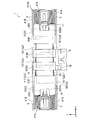
- the linear vibration motor 1 includes a mover 2, a coil 3, a frame body 4, an elastic member 5, and a guide shaft 6. ) To generate vibration by reciprocating linearly along the line.
- the mover 2 includes a magnetic pole part 10 and a weight part 20.
- the weight portions 20 are provided on both sides of the movable element 2 in one axial direction (X-axis direction in the drawing).
- the magnetic pole part 10 includes magnets 11, 12 and 13 and yokes 14 and 15.
- the three magnets 11, 12, 13 and the two yokes 14, 15 are provided.
- the present invention is not limited to this.
- the magnetic pole portion 10 can be constituted by two magnets and one yoke.
- the magnets 11, 12, and 13 have magnetic pole directions along one axial direction (X-axis direction in the drawing).
- the yoke 14 is sandwiched between the same poles of the pair of magnets 11 and 12, and the yoke 15 is sandwiched between the same poles of the pair of magnets 12 and 13.
- the magnetic pole portion 10 can reinforce the connection between the magnets 11, 12, 13 and the yokes 14, 15 by fixing the reinforcing plate 16 to the side surface thereof.
- the coil 3 (3A, 3B) applies a driving force along a uniaxial direction (X-axis direction in the drawing) to the magnetic pole part 10, and in this example, surrounds the yokes 14, 15 of the magnetic pole part 10.
- a driving force along a uniaxial direction X-axis direction in the drawing
- two coils 3A and 3B having opposite winding directions are arranged so as to correspond to the two yokes 14 and 15, but when one yoke is provided, one coil is arranged.
- the frame body 4 includes a magnetic pole frame portion 30 that holds the coil 3.
- the magnetic pole frame part 30 constitutes a magnetic circuit that forms a magnetic flux across the coil 3 together with the magnetic pole part 10 of the mover 2.
- a driving force is applied along the uniaxial direction (X-axis direction in the drawing) to the magnetic pole part 10 of the mover 2 by causing a current to flow through the coil 3 fixed to the magnetic pole frame part 30.
- the frame 4 is provided with an input terminal 18 for inputting a drive signal to the coil 3.
- the magnetic pole frame portion 30 includes an upper surface portion 31, a lower surface portion 32, and a side surface portion 33 so as to surround the coil 3.
- the upper surface portion 31 and the lower surface portion 32 have a plane portion along the X axis and the Y axis
- the side surface portion 33 has a plane portion along the X axis and the Z axis.
- the frame 4 is formed by connecting the upper frame 40 and the lower frame 41 to form a frame that accommodates the mover 2 therein.
- the upper frame body 40 includes the upper surface portion 31 and the side surface portion 33 described above
- the lower frame body 41 includes the lower surface portion 32 described above, the front wall portion 41A, and the side wall portion 41B.
- the guide shaft 6 is a shaft member that guides the vibration of the mover 2 along the uniaxial direction (the X-axis direction in the drawing) within the frame body 4.
- the guide shaft 6 is disposed along the center of gravity axis of the movable element 2 such that one end is fixed to the weight portion 20 and the other end protrudes outside the weight portion 20.
- Guide shafts 6A and 6B are mounted, respectively.
- the other end side of the guide shaft 6 (6A, 6B) is slidably supported by a bearing 17 provided on the frame body 4.
- the guide shaft 6 fixed to the weight portion 20 is shown, but the guide shaft 6 can also be constituted by a single shaft that penetrates the mover 2 along the X-axis direction, for example. In this case, both ends of the guide shaft 6 are fixed to the front wall portion 41 ⁇ / b> A of the frame body 4, and the mover 2 slides on the guide shaft 6.
- the illustrated guide shafts 6A and 6B are fixed in a recess 20A formed in the weight portion 20 along the X-axis direction.
- the recess 20A has a width in the Y-axis direction that allows the bearing 17 to enter, and has a depth in the X-axis direction that allows the amplitude of the mover 2.
- the weight portion 20 includes an engagement recess 20B on the opposite side to the recess 20A, and the magnets 11 and 13 of the magnetic pole portion 10 are engaged and fixed to the engagement recess 20B.
- the elastic member 5 is disposed in the frame body 4 and applies an elastic force to the mover 2 that repels the driving force applied to the magnetic pole portion 10 by the current flowing through the coil 3.
- the illustrated elastic member 5 is disposed between one end (X-axis direction) of the weight portion 20 and the front wall portion 41A of the frame body 4 and is compressed against vibration in the uniaxial direction of the mover 2. It is comprised by the compression spring, and four pieces are arrange
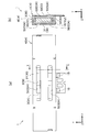
- the mover 2 has a thickness (in the drawing, the X-axis direction) perpendicular to the uniaxial direction (in the drawing, the X-axis direction) (thickness in the drawing). It has a flat shape larger than the thickness in the Z-axis direction. That is, each of the magnetic pole part 10 and the weight part 20 has a flat shape in which the width in the Y-axis direction in the drawing is larger than the thickness in the Z-axis direction in the drawing.
- the outer shape of the frame body 4 has a flat shape in which the width in the Y-axis direction is larger than the thickness in the Z-axis direction as shown in FIG.
- the magnetic pole frame portion 30 in the frame 4 includes an upper surface portion 31 and a lower surface portion 32 facing each other in the thickness direction (Z-axis direction in the drawing) of the mover 2 and in the width direction (Y-axis direction in the drawing) of the mover 2.
- a pair of side portions 33 facing each other is provided.
- the linear vibration motor 1 that slidably supports the movable element 2 with a uniaxial guide shaft 6 (coaxial guide shafts 6A and 6B) is provided around the guide shaft 6 on the magnetic pole portion 10 of the movable element 2.
- a uniaxial guide shaft 6 coaxial guide shafts 6A and 6B
- the flat magnetic pole portion 10 interferes with the coil 3 or the flat weight portion 20 interferes with the inner surface of the frame body 4, and the smooth reciprocating vibration of the mover 2 is performed. You will not be able to get. For this reason, it is necessary to eliminate such rotational force as much as possible.
- the linear vibration motor 1 has a magnetic pole frame portion 30 in which the end in the width direction (Y-axis direction in the drawing) of the magnetic pole portion 10 is close by the rotation of the mover 2 around the guide shaft 6.
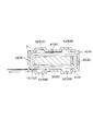
- An adsorption suppression unit 50 that suppresses adsorption of the magnetic pole part 10 is provided in the part.
- the opening part 50A is provided in each of the upper surface part 31 and the lower surface part 32 of the magnetic pole frame part 30. As shown in FIG. The openings 50A are provided at both left and right ends in the Y-axis direction and extend in a long hole shape along one axis direction (X-axis direction in the drawing). The length of the opening 50A in the illustrated X-axis direction is preferably provided, for example, in the vibration range of the yokes 14 and 15 along the illustrated X-axis direction.
- the adsorption suppression unit 50 By providing such an opening 50 ⁇ / b> A as the adsorption suppression unit 50, it is possible to weaken the force that the both end portions in the Y-axis direction of the magnetic pole part 10 are adsorbed by the upper surface part 31 and the lower surface part 32 of the magnetic pole frame part 30. In other words, it is possible to increase the force attracted to the side surface portion 33 of the magnetic pole frame portion 30 with respect to the force attracted to the upper surface portion 31 and the lower surface portion 32 of the magnetic pole frame portion 30 at both ends in the Y-axis direction of the magnetic pole portion 10. it can. By providing such an adsorption suppression unit 50, it is possible to prevent the flat movable element 2 from rotating or tilting around the guide shaft 6.
- a recess 50B may be provided. Similar to the opening 50A described above, the concave portions 50B are provided at the left and right ends in the Y-axis direction on the upper surface portion 31 and the lower surface portion 32 of the magnetic pole frame portion 30, and extend along one axial direction (the X-axis direction in the drawing). Is done.
- Such a recess 50 ⁇ / b> B can also weaken the force with which both end portions in the Y-axis direction of the magnetic pole portion 10 are attracted to the upper surface portion 31 and the lower surface portion 32 of the magnetic pole frame portion 30, similarly to the opening portion 50 ⁇ / b> A.
- both ends in the Y axis direction of the magnetic pole part 10 are side surfaces of the magnetic pole frame part 30 with respect to the force that the both end parts in the Y axis direction of the magnetic pole part 10 are attracted to the upper surface part 31 and the lower surface part 32 of the magnetic pole frame part 30.
- the force attracted by 33 can be strengthened.
- Providing such an adsorption suppression unit 50 can also prevent the flat movable element 2 from rotating or tilting around the guide shaft 6.
- the linear vibration motor 1 can suppress rotation and inclination of the magnetic pole portion 10 around the guide shaft 6 by providing such an adsorption suppression portion 50 in the magnetic pole frame portion 30 of the frame body 4. Even if the (weight part 20) interferes with the inside of the frame body 4, the frictional force between the weight part 20 and the frame body 4 can be reduced. Thereby, the needle
- the adsorption suppression unit 50 is not limited to the opening 50A and the recess 50B described above, and can be obtained by, for example, partially attaching a nonmagnetic material.
- FIG. 6 shows a portable information terminal 100 as an example of an electronic apparatus provided with the linear vibration motor 1 according to the embodiment of the present invention.
- the mobile information terminal 100 including the linear vibration motor 1 that can obtain smooth and stable vibration and can be thinned and compact in the width direction generates an abnormal sound at the start / end of an incoming call or alarm function in a communication function. It can be transmitted to the user with stable vibration that is difficult to perform. Further, the portable information terminal 100 pursuing high portability or design can be obtained by making the linear vibration motor 1 thin and compact in the width direction. Furthermore, since the linear vibration motor 1 has a compact shape in which each part is housed in a rectangular parallelepiped frame 4 with a reduced thickness, the linear vibration motor 1 can be efficiently installed in the thinned portable information terminal 100. .
Landscapes
- Engineering & Computer Science (AREA)
- Power Engineering (AREA)
- Physics & Mathematics (AREA)
- Electromagnetism (AREA)
- Mechanical Engineering (AREA)
- Apparatuses For Generation Of Mechanical Vibrations (AREA)
- Reciprocating, Oscillating Or Vibrating Motors (AREA)
- Telephone Function (AREA)
- Motor Or Generator Frames (AREA)
Abstract
薄型化されたリニア振動モータの可動子がガイドシャフトに沿って円滑に振動できるようにする。リニア振動モータ1は、磁極部10と錘部20を備える可動子2と、磁極部10に対して一軸方向に沿った駆動力を付与するコイル3と、コイル3を保持する磁極枠部30を備える枠体4と、枠体4内に配置されて駆動力に反発する弾性力を可動子2に付与する弾性部材5と、枠体4内で一軸方向に沿った可動子2の振動をガイドするガイドシャフト6とを備え、可動子2は、一軸方向に直交する幅が一軸方向に直交する厚さより大きい偏平形状を有し、ガイドシャフト6回りの可動子2の回転で磁極部10における幅方向の端部が近接する磁極枠部30の一部に、磁極部10の吸着を抑止する吸着抑止部50を設けた。
Description
本発明は、信号入力によって可動子を直線的に往復振動させて振動を発生させるリニア振動モータに関するものである。
振動モータ(或いは振動アクチュエータ)は、通信機器の着信や各種電子機器のアラーム発信などによって振動を発生させ、通信機器の携帯者や各種電子機器に触れる操作者に対して振動によって信号入力の状況を伝えるものであり、携帯電話を含む携帯情報端末などの各種電子機器に装備されている。
振動モータは、各種の形態が開発されているが、直線的な往復振動によって比較的大きな振動を発生させることができるリニア振動モータが注目されている。このリニア振動モータは、直線状のガイドシャフトを設け、これに沿って可動子を振動させる構成を採用することで、安定した振動を得ることができ、またガイドシャフトで可動子を保持することができるので、落下衝撃時の耐損傷性を得ることができる。
このようなリニア振動モータは、筐体に固定したコイルとこのコイル内に配置されるマグネットによって駆動部を構成し、振動方向に沿ってマグネットに錘を連結して可動子を構成し、この可動子に振動方向に沿った貫通孔を形成して、この貫通孔に一本のガイドシャフトを通し、コイルとマグネットによる駆動力とこの駆動力に反発する弾性部材の弾性力によって直線的な往復振動を得るもの(下記特許文献1参照)などが知られている。
携帯電子機器の小型化・薄型化に伴い、それに装備される振動モータには一層の小型化・薄型化の要求がなされている。特に、スマートフォンなどのフラットパネル表示部を備える電子機器においては、表示面と直交する厚さ方向の機器内スペースが限られているので、そこに配備される振動モータには薄型化の高い要求がある。
リニア振動モータの薄型化を考える際には、マグネット体積を十分に確保して所望の駆動力を得ると共に錘の質量を十分に確保して所望の慣性力を得ようとすると、マグネットに錘を連結した可動子を偏平形状にして薄厚化を図ることが考えられる。この場合、可動子の偏平形状に合わせて筐体(カバー)も偏平形状になるが、一軸のガイドシャフトの場合には、ガイドシャフトの軸周りに可動子を回転させる力が作用すると、可動子の外周部とその周囲に設けられるコイルや筐体の内面との間に干渉が生じ易くなり、その干渉が可動子の直線的な往復振動の妨げになる問題があった。
本発明は、このような問題に対処することを課題の一例とするものである。すなわち、ガイドシャフトを備えたリニア振動モータの薄型化を達成すること、薄型化されたリニア振動モータの可動子がガイドシャフトに沿って円滑に振動できるようにすること、等が本発明の目的である。
このような目的を達成するために、本発明は、以下の構成を具備するものである。
磁極部と錘部を備える可動子と、前記磁極部に対して一軸方向に沿った駆動力を付与するコイルと、前記コイルを保持する磁極枠部を備える枠体と、前記枠体内に配置されて前記駆動力に反発する弾性力を前記可動子に付与する弾性部材と、前記枠体内で前記一軸方向に沿った前記可動子の振動をガイドするガイドシャフトとを備え、前記可動子は、前記一軸方向に直交する幅が前記一軸方向に直交する厚さより大きい偏平形状を有し、前記ガイドシャフト回りの前記可動子の回転で前記磁極部における前記幅方向の端部が近接する前記磁極枠部の一部に、前記磁極部の吸着を抑止する吸着抑止部を設けたことを特徴とするリニア振動モータ。
磁極部と錘部を備える可動子と、前記磁極部に対して一軸方向に沿った駆動力を付与するコイルと、前記コイルを保持する磁極枠部を備える枠体と、前記枠体内に配置されて前記駆動力に反発する弾性力を前記可動子に付与する弾性部材と、前記枠体内で前記一軸方向に沿った前記可動子の振動をガイドするガイドシャフトとを備え、前記可動子は、前記一軸方向に直交する幅が前記一軸方向に直交する厚さより大きい偏平形状を有し、前記ガイドシャフト回りの前記可動子の回転で前記磁極部における前記幅方向の端部が近接する前記磁極枠部の一部に、前記磁極部の吸着を抑止する吸着抑止部を設けたことを特徴とするリニア振動モータ。
このような特徴を有する本発明によると、一軸方向に直交する幅が一軸方向に直交する厚さより大きい偏平形状を有する可動子を、ガイドシャフトでガイドしながら一軸方向に往復振動させるので、ガイドシャフトを備えたリニア振動モータの薄型化が可能になる。また、ガイドシャフト回りの可動子の回転で磁極部における幅方向の端部が近接する磁極枠部の一部に、磁極部の吸着を抑止する吸着抑止部を設けているので、磁極部のガイドシャフト回りの回転や傾きを抑えることができ、薄型化されたリニア振動モータの可動子をガイドシャフトに沿って円滑に振動させることができる。
以下、図面を参照して本発明の実施形態を説明する。図1及び図2に示すように、リニア振動モータ1は、可動子2、コイル3、枠体4、弾性部材5、ガイドシャフト6を備えており、可動子2を一軸方向(図示X軸方向)に沿って直線的に往復振動させて振動を発生する。
可動子2は、磁極部10と錘部20を備えている。図示の例では錘部20を可動子2の一軸方向(図示X軸方向)両側に設けているが、これに限らず片側のみであってもよい。磁極部10は、マグネット11,12,13とヨーク14,15を備えている。ここでは、3つのマグネット11,12,13と2つのヨーク14,15を備えているが、これに限らず、例えば2つのマグネットと1つのヨークによって磁極部10を構成することもできる。
マグネット11,12,13は、一軸方向(図示X軸方向)に沿った磁極の向きを有している。また、ヨーク14は、一対のマグネット11,12の同極間に挟まれており、ヨーク15は、一対のマグネット12,13の同極間に挟まれている。この磁極部10は、その側面に補強板16を固着することで、マグネット11,12,13とヨーク14,15の連結を強化することができる。
コイル3(3A,3B)は、磁極部10に対して一軸方向(図示X軸方向)に沿った駆動力を付与するものであり、この例では、磁極部10のヨーク14,15を囲んで配置されている。ここでは2つのヨーク14,15に対応するように巻き方向が逆の2つのコイル3A,3Bを配置しているが、ヨークが1つの場合には1つのコイルが配置される。
枠体4は、コイル3を保持する磁極枠部30を備えている。磁極枠部30は、可動子2の磁極部10と共に、コイル3を横切る磁束を形成する磁気回路を構成している。これによって、磁極枠部30に固定されたコイル3に電流を流すことで、可動子2の磁極部10に一軸方向(図示X軸方向)に沿った駆動力が付与される。枠体4には、コイル3に駆動信号を入力する入力端子18が設けられている。
磁極枠部30は、コイル3を囲むように、上面部31,下面部32,側面部33を備えている。図示の例では、上面部31と下面部32はX軸とY軸に沿った平面部を有しており、側面部33は、X軸とZ軸に沿った平面部を有している。
また、図示の例では、枠体4は、上枠体40と下枠体41を結合することで、内部に可動子2を収容する枠を形成している。上枠体40は、前述した上面部31と側面部33を備えており、下枠体41は、前述した下面部32と、正面壁部41A,側壁部41Bを備えている。
ガイドシャフト6は、枠体4内で一軸方向(図示X軸方向)に沿った可動子2の振動をガイドする軸部材である。図示の例では、ガイドシャフト6は、可動子2の重心軸に沿って、一端が錘部20に固着され他端が錘部20の外側に突出するように配置され、一対の錘部20にそれぞれガイドシャフト6A,6Bが装着されている。ガイドシャフト6(6A,6B)の他端側は枠体4に設けられる軸受17に摺動自在に支持されている。ここでは錘部20に固着されるガイドシャフト6の例を示しているが、ガイドシャフト6は、例えば、可動子2をX軸方向に沿って貫通する一本の軸で構成することもできる。この場合は、ガイドシャフト6の両端が枠体4の正面壁部41Aに固定され、このガイドシャフト6に可動子2が摺動する。
図示のガイドシャフト6A,6Bは、錘部20にX軸方向に沿って形成される凹部20A内に固着されている。凹部20Aは、軸受17が入り込むだけのY軸方向の幅を有しており、可動子2の振幅を許容するだけのX軸方向の深さを有している。また、錘部20は、凹部20Aとは逆側に係合凹部20Bを備えており、この係合凹部20Bには、磁極部10のマグネット11,13が係合されて固定されている。
弾性部材5は、枠体4内に配置されて、コイル3を流れる電流によって磁極部10に付与される駆動力に反発する弾性力を可動子2に付与する。図示の弾性部材5は、錘部20の一軸方向(X軸方向)端部と枠体4の正面壁部41Aとの間に配置され、可動子2の一軸方向の振動に対して圧縮される圧縮バネで構成されており、ガイドシャフト6A,6Bを挟んで左右両側に4個配置されている。
このようなリニア振動モータ1において、可動子2は、一軸方向(図示X軸方向)に直交する幅(図示Y軸方向の幅)が一軸方向(図示X軸方向)に直交する厚さ(図示Z軸方向の厚さ)より大きい偏平形状を有している。すなわち、磁極部10と錘部20がそれぞれ、図示Y軸方向の幅が図示Z軸方向の厚さより大きい偏平形状を有している。
また、この可動子2の偏平形状に対応して、枠体4の外形も図3に示すように、図示Y軸方向の幅が図示Z軸方向の厚さより大きい偏平形状を有している。枠体4における磁極枠部30は、可動子2の厚さ方向(図示Z軸方向)で対面する上面部31と下面部32を備えると共に、可動子2の幅方向(図示Y軸方向)に対面する一対の側面部33を備えている。このように、可動子2及び枠体4を偏平形状にすることで、Z軸方向の厚さを小さくした薄厚のリニア振動モータ1を得ることができる。
ここで、一軸のガイドシャフト6(同軸上のガイドシャフト6A,6B)で可動子2を摺動自在に支持しているリニア振動モータ1は、可動子2の磁極部10にガイドシャフト6回りの回転力が作用すると、偏平形状の磁極部10がコイル3に干渉するか、偏平形状の錘部20が枠体4の内面に干渉することになり、円滑な可動子2の直線的な往復振動を得ることができなくなる。このため、このような回転力を極力排除することが必要になる。
そこで、本発明の実施形態に係るリニア振動モータ1は、ガイドシャフト6回りの可動子2の回転で磁極部10における幅方向(図示Y軸方向)の端部が近接する磁極枠部30の一部に、磁極部10の吸着を抑止する吸着抑止部50を設けている。このような吸着抑止部50を設けることで、磁極部10にガイドシャフト6回りの回転力が作用するのを抑止することができ、可動子2をガイドシャフト6に沿って円滑に直線振動させることができる。
吸着抑止部50としては、図3及び図4に示すように、磁極枠部30の上面部31と下面部32のそれぞれに開口部50Aを設ける。開口部50Aは、Y軸方向の左右両端部に設けられ、一軸方向(図示X軸方向)に沿って長孔状に延設される。この開口部50Aの図示X軸方向の長さは、例えばヨーク14,15の図示X軸方向に沿った振動範囲に設けることが好ましい。
吸着抑止部50として、このような開口部50Aを設けることで、磁極部10のY軸方向両端部が磁極枠部30の上面部31と下面部32に吸着される力を弱めることができる。言い換えれば、磁極部10のY軸方向両端部が磁極枠部30の上面部31と下面部32に吸着される力に対して磁極枠部30の側面部33に吸着される力を強めることができる。このような吸着抑止部50を設けることで、偏平形状の可動子2がガイドシャフト6回りに回転又は傾斜するのを抑止することができる。
また、吸着抑止部50としては、図5に示すように、凹部50Bを設けてもよい。凹部50Bは、前述した開口部50Aと同様に、磁極枠部30の上面部31と下面部32においてY軸方向の左右両端部に設けられ、一軸方向(図示X軸方向)に沿って延設される。このような凹部50Bによっても、開口部50Aと同様に、磁極部10のY軸方向両端部が磁極枠部30の上面部31と下面部32に吸着される力を弱めることができる。言い換えれば、磁極部10のY軸方向両端部が磁極枠部30の上面部31と下面部32に吸着される力に対して磁極部10のY軸方向両端部が磁極枠部30の側面部33に吸着される力を強めることができる。このような吸着抑止部50を設けることでも、偏平形状の可動子2がガイドシャフト6回りに回転又は傾斜するのを抑止することができる。
リニア振動モータ1は、このような吸着抑止部50を枠体4の磁極枠部30に設けることで、磁極部10のガイドシャフト6回りの回転や傾きを抑えることができ、また、可動子2(錘部20)が枠体4の内側に干渉したとしても、錘部20と枠体4との摩擦力を低減させることができる。これにより、薄型化されたリニア振動モータ1の可動子2をガイドシャフト6に沿って円滑に振動させることができる。吸着抑止部50は、前述した開口部50Aや凹部50Bに限らず、例えば、非磁性体を部分的に貼り付けることなどでも得ることができる。
図6は、本発明の実施形態に係るリニア振動モータ1を備えた電子機器の一例として、携帯情報端末100を示している。円滑で安定した振動が得られ薄型化や幅方向のコンパクト化が可能なリニア振動モータ1を備える携帯情報端末100は、通信機能における着信やアラーム機能などの動作開始・終了時を異音が発生しにくい安定した振動で使用者に伝えることができる。また、リニア振動モータ1の薄型化・幅方向のコンパクト化によって高い携帯性或いはデザイン性を追求した携帯情報端末100を得ることができる。更に、リニア振動モータ1は、厚さを抑えた直方体形状の枠体4内に各部を収容したコンパクト形状であるから、薄型化された携帯情報端末100の内部にスペース効率よく装備することができる。
以上、本発明の実施の形態について図面を参照して詳述してきたが、具体的な構成はこれらの実施の形態に限られるものではなく、本発明の要旨を逸脱しない範囲の設計の変更等があっても本発明に含まれる。
1:リニア振動モータ,2:可動子,3(3A,3B):コイル,4:枠体,
5:弾性部材,6(6A,6B):ガイドシャフト,
10:磁極部,11,12,13:マグネット,14,15:ヨーク,
16:補強板,17:軸受,18:入力端子,
20:錘部,20A:凹部,20B:係合凹部,
30:磁極枠部,31:上面部,32:下面部,33:側面部,
40:上枠体,41:下枠体,41A:正面壁部,41B:側壁部
50:吸着抑止部,50A:開口部,50B:凹部,100:携帯情報端末
5:弾性部材,6(6A,6B):ガイドシャフト,
10:磁極部,11,12,13:マグネット,14,15:ヨーク,
16:補強板,17:軸受,18:入力端子,
20:錘部,20A:凹部,20B:係合凹部,
30:磁極枠部,31:上面部,32:下面部,33:側面部,
40:上枠体,41:下枠体,41A:正面壁部,41B:側壁部
50:吸着抑止部,50A:開口部,50B:凹部,100:携帯情報端末
Claims (6)
- 磁極部と錘部を備える可動子と、
前記磁極部に対して一軸方向に沿った駆動力を付与するコイルと、
前記コイルを保持する磁極枠部を備える枠体と、
前記枠体内に配置されて前記駆動力に反発する弾性力を前記可動子に付与する弾性部材と、
前記枠体内で前記一軸方向に沿った前記可動子の振動をガイドするガイドシャフトとを備え、
前記可動子は、前記一軸方向に直交する幅が前記一軸方向に直交する厚さより大きい偏平形状を有し、
前記ガイドシャフト回りの前記可動子の回転で前記磁極部における前記幅方向の端部が近接する前記磁極枠部の一部に、前記磁極部の吸着を抑止する吸着抑止部を設けたことを特徴とするリニア振動モータ。 - 前記磁極枠部は、前記可動子の幅方向に沿った上面部と下面部を備え、
前記吸着抑止部は、前記上面部と前記下面部のそれぞれに設けられ前記一軸方向に沿って延設された開口部又は凹部であることを特徴とする請求項1記載のリニア振動モータ。 - 前記磁極部は、前記一軸方向に沿った磁極の向きを有する一対のマグネットの同極間に挟まれるヨークを備えることを特徴とする請求項2記載のリニア振動モータ。
- 前記可動子の前記一軸方向端部に前記錘部が配置され、
前記ガイドシャフトは、前記可動子の重心軸に沿って、一端が前記錘部に固着され他端が前記錘部の外側に突出して配置され、
前記ガイドシャフトの他端側が前記枠体に設けられる軸受に摺動自在に支持されることを特徴とする請求項3記載のリニア振動モータ。 - 磁極部と錘部を備える可動子と、
前記磁極部に対して一軸方向に沿った駆動力を付与するコイルと、
前記コイルを保持する磁極枠部を備える枠体と、
前記枠体内に配置されて前記駆動力に反発する弾性力を前記可動子に付与する弾性部材と、
前記枠体内で前記一軸方向に沿った前記可動子の振動をガイドするガイドシャフトとを備え、
前記可動子は、前記一軸方向に直交する幅が前記一軸方向に直交する厚さより大きい偏平形状を有し、
前記枠体の磁極枠部は、前記可動子の厚さ方向で対面する上面部と下面部を備えると共に、前記可動子の幅方向に対面する側面部を備え、
前記磁極部における前記幅方向の端部が前記上面部と前記下面部に吸着される力に対して、前記磁極部における前記幅方向の端部が前記側面部に吸着される力が強いことを特徴とするリニア振動モータ。 - 請求項1~5のいずれかに1項に記載されたリニア振動モータを備えた携帯情報端末。
Priority Applications (1)
| Application Number | Priority Date | Filing Date | Title |
|---|---|---|---|
| CN201580062662.4A CN107107110A (zh) | 2014-11-25 | 2015-11-24 | 线性振动马达 |
Applications Claiming Priority (2)
| Application Number | Priority Date | Filing Date | Title |
|---|---|---|---|
| JP2014-238220 | 2014-11-25 | ||
| JP2014238220A JP6297478B2 (ja) | 2014-11-25 | 2014-11-25 | リニア振動モータ |
Publications (1)
| Publication Number | Publication Date |
|---|---|
| WO2016084809A1 true WO2016084809A1 (ja) | 2016-06-02 |
Family
ID=56074363
Family Applications (1)
| Application Number | Title | Priority Date | Filing Date |
|---|---|---|---|
| PCT/JP2015/082952 WO2016084809A1 (ja) | 2014-11-25 | 2015-11-24 | リニア振動モータ |
Country Status (3)
| Country | Link |
|---|---|
| JP (1) | JP6297478B2 (ja) |
| CN (1) | CN107107110A (ja) |
| WO (1) | WO2016084809A1 (ja) |
Cited By (1)
| Publication number | Priority date | Publication date | Assignee | Title |
|---|---|---|---|---|
| WO2018180946A1 (ja) * | 2017-03-30 | 2018-10-04 | 日本電産サンキョー株式会社 | アクチュエータ |
Families Citing this family (3)
| Publication number | Priority date | Publication date | Assignee | Title |
|---|---|---|---|---|
| CN106329871A (zh) * | 2016-09-30 | 2017-01-11 | 歌尔股份有限公司 | 线性振动马达以及电子设备 |
| JP2019180149A (ja) * | 2018-03-30 | 2019-10-17 | 日本電産サンキョー株式会社 | アクチュエータ |
| CN213461503U (zh) * | 2020-09-28 | 2021-06-15 | 瑞声科技(新加坡)有限公司 | 线性马达 |
Citations (2)
| Publication number | Priority date | Publication date | Assignee | Title |
|---|---|---|---|---|
| JP2010191332A (ja) * | 2009-02-20 | 2010-09-02 | Nidec Sankyo Corp | レンズ駆動装置 |
| JP2014028349A (ja) * | 2012-07-31 | 2014-02-13 | Nidec Copal Corp | 振動アクチュエータ |
Family Cites Families (4)
| Publication number | Priority date | Publication date | Assignee | Title |
|---|---|---|---|---|
| JP4422957B2 (ja) * | 2002-10-31 | 2010-03-03 | キヤノン株式会社 | 位置決め装置 |
| JP4875133B2 (ja) * | 2009-10-29 | 2012-02-15 | 日本電産コパル株式会社 | 振動アクチュエータ |
| JP5888867B2 (ja) * | 2011-03-31 | 2016-03-22 | 日本電産コパル株式会社 | 振動アクチュエータ |
| JP2013110846A (ja) * | 2011-11-21 | 2013-06-06 | Minebea Co Ltd | モータ |
-
2014
- 2014-11-25 JP JP2014238220A patent/JP6297478B2/ja not_active Expired - Fee Related
-
2015
- 2015-11-24 WO PCT/JP2015/082952 patent/WO2016084809A1/ja active Application Filing
- 2015-11-24 CN CN201580062662.4A patent/CN107107110A/zh active Pending
Patent Citations (2)
| Publication number | Priority date | Publication date | Assignee | Title |
|---|---|---|---|---|
| JP2010191332A (ja) * | 2009-02-20 | 2010-09-02 | Nidec Sankyo Corp | レンズ駆動装置 |
| JP2014028349A (ja) * | 2012-07-31 | 2014-02-13 | Nidec Copal Corp | 振動アクチュエータ |
Cited By (4)
| Publication number | Priority date | Publication date | Assignee | Title |
|---|---|---|---|---|
| WO2018180946A1 (ja) * | 2017-03-30 | 2018-10-04 | 日本電産サンキョー株式会社 | アクチュエータ |
| JPWO2018180946A1 (ja) * | 2017-03-30 | 2020-02-06 | 日本電産サンキョー株式会社 | アクチュエータ |
| US11283338B2 (en) | 2017-03-30 | 2022-03-22 | Nidec Sankyo Corporation | Actuator |
| JP7039465B2 (ja) | 2017-03-30 | 2022-03-22 | 日本電産サンキョー株式会社 | アクチュエータ |
Also Published As
| Publication number | Publication date |
|---|---|
| CN107107110A (zh) | 2017-08-29 |
| JP2016097383A (ja) | 2016-05-30 |
| JP6297478B2 (ja) | 2018-03-20 |
Similar Documents
| Publication | Publication Date | Title |
|---|---|---|
| JP6434028B2 (ja) | リニア振動モータ | |
| JP6421089B2 (ja) | リニア振動モータ及び該リニア振動モータを備える携帯電子機器 | |
| WO2016017584A1 (ja) | リニア振動モータ | |
| WO2016114383A1 (ja) | リニア振動モータ | |
| WO2016114384A1 (ja) | 振動アクチュエータ | |
| JP6010080B2 (ja) | リニア振動モータ | |
| WO2016017586A1 (ja) | リニア振動モータ | |
| WO2016167297A1 (ja) | リニア振動モータ | |
| JP6517649B2 (ja) | リニア振動モータ | |
| WO2016084809A1 (ja) | リニア振動モータ | |
| WO2017002950A1 (ja) | リニア振動モータ | |
| WO2017057315A1 (ja) | リニア振動モータ | |
| JP6663762B2 (ja) | リニア振動モータ | |
| WO2016084807A1 (ja) | リニア振動モータ | |
| WO2017026373A1 (ja) | リニア振動モータ及び該リニア振動モータを備える携帯電子機器 | |
| JP6333186B2 (ja) | リニア振動モータ | |
| JP2017221905A (ja) | リニア振動モータ | |
| WO2017002949A1 (ja) | リニア振動モータ | |
| WO2018008280A1 (ja) | リニア振動モータ | |
| JP6333187B2 (ja) | リニア振動モータ | |
| WO2017057193A1 (ja) | リニア振動モータ | |
| JP2006068688A (ja) | 振動アクチュエータ | |
| JP2017175838A (ja) | リニア振動モータ | |
| JP6479595B2 (ja) | リニア振動モータ | |
| JP2017017875A (ja) | リニア振動モータ |
Legal Events
| Date | Code | Title | Description |
|---|---|---|---|
| 121 | Ep: the epo has been informed by wipo that ep was designated in this application |
Ref document number: 15862647 Country of ref document: EP Kind code of ref document: A1 |
|
| NENP | Non-entry into the national phase |
Ref country code: DE |
|
| 122 | Ep: pct application non-entry in european phase |
Ref document number: 15862647 Country of ref document: EP Kind code of ref document: A1 |