WO2016084536A1 - タイヤ - Google Patents
タイヤ Download PDFInfo
- Publication number
- WO2016084536A1 WO2016084536A1 PCT/JP2015/080146 JP2015080146W WO2016084536A1 WO 2016084536 A1 WO2016084536 A1 WO 2016084536A1 JP 2015080146 W JP2015080146 W JP 2015080146W WO 2016084536 A1 WO2016084536 A1 WO 2016084536A1
- Authority
- WO
- WIPO (PCT)
- Prior art keywords
- tire
- resin layer
- covering
- cord
- coating
- Prior art date
Links
Images


Classifications
-
- B—PERFORMING OPERATIONS; TRANSPORTING
- B60—VEHICLES IN GENERAL
- B60C—VEHICLE TYRES; TYRE INFLATION; TYRE CHANGING; CONNECTING VALVES TO INFLATABLE ELASTIC BODIES IN GENERAL; DEVICES OR ARRANGEMENTS RELATED TO TYRES
- B60C9/00—Reinforcements or ply arrangement of pneumatic tyres
- B60C9/18—Structure or arrangement of belts or breakers, crown-reinforcing or cushioning layers
- B60C9/20—Structure or arrangement of belts or breakers, crown-reinforcing or cushioning layers built-up from rubberised plies each having all cords arranged substantially parallel
- B60C9/22—Structure or arrangement of belts or breakers, crown-reinforcing or cushioning layers built-up from rubberised plies each having all cords arranged substantially parallel the plies being arranged with all cords disposed along the circumference of the tyre
-
- B—PERFORMING OPERATIONS; TRANSPORTING
- B60—VEHICLES IN GENERAL
- B60C—VEHICLE TYRES; TYRE INFLATION; TYRE CHANGING; CONNECTING VALVES TO INFLATABLE ELASTIC BODIES IN GENERAL; DEVICES OR ARRANGEMENTS RELATED TO TYRES
- B60C5/00—Inflatable pneumatic tyres or inner tubes
- B60C5/01—Inflatable pneumatic tyres or inner tubes without substantial cord reinforcement, e.g. cordless tyres, cast tyres
-
- B—PERFORMING OPERATIONS; TRANSPORTING
- B60—VEHICLES IN GENERAL
- B60C—VEHICLE TYRES; TYRE INFLATION; TYRE CHANGING; CONNECTING VALVES TO INFLATABLE ELASTIC BODIES IN GENERAL; DEVICES OR ARRANGEMENTS RELATED TO TYRES
- B60C15/00—Tyre beads, e.g. ply turn-up or overlap
- B60C15/04—Bead cores
-
- B—PERFORMING OPERATIONS; TRANSPORTING
- B60—VEHICLES IN GENERAL
- B60C—VEHICLE TYRES; TYRE INFLATION; TYRE CHANGING; CONNECTING VALVES TO INFLATABLE ELASTIC BODIES IN GENERAL; DEVICES OR ARRANGEMENTS RELATED TO TYRES
- B60C9/00—Reinforcements or ply arrangement of pneumatic tyres
- B60C9/18—Structure or arrangement of belts or breakers, crown-reinforcing or cushioning layers
- B60C9/20—Structure or arrangement of belts or breakers, crown-reinforcing or cushioning layers built-up from rubberised plies each having all cords arranged substantially parallel
- B60C9/22—Structure or arrangement of belts or breakers, crown-reinforcing or cushioning layers built-up from rubberised plies each having all cords arranged substantially parallel the plies being arranged with all cords disposed along the circumference of the tyre
- B60C9/2204—Structure or arrangement of belts or breakers, crown-reinforcing or cushioning layers built-up from rubberised plies each having all cords arranged substantially parallel the plies being arranged with all cords disposed along the circumference of the tyre obtained by circumferentially narrow strip winding
-
- B—PERFORMING OPERATIONS; TRANSPORTING
- B60—VEHICLES IN GENERAL
- B60C—VEHICLE TYRES; TYRE INFLATION; TYRE CHANGING; CONNECTING VALVES TO INFLATABLE ELASTIC BODIES IN GENERAL; DEVICES OR ARRANGEMENTS RELATED TO TYRES
- B60C9/00—Reinforcements or ply arrangement of pneumatic tyres
- B60C9/18—Structure or arrangement of belts or breakers, crown-reinforcing or cushioning layers
- B60C9/20—Structure or arrangement of belts or breakers, crown-reinforcing or cushioning layers built-up from rubberised plies each having all cords arranged substantially parallel
- B60C9/22—Structure or arrangement of belts or breakers, crown-reinforcing or cushioning layers built-up from rubberised plies each having all cords arranged substantially parallel the plies being arranged with all cords disposed along the circumference of the tyre
- B60C2009/2238—Physical properties or dimensions of the ply coating rubber
- B60C2009/2242—Modulus; Hardness; Loss modulus or "tangens delta"
-
- B—PERFORMING OPERATIONS; TRANSPORTING
- B60—VEHICLES IN GENERAL
- B60C—VEHICLE TYRES; TYRE INFLATION; TYRE CHANGING; CONNECTING VALVES TO INFLATABLE ELASTIC BODIES IN GENERAL; DEVICES OR ARRANGEMENTS RELATED TO TYRES
- B60C9/00—Reinforcements or ply arrangement of pneumatic tyres
- B60C9/18—Structure or arrangement of belts or breakers, crown-reinforcing or cushioning layers
- B60C9/20—Structure or arrangement of belts or breakers, crown-reinforcing or cushioning layers built-up from rubberised plies each having all cords arranged substantially parallel
- B60C9/22—Structure or arrangement of belts or breakers, crown-reinforcing or cushioning layers built-up from rubberised plies each having all cords arranged substantially parallel the plies being arranged with all cords disposed along the circumference of the tyre
- B60C2009/2238—Physical properties or dimensions of the ply coating rubber
- B60C2009/2247—Thickness
-
- B—PERFORMING OPERATIONS; TRANSPORTING
- B60—VEHICLES IN GENERAL
- B60C—VEHICLE TYRES; TYRE INFLATION; TYRE CHANGING; CONNECTING VALVES TO INFLATABLE ELASTIC BODIES IN GENERAL; DEVICES OR ARRANGEMENTS RELATED TO TYRES
- B60C15/00—Tyre beads, e.g. ply turn-up or overlap
- B60C15/04—Bead cores
- B60C2015/048—Polygonal cores characterised by the winding sequence
Definitions
- the present invention relates to a tire, and more particularly to a tire in which a tire frame member is formed using a resin material.
- resin materials for example, thermoplastic resins, thermoplastic elastomers, etc.
- tire materials are required to be used as tire materials because of weight reduction, ease of molding, and ease of recycling.
- Japanese Patent Laid-Open No. 03-143701 discloses a tire in which a tire frame member is formed of a thermoplastic resin material.
- the reinforcing cord When the reinforcing cord is covered with the covering resin material, it is desirable to firmly bond the reinforcing cord and the covering resin material with an adhesive resin material interposed therebetween.
- this coating resin material a relatively soft resin material tends to be used so that it can follow the tire deformation during rolling of the tire. Although such a soft resin material is excellent in followability to deformation, it tends to be difficult to suppress the progress of the scratch when a scratch or the like occurs.
- the present invention has been made in consideration of the above facts, and it is an object of the present invention to provide a tire capable of suppressing the progress speed until a scratch generated in the coating resin layer covering the reinforcing cord reaches the reinforcing cord.
- the tire of the first aspect of the present invention is formed of an annular tire skeleton member formed of a skeleton resin material, a reinforcing cord provided in the tire skeleton member, extending in the tire circumferential direction, and a coating resin material.
- a covering cord member that is disposed between the reinforcing cord and the covering resin layer and includes a bonding resin layer that is thicker than the covering resin layer.
- the layer thickness of the bonding resin layer is larger than the layer thickness of the coating resin layer, for example, the layer thickness of the bonding resin layer is equal to or less than the layer thickness of the coating resin layer.
- the bonding resin layer becomes harder than those obtained. Thereby, for example, even if a flaw occurs in the coating resin layer, the progress speed of the flaw is suppressed by the bonding resin layer. For this reason, the advancing speed until the damage
- a tire according to a second aspect of the present invention is the tire according to the first aspect, wherein the tire frame member includes a bead portion, a side portion that is continuous with the outer side in the tire radial direction of the bead portion, and an inner side in the tire width direction of the side portion.
- a continuous crown portion, and the covering cord member is spirally wound around an outer periphery of the crown portion.
- the coated cord member is spirally wound around the outer periphery of the crown portion of the tire frame member, the tire circumferential rigidity of the crown portion is improved.
- the coating resin material has thermoplasticity, and the coating resin layer and the crown portion are joined by thermal welding.
- the covering resin layer of the covering cord member and the crown portion of the tire frame member are bonded together by heat welding, the bonding strength between the covering resin layer and the crown portion is improved.
- a tire according to a fourth aspect of the present invention is the tire according to the first aspect, wherein the tire frame member includes a bead portion, a side portion continuous to a tire radial direction outer side of the bead portion, and an inner side in the tire width direction of the side portion.
- a continuous crown part, and the covering cord member is embedded in the bead part.
- the circumferential rigidity of the bead portion of the tire frame member is improved.
- the skeleton resin material has thermoplasticity, and the coating resin layer and the bead portion are joined by thermal welding.
- the covering resin layer of the covering cord member and the bead portion of the tire frame member are bonded by heat welding, the bonding strength between the covering resin layer and the bead portion is improved.
- the thickness of the bonding resin layer is 500 ⁇ m to 5 mm.
- the bonding resin layer can be further hardened. Therefore, for example, even if a flaw occurs in the coating resin layer, the progress speed of the flaw is further suppressed by the bonding resin layer.
- an arrow TW indicates a tire width direction
- an arrow TR indicates a tire radial direction (a direction orthogonal to a tire rotation axis (not shown))
- an arrow TC indicates a tire circumferential direction.
- the side close to the tire rotation axis along the tire radial direction is referred to as “tire radial inner side”
- the side far from the tire rotation axis along the tire radial direction is referred to as “tire radial outer side”.
- the side close to the tire equatorial plane CL along the tire width direction is “inner side in the tire width direction”, and the opposite side, that is, the side far from the tire equatorial plane CL along the tire width direction is “outside in the tire width direction”. ".
- the dimension measuring method of each part is based on the method as described in the 2014 edition YEAR BOOK issued by JATMA (Japan Automobile Tire Association).
- the tire 10 of the first embodiment is a pneumatic tire that is used by being filled with air, and has substantially the same cross-sectional shape as a conventional general rubber pneumatic tire. .
- the tire 10 of this embodiment includes a tire skeleton member 17 that is a skeleton portion of the tire 10.
- the tire frame member 17 is formed by annularly forming a frame resin material.
- the tire frame member 17 is connected to a pair of bead portions 12 arranged at intervals in the tire width direction, a side portion 14 connected to the outer side of the bead portion 12 in the tire radial direction, and an inner side of the side portion 14 in the tire width direction.
- a crown portion 16 that connects the outer ends in the tire radial direction of the respective side portions 14.
- the circumferential direction, the width direction, and the radial direction of the tire frame member 17 correspond to the tire circumferential direction, the tire width direction, and the tire radial direction, respectively.
- the tire frame member 17 is formed using a frame resin material as a main raw material.
- This skeleton resin material does not include vulcanized rubber.
- the resin material for the skeleton include thermoplastic resins (including thermoplastic elastomers), thermosetting resins, and other general-purpose resins, as well as engineering plastics (including super engineering plastics).
- Thermoplastic resin refers to a polymer compound that softens and flows as the temperature rises and becomes relatively hard and strong when cooled.
- the material softens and flows with increasing temperature, and becomes relatively hard and strong when cooled, and a high molecular compound having rubber-like elasticity is a thermoplastic elastomer, and the material increases with increasing temperature. Is softened, fluidized, and becomes a relatively hard and strong state when cooled, and a high molecular compound having no rubber-like elasticity is distinguished as a thermoplastic resin that is not an elastomer.
- Thermoplastic resins include polyolefin-based thermoplastic elastomers (TPO), polystyrene-based thermoplastic elastomers (TPS), polyamide-based thermoplastic elastomers (TPA), polyurethane-based thermoplastic elastomers (TPU), and polyesters.
- TPO polyolefin-based thermoplastic elastomers
- TPS polystyrene-based thermoplastic elastomers
- TPA polyamide-based thermoplastic elastomers
- TPU polyurethane-based thermoplastic elastomers
- polyesters polyesters.
- TSV dynamically crosslinked thermoplastic elastomer
- polyolefin thermoplastic resin polystyrene thermoplastic resin
- polyamide thermoplastic resin polyamide thermoplastic resin
- polyester thermoplastic resin etc. Can be mentioned.
- the deflection temperature under load specified at ISO 75-2 or ASTM D648 (at 0.45 MPa load) is 78 ° C. or higher, and the tensile yield strength specified by JIS K7161 is 10 MPa.
- the tensile fracture elongation similarly defined in JIS K7161 is 50% or more. What has Vicat softening temperature (A method) prescribed
- regulated to JISK7206 of 130 degreeC can be used.
- thermosetting resin refers to a polymer compound that forms a three-dimensional network structure as the temperature rises and cures.
- a thermosetting resin a phenol resin, an epoxy resin, a melamine resin, a urea resin etc. are mentioned, for example.
- thermoplastic resins including thermoplastic elastomers
- thermosetting resins thermosetting resins
- skeleton resin materials include (meth) acrylic resins, EVA resins, vinyl chloride resins, fluorine resins, silicone resins.
- a general-purpose resin such as a resin may be used.
- the tire skeleton member 17 has different characteristics for each part (bead portion 12, side portion 14, crown portion 16 and the like) of the tire skeleton member 17. It may be formed of a resin material.
- the tire frame member 17 is formed of a thermoplastic resin.
- the bead portion 12 is a portion that fits into a standard rim (not shown) via a covering rubber 24, and an annular bead core 18 that extends along the tire circumferential direction is embedded therein.
- the bead core 18 is configured by a bead cord (not shown) such as a metal cord (for example, a steel cord), an organic fiber cord, a resin-coated organic fiber cord, or a hard resin.
- the bead core 18 may be omitted if the rigidity of the bead portion 12 can be sufficiently secured.
- the side portion 14 is a portion constituting the side portion of the tire 10 and is gently curved so as to protrude outward from the bead portion 12 toward the crown portion 16 in the tire width direction.
- the crown portion 16 is a portion that supports a tread 30 (described later) disposed on the outer side in the tire radial direction, and has an outer peripheral surface that is substantially flat along the tire width direction.
- a belt layer 28 is disposed outside the crown portion 16 in the tire radial direction.
- the belt layer 28 is formed by winding the covering cord member 26 spirally in the tire circumferential direction. The details of the covering cord member 26 will be described later.
- a tread 30 is disposed outside the belt layer 28 in the tire radial direction.
- the tread 30 covers the belt layer 28. Further, the tread 30 is formed with a tread pattern (not shown) on the contact surface with the road surface.
- the tire frame member 17 is provided with a covering rubber 24 extending from the outer surface of the side portion 14 to the inner surface of the bead portion 12.
- a rubber material constituting the covering rubber 24 a rubber material having higher weather resistance and sealability with a standard rim than the tire frame member 17 is used.
- the outer surface of the tire frame member 17 is all covered with the tread 30 and the covering rubber 24.
- the covering cord member 26 includes a reinforcing cord 32 extending in the tire circumferential direction, a covering resin layer 34 covering the reinforcing cord 32, and between the reinforcing cord 32 and the covering resin layer 34. And a bonding resin layer 36 for bonding (adhering) the reinforcing cord 32 and the covering resin layer 34 to each other.
- the reinforcing cord 32 is composed of a monofilament (single wire) such as a metal fiber or an organic fiber, or a multifilament (twisted wire) obtained by twisting these fibers.
- the reinforcing cord 32 is a metal cord made of metal fibers.
- the coating resin layer 34 is made of a coating resin material.
- the resin material for covering the same material as the resin material for skeleton forming the tire skeleton member 17 can be used.
- a thermoplastic resin is used as the coating resin material, and the coating resin layer 34 is joined to the crown portion 16 by thermal welding.
- the coating resin layer 34 and the crown portion 16 are bonded by heat welding, it is preferable from the viewpoint of bonding strength that the coating resin material and the skeleton resin material are the same resin material.
- the present invention is not limited to this configuration, and the coating resin material and the skeleton resin material may be different resin materials.
- the covering resin layer 34 has a substantially square cross-sectional shape.
- the cross-sectional shape of the coating resin layer 34 is not limited to a substantially square shape. For example, it may have a circular cross section or a trapezoidal cross section.
- the bonding resin layer 36 is formed of a bonding resin material having a higher elastic modulus than the coating resin material and having excellent adhesion to the reinforcing cord 32.
- the “elastic modulus” refers to a tensile elastic modulus defined in JIS K7161.
- the elastic modulus of the bonding resin layer 36 is preferably set to 1 to 5 times the elastic modulus of the covering resin layer 34.
- bonding resin materials include modified olefin resins (modified polyethylene resins, modified polypropylene resins, etc.), polyamide resins, polyurethane resins, polyester resins, ethylene-ethyl acrylate copolymers, ethylene-acetic acid. What contains 1 type, or 2 or more types of thermoplastic resins, such as a vinyl copolymer, as a main component (main ingredient) is mentioned. Among these, from the viewpoint of adhesion to the reinforcing metal cord member and the coating composition, from modified olefin resins, polyester resins, ethylene-ethyl acrylate copolymers, and ethylene-vinyl acetate copolymers.
- modified olefin resins modified polyethylene resins, modified polypropylene resins, etc.
- polyamide resins polyurethane resins
- polyester resins ethylene-ethyl acrylate copolymers
- ethylene-acetic acid ethylene-acetic acid.
- a hot melt adhesive containing at least one selected from the above is preferable, and a modified olefin resin (acid-modified olefin resin) acid-modified with an unsaturated carboxylic acid is more preferable.
- modified olefin resin acid-modified with an unsaturated carboxylic acid means a modified olefin resin obtained by graft copolymerization of an unsaturated carboxylic acid with a polyolefin.
- these olefinic thermoplastic elastomers those having an elastic modulus of 140 MPa to 950 MPa are preferably used.
- the layer thickness T1 of the bonding resin layer 36 is larger (larger) than the layer thickness T2 of the coating resin layer 34.
- the “layer thickness” refers to the thinnest portion of the thickness measured along the radial direction of the reinforcing cord 32 from the center of the reinforcing cord 32.
- the layer thickness T1 of the bonding resin layer 36 is set in the range of 500 ⁇ m to 5 mm.
- the covering cord member 26 is wound around the outer periphery of the crown portion 16 in the tire circumferential direction and joined by thermal welding.
- the covering cord member 26 is wound around the outer periphery of the crown portion 16 without a gap in the tire width direction, and adjacent portions in the tire width direction are joined together by heat welding.
- this invention is not limited to the said structure, For example, it is good also as a structure by which the covering cord member 26 is wound with a clearance gap in the tire width direction.
- a pair of tire skeleton halves (not shown) are formed by injection molding the skeleton resin material and dividing the tire skeleton member 17 in half.
- the injection molding of the tire frame half is performed in a state where the bead core 18 formed in advance is arranged at a predetermined position in the mold. For this reason, a bead core 18 is embedded in the bead portion 12 of the molded tire frame half.
- an unvulcanized coated rubber to be the coated rubber 24 is pasted from the outer surface of the side portion 14 of the tire frame member 17 to the inner surface of the bead portion 12. Thereby, the tire frame member 17 with unvulcanized coated rubber is formed.
- a pair of tire skeleton halves are formed and the tire skeleton members are formed by joining the pair of tire skeleton halves together, but the present invention is not limited to this configuration.
- the tire frame member 17 may be formed by dividing it into three or more parts, and the divided parts may be joined to form the tire frame member 17. Further, the tire frame member 17 may be formed without being divided.
- the covering cord member forming step First, the reinforcing cord 32 is coated with a molten adhesive resin material, and then coated with the molten covering resin material before the adhesive resin material is solidified. When the adhesive resin material and the coating resin material are cooled and solidified, the bonding resin layer 36 and the coating resin layer 34 are formed on the outer periphery of the reinforcing cord 32 to form the coated cord member 26.
- the covering cord member forming step is not limited to the above-described configuration, and may be a configuration in which the adhesive resin material covering the reinforcing cord 32 is cooled and solidified and then covered with a molten covering resin material.
- the shapes of the coating resin layer 34 and the bonding resin layer 36 can be changed by changing the shape of the extrusion port of an extruder (not shown).
- the thickness of each of the coating resin layer 34 and the bonding resin layer 36 can be adjusted by changing the opening amount of the extrusion port of the extruder.
- the opening amount of the extrusion port of an extruder is changed so that the layer thickness T1 of the bonding resin layer 36 is thicker (larger) than the layer thickness T2 of the coating resin layer 34. .
- the belt layer 28 is formed on the outer periphery of the tire frame member 17. Specifically, the belt layer 28 is formed by winding the covering cord member 26 around the crown portion 16 of the tire frame member 17 in a spiral manner.
- the reinforcing cord 32 is wound around the crown portion 16 while melting the portion of the coating resin layer 34 that contacts the outer surface of the crown portion 16, so that after the cooling and solidification of the coating resin material, the crown portion 16 is heated. It is firmly joined by welding.
- an unvulcanized tread rubber (not shown) that becomes the tread 30 is arranged on the outer side in the tire radial direction of the belt layer 28.
- a belt-shaped unvulcanized rubber tread for one round of the tire is wound around the outer periphery of the tire frame member 17 and bonded to the outer peripheral surfaces of the belt layer 28 and the tire frame member 17 using an adhesive.
- the vulcanization process will be described.
- the unvulcanized tread rubber and the unvulcanized coated rubber adhered to the tire frame member 17 are vulcanized.
- the tire frame member 17 is set in a vulcanizer, and the unvulcanized tread rubber and the unvulcanized coated rubber are heated and vulcanized at a predetermined temperature for a predetermined time.
- the unvulcanized coated rubber and the unvulcanized tread are vulcanized to reach the vulcanization degree of the final product.
- the vulcanized tire 10 is taken out from the vulcanizer. Thereby, the tire 10 is completed.
- a belt layer 28 is disposed on the crown portion 16 of the tire frame member 17 and an unvulcanized tread 30 is disposed on the belt layer 28 before the unvulcanized coated rubber is attached to the tire frame member 17. Also good. Moreover, before joining a pair of tire halves, it is good also as a structure which affixes unvulcanized coating rubber to a tire half.
- the layer thickness T1 of the bonding resin layer 36 is thicker than the layer thickness T2 of the coating resin layer 34, for example, compared with the case where the layer thickness T1 is set to be equal to or less than the layer thickness T2.
- the resin layer 36 is hardened. Thereby, for example, even if an injury generated in the tread 30 reaches the coating resin layer 34 and the coating resin layer 34 is damaged as a result, the progress speed of the scratch is suppressed by the bonding resin layer 36. .
- the bonding resin layer 36 is formed of a bonding resin material having a higher elastic modulus than that of the coating resin material, it is possible to make the progress of scratches slower than that of the coating resin layer 34. For this reason, by making the layer thickness T1 of the bonding resin layer 36 thicker than the layer thickness T2 of the coating resin layer 34, the progress speed until the scratches generated in the coating resin layer 34 reach the reinforcing cord 32 is increased. Can be suppressed.
- the elastic modulus of the coating resin material is lower than the elastic modulus of the bonding resin material, the difference in elastic modulus (stiffness difference) from the reinforcing cord 32, which is a metal cord, to the crown portion 16 can be reduced. Further, it is possible to suppress the peeling and the like between the reinforcing cord 32 and the covering resin layer 34.
- the layer thickness T1 of the bonding resin layer 36 is set in the range of 500 ⁇ m to 5 mm. Thereby, the progress speed of the flaw in the bonding resin layer 36 can be further suppressed (slowed).
- the layer thickness T1 is less than 500 ⁇ m, the bonding resin layer 36 is insufficient in thickness, and there is a possibility that the effect of suppressing the progress of scratches in the bonding resin layer 36 cannot be sufficiently ensured.
- the layer thickness T1 is 5 mm or more, the bonding resin layer 36 becomes too hard, and there is a possibility that peeling between the reinforcing cord 32 and the covering resin layer 34 is likely to occur. Therefore, the layer thickness T1 of the bonding resin layer 36 is preferably set in the range of 500 ⁇ m to 5 mm.
- the covering cord member 26 is spirally wound around the outer periphery of the crown portion 16 of the tire frame member 17, the rigidity in the tire circumferential direction of the crown portion 16 is improved. Further, due to the effect of the belt layer 28 formed by the covering cord member 26, the radial growth of the crown portion 16 (a phenomenon in which the crown portion 16 swells in the radial direction) during tire rolling is suppressed.
- the covering resin layer 34 of the covering cord member 26 and the crown portion 16 of the tire frame member 17 are bonded by thermal welding, the bonding strength between the covering resin layer 34 and the crown portion 16 is high. improves. Thereby, the tire circumferential direction rigidity of the crown portion 16 is further improved.
- one covering cord member 26 is spirally wound and joined to the outer periphery of the crown portion 16 in the tire circumferential direction, but the present invention is not limited to this configuration.
- a belt-like body in which a plurality of coated cord members 26 are arranged in parallel may be wound and joined to the outer periphery of the crown portion 16 in a spiral manner in the tire circumferential direction.
- the outer peripheral surface of the crown part 16 is made flat in the tire width direction cross section, this invention is not limited to this structure, The said outer peripheral surface is not made flat in the tire width direction cross section. May be.
- the outer peripheral surface of the crown portion 16 may have a curved shape (arc shape) inflated outward in the tire radial direction in the cross section in the tire width direction.
- the covering resin layer 34 of the covering cord member 26 is in a molten state and the crown portion 16 and the covering cord member 26 are joined by thermal welding. It is not limited to this configuration.
- the crown portion 16 and the covering cord member 26 may be joined by heat welding with the outer peripheral surface of the crown portion 16 in a molten state.
- the covering resin layer 34 of the covering cord member 26 and the outer peripheral surface of the crown portion 16 may be used. It is good also as a structure which joins the crown part 16 and the coating
- the tire 40 has the same configuration as the tire 10 of the first embodiment, except that a covering cord member 44 is wound to form a bead core 42.
- the bead core 42 is formed side by side while winding one covering cord member 44 in a plurality of rows and columns (in the present embodiment, 4 rows and 4 columns) in the tire circumferential direction.
- the covering cord member 44 is disposed between the reinforcing cord 46 extending in the tire circumferential direction, the covering resin layer 48 covering the reinforcing cord 46, and the reinforcing cord 46 and the covering resin layer 48.
- the material which comprises the reinforcement cord 46 of this embodiment the material similar to the material which comprises the reinforcement cord 32 of 1st Embodiment may be used, and the resin layer 48 for coating
- the coating resin material the same material as the coating resin material constituting the coating resin layer 34 may be used, and as the bonding resin material constituting the bonding resin layer 50 of the present embodiment, the bonding resin material A material similar to the bonding resin material constituting the resin layer 36 may be used. Further, the layer thickness T1 of the bonding resin layer 50 is larger than the layer thickness T2 of the coating resin layer 48.
- portions adjacent to at least one of the tire width direction and the tire radial direction are joined by heat welding.
- a covering resin layer 48 of the covering cord member 44 that constitutes the outer peripheral portion of the bead core 42 is joined to the bead portion 12 by thermal welding.
- the skeleton resin material and the outer periphery of the bead core 42 are configured in the mold.
- the coating resin layer 48 is bonded by heat welding.
- the layer thickness T1 of the bonding resin layer 50 is thicker than the layer thickness T2 of the coating resin layer 48, for example, compared with a case where the layer thickness T1 is set to be equal to or less than the layer thickness T2.
- the resin layer 50 is hardened. Thereby, for example, even if an injury generated in the coating rubber 24 reaches the coating resin layer 48 and the coating resin layer 48 is damaged as a result, the progress rate of the scratch is suppressed by the bonding resin layer 50.
- the bonding resin layer 50 is formed of a bonding resin material having a higher elastic modulus than that of the coating resin material, it is possible to make the progress of scratches slower than that of the coating resin layer 48. For this reason, by making the layer thickness T1 of the bonding resin layer 50 thicker than the layer thickness T2 of the coating resin layer 48, the progress speed until the scratches generated in the coating resin layer 48 reach the reinforcing cord 46 is increased. Can be suppressed.
- the elastic modulus of the coating resin material is lower than that of the bonding resin material, the difference in elastic modulus (stiffness difference) from the reinforcing cord 46, which is a metal cord, to the bead portion 12 can be reduced. Further, it is possible to suppress the occurrence of peeling between the reinforcing cord 46 and the coating resin layer 48.
- the layer thickness T1 of the bonding resin layer 50 is set in the range of 500 ⁇ m to 5 mm. Therefore, the progress speed of the damage
- the layer thickness T1 is less than 500 ⁇ m, the bonding resin layer 50 is insufficient in thickness, and there is a possibility that the effect of suppressing the progress of flaws in the bonding resin layer 50 cannot be sufficiently ensured.
- the layer thickness T1 is set to 5 mm or more, the bonding resin layer 50 becomes too hard and the separation between the reinforcing cord 46 and the covering resin layer 48 may easily occur. Therefore, the layer thickness T1 of the bonding resin layer 50 is preferably set in the range of 500 ⁇ m to 5 mm.
- the bead core 42 formed by the covering cord member 44 is embedded in the bead portion 12 and joined by thermal welding, the circumferential rigidity of the bead portion 12 of the tire frame member 17 is improved.
- the covering resin layer 48 of the covering cord member 44 and the bead portion 12 of the tire frame member 17 are bonded by thermal welding, the bonding of the covering resin layer 48 and the bead portion 12 is performed. Strength is improved. Thereby, the tire circumferential direction rigidity of the bead part 12 further improves.
- the bead core 42 is configured by winding a single coated cord member 44 in the tire circumferential direction so as to form a plurality of rows and columns, but the present invention is limited to this configuration.
- the bead core 42 may be formed by winding a plurality of coated cord members 44 in parallel to form a belt-shaped body a plurality of times in the tire circumferential direction.
- the belt layer 28 is formed by the covering cord member 26 and the bead core 42 is formed by the covering cord member 44, but the present invention is not limited to this configuration.
- a belt layer is formed with a rubber-coated reinforcing cord while forming the bead core 42 with the covering cord member 44, or an uncoated reinforcing cord is embedded in the outer periphery of the crown portion 16 (partially embedded).
- the belt layer may be formed by winding the belt layer.
- the coating resin layer 34 of the coating cord member 26 is made of a single coating resin material, but the present invention is not limited to this configuration.
- the covering resin layer 34 of the covering cord member 26 may be composed of a plurality of covering resin materials having different elastic moduli.
- the covering resin layer 62 is a multilayer, and each layer of the covering resin layer 62 is formed of a covering resin material having a different elastic modulus.
- the configuration in which the coating resin layer 62 of the coating cord member 60 is a multilayer may be applied to the coating resin layer 48 of the coating cord member 44 of the second embodiment.
- the bonding resin layer 36 of the covering cord member 26 has a circular cross section, and the outer periphery thereof is covered with the covering resin layer 34 having a rectangular cross section.
- the present invention is not limited to this configuration.
- the bonding resin layer 72 may have a quadrangular cross section and the outer periphery thereof may be covered with the covering resin layer 74 having a quadrangular cross section.
- the configuration in which the cross-sectional shapes of the bonding resin layer 72 and the covering resin layer 74 of the covering cord member 70 are rectangular is applied to the covering resin layer 48 of the covering cord member 44 of the second embodiment. May be.
Abstract
タイヤは、骨格用樹脂材料で形成された環状のタイヤ骨格部材と、タイヤ骨格部材に設けられ、タイヤ周方向に延びる補強コードと、被覆用樹脂材料で形成され、補強コードを被覆すると共にタイヤ骨格部材に接合された被覆用樹脂層と、被覆用樹脂材料よりも弾性率が高い接合用樹脂材料で形成され、補強コードと被覆用樹脂層との間に配置されて補強コードと被覆用樹脂層とを接合し、層厚が被覆用樹脂層の層厚よりも厚い接合用樹脂層と、を備える被覆コード部材と、を有している。
Description
本発明は、タイヤに係り、特にタイヤ骨格部材が樹脂材料を用いて形成されたタイヤに関する。
近年では、軽量化や成型の容易さ、リサイクルのしやすさから、樹脂材料(例えば、熱可塑性樹脂、熱可塑性エラストマーなど)をタイヤ材料として用いることが求められている。
特開平03-143701号公報には、タイヤ骨格部材を熱可塑性の樹脂材料で形成したタイヤが開示されている。
ところで、特開平03-143701号公報に開示のタイヤでは、ゴム被覆された補強コードをタイヤ骨格部材の外周に設けているが、リサイクル時において補強コードからゴムを分離するのは容易でないため、リサイクルを容易にする観点から補強コードを樹脂被覆する技術について検討されている。
補強コードを被覆用樹脂材料で被覆する場合、補強コードと被覆用樹脂材料との間に接着用樹脂材料を介在させて両者を強固に接着することが望まれる。この被覆用樹脂材料としては、タイヤ転動時のタイヤ変形に追従できるように比較的軟らかい樹脂材料が用いられる傾向がある。このような軟らかい樹脂材料は変形に対する追従性に優れるが、傷などが生じた場合に傷の進行を抑制し難い傾向がある。
本発明は、上記事実を考慮して成されたものであり、補強コードを被覆する被覆用樹脂層に生じた傷が補強コードに到達するまでの進行速度を抑制できるタイヤを提供することを課題とする。
本発明の第1態様のタイヤは、骨格用樹脂材料で形成された環状のタイヤ骨格部材と、前記タイヤ骨格部材に設けられ、タイヤ周方向に延びる補強コードと、被覆用樹脂材料で形成され、前記補強コードを被覆すると共に前記タイヤ骨格部材に接合された被覆用樹脂層と、前記被覆用樹脂材料よりも弾性率が高い接合用樹脂材料で形成され、前記補強コードと前記被覆用樹脂層との間に配置されて前記補強コードと前記被覆用樹脂層とを接合し、層厚が前記被覆用樹脂層よりも厚い接合用樹脂層と、を備える被覆コード部材と、を有している。
第1態様のタイヤでは、接合用樹脂層の層厚を被覆用樹脂層の層厚よりも厚くしていることから、例えば、接合用樹脂層の層厚を被覆用樹脂層の層厚以下としたものと比べて、接合用樹脂層が硬くなる。これにより、例えば、被覆用樹脂層に傷が生じても、この傷の進行速度が接合用樹脂層で抑制される。このため、被覆用樹脂層に生じた傷が補強コードに到達するまでの進行速度が抑制される。
本発明の第2態様のタイヤは、第1態様のタイヤにおいて、前記タイヤ骨格部材は、ビード部と、前記ビード部のタイヤ径方向外側に連なるサイド部と、前記サイド部のタイヤ幅方向内側に連なるクラウン部と、を備え、前記被覆コード部材は、前記クラウン部の外周に螺旋状に巻回されている。
第2態様のタイヤでは、被覆コード部材をタイヤ骨格部材のクラウン部の外周に螺旋状に巻回していることから、クラウン部のタイヤ周方向剛性が向上する。
本発明の第3態様のタイヤは、第2態様のタイヤにおいて、前記被覆用樹脂材料は、熱可塑性を有し、前記被覆用樹脂層と前記クラウン部とが熱溶着によって接合されている。
第3態様のタイヤでは、被覆コード部材の被覆用樹脂層とタイヤ骨格部材のクラウン部を熱溶着によって接合していることから、被覆用樹脂層とクラウン部の接合強度が向上する。
本発明の第4態様のタイヤは、第1態様のタイヤにおいて、前記タイヤ骨格部材は、ビード部と、前記ビード部のタイヤ径方向外側に連なるサイド部と、前記サイド部のタイヤ幅方向内側に連なるクラウン部と、を備え、前記被覆コード部材は、前記ビード部内に埋設されている。
第4態様のタイヤでは、被覆コード部材をビード部内に埋設していることから、タイヤ骨格部材のビード部の周方向剛性が向上する。
本発明の第5態様のタイヤは、第4態様のタイヤにおいて、前記骨格用樹脂材料は、熱可塑性を有し、前記被覆用樹脂層と前記ビード部とが熱溶着によって接合されている。
第5態様のタイヤでは、被覆コード部材の被覆用樹脂層とタイヤ骨格部材のビード部とを熱溶着によって接合していることから、被覆用樹脂層とビード部との接合強度が向上する。
本発明の第6態様のタイヤは、第1態様~第5態様のいずれか一態様のタイヤにおいて、前記接合用樹脂層の層厚が500μm~5mmである。
第6態様のタイヤでは、接合用樹脂層の層厚を500μm~5mmとしていることから、接合用樹脂層をさらに硬くすることができる。これにより、例えば、被覆用樹脂層に傷が生じても、この傷の進行速度が接合用樹脂層でさらに抑制される。
以上説明したように、本発明のタイヤによれば、補強コードを被覆する被覆用樹脂層に生じた傷が補強コードに到達するまでの進行速度を抑制できる。
以下、実施形態を挙げ、本発明の実施の形態について説明する。図面において、矢印TWはタイヤ幅方向を示し、矢印TRはタイヤ径方向(タイヤ回転軸(不図示)と直交する方向)を示し、矢印TCはタイヤ周方向を示している。また、以下では、タイヤ径方向に沿ってタイヤ回転軸に近い側を「タイヤ径方向内側」、タイヤ径方向に沿ってタイヤ回転軸に対して遠い側を「タイヤ径方向外側」と記載する。一方、タイヤ幅方向に沿ってタイヤ赤道面CLに近い側を「タイヤ幅方向内側」、その反対側、すなわち、タイヤ幅方向に沿ってタイヤ赤道面CLに対して遠い側を「タイヤ幅方向外側」と記載する。
なお、各部の寸法測定方法は、JATMA(日本自動車タイヤ協会)が発行する2014年度版YEAR BOOKに記載の方法による。
なお、各部の寸法測定方法は、JATMA(日本自動車タイヤ協会)が発行する2014年度版YEAR BOOKに記載の方法による。
<第1実施形態>
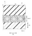
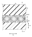
図1に示されるように、第1実施形態のタイヤ10は、内部に空気を充填して用いる空気入りタイヤであり、従来一般のゴム製の空気入りタイヤと略同様の断面形状を呈している。
図1に示されるように、第1実施形態のタイヤ10は、内部に空気を充填して用いる空気入りタイヤであり、従来一般のゴム製の空気入りタイヤと略同様の断面形状を呈している。
本実施形態のタイヤ10は、タイヤ10の骨格部分となるタイヤ骨格部材17を備えている。タイヤ骨格部材17は、骨格用樹脂材料を環状に形成したものである。このタイヤ骨格部材17は、タイヤ幅方向に間隔をあけて配置された一対のビード部12と、ビード部12のタイヤ径方向外側に連なるサイド部14と、サイド部14のタイヤ幅方向内側に連なり、各々のサイド部14のタイヤ径方向外側端同士を繋ぐクラウン部16と、を含んで構成されている。
なお、タイヤ骨格部材17の周方向、幅方向、径方向は、それぞれタイヤ周方向、タイヤ幅方向、タイヤ径方向に対応している。
なお、タイヤ骨格部材17の周方向、幅方向、径方向は、それぞれタイヤ周方向、タイヤ幅方向、タイヤ径方向に対応している。
タイヤ骨格部材17は、骨格用樹脂材料を主原料として形成されている。この骨格用樹脂材料には、加硫ゴムは含まれない。骨格用樹脂材料としては、熱可塑性樹脂(熱可塑性エラストマーを含む)、熱硬化性樹脂、及びその他の汎用樹脂のほか、エンジニアリングプラスチック(スーパーエンジニアリングプラスチックを含む)等が挙げられる。
熱可塑性樹脂(熱可塑性エラストマーを含む)とは、温度上昇と共に材料が軟化、流動し、冷却すると比較的硬く強度のある状態になる高分子化合物をいう。本明細書では、このうち、温度上昇と共に材料が軟化、流動し、冷却すると比較的硬く強度のある状態になり、かつ、ゴム状弾性を有する高分子化合物を熱可塑性エラストマーとし、温度上昇と共に材料が軟化、流動し、冷却すると比較的硬く強度のある状態になり、かつ、ゴム状弾性を有しない高分子化合物をエラストマーでない熱可塑性樹脂として、区別する。
熱可塑性樹脂(熱可塑性エラストマーを含む)としては、ポリオレフィン系熱可塑性エラストマー(TPO)、ポリスチレン系熱可塑性エラストマー(TPS)、ポリアミド系熱可塑性エラストマー(TPA)、ポリウレタン系熱可塑性エラストマー(TPU)、ポリエステル系熱可塑性エラストマー(TPC)、及び、動的架橋型熱可塑性エラストマー(TPV)、ならびに、ポリオレフィン系熱可塑性樹脂、ポリスチレン系熱可塑性樹脂、ポリアミド系熱可塑性樹脂、及び、ポリエステル系熱可塑性樹脂等が挙げられる。
また、上記の熱可塑性材料としては、例えば、ISO75-2又はASTM D648に規定されている荷重たわみ温度(0.45MPa荷重時)が78℃以上、JIS K7161に規定される引張降伏強さが10MPa以上、同じくJIS K7161に規定される引張破壊伸びが50%以上。JIS K7206に規定されるビカット軟化温度(A法)が130℃であるものを用いることができる。
熱硬化性樹脂とは、温度上昇と共に3次元的網目構造を形成し、硬化する高分子化合物をいう。熱硬化性樹脂としては、例えば、フェノール樹脂、エポキシ樹脂、メラミン樹脂、ユリア樹脂等が挙げられる。
なお、骨格用樹脂材料には、既述の熱可塑性樹脂(熱可塑性エラストマーを含む)及び熱硬化性樹脂のほか、(メタ)アクリル系樹脂、EVA樹脂、塩化ビニル樹脂、フッ素系樹脂、シリコーン系樹脂等の汎用樹脂を用いてもよい。
なお、タイヤ骨格部材17は、単一の骨格用樹脂材料で形成されても、タイヤ骨格部材17の各部位(ビード部12、サイド部14、クラウン部16など)毎に異なる特徴を有する骨格用樹脂材料で形成されてもよい。また、本実施形態では、タイヤ骨格部材17を熱可塑性樹脂で形成している。
図1に示されるように、ビード部12は、被覆ゴム24を介して標準リム(図示省略)に嵌合する部位であり、内部にタイヤ周方向に沿って延びる環状のビードコア18が埋設されている。ビードコア18は、金属コード(例えば、スチールコード)、有機繊維コード、樹脂被覆した有機繊維コード、または硬質樹脂などのビードコード(不図示)で構成されている。なお、ビードコア18に関しては、ビード部12の剛性を十分に確保できれば省略してもよい。
サイド部14は、タイヤ10の側部を構成する部位であり、ビード部12からクラウン部16に向ってタイヤ幅方向外側に凸となるように緩やかに湾曲している。
クラウン部16は、タイヤ径方向外側に配設される後述するトレッド30を支持する部位であり、外周面がタイヤ幅方向に沿って略平坦状とされている。
クラウン部16のタイヤ径方向外側には、ベルト層28が配設されている。このベルト層28は、被覆コード部材26をタイヤ周方向に螺旋状に巻回して形成されている。なお、被覆コード部材26の詳細については後述する。
ベルト層28のタイヤ径方向外側には、トレッド30が配設されている。このトレッド30は、ベルト層28を覆っている。また、トレッド30には、路面との接地面にトレッドパターン(図示省略)が形成されている。
また、タイヤ骨格部材17には、サイド部14の外面からビード部12の内面に亘って被覆ゴム24が配設されている。この被覆ゴム24を構成するゴム材としては、タイヤ骨格部材17よりも耐候性及び標準リムとのシール性が高いゴム材を用いている。なお、本実施形態では、タイヤ骨格部材17の外面がすべてトレッド30と被覆ゴム24とによって覆われている。
次に被覆コード部材26について詳細に説明する。
図2に示されるように、被覆コード部材26は、タイヤ周方向に延びる補強コード32と、この補強コード32を被覆する被覆用樹脂層34と、補強コード32と被覆用樹脂層34との間に配置されて補強コード32と被覆用樹脂層34とを接合(接着)する接合用樹脂層36と、を備えている。
図2に示されるように、被覆コード部材26は、タイヤ周方向に延びる補強コード32と、この補強コード32を被覆する被覆用樹脂層34と、補強コード32と被覆用樹脂層34との間に配置されて補強コード32と被覆用樹脂層34とを接合(接着)する接合用樹脂層36と、を備えている。
補強コード32は、金属繊維や有機繊維等のモノフィラメント(単線)又はこれらの繊維を撚ったマルチフィラメント(撚り線)で構成されている。なお、本実施形態では、補強コード32を金属繊維をよった金属コードとしている。
被覆用樹脂層34は、被覆用樹脂材料で形成されている。この被覆用樹脂材料としては、タイヤ骨格部材17を形成する骨格用樹脂材料と同様のものを用いることができる。なお、本実施形態では、被覆用樹脂材料として、熱可塑性樹脂を用いており、被覆用樹脂層34がクラウン部16に熱溶着によって接合されている。
また、本実施形態では、被覆用樹脂層34とクラウン部16を熱溶着で接合するため、被覆用樹脂材料と骨格用樹脂材料を同じ樹脂材料とすることが接合強度の観点から好ましい。なお、本発明はこの構成に限定されず、被覆用樹脂材料と骨格用樹脂材料を異なる樹脂材料としてもよい。
また、被覆用樹脂層34は、断面形状が略四角形状とされている。なお、被覆用樹脂層34の断面形状は略四角形状に限定されない。例えば、断面円形状や、断面台形状であっても構わない。
接合用樹脂層36は、被覆用樹脂材料よりも弾性率が高く、補強コード32との接着性に優れる接合用樹脂材料で形成されている。なお、ここでいう「弾性率」とは、JIS K7161に規定される引張弾性率を指す。また、接合用樹脂層36の弾性率は、被覆用樹脂層34の弾性率の1~5倍に設定することが好ましい。
接合用樹脂材料としては、例えば、変性オレフィン系樹脂(変性ポリエチレン系樹脂、変性ポリプロピレン系樹脂等)、ポリアミド系樹脂、ポリウレタン系樹脂、ポリエステル系樹脂、エチレン-アクリル酸エチル共重合体、エチレン-酢酸ビニル共重合体等の1種又は2種以上の熱可塑性樹脂を主成分(主剤)として含むものが挙げられる。これらの中でも、上記補強金属コード部材及び上記被覆用組成物との接着性の観点から、変性オレフィン系樹脂、ポリエステル系樹脂、エチレン-アクリル酸エチル共重合体、及びエチレン-酢酸ビニル共重合体から選ばれる少なくとも1種を含むホットメルト接着剤が好ましく、不飽和カルボン酸で酸変性された変性オレフィン系樹脂(酸変性オレフィン系樹脂)が更に好ましい。
ここで、「不飽和カルボン酸で酸変性された変性オレフィン系樹脂」とは、ポリオレフィンに、不飽和カルボン酸をグラフト共重合させた変性オレフィン系樹脂を意味する。
また、これらのオレフィン系熱可塑性エラストマーとしては、弾性率が140MPa~950MPaのものを用いることが好ましい。
ここで、「不飽和カルボン酸で酸変性された変性オレフィン系樹脂」とは、ポリオレフィンに、不飽和カルボン酸をグラフト共重合させた変性オレフィン系樹脂を意味する。
また、これらのオレフィン系熱可塑性エラストマーとしては、弾性率が140MPa~950MPaのものを用いることが好ましい。
接合用樹脂層36の層厚T1は、被覆用樹脂層34の層厚T2よりも厚く(大きく)されている。なお、ここでいう「層厚」は、補強コード32の中心から補強コード32の径方向に沿って測定した厚みの中で最も厚みの薄い部分を指す。
また、本実施形態では、接合用樹脂層36の層厚T1を500μm~5mmの範囲内に設定している。
図1及び図2に示されるように、被覆コード部材26は、クラウン部16の外周にタイヤ周方向に巻き付けられ且つ熱溶着によって接合されている。
また、被覆コード部材26は、クラウン部16の外周にタイヤ幅方向に隙間なく巻き付けられ、タイヤ幅方向に隣接する部分同士が熱溶着によって接合されている。なお、本発明は上記構成に限定されず、例えば、被覆コード部材26がタイヤ幅方向に隙間をあけて巻き付けられる構成としてもよい。
また、被覆コード部材26は、クラウン部16の外周にタイヤ幅方向に隙間なく巻き付けられ、タイヤ幅方向に隣接する部分同士が熱溶着によって接合されている。なお、本発明は上記構成に限定されず、例えば、被覆コード部材26がタイヤ幅方向に隙間をあけて巻き付けられる構成としてもよい。
次に、本実施形態のタイヤ10の製造方法の一例を説明する。
まず、骨格形成工程について説明する。
骨格形成工程では、骨格用樹脂材料を射出成形してタイヤ骨格部材17を半分に分割したタイヤ骨格半体(図示省略)を一対形成する。なお、タイヤ骨格半体の射出成形は、あらかじめ形成したビードコア18を成形型内の所定位置に配置した状態で行われる。このため、成形されたタイヤ骨格半体のビード部12にはビードコア18が埋設されている。
骨格形成工程では、骨格用樹脂材料を射出成形してタイヤ骨格部材17を半分に分割したタイヤ骨格半体(図示省略)を一対形成する。なお、タイヤ骨格半体の射出成形は、あらかじめ形成したビードコア18を成形型内の所定位置に配置した状態で行われる。このため、成形されたタイヤ骨格半体のビード部12にはビードコア18が埋設されている。
次に、一対のタイヤ骨格半体同士を熱溶着により接合してタイヤ骨格部材17を形成する。
その後、被覆ゴム24となる未加硫被覆ゴムをタイヤ骨格部材17のサイド部14の外面からビード部12の内面に亘って貼り付ける。これにより、未加硫被覆ゴム付きのタイヤ骨格部材17が形成される。
なお、本実施形態では、タイヤ骨格半体を一対形成し、一対のタイヤ骨格半体同士を接合することでタイヤ骨格部材を形成しているが、本発明はこの構成に限定されない。例えば、タイヤ骨格部材17を3以上の部位に分割して形成し、分割した部位同士を接合してタイヤ骨格部材17を形成してもよい。また、タイヤ骨格部材17を分割せずに形成してもよい。
次に、被覆コード部材成形工程について説明する。
被覆コード部材成形工程では、まず、補強コード32を溶融状態の接着用樹脂材料で被覆し、接着用樹脂材料が固化する前に溶融状態の被覆用樹脂材料で被覆する。そして、接着用樹脂材料及び被覆用樹脂材料が冷却固化されると、補強コード32の外周に接合用樹脂層36と被覆用樹脂層34とがそれぞれ形成されて被覆コード部材26が形成される。
なお、被覆コード部材成形工程は、上記構成に限定されず、補強コード32を被覆した接着用樹脂材料が冷却固化された後で、溶融状態の被覆用樹脂材料で被覆する構成としてもよい。
被覆コード部材成形工程では、まず、補強コード32を溶融状態の接着用樹脂材料で被覆し、接着用樹脂材料が固化する前に溶融状態の被覆用樹脂材料で被覆する。そして、接着用樹脂材料及び被覆用樹脂材料が冷却固化されると、補強コード32の外周に接合用樹脂層36と被覆用樹脂層34とがそれぞれ形成されて被覆コード部材26が形成される。
なお、被覆コード部材成形工程は、上記構成に限定されず、補強コード32を被覆した接着用樹脂材料が冷却固化された後で、溶融状態の被覆用樹脂材料で被覆する構成としてもよい。
被覆用樹脂層34及び接合用樹脂層36のそれぞれの形状は、図示しない押出機の押出口の形状を変更することで変えることができる。また、被覆用樹脂層34及び接合用樹脂層36のそれぞれの層厚についても同様に、押出機の押出口の開き量を変更することで調整することができる。
本実施形態では、図示しない押出機の押出口の開き量を変更して、接合用樹脂層36の層厚T1が被覆用樹脂層34の層厚T2よりも厚く(大きく)なるようにしている。
本実施形態では、図示しない押出機の押出口の開き量を変更して、接合用樹脂層36の層厚T1が被覆用樹脂層34の層厚T2よりも厚く(大きく)なるようにしている。
次に、ベルト成形工程について説明する。このベルト成形工程では、タイヤ骨格部材17の外周にベルト層28を形成する。具体的には、タイヤ骨格部材17のクラウン部16に被覆コード部材26を螺旋状に巻き付けてベルト層28を形成する。ここで、補強コード32は、被覆用樹脂層34のクラウン部16の外面と接触する部分を溶融させながらクラウン部16に巻き付けられるため、被覆用樹脂材料の冷却固化後には、クラウン部16に熱溶着によって強固に接合される。
次に、トレッド配置工程について説明する。このトレッド配置工程では、トレッド30となる未加硫トレッドゴム(図示省略)をベルト層28のタイヤ径方向外側に配置する。具体的には、タイヤ一周分の帯状の未加硫ゴムトレッドを、タイヤ骨格部材17の外周に巻き付けると共にベルト層28及びタイヤ骨格部材17の各々の外周面に接着剤を用いて接着する。
次に、加硫工程について説明する。この加硫工程では、タイヤ骨格部材17に接着された未加硫トレッドゴム及び未加硫被覆ゴムを加硫する。具体的には、タイヤ骨格部材17を加硫装置にセットして、未加硫トレッドゴム及び未加硫被覆ゴムを所定温度で所定時間加熱して加硫する。これにより、未加硫被覆ゴム及び未加硫トレッドが加硫されて最終製品の加硫度に至る。
次に、加硫済みのタイヤ10を加硫装置から取り出す。これにより、タイヤ10が完成する。
なお、本実施形態に係るタイヤの製造方法での各工程の順序は、適宜変更することが可能である。例えば、タイヤ骨格部材17に未加硫被覆ゴムを貼り付ける前に、タイヤ骨格部材17のクラウン部16上にベルト層28を配置し、ベルト層28上に未加硫のトレッド30を配置してもよい。また、一対のタイヤ半体同士を接合する前に、タイヤ半体に未加硫被覆ゴムを貼り付ける構成としてもよい。
次に、本実施形態のタイヤ10の作用効果について説明する。
タイヤ10では、接合用樹脂層36の層厚T1を被覆用樹脂層34の層厚T2よりも厚くしていることから、例えば、層厚T1を層厚T2以下とした場合と比べて、接合用樹脂層36が硬くなる。これにより、例えば、トレッド30に生じた外傷が被覆用樹脂層34に到達し、その結果被覆用樹脂層34に傷が生じても、この傷の進行速度が接合用樹脂層36で抑制される。具体的には、接合用樹脂層36は、被覆用樹脂材料よりも弾性率が高い接合用樹脂材料で形成されているため、被覆用樹脂層34よりも傷の進行速度を遅くできる。このため、接合用樹脂層36の層厚T1を被覆用樹脂層34の層厚T2よりも厚くすることで、被覆用樹脂層34に生じた傷が補強コード32に到達するまでの進行速度を抑制することができる。
タイヤ10では、接合用樹脂層36の層厚T1を被覆用樹脂層34の層厚T2よりも厚くしていることから、例えば、層厚T1を層厚T2以下とした場合と比べて、接合用樹脂層36が硬くなる。これにより、例えば、トレッド30に生じた外傷が被覆用樹脂層34に到達し、その結果被覆用樹脂層34に傷が生じても、この傷の進行速度が接合用樹脂層36で抑制される。具体的には、接合用樹脂層36は、被覆用樹脂材料よりも弾性率が高い接合用樹脂材料で形成されているため、被覆用樹脂層34よりも傷の進行速度を遅くできる。このため、接合用樹脂層36の層厚T1を被覆用樹脂層34の層厚T2よりも厚くすることで、被覆用樹脂層34に生じた傷が補強コード32に到達するまでの進行速度を抑制することができる。
一方、被覆用樹脂材料の弾性率を接合用樹脂材料の弾性率よりも低くしていることから、金属コードである補強コード32からクラウン部16までの弾性率差(剛性段差)を緩和できるため、補強コード32と被覆用樹脂層34との間に剥離などが生じるのを抑制できる。
さらにタイヤ10では、接合用樹脂層36の層厚T1を500μm~5mmの範囲内に設定していることから、接合用樹脂層36がさらに硬くなる。これにより、接合用樹脂層36における傷の進行速度をさらに抑制する(遅くする)ことができる。なお、層厚T1を500μm未満にした場合、接合用樹脂層36の層厚が足りず、接合用樹脂層36における傷の進行速度を抑制する効果が十分に確保できない虞がある。一方、層厚T1を5mm以上とした場合には、接合用樹脂層36が硬くなりすぎて補強コード32と被覆用樹脂層34との間に剥離が生じやすくなる虞がある。したがって、接合用樹脂層36の層厚T1は、500μm~5mmの範囲内に設定することが好ましい。
また、被覆コード部材26をタイヤ骨格部材17のクラウン部16の外周に螺旋状に巻回していることから、クラウン部16のタイヤ周方向剛性が向上する。また、被覆コード部材26によって形成されるベルト層28のたが効果によって、タイヤ転動時におけるクラウン部16の径成長(クラウン部16が径方向に膨らむ現象)が抑制される。
またさらに、タイヤ10では、被覆コード部材26の被覆用樹脂層34とタイヤ骨格部材17のクラウン部16を熱溶着によって接合していることから、被覆用樹脂層34とクラウン部16の接合強度が向上する。これにより、クラウン部16のタイヤ周方向剛性がさらに向上する。
第1実施形態のタイヤ10では、1本の被覆コード部材26をクラウン部16の外周にタイヤ周方向に螺旋状に巻回すると共に接合する構成としているが、本発明はこの構成に限定されず、複数の被覆コード部材26を並列させて帯状とした帯状体をクラウン部16の外周にタイヤ周方向に螺旋状に巻回と共に接合する構成としてもよい。
また、第1実施形態では、クラウン部16の外周面をタイヤ幅方向断面において平坦状にしているが、本発明はこの構成に限定されず、上記外周面をタイヤ幅方向断面において平坦状にしなくてもよい。例えば、クラウン部16の外周面をタイヤ幅方向断面においてタイヤ径方向外側へ膨らませた湾曲形状(円弧形状)にしてもよい。
第1実施形態のタイヤ10の製造方法では、被覆コード部材26の被覆用樹脂層34を溶融状態にしてクラウン部16と被覆コード部材26とを熱溶着で接合する構成としているが、本発明はこの構成に限定されない。例えば、クラウン部16の外周面を溶融状態にしてクラウン部16と被覆コード部材26とを熱溶着で接合する構成としてもよく、被覆コード部材26の被覆用樹脂層34とクラウン部16の外周面をそれぞれ溶融状態にしてクラウン部16と被覆コード部材26とを熱溶着で接合する構成としてもよい。
<第2実施形態>
次に、図3を用いて本発明の第2実施形態のタイヤについて説明する。なお、第1実施形態と同様の構成については同じ符号を付し、説明を適宜省略する。
次に、図3を用いて本発明の第2実施形態のタイヤについて説明する。なお、第1実施形態と同様の構成については同じ符号を付し、説明を適宜省略する。
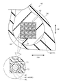
図3に示されるように、タイヤ40は、被覆コード部材44を巻回してビードコア42を構成している点を除いて、第1実施形態のタイヤ10と同一の構成である。
ビードコア42は、1本の被覆コード部材44を複数行複数列(本実施形態では4行4列)となるようにタイヤ周方向に巻回しながら並べて形成されている。
被覆コード部材44は、タイヤ周方向に延びる補強コード46と、この補強コード46を被覆する被覆用樹脂層48と、補強コード46と被覆用樹脂層48との間に配置されて補強コード46と被覆用樹脂層48とを接合(接着)する接合用樹脂層50と、を備えている。なお、本実施形態の補強コード46を構成する材料としては、第1実施形態の補強コード32を構成する材料と同様の材料を用いてもよく、本実施形態の被覆用樹脂層48を構成する被覆用樹脂材料としては、被覆用樹脂層34を構成する被覆用樹脂材料と同様の材料を用いてもよく、本実施形態の接合用樹脂層50を構成する接合用樹脂材料としては、接合用樹脂層36を構成する接合用樹脂材料と同様の材料を用いてもよい。
また、接合用樹脂層50の層厚T1は、被覆用樹脂層48の層厚T2よりも厚くされている。
また、接合用樹脂層50の層厚T1は、被覆用樹脂層48の層厚T2よりも厚くされている。
また、被覆コード部材44は、タイヤ幅方向及びタイヤ径方向の少なくとも一方に隣接する部分同士が熱溶着によって接合されている。また、ビードコア42の外周部を構成する被覆コード部材44の被覆用樹脂層48がビード部12に熱溶着によって接合されている。具体的には、骨格成形工程において、予め形成されたビードコア42が成形型内に配置された状態で射出成形が行われるため、成形型内で骨格用樹脂材料とビードコア42の外周部を構成する被覆用樹脂層48が熱溶着によって接合される。
次に、本実施形態のタイヤ40の作用効果について説明する。なお、第1実施形態のタイヤ10と同様の構成で得られる作用効果については説明を省略する。
タイヤ40では、接合用樹脂層50の層厚T1を被覆用樹脂層48の層厚T2よりも厚くしていることから、例えば、層厚T1を層厚T2以下とした場合と比べて、接合用樹脂層50が硬くなる。これにより、例えば、被覆ゴム24に生じた外傷が被覆用樹脂層48に到達し、その結果被覆用樹脂層48に傷が生じても、この傷の進行速度が接合用樹脂層50で抑制される。具体的には、接合用樹脂層50は、被覆用樹脂材料よりも弾性率が高い接合用樹脂材料で形成されているため、被覆用樹脂層48よりも傷の進行速度を遅くできる。このため、接合用樹脂層50の層厚T1を被覆用樹脂層48の層厚T2よりも厚くすることで、被覆用樹脂層48に生じた傷が補強コード46に到達するまでの進行速度を抑制することができる。
一方、被覆用樹脂材料の弾性率を接合用樹脂材料の弾性率よりも低くしていることから、金属コードである補強コード46からビード部12までの弾性率差(剛性段差)を緩和できるため、補強コード46と被覆用樹脂層48との間に剥離などが生じるのを抑制できる。
さらにタイヤ40では、接合用樹脂層50の層厚T1を500μm~5mmの範囲内に設定していることから、接合用樹脂層50がさらに硬くなる。これにより、接合用樹脂層50における傷の進行速度をさらに抑制する(遅くする)ことができる。なお、層厚T1を500μm未満にした場合、接合用樹脂層50の層厚が足りず、接合用樹脂層50における傷の進行速度を抑制する効果が十分に確保できない虞がある。一方、層厚T1を5mm以上とした場合には、接合用樹脂層50が硬くなりすぎて補強コード46と被覆用樹脂層48との間に剥離が生じやすくなる虞がある。したがって、接合用樹脂層50の層厚T1は、500μm~5mmの範囲内に設定することが好ましい。
またタイヤ40では、被覆コード部材44で形成したビードコア42をビード部12内に埋設すると共に熱溶着によって接合していることから、タイヤ骨格部材17のビード部12の周方向剛性が向上する。
またさらに、タイヤ40では、被覆コード部材44の被覆用樹脂層48とタイヤ骨格部材17のビード部12とを熱溶着によって接合していることから、被覆用樹脂層48とビード部12との接合強度が向上する。これにより、ビード部12のタイヤ周方向剛性がさらに向上する。
第2実施形態のタイヤ40では、では、1本の被覆コード部材44を複数行複数列となるようにタイヤ周方向に巻回してビードコア42を構成としているが、本発明はこの構成に限定されず、複数の被覆コード部材44を並列させて帯状とした帯状体をタイヤ周方向に複数回巻回してビードコア42を形成してもよい。
また第2実施形態のタイヤ40では、被覆コード部材26でベルト層28を形成し、被覆コード部材44でビードコア42を形成しているが、本発明はこの構成に限定されない。その他の実施形態としては、被覆コード部材44でビードコア42を形成しつつ、ゴム被覆した補強コードでベルト層を形成する、または、未被覆の補強コードをクラウン部16の外周に埋設(一部埋設を含む)しながら巻回してベルト層を形成する構成としてもよい。
第1実施形態では、被覆コード部材26の被覆用樹脂層34を単一の被覆用樹脂材料で構成しているが、本発明はこの構成に限定されない。例えば、被覆コード部材26の被覆用樹脂層34を弾性率の異なる複数の被覆用樹脂材料で構成してもよい。具体的には、図4に示される被覆コード部材60のように、被覆用樹脂層62を多層とし、被覆用樹脂層62の各層を弾性率の異なる被覆用樹脂材料で形成する。ここで、被覆用樹脂層62を構成する内側の樹脂層64よりも外側の樹脂層66の弾性率を低くすることで、弾性率差による層間剥離を抑制することができる。この結果、タイヤの耐久性が向上する。なお、上記被覆コード部材60の被覆用樹脂層62を多層とする構成については、第2実施形態の被覆コード部材44の被覆用樹脂層48に適用してもよい。
また、第1実施形態では、図2に示されるように被覆コード部材26の接合用樹脂層36を断面円形状とし、その外周を断面四角形状の被覆用樹脂層34で被覆する構成としているが、本発明はこの構成に限定されない。例えば、図5に示される被覆コード部材70のように、接合用樹脂層72を断面四角形状とし、その外周を断面四角形状の被覆用樹脂層74で被覆する構成としてもよい。なお、上記被覆コード部材70の接合用樹脂層72及び被覆用樹脂層74のそれぞれの断面形状を四角形状とする構成については、第2実施形態の被覆コード部材44の被覆用樹脂層48に適用してもよい。
以上、実施形態を挙げて本発明の実施の形態を説明したが、これらの実施形態は一例であり、要旨を逸脱しない範囲内で種々変更して実施でき、製造工程の順序を適宜変更することが可能である。また、本発明の権利範囲がこれらの実施形態に限定されないことは言うまでもない。
なお、2014年11月26日に出願された日本国特許出願2014-239281号の開示は、その全体が参照により本明細書に取り込まれる。
本明細書に記載された全ての文献、特許出願、および技術規格は、個々の文献、特許出願、および技術規格が参照により取り込まれることが具体的かつ個々に記された場合と同程度に、本明細書中に参照により取り込まれる。
本明細書に記載された全ての文献、特許出願、および技術規格は、個々の文献、特許出願、および技術規格が参照により取り込まれることが具体的かつ個々に記された場合と同程度に、本明細書中に参照により取り込まれる。
Claims (6)
- 骨格用樹脂材料で形成された環状のタイヤ骨格部材と、
前記タイヤ骨格部材に設けられ、タイヤ周方向に延びる補強コードと、被覆用樹脂材料で形成され、前記補強コードを被覆すると共に前記タイヤ骨格部材に接合された被覆用樹脂層と、前記被覆用樹脂材料よりも弾性率が高い接合用樹脂材料で形成され、前記補強コードと前記被覆用樹脂層との間に配置されて前記補強コードと前記被覆用樹脂層とを接合し、層厚が前記被覆用樹脂層よりも厚い接合用樹脂層と、を備える被覆コード部材と、
を有するタイヤ。 - 前記タイヤ骨格部材は、ビード部と、前記ビード部のタイヤ径方向外側に連なるサイド部と、前記サイド部のタイヤ幅方向内側に連なるクラウン部と、を備え、
前記被覆コード部材は、前記クラウン部の外周に螺旋状に巻回されている、請求項1に記載のタイヤ。 - 前記被覆用樹脂材料は、熱可塑性を有し、
前記被覆用樹脂層と前記クラウン部とが熱溶着によって接合されている、請求項2に記載のタイヤ。 - 前記タイヤ骨格部材は、ビード部と、前記ビード部のタイヤ径方向外側に連なるサイド部と、前記サイド部のタイヤ幅方向内側に連なるクラウン部と、を備え、
前記被覆コード部材は、前記ビード部内に埋設されている、請求項1に記載のタイヤ。 - 前記骨格用樹脂材料は、熱可塑性を有し、
前記被覆用樹脂層と前記ビード部とが熱溶着によって接合されている、請求項4に記載のタイヤ。 - 前記接合用樹脂層の層厚が500μm~5mmである、請求項1~5のいずれか1項に記載のタイヤ。
Priority Applications (3)
| Application Number | Priority Date | Filing Date | Title |
|---|---|---|---|
| CN201580064721.1A CN107000480B (zh) | 2014-11-26 | 2015-10-26 | 轮胎 |
| US15/529,523 US20170305197A1 (en) | 2014-11-26 | 2015-10-26 | Tire |
| EP15863900.5A EP3225425B1 (en) | 2014-11-26 | 2015-10-26 | Tire |
Applications Claiming Priority (2)
| Application Number | Priority Date | Filing Date | Title |
|---|---|---|---|
| JP2014-239281 | 2014-11-26 | ||
| JP2014239281A JP6266498B2 (ja) | 2014-11-26 | 2014-11-26 | タイヤ |
Publications (1)
| Publication Number | Publication Date |
|---|---|
| WO2016084536A1 true WO2016084536A1 (ja) | 2016-06-02 |
Family
ID=56074111
Family Applications (1)
| Application Number | Title | Priority Date | Filing Date |
|---|---|---|---|
| PCT/JP2015/080146 WO2016084536A1 (ja) | 2014-11-26 | 2015-10-26 | タイヤ |
Country Status (5)
| Country | Link |
|---|---|
| US (1) | US20170305197A1 (ja) |
| EP (1) | EP3225425B1 (ja) |
| JP (1) | JP6266498B2 (ja) |
| CN (1) | CN107000480B (ja) |
| WO (1) | WO2016084536A1 (ja) |
Cited By (3)
| Publication number | Priority date | Publication date | Assignee | Title |
|---|---|---|---|---|
| WO2018230146A1 (ja) * | 2017-06-14 | 2018-12-20 | 株式会社ブリヂストン | 吸音部材付き空気入りタイヤ、及びタイヤ・リム組立体 |
| WO2020085497A1 (ja) * | 2018-10-26 | 2020-04-30 | 株式会社ブリヂストン | タイヤ |
| EP3608128A4 (en) * | 2017-04-06 | 2020-11-25 | Bridgestone Corporation | RESIN-METAL COMPOSITE ELEMENT FOR PNEUMATICS AND PNEUMATICS |
Families Citing this family (19)
| Publication number | Priority date | Publication date | Assignee | Title |
|---|---|---|---|---|
| JP2018079899A (ja) * | 2016-11-18 | 2018-05-24 | 株式会社ブリヂストン | タイヤ |
| JP6786438B2 (ja) * | 2017-05-10 | 2020-11-18 | 株式会社ブリヂストン | 空気入りタイヤ |
| JP6845086B2 (ja) * | 2017-05-24 | 2021-03-17 | 株式会社ブリヂストン | 空気入りタイヤ |
| CN110603159B (zh) * | 2017-05-10 | 2021-11-26 | 株式会社普利司通 | 充气轮胎 |
| JP2019001357A (ja) * | 2017-06-16 | 2019-01-10 | 株式会社ブリヂストン | タイヤ用樹脂金属複合部材、及びタイヤ |
| JP6781671B2 (ja) * | 2017-06-19 | 2020-11-04 | 株式会社ブリヂストン | ランフラットタイヤ |
| WO2019070084A1 (ja) * | 2017-10-06 | 2019-04-11 | 株式会社ブリヂストン | タイヤ用ビード部材、タイヤ、及びタイヤ用ビード部材の製造方法 |
| CN111194272A (zh) * | 2017-10-06 | 2020-05-22 | 株式会社普利司通 | 轮胎用胎圈构件、轮胎以及轮胎用胎圈构件的制造方法 |
| JP6857596B2 (ja) | 2017-12-08 | 2021-04-14 | 株式会社ブリヂストン | タイヤ |
| JP6989224B2 (ja) * | 2018-06-14 | 2022-01-05 | 株式会社ブリヂストン | ベルト層構成部材の製造方法 |
| JP2019217819A (ja) * | 2018-06-15 | 2019-12-26 | 株式会社ブリヂストン | 空気入りタイヤ |
| JP2019217871A (ja) * | 2018-06-19 | 2019-12-26 | 株式会社ブリヂストン | タイヤ |
| JP2019217957A (ja) * | 2018-06-21 | 2019-12-26 | 株式会社ブリヂストン | 空気入りタイヤ |
| JP6976908B2 (ja) * | 2018-06-22 | 2021-12-08 | 株式会社ブリヂストン | 樹脂被覆コード及び空気入りタイヤ |
| JP7331316B2 (ja) * | 2018-09-21 | 2023-08-23 | 株式会社ブリヂストン | タイヤ |
| JPWO2020067473A1 (ja) * | 2018-09-28 | 2021-08-30 | 株式会社ブリヂストン | タイヤ |
| JP2020055494A (ja) * | 2018-10-04 | 2020-04-09 | 株式会社ブリヂストン | タイヤ |
| JP2020062935A (ja) * | 2018-10-16 | 2020-04-23 | 株式会社ブリヂストン | タイヤ用ワイヤー樹脂複合部材、及びタイヤ |
| JP6943274B2 (ja) * | 2019-10-08 | 2021-09-29 | 住友ゴム工業株式会社 | 空気入りタイヤ |
Citations (6)
| Publication number | Priority date | Publication date | Assignee | Title |
|---|---|---|---|---|
| JP2006282102A (ja) * | 2005-04-04 | 2006-10-19 | Sumitomo Rubber Ind Ltd | 空気入りタイヤ |
| JP2010053495A (ja) * | 2008-08-29 | 2010-03-11 | Yokohama Rubber Co Ltd:The | タイヤ補強用スチールコード及びこれを使用した空気入りタイヤ |
| JP2011042235A (ja) * | 2009-08-20 | 2011-03-03 | Bridgestone Corp | タイヤ、及びタイヤの製造方法。 |
| WO2013089111A1 (ja) * | 2011-12-12 | 2013-06-20 | 株式会社ブリヂストン | タイヤ |
| JP2013180652A (ja) * | 2012-03-01 | 2013-09-12 | Bridgestone Corp | タイヤ |
| WO2014175453A1 (ja) * | 2013-04-25 | 2014-10-30 | 株式会社ブリヂストン | タイヤ |
Family Cites Families (9)
| Publication number | Priority date | Publication date | Assignee | Title |
|---|---|---|---|---|
| US5127456A (en) * | 1985-01-18 | 1992-07-07 | Compagnie Generale Des Etablissements Michelin | Sheathed bead ring to pneumatic tires; method of producing such a bead ring; pneumatic tires having such a bead ring |
| FR2576247B1 (fr) * | 1985-01-18 | 1987-07-31 | Michelin & Cie | Ensembles renforcants comportant des fils de renfort et une matrice; procede pour obtenir ces ensembles; articles comportant ces ensembles |
| JPH1053981A (ja) * | 1996-08-06 | 1998-02-24 | Sumitomo Rubber Ind Ltd | タイヤ用のスチールコード及びそれを用いた空気入りタイヤ |
| FR2943269B1 (fr) * | 2009-03-20 | 2011-04-22 | Michelin Soc Tech | Renfort composite auto-adherent |
| FR2945826B1 (fr) * | 2009-05-25 | 2011-12-02 | Michelin Soc Tech | Renfort composite auto-adherent |
| CN102548774B (zh) * | 2009-08-20 | 2015-12-09 | 株式会社普利司通 | 轮胎及轮胎的制造方法 |
| JP5436303B2 (ja) * | 2010-03-30 | 2014-03-05 | 株式会社ブリヂストン | タイヤ、及び、タイヤの製造方法 |
| US9649819B2 (en) * | 2010-03-30 | 2017-05-16 | Bridgestone Corporation | Tire manufacturing method using jig to fix covered bead inside tire mold |
| EP2990221B1 (en) * | 2013-04-25 | 2017-04-05 | Bridgestone Corporation | Tire |
-
2014
- 2014-11-26 JP JP2014239281A patent/JP6266498B2/ja active Active
-
2015
- 2015-10-26 US US15/529,523 patent/US20170305197A1/en not_active Abandoned
- 2015-10-26 EP EP15863900.5A patent/EP3225425B1/en not_active Not-in-force
- 2015-10-26 WO PCT/JP2015/080146 patent/WO2016084536A1/ja active Application Filing
- 2015-10-26 CN CN201580064721.1A patent/CN107000480B/zh not_active Expired - Fee Related
Patent Citations (6)
| Publication number | Priority date | Publication date | Assignee | Title |
|---|---|---|---|---|
| JP2006282102A (ja) * | 2005-04-04 | 2006-10-19 | Sumitomo Rubber Ind Ltd | 空気入りタイヤ |
| JP2010053495A (ja) * | 2008-08-29 | 2010-03-11 | Yokohama Rubber Co Ltd:The | タイヤ補強用スチールコード及びこれを使用した空気入りタイヤ |
| JP2011042235A (ja) * | 2009-08-20 | 2011-03-03 | Bridgestone Corp | タイヤ、及びタイヤの製造方法。 |
| WO2013089111A1 (ja) * | 2011-12-12 | 2013-06-20 | 株式会社ブリヂストン | タイヤ |
| JP2013180652A (ja) * | 2012-03-01 | 2013-09-12 | Bridgestone Corp | タイヤ |
| WO2014175453A1 (ja) * | 2013-04-25 | 2014-10-30 | 株式会社ブリヂストン | タイヤ |
Non-Patent Citations (1)
| Title |
|---|
| See also references of EP3225425A4 * |
Cited By (4)
| Publication number | Priority date | Publication date | Assignee | Title |
|---|---|---|---|---|
| EP3608128A4 (en) * | 2017-04-06 | 2020-11-25 | Bridgestone Corporation | RESIN-METAL COMPOSITE ELEMENT FOR PNEUMATICS AND PNEUMATICS |
| WO2018230146A1 (ja) * | 2017-06-14 | 2018-12-20 | 株式会社ブリヂストン | 吸音部材付き空気入りタイヤ、及びタイヤ・リム組立体 |
| JP2019001285A (ja) * | 2017-06-14 | 2019-01-10 | 株式会社ブリヂストン | 吸音部材付き空気入りタイヤ、及びタイヤ・リム組立体 |
| WO2020085497A1 (ja) * | 2018-10-26 | 2020-04-30 | 株式会社ブリヂストン | タイヤ |
Also Published As
| Publication number | Publication date |
|---|---|
| JP2016097945A (ja) | 2016-05-30 |
| CN107000480B (zh) | 2019-08-09 |
| CN107000480A (zh) | 2017-08-01 |
| EP3225425B1 (en) | 2019-03-20 |
| JP6266498B2 (ja) | 2018-01-24 |
| EP3225425A4 (en) | 2017-11-29 |
| EP3225425A1 (en) | 2017-10-04 |
| US20170305197A1 (en) | 2017-10-26 |
Similar Documents
| Publication | Publication Date | Title |
|---|---|---|
| JP6266498B2 (ja) | タイヤ | |
| WO2016084535A1 (ja) | タイヤ | |
| JP5993545B2 (ja) | タイヤ | |
| JP6622701B2 (ja) | タイヤ | |
| JP6517073B2 (ja) | タイヤ | |
| JP6534293B2 (ja) | タイヤ | |
| JP6204672B2 (ja) | タイヤ | |
| EP3459761A1 (en) | Tire | |
| US20190283504A1 (en) | Tire | |
| WO2018207617A1 (ja) | 空気入りタイヤ | |
| JP6408070B2 (ja) | タイヤ | |
| WO2016027893A1 (ja) | タイヤの製造方法及びタイヤ | |
| JP6873837B2 (ja) | ビードコアの製造方法 | |
| JP5619528B2 (ja) | タイヤ | |
| JP5901735B2 (ja) | タイヤ | |
| WO2019239896A1 (ja) | タイヤ及びベルト層構成部材の製造方法 | |
| WO2019244720A1 (ja) | タイヤ | |
| JP2021088789A (ja) | 繊維、樹脂被覆コードの製造方法、空気入りタイヤの製造方法 | |
| JP2015155304A (ja) | タイヤ |
Legal Events
| Date | Code | Title | Description |
|---|---|---|---|
| 121 | Ep: the epo has been informed by wipo that ep was designated in this application |
Ref document number: 15863900 Country of ref document: EP Kind code of ref document: A1 |
|
| WWE | Wipo information: entry into national phase |
Ref document number: 15529523 Country of ref document: US |
|
| NENP | Non-entry into the national phase |
Ref country code: DE |
|
| REEP | Request for entry into the european phase |
Ref document number: 2015863900 Country of ref document: EP |