WO2016084426A1 - 情報収集システム - Google Patents
情報収集システム Download PDFInfo
- Publication number
- WO2016084426A1 WO2016084426A1 PCT/JP2015/071952 JP2015071952W WO2016084426A1 WO 2016084426 A1 WO2016084426 A1 WO 2016084426A1 JP 2015071952 W JP2015071952 W JP 2015071952W WO 2016084426 A1 WO2016084426 A1 WO 2016084426A1
- Authority
- WO
- WIPO (PCT)
- Prior art keywords
- transmitter
- receiver
- collection system
- information
- information collection
- Prior art date
- Legal status (The legal status is an assumption and is not a legal conclusion. Google has not performed a legal analysis and makes no representation as to the accuracy of the status listed.)
- Ceased
Links
Images



Classifications
-
- G—PHYSICS
- G06—COMPUTING OR CALCULATING; COUNTING
- G06Q—INFORMATION AND COMMUNICATION TECHNOLOGY [ICT] SPECIALLY ADAPTED FOR ADMINISTRATIVE, COMMERCIAL, FINANCIAL, MANAGERIAL OR SUPERVISORY PURPOSES; SYSTEMS OR METHODS SPECIALLY ADAPTED FOR ADMINISTRATIVE, COMMERCIAL, FINANCIAL, MANAGERIAL OR SUPERVISORY PURPOSES, NOT OTHERWISE PROVIDED FOR
- G06Q30/00—Commerce
- G06Q30/02—Marketing; Price estimation or determination; Fundraising
- G06Q30/0201—Market modelling; Market analysis; Collecting market data
-
- G—PHYSICS
- G01—MEASURING; TESTING
- G01C—MEASURING DISTANCES, LEVELS OR BEARINGS; SURVEYING; NAVIGATION; GYROSCOPIC INSTRUMENTS; PHOTOGRAMMETRY OR VIDEOGRAMMETRY
- G01C22/00—Measuring distance traversed on the ground by vehicles, persons, animals or other moving solid bodies, e.g. using odometers, using pedometers
- G01C22/006—Pedometers
-
- G—PHYSICS
- G06—COMPUTING OR CALCULATING; COUNTING
- G06K—GRAPHICAL DATA READING; PRESENTATION OF DATA; RECORD CARRIERS; HANDLING RECORD CARRIERS
- G06K19/00—Record carriers for use with machines and with at least a part designed to carry digital markings
- G06K19/06—Record carriers for use with machines and with at least a part designed to carry digital markings characterised by the kind of the digital marking, e.g. shape, nature, code
- G06K19/067—Record carriers with conductive marks, printed circuits or semiconductor circuit elements, e.g. credit or identity cards also with resonating or responding marks without active components
- G06K19/07—Record carriers with conductive marks, printed circuits or semiconductor circuit elements, e.g. credit or identity cards also with resonating or responding marks without active components with integrated circuit chips
-
- G—PHYSICS
- G06—COMPUTING OR CALCULATING; COUNTING
- G06K—GRAPHICAL DATA READING; PRESENTATION OF DATA; RECORD CARRIERS; HANDLING RECORD CARRIERS
- G06K19/00—Record carriers for use with machines and with at least a part designed to carry digital markings
- G06K19/06—Record carriers for use with machines and with at least a part designed to carry digital markings characterised by the kind of the digital marking, e.g. shape, nature, code
- G06K19/067—Record carriers with conductive marks, printed circuits or semiconductor circuit elements, e.g. credit or identity cards also with resonating or responding marks without active components
- G06K19/07—Record carriers with conductive marks, printed circuits or semiconductor circuit elements, e.g. credit or identity cards also with resonating or responding marks without active components with integrated circuit chips
- G06K19/0701—Record carriers with conductive marks, printed circuits or semiconductor circuit elements, e.g. credit or identity cards also with resonating or responding marks without active components with integrated circuit chips at least one of the integrated circuit chips comprising an arrangement for power management
- G06K19/0707—Record carriers with conductive marks, printed circuits or semiconductor circuit elements, e.g. credit or identity cards also with resonating or responding marks without active components with integrated circuit chips at least one of the integrated circuit chips comprising an arrangement for power management the arrangement being capable of collecting energy from external energy sources, e.g. thermocouples, vibration, electromagnetic radiation
-
- G—PHYSICS
- G06—COMPUTING OR CALCULATING; COUNTING
- G06K—GRAPHICAL DATA READING; PRESENTATION OF DATA; RECORD CARRIERS; HANDLING RECORD CARRIERS
- G06K19/00—Record carriers for use with machines and with at least a part designed to carry digital markings
- G06K19/06—Record carriers for use with machines and with at least a part designed to carry digital markings characterised by the kind of the digital marking, e.g. shape, nature, code
- G06K19/067—Record carriers with conductive marks, printed circuits or semiconductor circuit elements, e.g. credit or identity cards also with resonating or responding marks without active components
- G06K19/07—Record carriers with conductive marks, printed circuits or semiconductor circuit elements, e.g. credit or identity cards also with resonating or responding marks without active components with integrated circuit chips
- G06K19/0716—Record carriers with conductive marks, printed circuits or semiconductor circuit elements, e.g. credit or identity cards also with resonating or responding marks without active components with integrated circuit chips at least one of the integrated circuit chips comprising a sensor or an interface to a sensor
-
- G—PHYSICS
- G06—COMPUTING OR CALCULATING; COUNTING
- G06K—GRAPHICAL DATA READING; PRESENTATION OF DATA; RECORD CARRIERS; HANDLING RECORD CARRIERS
- G06K19/00—Record carriers for use with machines and with at least a part designed to carry digital markings
- G06K19/06—Record carriers for use with machines and with at least a part designed to carry digital markings characterised by the kind of the digital marking, e.g. shape, nature, code
- G06K19/067—Record carriers with conductive marks, printed circuits or semiconductor circuit elements, e.g. credit or identity cards also with resonating or responding marks without active components
- G06K19/07—Record carriers with conductive marks, printed circuits or semiconductor circuit elements, e.g. credit or identity cards also with resonating or responding marks without active components with integrated circuit chips
- G06K19/0723—Record carriers with conductive marks, printed circuits or semiconductor circuit elements, e.g. credit or identity cards also with resonating or responding marks without active components with integrated circuit chips the record carrier comprising an arrangement for non-contact communication, e.g. wireless communication circuits on transponder cards, non-contact smart cards or RFIDs
-
- G—PHYSICS
- G06—COMPUTING OR CALCULATING; COUNTING
- G06K—GRAPHICAL DATA READING; PRESENTATION OF DATA; RECORD CARRIERS; HANDLING RECORD CARRIERS
- G06K7/00—Methods or arrangements for sensing record carriers, e.g. for reading patterns
- G06K7/10—Methods or arrangements for sensing record carriers, e.g. for reading patterns by electromagnetic radiation, e.g. optical sensing; by corpuscular radiation
-
- G—PHYSICS
- G06—COMPUTING OR CALCULATING; COUNTING
- G06K—GRAPHICAL DATA READING; PRESENTATION OF DATA; RECORD CARRIERS; HANDLING RECORD CARRIERS
- G06K7/00—Methods or arrangements for sensing record carriers, e.g. for reading patterns
- G06K7/10—Methods or arrangements for sensing record carriers, e.g. for reading patterns by electromagnetic radiation, e.g. optical sensing; by corpuscular radiation
- G06K7/10009—Methods or arrangements for sensing record carriers, e.g. for reading patterns by electromagnetic radiation, e.g. optical sensing; by corpuscular radiation sensing by radiation using wavelengths larger than 0.1 mm, e.g. radio-waves or microwaves
- G06K7/10366—Methods or arrangements for sensing record carriers, e.g. for reading patterns by electromagnetic radiation, e.g. optical sensing; by corpuscular radiation sensing by radiation using wavelengths larger than 0.1 mm, e.g. radio-waves or microwaves the interrogation device being adapted for miscellaneous applications
- G06K7/10415—Methods or arrangements for sensing record carriers, e.g. for reading patterns by electromagnetic radiation, e.g. optical sensing; by corpuscular radiation sensing by radiation using wavelengths larger than 0.1 mm, e.g. radio-waves or microwaves the interrogation device being adapted for miscellaneous applications the interrogation device being fixed in its position, such as an access control device for reading wireless access cards, or a wireless ATM
-
- G—PHYSICS
- G06—COMPUTING OR CALCULATING; COUNTING
- G06Q—INFORMATION AND COMMUNICATION TECHNOLOGY [ICT] SPECIALLY ADAPTED FOR ADMINISTRATIVE, COMMERCIAL, FINANCIAL, MANAGERIAL OR SUPERVISORY PURPOSES; SYSTEMS OR METHODS SPECIALLY ADAPTED FOR ADMINISTRATIVE, COMMERCIAL, FINANCIAL, MANAGERIAL OR SUPERVISORY PURPOSES, NOT OTHERWISE PROVIDED FOR
- G06Q10/00—Administration; Management
- G06Q10/08—Logistics, e.g. warehousing, loading or distribution; Inventory or stock management
- G06Q10/083—Shipping
- G06Q10/0833—Tracking
-
- G—PHYSICS
- G06—COMPUTING OR CALCULATING; COUNTING
- G06Q—INFORMATION AND COMMUNICATION TECHNOLOGY [ICT] SPECIALLY ADAPTED FOR ADMINISTRATIVE, COMMERCIAL, FINANCIAL, MANAGERIAL OR SUPERVISORY PURPOSES; SYSTEMS OR METHODS SPECIALLY ADAPTED FOR ADMINISTRATIVE, COMMERCIAL, FINANCIAL, MANAGERIAL OR SUPERVISORY PURPOSES, NOT OTHERWISE PROVIDED FOR
- G06Q10/00—Administration; Management
- G06Q10/08—Logistics, e.g. warehousing, loading or distribution; Inventory or stock management
- G06Q10/087—Inventory or stock management, e.g. order filling, procurement or balancing against orders
-
- G—PHYSICS
- G06—COMPUTING OR CALCULATING; COUNTING
- G06Q—INFORMATION AND COMMUNICATION TECHNOLOGY [ICT] SPECIALLY ADAPTED FOR ADMINISTRATIVE, COMMERCIAL, FINANCIAL, MANAGERIAL OR SUPERVISORY PURPOSES; SYSTEMS OR METHODS SPECIALLY ADAPTED FOR ADMINISTRATIVE, COMMERCIAL, FINANCIAL, MANAGERIAL OR SUPERVISORY PURPOSES, NOT OTHERWISE PROVIDED FOR
- G06Q20/00—Payment architectures, schemes or protocols
- G06Q20/08—Payment architectures
- G06Q20/20—Point-of-sale [POS] network systems
-
- A—HUMAN NECESSITIES
- A61—MEDICAL OR VETERINARY SCIENCE; HYGIENE
- A61B—DIAGNOSIS; SURGERY; IDENTIFICATION
- A61B5/00—Measuring for diagnostic purposes; Identification of persons
- A61B5/0002—Remote monitoring of patients using telemetry, e.g. transmission of vital signals via a communication network
-
- A—HUMAN NECESSITIES
- A61—MEDICAL OR VETERINARY SCIENCE; HYGIENE
- A61B—DIAGNOSIS; SURGERY; IDENTIFICATION
- A61B5/00—Measuring for diagnostic purposes; Identification of persons
- A61B5/103—Measuring devices for testing the shape, pattern, colour, size or movement of the body or parts thereof, for diagnostic purposes
- A61B5/11—Measuring movement of the entire body or parts thereof, e.g. head or hand tremor or mobility of a limb
- A61B5/1113—Local tracking of patients, e.g. in a hospital or private home
-
- A—HUMAN NECESSITIES
- A61—MEDICAL OR VETERINARY SCIENCE; HYGIENE
- A61B—DIAGNOSIS; SURGERY; IDENTIFICATION
- A61B5/00—Measuring for diagnostic purposes; Identification of persons
- A61B5/103—Measuring devices for testing the shape, pattern, colour, size or movement of the body or parts thereof, for diagnostic purposes
- A61B5/11—Measuring movement of the entire body or parts thereof, e.g. head or hand tremor or mobility of a limb
- A61B5/1116—Determining posture transitions
- A61B5/1117—Fall detection
Definitions
- the present invention relates to an information collection system.
- Patent Literature 1 and Patent Literature 2 the identification ID of an IC tag mounted in a shopping cart or a shopping basket is read by an IC tag reader provided in the store, and each identification ID of the IC tag and the IC tag reader and its ID An information collection system that collects location information of a purchaser in a store by managing the association with a reading time is disclosed.
- an object of the invention disclosed in this specification is to provide an information collection system using a self-supporting power source type transmitter.
- the information collection system disclosed in the present specification is a self-sustained power transmitter that is movable along with a moving body and spontaneously intermittently transmits a transmitter ID at a timing according to the amount of movement of the moving body.
- a plurality of receivers which are provided in a monitoring target area where the mobile body can freely move and receive transmitter IDs transmitted from transmitters existing in the vicinity thereof; and the transmitter IDs
- a server that manages the location information of the receiver that has received the transmitter ID and the reception time of the transmitter ID in association with each other (first configuration).
- the transmitter includes a power generation unit that converts kinetic energy into electrical energy, a power storage unit that stores the electrical energy generated by the power generation unit, and a power storage unit. It is good to make it the structure (2nd structure) including the transmission part which receives the supply and transmits said transmitter ID whenever the predetermined amount of electric energy is stored.
- the transmitter includes a rotation measuring unit that measures a caster rotation number, and a transmitter unit that transmits the transmitter ID every time the caster rotation number reaches a predetermined value. And (3rd configuration).
- the transmitter includes a step counting unit that measures the number of steps, and a transmitter that transmits the transmitter ID every time the number of steps reaches a predetermined value.
- a configuration (fourth configuration) is preferable.
- the transmitter transmits a serial number that is incremented every time the transmitter ID is transmitted together with the transmitter ID (fifth). (Configuration).
- the server may have a configuration (sixth configuration) for managing the reception intensity at the receiver in association with the transmitter ID. .
- the mobile body may be a purchaser, and the monitoring target area may be a store or a market (seventh configuration).
- the transmitter has a configuration (eighth configuration) mounted on a shopping cart, a shopping cart, or a store entrance permit carried by the purchaser. Good.
- the information collection system having the seventh or eighth configuration may be configured to further include a register (the ninth configuration) that associates the purchase information of the purchaser with the transmitter ID and sends it to the server. .
- the moving body is a patient or a care recipient, a student or a kindergarten, or a livestock or a poultry. It is good to set it as the structure (10th structure) which is a nursing facility, a school, a kindergarten, a nursery school, or a breeding ground.
- FIG. 1 is a conceptual diagram illustrating a configuration example of an information collection system.
- the information collection system 1 of this configuration example includes at least one (usually plural) transmitter 10, a plurality of receivers 20, and a server 30.
- the transmitter 10 is mounted on a shopping cart B1 (an example of store equipment) operated by a purchaser A1 (an example of a moving body), and a store X1 (an example of an area to be monitored) as the buyer A1 walks. Move in.
- the transmitter 10 is a self-supporting power supply type (so-called active tag) that can operate without receiving power from the outside.
- active tag a self-supporting power supply type
- the transmitter 10 spontaneously intermittently transmits a unique transmitter ID at a timing according to the amount of movement of the purchaser A1. The technical significance of such a transmission operation will be described in detail later.
- the receiver 20 is distributed in the store X1 where the purchaser A1 can freely move, and receives transmitter IDs asynchronously transmitted from the transmitter A1 existing in the vicinity thereof. It is a receiving antenna.
- the receiver 20 is connected to the server 30 by wire or wirelessly, and transmits the received transmitter ID to the server 30.
- Each receiver 20 is assigned a unique receiver ID, and the server 30 centrally manages the ID.
- the server 30 transmits the transmitter ID transmitted from the transmitter 10, the positional information of the receiver 20 that has received the transmitter ID (coordinate data in the store X1 associated with the receiver ID), and the transmitter ID. Are associated with each other (RTC [real time clock] data) and managed.
- the server 30 may be provided in the store X1, or may be provided in a central management facility that manages a plurality of stores X1 in an integrated manner. The contents of the database managed by the server 30 will be described later with specific examples.
- FIG. 2 is a block diagram illustrating a configuration example of the transmitter 10.
- the transmitter 10 of this configuration example includes a power generation unit 11, a power storage unit 12, a storage unit 13, a control unit 14, a transmission unit 15, and an antenna unit 16.
- the power generation unit 11 converts the kinetic energy accompanying the walking of the purchaser A1 into electric energy.
- a commutator generator that generates power by the rotational motion of a caster provided in the shopping cart B ⁇ b> 1 or a MEMS [micro electro-mechanical systems] vibration generator that generates power by vibration applied to the transmitter 10 is used. be able to. If it is the structure provided with such a power generation part 11, the replacement
- the power storage unit 12 stores the electrical energy generated by the power generation unit 11 and outputs the charging voltage Vc to each unit of the transmitter 10.
- a capacitor, a lithium ion secondary battery, or the like can be used as the power storage unit 12.
- the storage unit 13 stores a transmitter ID unique to the transmitter 10 in a nonvolatile manner.
- an EEPROM electrically erasable programmable read-only memory
- an OTPROM one time programmable ⁇ ROM
- a flash memory can be used as the storage unit 13 .
- the control unit 14 operates by receiving the supply every time the charging voltage Vc reaches a predetermined operable voltage Vdrv, and controls the access of the storage unit 13 (reading control of transmitter ID) and the drive control of the transmission unit 15 (transmission). For example, modulation control of the antenna drive signal according to the machine ID).
- the transmitter 15 operates every time the charging voltage Vc reaches a predetermined operable voltage Vdrv, and operates by driving the antenna unit 16 based on an antenna drive signal input from the controller 14. Perform the machine ID transmission process.
- the antenna unit 16 converts an electric signal subjected to modulation processing according to the transmitter ID into a radio wave and outputs the radio wave to the outside of the transmitter 1.
- FIG. 3 is a timing chart showing the relationship between the amount of movement of the purchaser (and hence the amount of power generated by the power generation unit 11) and the transmission timing.
- the (a) column and (b) column show different purchasers. A state in which the charging voltage Vc of the transmitter 10 carried by each of A1a and A1b changes with time is depicted.
- the walking speed of each person and the timing for stopping his foot naturally change irregularly. That is, the charging speed of the charging voltage Vc that accompanies the walking of the purchaser A1 changes sequentially according to how the purchasers A1a and A1b move in the store X1.
- the transmission timing of the transmission ID has arrived at the time t11, the time t12, and the time t13, respectively, but in the example of the column (b), the time t21, the time t22, and At time t23, the transmission timing of the transmission ID has arrived.
- the control unit 14 and the transmission unit 15 cannot operate unless the charging voltage Vc reaches the operable voltage Vdrv. Therefore, since the transmission timing of the transmitter ID can be determined without requiring separate enable control or the like, the transmitter 10 can be configured extremely simply. In addition, since the transmission operation is not performed while the purchaser A1 is stopped, unnecessary communication congestion can be avoided.
- the transmission timing control method according to the movement amount of the purchaser A1 is not limited to this.
- the transmitter 15 may be controlled so that the transmitter ID is transmitted each time the caster rotation speed reaches a predetermined value.
- a step count measuring unit for measuring the step count of the purchaser A1 is provided separately, and the number of steps is The transmitter 15 may be controlled so that the transmitter ID is transmitted each time the value reaches a predetermined value.
- a photoelectric conversion element photocell
- a dry battery or a rechargeable battery can be used in place of the power generation unit 11, and the range of system design is widened.
- the charging voltage Vc is completely consumed for each transmission operation of the transmitter ID.
- the control unit 14 needs to be continuously operated, It is only necessary to raise the operable voltage Vdrv so that the charging voltage Vc sufficient to operate the control unit 14 remains even after performing the transmission operation.
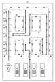
- FIG. 4 is a schematic plan view showing a floor map of the store X1.
- a plurality of product display shelves 40 are installed in the product sales area (for example, the grocery sales area) of the store X1.
- the purchaser A1 can freely move in the passage provided between the merchandise display shelves 40.
- the purchaser A1 traces the flow line Y while pushing the shopping cart B1, and finally the payment of the purchased product in the POS [point of sale system] register 50 is schematically depicted.
- the shopping cart B1 is equipped with a transmitter 10 that spontaneously intermittently transmits a unique transmitter ID at a timing corresponding to the amount of movement of the purchaser A1.
- the store X1 is provided with a plurality of receivers 20 that receive transmitter IDs transmitted from the transmitter A1 existing in the vicinity and send them to the server 30 (not shown in the figure).
- the receiver 20 is arranged on the commodity display shelf 40, but the arrangement place of the receiver 20 is not limited to this, and the receiver 20 may be arranged under the floor or ceiling of the passage. Absent.
- a circle mark on the flow line Y indicates an ID transmission position where the transmitter 10 transmits the transmitter ID.
- the transmitter 10 transmits the transmitter ID every time the charging voltage Vc reaches the operable voltage Vdrv (that is, every time the purchaser A1 moves a certain distance). Accordingly, the ID transmission positions on the flow line Y are substantially equally spaced.
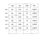
- FIG. 5 is a data table showing an example of a database managed by the server 30.
- transmitter ID TXID
- serial number SN RXID
- reception time RTC
- ⁇ Y2> to ⁇ Y8> described in the margin indicate that the purchaser A1 (transmitter 10) exists at the ID transmission positions Y2 to Y8 in FIG.
- the transmitter ID is terminal identification data (“001” in the figure) transmitted intermittently from the transmitter 10.
- the serial number SN is a count of the number of transmissions incremented by one for each transmission of the transmitter ID, and is transmitted from the transmitter 10 together with the transmitter ID (TXID).
- the serial number SN may be incremented by the control unit 14 of the transmitter 10.
- the serial number SN is not reset to the initial value when the purchase operation by the purchaser A1 starts or ends. That is, even if the purchaser A1 passes the POS register 50 and ends the use of the shopping cart B1, the serial number SN is held at the count value so far. With such a configuration, an information collection system can be constructed more easily. The technical significance of adding the serial number SN will be described later with a specific example.
- the receiver ID is terminal identification data unique to each of the plurality of receivers 20, and is comprehensively managed by the server 30.
- the server 30 holds a position database associating the receiver ID with the position information of the receiver 20 (coordinate data in the store X1) as a separate file. Therefore, when analyzing the flow line of the purchaser A1 by the server 30, not only the database of FIG. 5 but also the above-mentioned location database is used by referring to the receiver ID.
- the reception time is time data when the receiver 20 receives a transmission ID (TXID) transmitted from the transmitter 10.
- the contents of the database managed by the server 30 and its analysis method will be specifically described in accordance with the movement example of the purchaser A1.
- the transmitter 10 transmits the transmitter ID (001) and the serial number SN (for example, 0122) at the ID transmission position Y1, there is no receiver 20 that can receive this in the vicinity. Therefore, no information is stored in the database of the server 30.
- the transmitter ID (001) and serial number SN (0123) transmitted from the transmitter 10 are received by the receiver 20-1 existing in the vicinity thereof. Therefore, in the database of the server 30, TXID (001), SN (0123), RXID (01), and reception time (10:00:15) are managed in association with each other.
- the transmitter ID (001) and the serial number SN (0124) transmitted from the transmitter 10 are received by the receiver 20-2 existing in the vicinity thereof. Therefore, in the database of the server 30, TXID (001), SN (0124), RXID (02), and reception time (10:00:30) are managed in association with each other.
- the transmitter ID (001) and serial number SN (0125) transmitted from the transmitter 10 are received by the receiver 20-3 existing in the vicinity thereof. Therefore, in the database of the server 30, TXID (001), SN (0125), RXID (03), and reception time (10:01:50) are managed in association with each other.
- the transmitter ID (001) and the serial number SN (0126) transmitted from the transmitter 10 are not received by any of the receivers 20 due to some communication failure (collision or the like). Therefore, no information is stored in the database of the server 30.
- the transmitter ID (001) and the serial number SN (0127) transmitted from the transmitter 10 are received by the receiver 20-4 existing in the vicinity thereof. Therefore, in the database of the server 30, TXID (001), SN (0127), RXID (04), and reception time (10:02:30) are managed in association with each other.
- the transmitter ID (001) and serial number SN (0128) transmitted from the transmitter 10 are received by the receiver 20-5 existing in the vicinity thereof. Therefore, in the database of the server 30, TXID (001), SN (0128), RXID (05), and reception time (10:02:45) are managed in association with each other.
- the transmitter ID (001) and serial number SN (0129) transmitted from the transmitter 10 are received by the receiver 20-6 existing in the vicinity thereof. Therefore, in the database of the server 30, TXID (001), SN (0129), RXID (06), and reception time (10:04:05) are managed in association with each other.
- the moving speed of the buyer A1 can be grasped by subtracting the series of reception times. For example, from each reception time at the ID transmission positions Y2 to Y4, the purchaser A1 moves from the vicinity of the receiver 20-1 to the vicinity of the receiver 20-2 in 15 seconds, whereas the vicinity of the receiver 20-2 It can be seen that it took 1 minute and 20 seconds to move from to the vicinity of the receiver 20-3. From this, the purchaser A1 passes through the goods displayed between the receiver 20-1 and the receiver 20-2 without showing much interest, but the receiver 20-2 and the receiver 20- It can be seen that there is a possibility that the product displayed between 3 and 3 may have stopped.
- the POS register 50 is installed in the purchase information of the purchaser A1 (segment information such as purchase item, sex, age group, etc.) and the shopping cart B1.
- the transmitter ID of the transmitter 10 is associated and sent to the server 30.
- the server 30 can manage the above-described database relating to the flow line Y of the buyer A1 and the purchase information of the buyer A1 by linking each other. Therefore, for example, in the store X1, it is possible to investigate a series of purchasing behaviors such as where the purchaser A1 passes, where and how much, and as a result, what has been purchased without human intervention. it can.
- the survey results can be used for various store improvement operations, such as determining the number of products purchased and product composition, changing display methods, and optimizing passage layout and passage width.
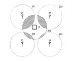
- FIG. 6 is a conceptual diagram illustrating an example of a position detection method based on reception intensity. In the example of this figure, it is assumed that there are four receivers 21 to 24 around the transmitter 10, and the receivers 21 to 24 receive transmitter IDs with different reception intensities.
- the radio wave reachable range Z10 of the transmitter 10 and the receivable ranges Z21 to Z24 of the receivers 21 to 24 are indicated by broken-line circles so that the difference in received intensity can be visually understood.
- the overlapping area (hatched portion) is depicted as the received intensity.
- the reception intensity at the receiver 21 is the highest
- the reception intensity at the receivers 22 and 23 follows
- the reception intensity at the receiver 24 is the lowest.
- the relative distance between the transmitter 10 and the receivers 21 to 24 is determined from the relative ratio between the combination and the reception intensity. Can be estimated. Therefore, by managing the server 30 in association with the transmitter ID and the reception intensity at the receivers 21 to 24, it is possible to obtain more detailed location information of the buyer A1 (transmitter 10).
- the position detection method based on the reception intensity is mainly applied.
- the transmitter ID transmitted from the transmitter 10 reaches a plurality of receivers 20. Therefore, with respect to one transmission operation by the transmitter 10, the reception operation is successfully performed by a plurality of (for example, three) receivers 20.
- a plurality of (for example, three) different receiver IDs and reception intensity data are recorded in association with each other simultaneously (or almost simultaneously).
- the record data stored in the server 30 is a variable-length record. That is, time stamp, transmitter ID, serial number SN, first receiver ID, first reception intensity, second receiver ID, second reception intensity,..., Nth receiver ID, nth Reception strength of ⁇ record end>.
- FIG. 7 is a diagram showing variations of store equipment to which the transmitter 10 is mounted.
- the transmitter 10 is mounted on the shopping cart B1, the shopping basket B1 ′, and the store entrance permit B1 ′′ that are highly inevitably carried by the purchaser A1 at the store X1. If the transmitter 10 is mounted on such store equipment, the purchase behavior can be analyzed without giving the buyer A1 the discomfort of being “always under surveillance”. It becomes.
- the indoor floor of the store X1 is assumed as the monitoring target area for monitoring the purchase behavior of the purchaser A1, but the monitoring target area is not limited to this and is indoor and outdoor. Regardless of the market, it is possible to set the entire market (flea market venue, shopping street, etc.) where products are bought and sold as the monitoring target area.
- the information collection system 1 is not necessarily used only as a marketing tool, but can be applied to a wide range of uses as a means for collecting position information of a moving body that freely moves in the monitoring target area. It is. Below, the variation is demonstrated easily.
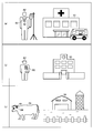
- FIG. 8 is a diagram showing variations of the moving object and the monitoring target area.
- a patient position grasping system in which the moving body is the patient A2 and the monitoring target area is the hospital X2 is shown.
- the transmitter 10 When constructing such a system, it is desirable to mount the transmitter 10 on the patient label B2 or the like that the patient A2 always wears.
- the patient A2 may be read as a care recipient and the hospital X2 may be read as a care facility. It is also assumed that the patient or care recipient is inadvertently falling over without the eyes of a doctor, nurse, or care staff. Therefore, when the power supply of the transmitter 10 has a surplus capacity, the transmitter 10 is provided with an attitude sensor or the like, and the server 30 side always monitors the sensing result transmitted with the transmitter ID (whether there is a fall or the like). It may be.
- (B) column shows a student position grasping system in which the moving object is the student A3 and the monitoring target area is the school X3.
- the moving object is the student A3
- the monitoring target area is the school X3.
- mount the transmitter 10 on the name tag B3 or the like it is desirable to mount the transmitter 10 on the name tag B3 or the like that the student A3 always wears.
- the student A3 may be read as a kindergarten and the school X3 may be read as a kindergarten or a nursery school.
- (C) column shows a livestock position grasping system in which the moving body is the livestock A4 and the monitoring target area is the breeding ground X4.
- the transmitter 10 may be embedded in the livestock A4.
- livestock A4 may be read as poultry.
- the information collection system can be used, for example, as a marketing tool for grasping or analyzing a buyer's flow line and purchase behavior in a store.
Landscapes
- Engineering & Computer Science (AREA)
- Physics & Mathematics (AREA)
- Business, Economics & Management (AREA)
- General Physics & Mathematics (AREA)
- Theoretical Computer Science (AREA)
- Accounting & Taxation (AREA)
- Strategic Management (AREA)
- Microelectronics & Electronic Packaging (AREA)
- Computer Hardware Design (AREA)
- Finance (AREA)
- Development Economics (AREA)
- Entrepreneurship & Innovation (AREA)
- Economics (AREA)
- General Business, Economics & Management (AREA)
- Electromagnetism (AREA)
- Toxicology (AREA)
- Health & Medical Sciences (AREA)
- Marketing (AREA)
- General Health & Medical Sciences (AREA)
- Computer Networks & Wireless Communication (AREA)
- Computer Vision & Pattern Recognition (AREA)
- Artificial Intelligence (AREA)
- Game Theory and Decision Science (AREA)
- Radar, Positioning & Navigation (AREA)
- Human Resources & Organizations (AREA)
- Operations Research (AREA)
- Quality & Reliability (AREA)
- Remote Sensing (AREA)
- Data Mining & Analysis (AREA)
- Tourism & Hospitality (AREA)
- Management, Administration, Business Operations System, And Electronic Commerce (AREA)
- Accommodation For Nursing Or Treatment Tables (AREA)
- Alarm Systems (AREA)
- Cash Registers Or Receiving Machines (AREA)
Abstract
情報収集システム1は、移動体(購買者)A1に伴って移動可能であり、移動体A1の移動量に応じたタイミングで発信機IDを自発的に間欠発信する自立電源型の発信機10と;移動体A1が自由に移動することのできる監視対象エリアXに設けられており、その近傍に存在する発信機10から発信された発信機IDを受信する複数の受信機20と;発信機IDと、発信機IDを受信した受信機20の位置情報(受信機ID)と、発信機IDの受信時刻とを関連付けて管理するサーバ30と;を有する。
Description
本発明は、情報収集システムに関する。
特許文献1や特許文献2には、ショッピングカートや買い物かごに搭載されたICタグの識別IDを店舗内に複数設けられたICタグリーダーで読み取り、ICタグ及びICタグリーダーの各識別IDとその読み取り時刻とを関連付けて管理することにより、店舗内における購買者の位置情報を収集する情報収集システムが開示されている。
しかしながら、上記従来の情報収集システムでは、ICタグとして受電型の発信機(パッシブタグ)を用いることが想定されており、自立電源型の発信機(アクティブタグ)を用いる際のシステム設計(複雑な調停処理を要することなくコリジョンを未然に回避することのできる発信機の設計など)については、何ら検討されていなかった。
本明細書中に開示されている発明は、本願の発明者によって見出された上記の課題に鑑み、自立電源型の発信機を用いた情報収集システムを提供することを目的とする。
本明細書中に開示された情報収集システムは、移動体に伴って移動可能であり、前記移動体の移動量に応じたタイミングで発信機IDを自発的に間欠発信する自立電源型の発信機と;前記移動体が自由に移動することのできる監視対象エリア内に設けられており、その近傍に存在する発信機から発信された発信機IDを受信する複数の受信機と;前記発信機IDと、前記発信機IDを受信した受信機の位置情報と、前記発信機IDの受信時刻とを関連付けて管理するサーバと;を有する構成(第1の構成)である。
なお、上記第1の構成から成る情報収集システムにおいて、前記発信機は、運動エネルギーを電気エネルギーに変換する発電部と、前記発電部で生成された電気エネルギーを蓄える蓄電部と、前記蓄電部に所定量の電気エネルギーが蓄えられる毎にその供給を受けて前記発信機IDを発信する発信部と、を含む構成(第2の構成)にするとよい。
また、上記第1の構成から成る情報収集システムにおいて、前記発信機は、キャスター回転数を計測する回転計測部と、前記キャスター回転数が所定値に達する毎に前記発信機IDを発信する発信部と、を含む構成(第3の構成)にするとよい。
また、上記第1の構成から成る情報収集システムにおいて、前記発信機は、歩数を計測する歩数計測部と、前記歩数が所定値に達する毎に前記発信機IDを発信する発信部と、を含む構成(第4の構成)にするとよい。
また、上記第1~第4いずれかの構成から成る情報収集システムにおいて、前記発信機は、前記発信機IDを発信する毎にインクリメントされるシリアルナンバーを前記発信機IDと共に発信する構成(第5の構成)にするとよい。
また、上記第1~第5いずれかの構成から成る情報収集システムにおいて、前記サーバは、前記発信機IDと共に前記受信機での受信強度も関連付けて管理する構成(第6の構成)にするとよい。
また、上記第1~第6いずれかの構成から成る情報収集システムにおいて、前記移動体は購買者であり、前記監視対象エリアは店舗または市場である構成(第7の構成)にするとよい。
また、上記第7の構成から成る情報収集システムにおいて、前記発信機は、前記購買者が携行するショッピングカート、買い物かご、ないしは、入店許可証に搭載されている構成(第8の構成)にするとよい。
また、上記第7または第8の構成から成る情報収集システムは、前記購買者の購入情報と前記発信機IDを関連付けて前記サーバに送出するレジスターをさらに有する構成(第9の構成)にするとよい。
また、上記第1~第6いずれかの構成から成る情報収集システムにおいて、前記移動体は、患者または要介護者、生徒または園児、若しくは、家畜または家禽であり、前記監視対象エリアは、病院または介護施設、学校または幼稚園または保育園、若しくは、飼育場である構成(第10の構成)にするとよい。
本明細書中に開示されている発明によれば、自立電源型の発信機を用いた情報収集システムを提供することが可能となる。
<情報収集システム>
図1は、情報収集システムの一構成例を示す概念図である。本構成例の情報収集システム1は、少なくとも一つ(通常は複数)の発信機10と、複数の受信機20と、サーバ30と、を有する。
図1は、情報収集システムの一構成例を示す概念図である。本構成例の情報収集システム1は、少なくとも一つ(通常は複数)の発信機10と、複数の受信機20と、サーバ30と、を有する。
発信機10は、購買者A1(移動体の一例)によって操作されるショッピングカートB1(店舗備品の一例)に搭載されており、購買者A1の歩行に伴って店舗X1(監視対象エリアの一例)内を移動する。発信機10は、外部から電力供給を受けずに動作することが可能な自立電源型(いわゆるアクティブタグ)である。発信機10は、その特徴的な動作として、購買者A1の移動量に応じたタイミングで、各々に固有の発信機IDを自発的に間欠発信する。このような発信動作の技術的意義については、後ほど詳細に説明する。
受信機20は、購買者A1が自由に移動することのできる店舗X1内に分散して設けられており、その近傍に存在する発信機A1から非同期で発信された発信機IDを受信するための受信アンテナである。受信機20は、サーバ30に有線または無線で接続されており、受信した発信機IDをサーバ30に伝達する。受信機20には、それぞれ固有の受信機IDが付されており、サーバ30によって一元的にID管理されている。
サーバ30は、発信機10から発信された発信機IDと、その発信機IDを受信した受信機20の位置情報(受信機IDと関連付けられた店舗X1内での座標データ)と、発信機IDの受信時刻(RTC[real time clock]データ)とを関連付けて管理する。サーバ30は、店舗X1に設けてもよいし、複数の店舗X1を統括的に管理する中央管理施設に設けてもよい。サーバ30で管理されるデータベースの内容については、後ほど具体例を挙げて説明する。
<発信機>
図2は、発信機10の一構成例を示すブロック図である。本構成例の発信機10は、発電部11と、蓄電部12と、記憶部13と、制御部14と、発信部15と、アンテナ部16と、を含む。
図2は、発信機10の一構成例を示すブロック図である。本構成例の発信機10は、発電部11と、蓄電部12と、記憶部13と、制御部14と、発信部15と、アンテナ部16と、を含む。
発電部11は、購買者A1の歩行に伴う運動エネルギーを電気エネルギーに変換する。発電部11としては、例えば、ショッピングカートB1に設けられたキャスターの回転運動によって発電する整流子発電機や、発信機10に加わる振動によって発電するMEMS[micro electro-mechanical systems]振動発電機を用いることができる。このような発電部11を備える構成であれば、電池の交換作業や充電作業が一切不要となる。従って、発信機10を外部電源型(いわゆるパッシブタグ)とした場合と同等のメンテナンスフリーを実現することが可能となる。
蓄電部12は、発電部11で生成された電気エネルギーを蓄えて充電電圧Vcを発信機10の各部に出力する。蓄電部12としては、キャパシタやリチウムイオン二次電池などを用いることができる。
記憶部13は、発信機10に固有の発信機IDを不揮発的に記憶する。記憶部13としては、EEPROM[electrically erasable programmable read-only memory]、OTPROM[one time programmable ROM]、或いは、フラッシュメモリなどを用いることができる。
制御部14は、充電電圧Vcが所定の動作可能電圧Vdrvに達する毎にその供給を受けて動作し、記憶部13のアクセス制御(発信機IDの読み出し制御)や発信部15の駆動制御(発信機IDに応じたアンテナ駆動信号の変調制御)などを行う。
発信部15は、充電電圧Vcが所定の動作可能電圧Vdrvに達する毎にその供給を受けて動作し、制御部14から入力されるアンテナ駆動信号に基づいてアンテナ部16を駆動することにより、発信機IDの発信処理を行う。
アンテナ部16は、発信機IDに応じた変調処理が施されている電気信号を電波に変換して発信機1の外部に出力する。
<発信タイミング>
図3は、購買者の移動量(延いては発電部11の発電量)と発信タイミングとの関係を示すタイミングチャートであり、(a)欄及び(b)欄には、それぞれ、異なる購買者A1a及びA1bに各々携行されている発信機10の充電電圧Vcが時間的に変化する様子が描写されている。
図3は、購買者の移動量(延いては発電部11の発電量)と発信タイミングとの関係を示すタイミングチャートであり、(a)欄及び(b)欄には、それぞれ、異なる購買者A1a及びA1bに各々携行されている発信機10の充電電圧Vcが時間的に変化する様子が描写されている。
購買者A1a及びA1bは、所望の商品を購入するために店舗X1内を各々自由に移動する。ただし、各人の歩行速度や足を止めるタイミングは、当然のことながら不規則的に変化する。すなわち、購買者A1の歩行に伴う充電電圧Vcの充電速度は、店舗X1内における購買者A1a及びA1bの移動の仕方に応じて逐次的に変化する。
その結果、充電電圧Vcが動作可能電圧Vdrvに達するまでの所要時間が千差万別となるので、発信機IDの発信タイミングも自ずとランダムなものとなる。例えば、(a)欄の例では、時刻t11、時刻t12、及び、時刻t13において、それぞれ発信IDの発信タイミングが到来しているが、(b)欄の例では、時刻t21、時刻t22、及び、時刻t23において、それぞれ発信IDの発信タイミングが到来している。
このように、購買者A1の移動量に応じたタイミングで、各々に固有の発信機IDを自発的に間欠発信することにより、複雑な調停処理を要することなくコリジョンを未然に回避することが可能となる。
また、上記の構成によれば、充電電圧Vcが動作可能電圧Vdrvに達しない限り、制御部14や発信部15は動作することができない。従って、別途のイネーブル制御などを要することなく、発信機IDの発信タイミングを決定することができるので、発信機10を極めてシンプルに構成することが可能となる。また、購買者A1が足を止めている間は発信動作が行われないので、不必要な通信混雑も避けることができる。
ただし、購買者A1の移動量に応じた発信タイミングの制御手法については、これに限定されるものではなく、例えば、ショッピングカートB1のキャスター回転数を計測する回転計測部を別途設けた上で、キャスター回転数が所定値に達する毎に発信機IDを発信するように発信部15を制御してもよい。また、発信機10をショッピングカートB1ではなく買い物かごB1’(図7(b)を参照)に搭載する場合には、購買者A1の歩数を計測する歩数計測部を別途設けた上で、歩数が所定値に達する毎に発信機IDを発信するように発信部15を制御してもよい。
これらの構成を採用した場合には、回転計測部や歩数計測部が別途必要になるものの、購買者A1の移動と発電動作とを切り離すことができる。従って、発電部11として光電変換素子(光電池)を用いたり、或いは、発電部11に代えて乾電池や充電池などを用いたりすることが可能となり、システム設計の幅が広がる。
なお、本図の例では、発信機IDの発信動作毎に充電電圧Vcが完全に消費されているが、制御部14を継続的に動作させておく必要がある場合には、発信機IDの発信動作を行った後も制御部14が動作し得るだけの充電電圧Vcが残るように、動作可能電圧Vdrvを引き上げておけばよい。
<購買行動分析>
図4は、店舗X1のフロアマップを示す模式平面図である。店舗X1の商品売り場(例えば食料品売り場)には、複数の商品陳列棚40が設置されている。購買者A1は、商品陳列棚40の間に設けられた通路を自由に移動することができる。本図では、購買者A1がショッピングカートB1を押しながら動線Yを辿り、最終的にPOS[point of sale system]レジスター50で購入商品の決済を行った様子が模式的に描写されている。
図4は、店舗X1のフロアマップを示す模式平面図である。店舗X1の商品売り場(例えば食料品売り場)には、複数の商品陳列棚40が設置されている。購買者A1は、商品陳列棚40の間に設けられた通路を自由に移動することができる。本図では、購買者A1がショッピングカートB1を押しながら動線Yを辿り、最終的にPOS[point of sale system]レジスター50で購入商品の決済を行った様子が模式的に描写されている。
なお、ショッピングカートB1には、購買者A1の移動量に応じたタイミングで各々に固有の発信機IDを自発的に間欠発信する発信器10が搭載されている。また、店舗X1には、近傍に存在する発信機A1から発信された発信機IDを受信してサーバ30(本図では不図示)に送出する受信機20が複数設けられている。本図では、図示の便宜上、商品陳列棚40に受信機20が配置されているが、受信機20の配置箇所はこれに限らず、通路の床下や天井に受信機20を配置しても構わない。
動線Y上の丸マークは、それぞれ、発信機10が発信機IDを発信したID発信位置を示している。先に述べたように、発信機10は、充電電圧Vcが動作可能電圧Vdrvに達する毎に(すなわち購買者A1が一定距離を移動する毎に)発信機IDを発信する。従って、動線Y上のID発信位置はほぼ等間隔となる。
以下では、購買者A1が商品売り場に入場した直後のID発信位置Y1~Y8に着目しながら、サーバ30で管理されるデータベースの内容について具体的に説明する。
図5は、サーバ30で管理されるデータベースの一例を示すデータテーブルである。データベースでは、発信機ID(TXID)と、シリアルナンバーSNと、受信機ID(RXID)と、受信時刻(RTC)と、が相互に関連付けられている。なお、欄外に記載された<Y2>~<Y8>は、購買者A1(発信機10)が図4のID発信位置Y2~Y8に存在することを示している。
発信機ID(TXID)は、発信機10から間欠的に発信される端末識別データ(本図では「001」)である。
シリアルナンバーSNは、発信機IDの発信毎に1つずつインクリメントされていく発信回数カウントであり、発信機ID(TXID)と共に発信機10から発信される。シリアルナンバーSNは、発信機10の制御部14でインクリメントすればよい。シリアルナンバーSNは、購買者A1による購買動作の開始時点や終了時点で初期値にリセットされるものではない。すなわち、購買者A1がPOSレジスター50を通過してショッピングカートB1の使用を終了しても、シリアルナンバーSNはそれまでのカウント値に保持される。このような構成とすることにより、情報収集システムをより簡易に構築することが可能となる。シリアルナンバーSNを付加することの技術的意義については、後ほど具体例を挙げて説明する。
受信機ID(RXID)は、複数の受信機20に各々固有の端末識別データであり、サーバ30によって統括的に管理されている。なお、サーバ30は、受信機IDと受信機20の位置情報(店舗X1内での座標データ)とを関連付けた位置データベースを別ファイルとして保持している。従って、購買者A1の動線をサーバ30で分析する際には、図5のデータベースだけでなく、受信機IDを基にして上記の位置データベースが参照して使用される。
受信時刻(RTC)は、発信機10から発信された発信ID(TXID)を受信機20が受信したときの時刻データである。
以下では、図4左端の商品陳列棚40に並べられた受信機20-1~20-6の受信機ID(RXID)が各々「01」~「06」であるものとし、動線Yで示した購買者A1の移動例に即して、サーバ30で管理されるデータベースの内容やその分析手法を具体的に説明する。
ID発信位置Y1において、発信機10が発信機ID(001)とシリアルナンバーSN(例えば0122)を発信したとき、その近傍にはこれを受信できる受信機20が1つも存在しない。従って、サーバ30のデータベースには、何ら情報が格納されない。
ID発信位置Y2において、発信機10から発信された発信機ID(001)とシリアルナンバーSN(0123)は、その近傍に存在する受信機20-1により受信される。従って、サーバ30のデータベースでは、TXID(001)、SN(0123)、RXID(01)、及び、受信時刻(10:00:15)が相互に関連付けて管理される。
ID発信位置Y3において、発信機10から発信された発信機ID(001)とシリアルナンバーSN(0124)は、その近傍に存在する受信機20-2により受信される。従って、サーバ30のデータベースでは、TXID(001)、SN(0124)、RXID(02)、及び、受信時刻(10:00:30)が相互に関連付けて管理される。
ID発信位置Y4において、発信機10から発信された発信機ID(001)とシリアルナンバーSN(0125)は、その近傍に存在する受信機20-3により受信される。従って、サーバ30のデータベースでは、TXID(001)、SN(0125)、RXID(03)、及び、受信時刻(10:01:50)が相互に関連付けて管理される。
ID発信位置Y5において、発信機10から発信された発信機ID(001)とシリアルナンバーSN(0126)は、何らかの通信障害(コリジョンなど)によって、いずれの受信機20でも受信されていない。従って、サーバ30のデータベースには、何ら情報が格納されない。
ID発信位置Y6において、発信機10から発信された発信機ID(001)とシリアルナンバーSN(0127)は、その近傍に存在する受信機20-4により受信される。従って、サーバ30のデータベースでは、TXID(001)、SN(0127)、RXID(04)、及び、受信時刻(10:02:30)が相互に関連付けて管理される。
ID発信位置Y7において、発信機10から発信された発信機ID(001)とシリアルナンバーSN(0128)は、その近傍に存在する受信機20-5により受信される。従って、サーバ30のデータベースでは、TXID(001)、SN(0128)、RXID(05)、及び、受信時刻(10:02:45)が相互に関連付けて管理される。
ID発信位置Y8において、発信機10から発信された発信機ID(001)とシリアルナンバーSN(0129)は、その近傍に存在する受信機20-6により受信される。従って、サーバ30のデータベースでは、TXID(001)、SN(0129)、RXID(06)、及び、受信時刻(10:04:05)が相互に関連付けて管理される。
ここまでのデータベース内容から分析される購買者A1の購買行動について説明する。まず、上記一連の受信機ID(より詳細には受信機IDに紐付けられている各受信機の位置情報)を時系列的に繋げていくことにより、購買者A1の動線Y(例えば、店舗X1の商品売り場に入場してから、図4左端の商品陳列棚40に沿って商品売り場の奥へと通路を進んでいったこと)が分かる。
また、上記一連の受信時刻を差分することにより、購買者A1の移動速度を把握することができる。例えば、ID発信位置Y2~Y4での各受信時刻から、購買者A1は、受信機20-1近傍から受信機20-2近傍まで15秒で移動したのに対して、受信機20-2近傍から受信機20-3近傍まで移動するには1分20秒を要したことが分かる。このことから、購買者A1は、受信機20-1と受信機20-2との間に陳列された商品にはさほど関心を示さずに通過したが、受信機20-2と受信機20-3との間に陳列された商品には興味を持って足を止めた可能性があることが分かる。
また、ID発信位置Y4~Y6に着目すると、シリアルナンバーSNが1つ抜けていることを把握することができる。このように、発信機ID(TXID)にシリアルナンバーSNを付しておけば、何らかの要因で通信が不成立となった場合であっても、データベースの内容(本図の例では、通信不成立となったID発信位置Y5の座標や、発信機IDを正しく受信できていたと仮定した場合の受信時刻)を補完することが可能となる。また、ID発信位置Y5を推定することができれば、その通信が不成立となった要因(受信機20の故障や配置ミスなど)を速やかに調査ないし改善することも可能となる。
また、購買者A1が最終的に購入商品の決済を行う際、POSレジスター50は、購買者A1の購入情報(購入品目、性別、年齢層などのセグメント情報)と、ショッピングカートB1に搭載された発信機10の発信機IDとを関連付けてサーバ30に送出する。
このような情報収集システム1を構築することにより、サーバ30では、購買者A1の動線Yに関する先述のデータベースと購買者A1の購入情報とを互いにリンクさせて管理することができる。従って、例えば、店舗X1内において、購買者A1がどこの通路を通り、どの場所にどれだけ滞在し、結果として何を購入したかという一連の購買行動を人手を要さずに調査することができる。その調査結果は、商品の仕入れ数や商品構成の決定、陳列方法の変更、通路レイアウトや通路幅の最適化など、様々な店舗改善業務に活用することが可能である。
<詳細位置検出>
図6は、受信強度に基づく位置検出手法の一例を示す概念図である。本図の例では、発信機10の周囲に4つの受信機21~24が存在し、受信機21~24では、互いに異なる受信強度で発信機IDが受信されているものとする。
図6は、受信強度に基づく位置検出手法の一例を示す概念図である。本図の例では、発信機10の周囲に4つの受信機21~24が存在し、受信機21~24では、互いに異なる受信強度で発信機IDが受信されているものとする。
なお、本図では、受信強度の差違を視覚的に理解できるように、発信機10の電波到達範囲Z10と受信機21~24の受信可能範囲Z21~Z24が破線円で示されており、互いの重複面積(ハッチング部分)が受信強度であるように描写されている。本図の例では、受信機21での受信強度が最も大きく、受信機22及び23での受信強度がそれに続いており、受信機24での受信強度が最も小さいことが分かる。
このように、発信機10から発信された発信機IDを複数の受信機21~24で受信した場合、その組み合わせと受信強度の相対比から、発信機10と受信機21~24との相対距離を推定することができる。従って、サーバ30により、発信機IDと共に受信機21~24での受信強度も関連付けて管理することにより、さらに詳細な購買者A1(発信機10)の位置情報を得ることが可能となる。
店舗X1に情報収集システムを導入する場合には、受信強度に基づく位置検出手法の適用が主になると考えられる。当該手法を適用する場合には、発信機10から発信された発信機IDが複数の受信機20まで届く。従って、発信機10による一度の発信動作に対して、複数台(例えば3台)の受信機20で受信動作に成功する。その結果、同一の発信機ID及びシリアルナンバーSNに対して、複数台分(例えば3台分)の異なる受信機ID及び受信強度データが同時(またはほぼ同時)にそれぞれ関連付けられて記録される。
この場合、サーバ30に格納される記録データは、可変長のレコードとする方がよい。すなわち、タイムスタンプ、発信機ID、シリアルナンバーSN、第1の受信機ID、第1の受信強度、第2の受信機ID、第2の受信強度、…、第nの受信機ID、第nの受信強度、<レコードend>の形である。
このような記録データに対してサーバ30などによる分析を行うときには、別途のデータベースに格納されている各受信機の位置情報と、各々の受信強度を用いることにより、三点法のような方法で各受信機から送信機に対する相対的な距離を考えて、送信機の位置(座標)を求めることができる。
ただし、店舗などでは、頻繁に棚の商品が入れ替えられるなどして、各受信機において送信機に対する相対距離と受信強度との関係がその時々で一定でない場合がある。このような問題を解消するためには、キャリブレーションを行うことが望ましい。例えば、予め座標の分かっている固定ポイント(通路など)から強制的に信号を発信して各受信機での受信強度を記録する、という動作を複数の固定ポイントで順次実施する。そして、その結果をサーバ30で補正値として使用すればよい。
<変形例>
図7は、発信機10の搭載先となる店舗備品のバリエーションを示す図である。(a)欄~(c)欄では、購買者A1が店舗X1で携行する必然性の高いショッピングカートB1、買い物かごB1’、及び、入店許可証B1”に発信機10が搭載されている。このような店舗備品に発信機10を搭載しておけば、購買者A1に対して、「常に監視下に置かれている」という不快感を与えることなく、その購買行動を分析することが可能となる。
図7は、発信機10の搭載先となる店舗備品のバリエーションを示す図である。(a)欄~(c)欄では、購買者A1が店舗X1で携行する必然性の高いショッピングカートB1、買い物かごB1’、及び、入店許可証B1”に発信機10が搭載されている。このような店舗備品に発信機10を搭載しておけば、購買者A1に対して、「常に監視下に置かれている」という不快感を与えることなく、その購買行動を分析することが可能となる。
なお、これまでの説明では、購買者A1の購買行動を監視する監視対象エリアとして、店舗X1の屋内フロアを想定しているが、監視対象エリアはこれに限定されるものではなく、屋内及び屋外を問わず、商品の売買が行われる市場全般(フリーマーケット会場や商店街など)を監視対象エリアに設定することが可能である。
また、情報収集システム1は、必ずしもマーケティングツールとしてのみ用いられるものではなく、監視対象エリア内を自由に移動する移動体の位置情報を収集するための手段として、広範な用途に適用することが可能である。以下では、そのバリエーションについて簡単に説明する。
図8は、移動体及び監視対象エリアのバリエーションを示す図である。(a)欄では、移動体を患者A2とし、監視対象エリアを病院X2とした患者位置把握システムが示されている。このようなシステムを構築する場合、患者A2が常に身に着けている患者ラベルB2などに発信機10を搭載することが望ましい。また、患者A2を要介護者に読み替えて病院X2を介護施設に読み替えてもよい。なお、患者や要介護者は、医師や看護師、或いは、介護スタッフの目が届かないところで不慮に転倒している場合なども想定される。そのため、発信機10の自立電源に余力がある場合には、発信機10に姿勢センサなどを設け、発信機IDと共に発信されるセンシング結果(転倒の有無など)をサーバ30側で常に監視するようにしてもよい。
(b)欄では、移動体を生徒A3とし、監視対象エリアを学校X3とした生徒位置把握システムが示されている。このようなシステムを構築する場合、生徒A3が常に身に着けている名札B3などに発信機10を搭載することが望ましい。また、生徒A3を園児に読み替えて学校X3を幼稚園や保育園と読み替えてもよい。
(c)欄では、移動体を家畜A4とし、監視対象エリアを飼育場X4とした家畜位置把握システムが示されている。このようなシステムを構築する場合、家畜A4が常に身に着けている耳標B4などに発信機10を搭載することが望ましい。もしくは、家畜A4の体内に発信機10を埋め込んでも構わない。また、家畜A4を家禽に読み替えてもよい。
<その他の変形例>
なお、本明細書中に開示されている種々の技術的特徴は、上記実施形態のほか、その技術的創作の主旨を逸脱しない範囲で種々の変更を加えることが可能である。すなわち、上記実施形態は、全ての点で例示であって制限的なものではないと考えられるべきであり、本発明の技術的範囲は、上記実施形態の説明ではなく、特許請求の範囲によって示されるものであり、特許請求の範囲と均等の意味及び範囲内に属する全ての変更が含まれると理解されるべきである。
なお、本明細書中に開示されている種々の技術的特徴は、上記実施形態のほか、その技術的創作の主旨を逸脱しない範囲で種々の変更を加えることが可能である。すなわち、上記実施形態は、全ての点で例示であって制限的なものではないと考えられるべきであり、本発明の技術的範囲は、上記実施形態の説明ではなく、特許請求の範囲によって示されるものであり、特許請求の範囲と均等の意味及び範囲内に属する全ての変更が含まれると理解されるべきである。
本発明に係る情報収集システムは、例えば、店舗内における購買者の動線や購買行動を把握ないし分析するためのマーケティングツールとして利用することが可能である。
1 情報収集システム
10 発信機
11 発電部
12 蓄電部
13 記憶部
14 制御部
15 発信部
16 アンテナ部
20、20-1~20-6、21~24 受信機
30 サーバ
40 商品陳列棚
50 POSレジスター
A1 購買者
A2 患者
A3 生徒
A4 家畜
B1 ショッピングカート
B1’ 買い物かご
B1” 入店許可証
B2 患者ラベル
B3 名札
B4 耳標
X1 店舗
X2 病院
X3 学校
X4 飼育場
Y 動線
Y1~Y8 ID発信位置
Z10 電波到達範囲
Z21~Z24 受信可能範囲
10 発信機
11 発電部
12 蓄電部
13 記憶部
14 制御部
15 発信部
16 アンテナ部
20、20-1~20-6、21~24 受信機
30 サーバ
40 商品陳列棚
50 POSレジスター
A1 購買者
A2 患者
A3 生徒
A4 家畜
B1 ショッピングカート
B1’ 買い物かご
B1” 入店許可証
B2 患者ラベル
B3 名札
B4 耳標
X1 店舗
X2 病院
X3 学校
X4 飼育場
Y 動線
Y1~Y8 ID発信位置
Z10 電波到達範囲
Z21~Z24 受信可能範囲
Claims (10)
- 移動体に伴って移動可能であり、前記移動体の移動量に応じたタイミングで発信機IDを自発的に間欠発信する自立電源型の発信機と;
前記移動体が自由に移動することのできる監視対象エリア内に設けられており、その近傍に存在する発信機から発信された発信機IDを受信する複数の受信機と;
前記発信機IDと、前記発信機IDを受信した受信機の位置情報と、前記発信機IDの受信時刻とを関連付けて管理するサーバと;
を有することを特徴とする情報収集システム。 - 前記発信機は、
運動エネルギーを電気エネルギーに変換する発電部と、
前記発電部で生成された電気エネルギーを蓄える蓄電部と、
前記蓄電部に所定量の電気エネルギーが蓄えられる毎にその供給を受けて前記発信機IDを発信する発信部と、
を含むことを特徴とする請求項1に記載の情報収集システム。 - 前記発信機は、
キャスター回転数を計測する回転計測部と、
前記キャスター回転数が所定値に達する毎に前記発信機IDを発信する発信部と、
を含むことを特徴とする請求項1に記載の情報収集システム。 - 前記発信機は、
歩数を計測する歩数計測部と、
前記歩数が所定値に達する毎に前記発信機IDを発信する発信部と、
を含むことを特徴とする請求項1に記載の情報収集システム。 - 前記発信機は、前記発信機IDを発信する毎にインクリメントされるシリアルナンバーを前記発信機IDと共に発信することを特徴とする請求項1~請求項4のいずれか一項に記載の情報収集システム。
- 前記サーバは、前記発信機IDと共に前記受信機での受信強度も関連付けて管理することを特徴とする請求項1~請求項5のいずれか一項に記載の情報収集システム。
- 前記移動体は購買者であり、前記監視対象エリアは店舗または市場であることを特徴とする請求項1~請求項6のいずれか一項に記載の情報収集システム。
- 前記発信機は、前記購買者が携行するショッピングカート、買い物かご、ないしは、入店許可証に搭載されていることを特徴とする請求項7に記載の情報収集システム。
- 前記購買者の購入情報と前記発信機IDとを関連付けて前記サーバに送出するレジスターをさらに有することを特徴とする請求項7または請求項8に記載の情報収集システム。
- 前記移動体は、患者または要介護者、生徒または園児、若しくは、家畜または家禽であり、前記監視対象エリアは、病院または介護施設、学校または幼稚園または保育園、若しくは、飼育場であることを特徴とする請求項1~請求項6のいずれか一項に記載の情報収集システム。
Priority Applications (1)
| Application Number | Priority Date | Filing Date | Title |
|---|---|---|---|
| US15/531,016 US10891636B2 (en) | 2014-11-28 | 2015-08-03 | Information collection system |
Applications Claiming Priority (2)
| Application Number | Priority Date | Filing Date | Title |
|---|---|---|---|
| JP2014241627A JP6391446B2 (ja) | 2014-11-28 | 2014-11-28 | 情報収集システム |
| JP2014-241627 | 2014-11-28 |
Publications (1)
| Publication Number | Publication Date |
|---|---|
| WO2016084426A1 true WO2016084426A1 (ja) | 2016-06-02 |
Family
ID=56074009
Family Applications (1)
| Application Number | Title | Priority Date | Filing Date |
|---|---|---|---|
| PCT/JP2015/071952 Ceased WO2016084426A1 (ja) | 2014-11-28 | 2015-08-03 | 情報収集システム |
Country Status (3)
| Country | Link |
|---|---|
| US (1) | US10891636B2 (ja) |
| JP (1) | JP6391446B2 (ja) |
| WO (1) | WO2016084426A1 (ja) |
Families Citing this family (7)
| Publication number | Priority date | Publication date | Assignee | Title |
|---|---|---|---|---|
| KR102348926B1 (ko) * | 2015-08-25 | 2022-01-11 | 삼성전자주식회사 | 통신 시스템에서 위치 추정 방법 및 장치 |
| JP2018161357A (ja) * | 2017-03-27 | 2018-10-18 | 東洋エレクトロニクス株式会社 | ビーコン発信装置及びこれを備えたネットワークシステム |
| CN111601233B (zh) * | 2019-02-21 | 2022-06-28 | 昆山纬绩资通有限公司 | 定位装置的监控方法与系统 |
| KR102588277B1 (ko) * | 2021-03-03 | 2023-10-12 | 주식회사 성안테크 | 계산 보조기능을 구비한 장바구니 승강장치 |
| JP7565320B2 (ja) * | 2022-07-22 | 2024-10-10 | ソフトバンク株式会社 | 固定端末、サーバ、情報管理システム、および、情報管理方法 |
| JP2024104029A (ja) * | 2023-01-23 | 2024-08-02 | 大成建設株式会社 | 資機材管理システム、資機材管理装置および資機材管理方法 |
| JP2024110733A (ja) * | 2023-02-03 | 2024-08-16 | 東芝テック株式会社 | 制御方法 |
Citations (6)
| Publication number | Priority date | Publication date | Assignee | Title |
|---|---|---|---|---|
| JP2008193595A (ja) * | 2007-02-07 | 2008-08-21 | Hitachi Ltd | 通信制御装置 |
| JP2009003872A (ja) * | 2007-06-25 | 2009-01-08 | Shibuya Kogyo Co Ltd | 行動履歴管理システム |
| JP2009210516A (ja) * | 2008-03-06 | 2009-09-17 | Fuji Xerox Co Ltd | 移動体位置検出装置、移動体位置検出システム及びプログラム |
| JP2012065232A (ja) * | 2010-09-17 | 2012-03-29 | Denso Wave Inc | 無線タグシステム |
| JP2013084170A (ja) * | 2011-10-12 | 2013-05-09 | Fuji Xerox Co Ltd | 情報処理装置及び情報処理プログラム |
| JP5580469B1 (ja) * | 2013-12-23 | 2014-08-27 | 丸井 智敬 | 基地局近傍への侵入と離脱を検知するrfタグ、および、該rfタグを利用したシステム。 |
Family Cites Families (19)
| Publication number | Priority date | Publication date | Assignee | Title |
|---|---|---|---|---|
| US6008546A (en) * | 1997-05-02 | 1999-12-28 | Assembled Products Corporation | Electronic control system and collision avoidance system for an electric cart |
| JP2000357177A (ja) | 1999-06-16 | 2000-12-26 | Ichikawa Jin Shoji Kk | 店舗内の動線把握システム |
| GB0004315D0 (en) * | 2000-02-23 | 2000-04-12 | Clonts Michael | Method for on-line shopping |
| US7463143B2 (en) * | 2004-03-15 | 2008-12-09 | Arbioran | Methods and systems for gathering market research data within commercial establishments |
| JP4145839B2 (ja) * | 2004-06-29 | 2008-09-03 | 株式会社シマノ | 自転車用変速システム及び自転車 |
| JP2006309280A (ja) | 2005-04-26 | 2006-11-09 | Hitachi Software Eng Co Ltd | 非接触icタグを利用した店舗内顧客購買行動分析システム |
| JP4519706B2 (ja) * | 2005-05-02 | 2010-08-04 | 日本電信電話株式会社 | バイタルデータ監視システム、バイタルデータ測定器及び方法 |
| JP4871687B2 (ja) * | 2005-10-03 | 2012-02-08 | 日立オートモティブシステムズ株式会社 | 車両制御システム |
| US7733224B2 (en) * | 2006-06-30 | 2010-06-08 | Bao Tran | Mesh network personal emergency response appliance |
| US8207851B2 (en) * | 2006-08-16 | 2012-06-26 | James Christopher | System and method for tracking shopping behavior |
| US9111157B2 (en) * | 2006-08-16 | 2015-08-18 | Insight Holding Group, Inc. | System and method for tracking shopping behavior |
| US8344876B2 (en) * | 2008-03-13 | 2013-01-01 | Health Hero Network, Inc. | Remote motion monitoring system |
| US8909330B2 (en) * | 2009-05-20 | 2014-12-09 | Sotera Wireless, Inc. | Body-worn device and associated system for alarms/alerts based on vital signs and motion |
| US9098873B2 (en) * | 2010-04-01 | 2015-08-04 | Microsoft Technology Licensing, Llc | Motion-based interactive shopping environment |
| JP2012123638A (ja) * | 2010-12-08 | 2012-06-28 | Seiko Instruments Inc | 歩数計測装置、電子装置、歩数計、及びプログラム |
| JP5291763B2 (ja) * | 2011-06-24 | 2013-09-18 | ファナック株式会社 | エネルギー蓄積部を有するモータ駆動装置 |
| DE102013013623B4 (de) * | 2012-08-29 | 2022-06-30 | Kanzaki Kokyukoki Mfg. Co., Ltd. | Motorsteuersystem für ein mit elektrischem Motor angetriebenes Fahrzeug |
| US20140067564A1 (en) * | 2012-08-30 | 2014-03-06 | Ebay Inc. | Shopping list creator and optimizer |
| US10049281B2 (en) * | 2012-11-12 | 2018-08-14 | Shopperception, Inc. | Methods and systems for measuring human interaction |
-
2014
- 2014-11-28 JP JP2014241627A patent/JP6391446B2/ja active Active
-
2015
- 2015-08-03 WO PCT/JP2015/071952 patent/WO2016084426A1/ja not_active Ceased
- 2015-08-03 US US15/531,016 patent/US10891636B2/en active Active
Patent Citations (6)
| Publication number | Priority date | Publication date | Assignee | Title |
|---|---|---|---|---|
| JP2008193595A (ja) * | 2007-02-07 | 2008-08-21 | Hitachi Ltd | 通信制御装置 |
| JP2009003872A (ja) * | 2007-06-25 | 2009-01-08 | Shibuya Kogyo Co Ltd | 行動履歴管理システム |
| JP2009210516A (ja) * | 2008-03-06 | 2009-09-17 | Fuji Xerox Co Ltd | 移動体位置検出装置、移動体位置検出システム及びプログラム |
| JP2012065232A (ja) * | 2010-09-17 | 2012-03-29 | Denso Wave Inc | 無線タグシステム |
| JP2013084170A (ja) * | 2011-10-12 | 2013-05-09 | Fuji Xerox Co Ltd | 情報処理装置及び情報処理プログラム |
| JP5580469B1 (ja) * | 2013-12-23 | 2014-08-27 | 丸井 智敬 | 基地局近傍への侵入と離脱を検知するrfタグ、および、該rfタグを利用したシステム。 |
Also Published As
| Publication number | Publication date |
|---|---|
| JP2016103184A (ja) | 2016-06-02 |
| US20170323311A1 (en) | 2017-11-09 |
| US10891636B2 (en) | 2021-01-12 |
| JP6391446B2 (ja) | 2018-09-19 |
Similar Documents
| Publication | Publication Date | Title |
|---|---|---|
| JP6391446B2 (ja) | 情報収集システム | |
| US11936744B2 (en) | Client system, combination client system and server client system | |
| US20230266728A1 (en) | Electronic appliance control method and electronic appliance control device | |
| CN106934692B (zh) | 物品信息处理系统、方法及装置 | |
| WO2020181066A1 (en) | Methods and systems for monitoring products | |
| US20190244161A1 (en) | Inventory control | |
| KR20230079260A (ko) | 재고 시스템 및 이를 사용하는 방법 | |
| KR20100051091A (ko) | 재고 모니터링 시스템 | |
| US20180005175A1 (en) | Systems and methods of managing inventory using an rfid kanban system | |
| BRPI0908846A2 (pt) | sistema de obtenção de dados sobre o comportamento real e em tempo real do cliente durante a seleção de produtos | |
| US20210192592A1 (en) | Indoor Localization Enabled Shopping Assistance in Retail Stores | |
| CN114556455A (zh) | 使用短程通信的射频识别(rfid)标签位置验证 | |
| TW201237800A (en) | Local dispensing control system | |
| CN111164531A (zh) | 用于监视用无人机的系统、方法和装置 | |
| JP2020161126A (ja) | 在庫追跡システム | |
| US20180099185A1 (en) | Retail shopping facility workout systems and methods | |
| JP2020508275A (ja) | 商品をピッキングおよび購入するためのシステムおよび方法 | |
| US12367457B2 (en) | Systems and methods of verifying price tag label-product pairings | |
| CN114424261A (zh) | 使用声磁检测的射频识别(rfid)标签位置验证 | |
| Bendavid | RFID-enabled Real-Time Location System (RTLS) to improve hospital's operations management: An up-to-date typology | |
| WO2014124612A2 (es) | Bandejas inteligentes para punto de venta | |
| US12333488B2 (en) | Systems and methods of detecting price tags and associating the price tags with products | |
| JP2018161357A (ja) | ビーコン発信装置及びこれを備えたネットワークシステム | |
| US20240073646A1 (en) | Information processing system, information processing device, information processing method, and non-transitory storage medium | |
| CN114424262A (zh) | 使用图像数据的射频识别(rfid)标签位置验证 |
Legal Events
| Date | Code | Title | Description |
|---|---|---|---|
| 121 | Ep: the epo has been informed by wipo that ep was designated in this application |
Ref document number: 15863155 Country of ref document: EP Kind code of ref document: A1 |
|
| WWE | Wipo information: entry into national phase |
Ref document number: 15531016 Country of ref document: US |
|
| NENP | Non-entry into the national phase |
Ref country code: DE |
|
| 122 | Ep: pct application non-entry in european phase |
Ref document number: 15863155 Country of ref document: EP Kind code of ref document: A1 |