WO2016084216A1 - 空気調和機の室内機 - Google Patents
空気調和機の室内機 Download PDFInfo
- Publication number
- WO2016084216A1 WO2016084216A1 PCT/JP2014/081500 JP2014081500W WO2016084216A1 WO 2016084216 A1 WO2016084216 A1 WO 2016084216A1 JP 2014081500 W JP2014081500 W JP 2014081500W WO 2016084216 A1 WO2016084216 A1 WO 2016084216A1
- Authority
- WO
- WIPO (PCT)
- Prior art keywords
- heat exchanger
- indoor unit
- wall surface
- air conditioner
- drain pan
- Prior art date
Links
Images


Classifications
-
- F—MECHANICAL ENGINEERING; LIGHTING; HEATING; WEAPONS; BLASTING
- F24—HEATING; RANGES; VENTILATING
- F24F—AIR-CONDITIONING; AIR-HUMIDIFICATION; VENTILATION; USE OF AIR CURRENTS FOR SCREENING
- F24F1/00—Room units for air-conditioning, e.g. separate or self-contained units or units receiving primary air from a central station
- F24F1/0007—Indoor units, e.g. fan coil units
- F24F1/0018—Indoor units, e.g. fan coil units characterised by fans
- F24F1/0022—Centrifugal or radial fans
-
- F—MECHANICAL ENGINEERING; LIGHTING; HEATING; WEAPONS; BLASTING
- F24—HEATING; RANGES; VENTILATING
- F24F—AIR-CONDITIONING; AIR-HUMIDIFICATION; VENTILATION; USE OF AIR CURRENTS FOR SCREENING
- F24F1/00—Room units for air-conditioning, e.g. separate or self-contained units or units receiving primary air from a central station
- F24F1/0007—Indoor units, e.g. fan coil units
- F24F1/0059—Indoor units, e.g. fan coil units characterised by heat exchangers
-
- F—MECHANICAL ENGINEERING; LIGHTING; HEATING; WEAPONS; BLASTING
- F24—HEATING; RANGES; VENTILATING
- F24F—AIR-CONDITIONING; AIR-HUMIDIFICATION; VENTILATION; USE OF AIR CURRENTS FOR SCREENING
- F24F1/00—Room units for air-conditioning, e.g. separate or self-contained units or units receiving primary air from a central station
- F24F1/0007—Indoor units, e.g. fan coil units
- F24F1/0043—Indoor units, e.g. fan coil units characterised by mounting arrangements
- F24F1/0047—Indoor units, e.g. fan coil units characterised by mounting arrangements mounted in the ceiling or at the ceiling
-
- F—MECHANICAL ENGINEERING; LIGHTING; HEATING; WEAPONS; BLASTING
- F24—HEATING; RANGES; VENTILATING
- F24F—AIR-CONDITIONING; AIR-HUMIDIFICATION; VENTILATION; USE OF AIR CURRENTS FOR SCREENING
- F24F13/00—Details common to, or for air-conditioning, air-humidification, ventilation or use of air currents for screening
- F24F13/22—Means for preventing condensation or evacuating condensate
- F24F13/222—Means for preventing condensation or evacuating condensate for evacuating condensate
-
- F—MECHANICAL ENGINEERING; LIGHTING; HEATING; WEAPONS; BLASTING
- F24—HEATING; RANGES; VENTILATING
- F24F—AIR-CONDITIONING; AIR-HUMIDIFICATION; VENTILATION; USE OF AIR CURRENTS FOR SCREENING
- F24F13/00—Details common to, or for air-conditioning, air-humidification, ventilation or use of air currents for screening
- F24F13/24—Means for preventing or suppressing noise
Definitions
- the present invention uses a centrifugal blower provided in a housing to suck in air from the room, cools or heats the air through a heat exchanger provided on the blowout side of the centrifugal blower, and then blows out toward the room.
- the present invention relates to an indoor unit of an air conditioner.
- An air conditioner includes a compressor that compresses a refrigerant in a refrigerant circulation channel in which the refrigerant is sealed, an indoor heat exchanger that exchanges heat between the refrigerant and indoor air, an expansion valve that decompresses the refrigerant, a refrigerant, It has a refrigeration cycle in which outdoor heat exchangers that exchange heat with the outside air are sequentially arranged.
- the outdoor heat exchanger is stored in the casing of the outdoor unit together with a blower that sends air to the outdoor heat exchanger, and the indoor heat exchanger is placed in the casing of the indoor unit together with a blower that sends indoor air to the indoor heat exchanger. Stored.
- Patent Document 1 An indoor unit of an air conditioner described in Japanese Patent Application Laid-Open No. 2002-139230 (Patent Document 1) is known as a ceiling embedded cassette type indoor unit. Patent Document 1 aims to provide an indoor unit that can achieve a reduction in energy consumption, noise reduction, and downsizing by making the wind speed distribution passing through the heat exchanger uniform and sufficiently extracting the performance of the heat exchanger.
- a configuration is disclosed in which a vane for static pressure recovery is provided on the unit intake port side on the windward side of the heat exchanger (See summary).
- a heat exchanger is arranged so as to surround the periphery of the centrifugal blower, and after the air discharged from the centrifugal fan of the centrifugal blower is heat-exchanged by the heat exchanger, Is blown out.
- a drain pan for receiving water droplets attached to the heat exchanger is installed at the lower part of the heat exchanger (see paragraph 0021 and FIG. 1).
- noise reduction is achieved by providing a vane for static pressure recovery on the windward unit suction port side of the heat exchanger.
- the air conditioner indoor unit having such a structure, it is effective to increase the diameter of the centrifugal fan in order to reduce noise.
- the centrifugal fan is enlarged in a similar shape, the distance between the discharge port of the centrifugal fan and the drain pan approaches. If the distance between the discharge port of the centrifugal fan and the drain pan is too close, the air flow interferes with the drain pan and noise increases. For this reason, although the diameter of the centrifugal fan was increased, there was a problem that noise could not be reduced sufficiently.
- An object of the present invention is to provide an indoor unit of an air conditioner that can prevent an increase in noise caused by interference of a flow of air discharged from a centrifugal fan with a drain pan.
- an indoor unit of an air conditioner of the present invention includes an indoor unit suction port that sucks indoor air into the device, a centrifugal blower that discharges air sucked from the indoor unit suction port, and A heat exchanger that cools or heats the air provided on the discharge side of the centrifugal blower, an outlet that blows out air provided on the downstream side of the heat exchanger, and a heat exchanger that is provided below the heat exchanger
- a drain pan that receives the generated condensed water, and the drain pan has a wall surface portion that rises upward from an end portion located on the upstream side and an end portion located on the downstream side with respect to the heat exchanger, and the centrifugal blower
- the indoor unit of the air conditioner provided at a position higher than the upper end of the wall surface portion
- the lower end of the discharge port is located upstream of the heat exchanger of the drain pan
- the drain pan is formed such that an upper end of the wall surface portion positioned on the upstream side with respect to the heat exchanger
- air is sucked from the room through the centrifugal fan provided in the housing, and after cooling or heating the air through the heat exchanger provided on the blowout side of the centrifugal fan, the air is directed indoors.
- the indoor unit of the air conditioner that blows out it is possible to suppress an increase in noise caused by the flow of air discharged from the centrifugal blower interfering with the drain pan disposed at the lower part of the heat exchanger.
- Sectional drawing which shows the indoor unit of the air conditioner of 1st Example which concerns on this invention Sectional drawing which shows the indoor unit of the air conditioner of 2nd Example which concerns on this invention.
- Sectional drawing which shows the indoor unit of the air conditioner of the 3rd Example which concerns on this invention Sectional drawing which shows the indoor unit of the air conditioner of the 4th Example which concerns on this invention.
- FIG. 1 is a cross-sectional view showing an indoor unit of an air conditioner according to a first embodiment of the present invention.
- upstream side and downstream side represent “upstream side” and “downstream side” in the air flow direction (airflow direction).
- This indoor unit 100A includes a decorative panel 1 and a casing 2 connected to the decorative panel 1.
- the decorative panel 1 is provided with a suction grill (indoor unit suction port) 3 at the center, and an outlet (indoor unit outlet) 12 provided with a wind direction plate 4 is disposed around it.
- a centrifugal blower 5 including a motor 6 and a centrifugal fan 7 connected to a shaft of the motor 6 is installed in the housing 2.
- the centrifugal fan 7 is rotated, and as indicated by an arrow 15 in FIG. 1, the indoor air flows through the suction grill 3, the filter 16 installed in the suction grill 3, and the bell installed in the housing 2. It is sucked into the suction port 7 a of the centrifugal fan 7 through the mouse 10 and discharged from the discharge port 7 b of the centrifugal fan 7 as indicated by an arrow 18.
- An indoor heat exchanger 8 is disposed so as to surround the centrifugal blower 5, and the air discharged from the centrifugal fan 7 is heat-exchanged by the indoor heat exchanger 8, and then the air outlet 12 as indicated by an arrow 17. It is blown out more indoors.
- a drain pan 9 for receiving condensed water generated in the indoor heat exchanger 8 at the time of cooling is installed below the indoor heat exchanger 8.
- the suction grill 3 is detachable from the decorative panel 1 together with the filter 16, and the filter 16 is easy to clean.
- an electrical component box 11 that houses a control board (not shown) for controlling the operation of the indoor unit 100A is installed.
- maintenance of the electrical component box 11 can be performed by opening the suction grill 13.
- the bell mouth 10 is attached to the inner periphery of the drain pan 9 from below. Accordingly, maintenance such as replacement of the centrifugal fan 7 and the motor 6 can be easily performed by opening the suction grill 3 and removing the bell mouth 10.
- the centrifugal blower 5, the indoor heat exchanger 8, the drain pan 9, the bell mouth 10, the electrical component box 11, and the filter 16 are in a space surrounded by the casing 2 and the decorative panel 1 (of the casing 2. (Inside).
- the drain pan 9 has a shape in which a wall surface (wall surface portion) 22 and a wall surface (wall surface portion) 23 rise upward from a bottom surface (bottom surface portion) 21 on which the heat exchanger 8 is placed.
- the wall surface 22 is a wall surface located on the downstream side with respect to the heat exchanger 8 in the air flow direction, and constitutes a wall surface on the outer peripheral side of the drain pan 9.
- the wall surface 23 is a wall surface located on the upstream side with respect to the heat exchanger 8 in the air flow direction, and constitutes a wall surface on the inner peripheral side of the drain pan 9.
- the upper end (upper edge portion) 23a of the wall surface 23 located on the upstream side of the heat exchanger 8 is lower than the upper end (upper edge portion) 22a of the wall surface 22 located on the downstream side of the heat exchanger 8 (
- the upper end 23 a of the wall surface 23 located on the upstream side of the heat exchanger 8 is located below (lower position) than the lower end of the discharge port 7 b of the centrifugal fan 7.
- the upper end 23a of the wall surface 23 and the upper end 22a of the wall surface 22 are separated by a distance h1 in the height direction.
- the lower end of the discharge port 7b of the centrifugal fan 7 and the upper end 23a of the wall surface 23 are separated by a distance h2 in the height direction.
- FIG. 5 is a cross-sectional view showing an indoor unit of an air conditioner in a comparative example with the present invention. Parts that are the same as those in FIG. 1 are denoted by the same reference numerals and description thereof is omitted.
- the shape of the drain pan 109 is different compared to the indoor unit 100A of FIG. Further, since the shape of the drain pan 109 is different, the shape (the dimension in the height direction) of the bell mouth 110 is different from the indoor unit 100A of FIG.
- the upper end (upper edge portion) 123 a of the wall surface 123 positioned on the upstream side of the heat exchanger 8 is higher (higher) than the upper end (upper edge portion) 122 a of the wall surface 122 positioned on the downstream side of the heat exchanger 8. Position). Further, the upper end 123 a of the wall surface 123 is located below the lower end of the discharge port 7 b of the centrifugal fan 7. In this comparative example, the upper end 123a of the wall surface 123 is positioned above the upper end 122a of the wall surface 122 by h3 in the height direction.
- the height position of the upper end 122a of the wall surface 122 is the same as the height position of the upper end 22a of the wall surface 22 in the indoor unit 100A of FIG. 1, the height position of the upper end 123a of the wall surface 123 is the first implementation. Compared with the height position of the upper end 23a of the wall surface 23 in the example, it becomes higher by (h1 + h3).
- the distance h4 in the height direction between the lower end of the discharge port 7b of the centrifugal fan 7 and the upper end 123a of the wall surface 123 is a length of (h2- (h1 + h3)).
- the distance in the height direction between the lower end of the discharge port 7b of the centrifugal fan 7 and the upper end 123a of the wall surface 123 is shorter by (h1 + h3) than the indoor unit 100A in FIG. .
- the height direction dimension of the bell mouth 110 is reduced by the short distance in the height direction between the lower end of the discharge port 7b of the centrifugal fan 7 and the upper end 123a of the wall surface 123.
- the upper end 23a of the wall surface 23 located on the upstream side of the heat exchanger 8 is positioned below the upper end 22a of the wall surface 22 located on the downstream side of the heat exchanger 8, so that the diameter of the centrifugal fan 7 is increased.
- the distance between the discharge port 7b and the drain pan 9 (particularly, the distance in the height direction from the upper end 23a of the wall surface 23) can be increased even when the value is increased. Thereby, interference with the flow (airflow) of the air discharged from the discharge port 7b and the drain pan 9 can be reduced. And the increase in the noise which arises when the drain pan 9 and the discharge port 7b of the centrifugal fan 7 approach can be suppressed.
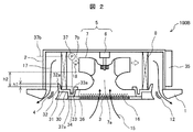
- FIG. 2 is a cross-sectional view showing an indoor unit 100B of an air conditioner according to a second embodiment of the present invention.
- This embodiment is different from the first embodiment in that a dug portion 34 dug further downward from the bottom surface 31 is provided on the upstream side of the heat exchanger 8 on the bottom surface 31 of the drain pan 30. .
- the electrical component box 35 is provided outside the housing 2. Since the electrical component box 35 is provided outside the housing 2, the shape of the bell mouth 36 is different from that of the first embodiment. In this embodiment, the centrifugal blower 5, the indoor heat exchanger 8, the drain pan 9, the bell mouth 10, and the filter 16 are arranged in a space surrounded by the casing 2 and the decorative panel 1 (inside the casing 2). The electrical component box 35 is disposed outside the housing 2.
- the upper end (upper edge portion) 33a of the wall surface 33 located on the upstream side of the heat exchanger 8 is the upper end of the wall surface 32 located on the downstream side of the heat exchanger 8.
- the upper end 33a of the wall surface 33 located on the lower side (lower position) of the (upper edge) 32a and located on the upstream side of the heat exchanger 8 is lower (lower position) than the lower end of the discharge port 7b of the centrifugal fan 7. ).
- the upper end 33a of the wall surface 33 and the upper end 32a of the wall surface 32 are separated by a distance h1 in the height direction.
- the lower end of the discharge port 7b of the centrifugal fan 7 and the upper end 33a of the wall surface 33 are separated by a distance h2 in the height direction.
- the digging portion 34 is provided on the upstream side of the heat exchanger 8 of the drain pan 30 to ensure the water retention amount of the drain pan 30.
- the downstream side of the heat exchanger 8 of the drain pan 30 constitutes an air blowing channel, it is difficult to provide a dug portion.
- the upstream side of the heat exchanger 8 is a dead water area of the fan suction port, even if the digging portion 34 is provided, the air flow is not adversely affected.
- the electrical component box 35 outside the housing 2, it is possible to provide the digging portion 34 in the portion where the electrical component box 11 is provided in the first embodiment, thereby further securing the water retention amount. can do.
- the digging portion has a part of the drain pan as shown in the first embodiment, and an electrical component box 11 is provided in this portion as in the first embodiment, and the grill It is also possible to adopt a structure that allows maintenance of the electrical component box 11 by removing. Furthermore, it is possible to provide a part or all of the dug portion 34 on the downstream side of the heat exchanger 8 by devising such as increasing the size of the product. Further, in the indoor unit of the air conditioner having such a structure, a drain pump 37 for discharging condensed water to the outside of the machine is provided, and the suction port 37a of the drain pump 37 is located at the same height as the digging portion 34.
- opening the suction port 37a of the drain pump 37 inside the digging portion 34 is desirable for efficient drain water discharge.
- the drain pump 37 may be provided in the first embodiment described above, or in a third embodiment and a fourth embodiment described later.
- the suction port 37a of the drain pump 37 is opened inside the dug portions 44 and 54 as in the present embodiment. Is desirable.
- the condensed water pumped up by the drain pump 37 is discharged out of the machine through the drain pipe 37b.
- FIG. 3 is a cross-sectional view showing an indoor unit 100C of an air conditioner according to a third embodiment of the present invention.
- the centrifugal blower 5, the indoor heat exchanger 8, the drain pan 40, the bell mouth 45, and the filter 16 are disposed in a space surrounded by the casing 2 and the decorative panel 1 (inside the casing 2).
- the electrical component box 35 is disposed outside the housing 2.
- the electrical component box 35 may be disposed inside the housing 2 as in the first embodiment.
- the present embodiment is different from the first and second embodiments in that the upper end 43a of the wall surface 43 located on the upstream side of the heat exchanger 8 of the drain pan 40 is lower (lower than the lower end of the heat exchanger 8). Position).
- the upper end (upper edge portion) 43a of the wall surface 43 located on the upstream side of the heat exchanger 8 is lower than the upper end (upper edge portion) 42a of the wall surface 42 located on the downstream side of the heat exchanger 8.
- the upper end 43a of the wall surface 43 located at the (low position) and upstream of the heat exchanger 8 is located below (lower position) than the lower end of the discharge port 7b of the centrifugal fan 7.
- the upper end 43a of the wall surface 43 and the upper end 42a of the wall surface 42 are separated by a distance h5 in the height direction.
- the lower end of the discharge port 7b of the centrifugal fan 7 and the upper end 43a of the wall surface 43 are separated by a distance h6 in the height direction.
- H5 and H6 in this embodiment are in a relationship of h5> h1 and h6> h2 with respect to h1 and h2 in the first embodiment. Moreover, the upper end 43a of the wall surface 43 and the lower end of the heat exchanger 8 are separated by a distance h7 in the height direction.
- the wall 43 on the upstream side of the heat exchanger 8 of the drain pan 40 is disposed so as to block the heat exchanger 8, so that the flow of air flowing into the heat exchanger 8 is hindered and becomes a ventilation resistance. End up. Therefore, in the present embodiment, the upstream wall surface 43 of the heat exchanger 8 is configured not to block the heat exchanger 8, thereby preventing ventilation resistance.
- a heat exchanging portion 44 that is dug further downward from the bottom surface 41 is provided on the upstream side of the heat exchanger 8 on the bottom surface 41 of the drain pan 40. Condensed water can be retained even if the upstream wall 43 is lowered.
- the height of the bell mouth 45 is higher than that of the first and second embodiments. Is also getting bigger.
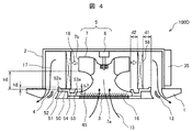
- FIG. 4 is a cross-sectional view showing an indoor unit 100D of an air conditioner according to a fourth embodiment of the present invention.
- the centrifugal fan 5, the indoor heat exchanger 58, the drain pan 50, the bell mouth 45, and the filter 16 are arranged in a space surrounded by the casing 2 and the decorative panel 1 (inside the casing 2).
- the electrical component box 35 is disposed outside the housing 2.
- the electrical component box 35 may be disposed inside the housing 2 as in the first embodiment.
- This embodiment differs from the third embodiment in that the distance d1 in the horizontal direction between the wall surface 52 and the heat exchanger 58 on the downstream side with respect to the heat exchanger 8 of the drain pan 50 is different from that of the heat exchanger 8. In other words, the distance between the upstream wall surface 53 and the heat exchanger 58 is greater than the distance d2 in the horizontal direction.
- the wall surface 52 on the downstream side of the heat exchanger 8 of the drain pan 50 retains the dew condensation water generated in the heat exchanger 8 and has a function of preventing the dew condensation generated in the heat exchanger 8 from jumping out to the outside by air blowing. .
- the dew condensation water is retained in the dug portion 54 provided on the upstream side with respect to the heat exchanger 8 and the distance d1 between the heat exchanger 58 and the wall surface 52 on the downstream side of the heat exchanger 8 is increased. For this reason, even if the height of the wall surface 52 on the downstream side of the heat exchanger 8 is lowered, it is possible to prevent the condensation generated in the heat exchanger 58 from blowing out to the outside due to the blowing. Further, by lowering the wall surface 52 on the downstream side of the heat exchanger 8, the air blown out from the heat exchanger 58 is not obstructed by the wall surface 52 on the downstream side of the heat exchanger 8, and the ventilation resistance can be reduced. .
- the positional relationship in the height direction between the wall surfaces 52 and 53 of the present embodiment and the discharge port 7b of the centrifugal fan 7 is configured as follows.
- the upper end (upper edge portion) 53a of the wall surface 43 located on the upstream side of the heat exchanger 58 is positioned lower (lower position) than the upper end (upper edge portion) 52a of the wall surface 52 located on the downstream side of the heat exchanger 58.
- the upper end 53a of the wall surface 53 located on the upstream side of the heat exchanger 58 is located below (lower position) than the lower end of the discharge port 7b of the centrifugal fan 7.
- the upper end 53a of the wall surface 53 and the upper end 52a of the wall surface 52 are separated by a distance h8 in the height direction.
- the lower end of the discharge port 7b of the centrifugal fan 7 and the upper end 53a of the wall surface 53 are separated by a distance h6 in the height direction.
- the upper end 53a of the wall surface 53 and the lower end of the heat exchanger 58 are separated by a distance h7 in the height direction. That is, the distance in the height direction between the lower end of the discharge port 7b of the centrifugal fan 7 and the upper end 53a of the wall surface 53 is the same as that of the third embodiment.
- the distance in the height direction between the upper end 53a of the wall surface 53 and the lower end of the heat exchanger 58 is also the same as that of the third embodiment.
- the distance relationship in the horizontal direction among the wall surface 52, the heat exchanger 58, and the wall surface 53 described in the present embodiment is also applicable to the first embodiment and the second embodiment.
- the thickness of the wall surfaces 23, 33, 43, 53 on the upstream side with respect to the heat exchangers 8, 58 of the drain pans 9, 30, 40, 50 is set to the heat exchangers 8, 58. Since the distance between the drain pans 9, 30, 40, 50 and the centrifugal blower 5 can be further increased by making the wall thickness 22, 32, 42, 52 on the downstream side thinner, it is advantageous for noise reduction. .
- the present Example has demonstrated the ceiling-embedded cassette type indoor unit which provided the blower outlet around the housing
- the present invention can also be applied to an indoor unit suspended from the indoor unit.
- the present invention can be applied in common to indoor units of a type that includes a centrifugal fan and is provided with a heat exchanger around or around the periphery thereof.
- this invention is not limited to each above-mentioned Example, Various modifications are included.
- the above-described embodiments have been described in detail for easy understanding of the present invention, and are not necessarily limited to those having all the configurations.
- a part of the configuration of one embodiment can be replaced with the configuration of another embodiment, and the configuration of another embodiment can be added to the configuration of one embodiment.
Abstract
Description
前記ドレンパンは、前記熱交換器に対して上流側に位置する前記壁面部の上端が前記熱交換器に対して下流側に位置する前記壁面部の上端よりも低く形成される。
Claims (8)
- 室内の空気を機内に吸い込む室内機吸込口と、前記室内機吸込口から吸い込んだ空気を周囲に吐出する遠心送風機と、前記遠心送風機の吐出側に設けられ空気を冷却または加熱する熱交換器と、前記熱交換器の下流側に設けられ空気を吹き出す吹出口と、前記熱交換器の下部に設けられ前記熱交換器で生じる結露水を受けるドレンパンとを備え、前記ドレンパンは前記熱交換器に対して上流側に位置する端部と下流側に位置する端部とからそれぞれ上方に立ち上がる壁面部を有し、前記遠心送風機の吐出口の下端を前記ドレンパンの前記熱交換器に対して上流側に位置する前記壁面部の上端よりも高い位置に設けた空気調和機の室内機において、
前記ドレンパンは、前記熱交換器に対して上流側に位置する前記壁面部の上端が前記熱交換器に対して下流側に位置する前記壁面部の上端よりも低く形成されたことを特徴とする空気調和機の室内機。 - 請求項1に記載の空気調和機の室内機において、
前記ドレンパンは、前記熱交換器に対して上流側に位置する壁面部と下流側に位置する壁面部との間の底面に、底面から更に下方に掘り込んだ掘り込み部が設けられたことを特徴とする空気調和機の室内機。 - 請求項2に記載の空気調和機の室内機において、
前記掘り込み部は前記熱交換器に対して上流側に設けられたことを特徴とする空気調和機の室内機。 - 請求項2に記載の空気調和機の室内機において、
ドレン水を機外に排出するためのドレンポンプを備えるとともに、前記ドレンポンプの吸入口を前記掘り込み部に設けたことを特徴とする空気調和機の室内機。 - 請求項1に記載の空気調和機の室内機において、
前記室内機吸込口を中心部に有すると共に、前記室内機吸込口の周囲に前記吹出口を有する化粧パネルと、前記化粧パネルに接続された筐体とを備え、
前記筐体の内側に前記遠心送風機と前記熱交換器と前記ドレンパンとを配置し、
室内機を制御するための制御基板を内蔵した電気品箱を筐体の外側に設けたことを特徴とする空気調和機の室内機。 - 請求項2に記載の空気調和機の室内機において、
前記ドレンパンの前記熱交換器に対して上流側に位置する壁面部の上端は、熱交換器の下端よりも下方に位置することを特徴とする空気調和機の室内機。 - 請求項1に記載の空気調和機の室内機において、
前記ドレンパンの前記熱交換器に対して上流側に位置する壁面部の厚さが、前記ドレンパンの前記熱交換器に対して下流側に位置する壁面部の厚さよりも薄いことを特徴とする空気調和機の室内機。 - 請求項1に記載の空気調和機の室内機において、
前記ドレンパンの前記熱交換器に対して上流側に位置する壁面部と前記熱交換器との距離よりも、前記ドレンパンの前記熱交換器に対して下流側に位置する壁面部と前記熱交換器との距離の方を大きくしたことを特徴とする空気調和機の室内機。
Priority Applications (5)
| Application Number | Priority Date | Filing Date | Title |
|---|---|---|---|
| US15/518,012 US20170299201A1 (en) | 2014-11-28 | 2014-11-28 | Indoor unit for air conditioner |
| PCT/JP2014/081500 WO2016084216A1 (ja) | 2014-11-28 | 2014-11-28 | 空気調和機の室内機 |
| JP2016561180A JPWO2016084216A1 (ja) | 2014-11-28 | 2014-11-28 | 空気調和機の室内機 |
| EP14906932.0A EP3225934A4 (en) | 2014-11-28 | 2014-11-28 | Indoor unit for air conditioner |
| CN201480083311.7A CN107076455A (zh) | 2014-11-28 | 2014-11-28 | 空调机的室内机 |
Applications Claiming Priority (1)
| Application Number | Priority Date | Filing Date | Title |
|---|---|---|---|
| PCT/JP2014/081500 WO2016084216A1 (ja) | 2014-11-28 | 2014-11-28 | 空気調和機の室内機 |
Publications (1)
| Publication Number | Publication Date |
|---|---|
| WO2016084216A1 true WO2016084216A1 (ja) | 2016-06-02 |
Family
ID=56073831
Family Applications (1)
| Application Number | Title | Priority Date | Filing Date |
|---|---|---|---|
| PCT/JP2014/081500 WO2016084216A1 (ja) | 2014-11-28 | 2014-11-28 | 空気調和機の室内機 |
Country Status (5)
| Country | Link |
|---|---|
| US (1) | US20170299201A1 (ja) |
| EP (1) | EP3225934A4 (ja) |
| JP (1) | JPWO2016084216A1 (ja) |
| CN (1) | CN107076455A (ja) |
| WO (1) | WO2016084216A1 (ja) |
Cited By (1)
| Publication number | Priority date | Publication date | Assignee | Title |
|---|---|---|---|---|
| WO2019150691A1 (ja) * | 2018-01-30 | 2019-08-08 | 三菱重工サーマルシステムズ株式会社 | 天井埋込み型空気調和機 |
Families Citing this family (2)
| Publication number | Priority date | Publication date | Assignee | Title |
|---|---|---|---|---|
| JP6369684B2 (ja) * | 2014-10-10 | 2018-08-08 | 株式会社富士通ゼネラル | 天井埋込型空気調和機 |
| CN109631163A (zh) * | 2018-12-19 | 2019-04-16 | 青岛海尔空调电子有限公司 | 风管机 |
Citations (6)
| Publication number | Priority date | Publication date | Assignee | Title |
|---|---|---|---|---|
| JPH04136434U (ja) * | 1991-05-31 | 1992-12-18 | 三菱重工業株式会社 | 天井埋込型空気調和機 |
| JPH0886462A (ja) * | 1994-09-20 | 1996-04-02 | Hitachi Ltd | 空気調和機 |
| JPH109665A (ja) * | 1996-06-19 | 1998-01-16 | Toshiba Corp | 天井吊り形空気調和機 |
| JP2000111137A (ja) * | 1998-09-30 | 2000-04-18 | Fujitsu General Ltd | 天井埋込型空気調和機 |
| JP2000283548A (ja) * | 1999-03-29 | 2000-10-13 | Sanyo Electric Co Ltd | ビルトイン型空気調和装置 |
| JP2013164219A (ja) * | 2012-02-10 | 2013-08-22 | Daikin Industries Ltd | 室内機 |
Family Cites Families (13)
| Publication number | Priority date | Publication date | Assignee | Title |
|---|---|---|---|---|
| JPS62178822A (ja) * | 1986-02-03 | 1987-08-05 | Matsushita Refrig Co | 空気調和機 |
| JP3593418B2 (ja) * | 1996-07-03 | 2004-11-24 | 東芝キヤリア株式会社 | 天井カセット形空気調和機 |
| US6598413B2 (en) * | 1999-01-25 | 2003-07-29 | Mitsubishi Denki Kabushiki Kaisha | Ceiling embedded-type air conditioner |
| JP3408983B2 (ja) * | 1999-01-25 | 2003-05-19 | 三菱電機株式会社 | 天井埋込型空気調和機 |
| KR100402195B1 (ko) * | 2000-01-28 | 2003-10-22 | 도시바 캐리어 가부시키 가이샤 | 천장에 장착되는 카세트형 공기조화기 |
| JP2002139230A (ja) * | 2000-11-02 | 2002-05-17 | Hitachi Ltd | 空気調和機の室内ユニット |
| US20070209373A1 (en) * | 2004-04-15 | 2007-09-13 | Daikin Industries, Ltd. | Air Conditioner |
| JP4252530B2 (ja) * | 2004-12-13 | 2009-04-08 | ダイキン工業株式会社 | 空気調和機のドレン水静菌構造 |
| KR100972273B1 (ko) * | 2007-07-25 | 2010-07-23 | 산요덴키가부시키가이샤 | 천장 매립형 공기 조화 장치의 실내기 |
| JP5247784B2 (ja) * | 2010-10-04 | 2013-07-24 | 三菱電機株式会社 | 空気調和機 |
| JP5738781B2 (ja) * | 2012-02-10 | 2015-06-24 | ダイキン工業株式会社 | 空気調和装置 |
| JP2015081692A (ja) * | 2013-10-21 | 2015-04-27 | 日立アプライアンス株式会社 | 空気調和機の室内機 |
| JP2016142431A (ja) * | 2015-01-30 | 2016-08-08 | ジョンソンコントロールズ ヒタチ エア コンディショニング テクノロジー(ホンコン)リミテッド | 空気調和機 |
-
2014
- 2014-11-28 WO PCT/JP2014/081500 patent/WO2016084216A1/ja active Application Filing
- 2014-11-28 JP JP2016561180A patent/JPWO2016084216A1/ja active Pending
- 2014-11-28 CN CN201480083311.7A patent/CN107076455A/zh not_active Withdrawn
- 2014-11-28 US US15/518,012 patent/US20170299201A1/en not_active Abandoned
- 2014-11-28 EP EP14906932.0A patent/EP3225934A4/en not_active Withdrawn
Patent Citations (6)
| Publication number | Priority date | Publication date | Assignee | Title |
|---|---|---|---|---|
| JPH04136434U (ja) * | 1991-05-31 | 1992-12-18 | 三菱重工業株式会社 | 天井埋込型空気調和機 |
| JPH0886462A (ja) * | 1994-09-20 | 1996-04-02 | Hitachi Ltd | 空気調和機 |
| JPH109665A (ja) * | 1996-06-19 | 1998-01-16 | Toshiba Corp | 天井吊り形空気調和機 |
| JP2000111137A (ja) * | 1998-09-30 | 2000-04-18 | Fujitsu General Ltd | 天井埋込型空気調和機 |
| JP2000283548A (ja) * | 1999-03-29 | 2000-10-13 | Sanyo Electric Co Ltd | ビルトイン型空気調和装置 |
| JP2013164219A (ja) * | 2012-02-10 | 2013-08-22 | Daikin Industries Ltd | 室内機 |
Non-Patent Citations (1)
| Title |
|---|
| See also references of EP3225934A4 * |
Cited By (2)
| Publication number | Priority date | Publication date | Assignee | Title |
|---|---|---|---|---|
| WO2019150691A1 (ja) * | 2018-01-30 | 2019-08-08 | 三菱重工サーマルシステムズ株式会社 | 天井埋込み型空気調和機 |
| JP2019132475A (ja) * | 2018-01-30 | 2019-08-08 | 三菱重工サーマルシステムズ株式会社 | 天井埋込み型空気調和機 |
Also Published As
| Publication number | Publication date |
|---|---|
| EP3225934A4 (en) | 2018-08-08 |
| JPWO2016084216A1 (ja) | 2017-05-25 |
| EP3225934A1 (en) | 2017-10-04 |
| US20170299201A1 (en) | 2017-10-19 |
| CN107076455A (zh) | 2017-08-18 |
Similar Documents
| Publication | Publication Date | Title |
|---|---|---|
| US7461518B2 (en) | Fan and air conditioner | |
| US20080034775A1 (en) | Air conditioner | |
| JP2011111998A (ja) | 送風機のベルマウス構造 | |
| WO2016084216A1 (ja) | 空気調和機の室内機 | |
| JPWO2014181398A1 (ja) | 空気調和機の室内機、及び空気調和機 | |
| US20180195790A1 (en) | Indoor unit for air conditioner | |
| JP6139669B2 (ja) | 空気調和機 | |
| KR101918225B1 (ko) | 실내기 | |
| JP5860752B2 (ja) | 空気調和機 | |
| JP6521249B2 (ja) | 天井埋込型空気調和機 | |
| JP2017048954A (ja) | 空気調和機の室内機 | |
| JP2013249994A (ja) | 天井埋込ダクト型室内ユニット | |
| JP2017215091A (ja) | 空気調和機の室内機 | |
| KR101419941B1 (ko) | 천장형 공기 조화기의 실내기 | |
| JP2015068561A (ja) | 空気調和機の室内機 | |
| KR100829191B1 (ko) | 공기조화기용 실외기 | |
| JP6340694B2 (ja) | 送風装置 | |
| KR102522048B1 (ko) | 천장형 공기조화기 | |
| WO2018029878A1 (ja) | 室内機および空気調和機 | |
| JP2007263430A (ja) | 空気調和機 | |
| JP2014005976A (ja) | 空気調和機の室内機 | |
| KR101419944B1 (ko) | 공기 조화기의 실내기 | |
| JP6217920B2 (ja) | 空気調和機の天井埋込型室内機 | |
| JP2018179384A (ja) | 空気調和機の室内機 | |
| JP2013108684A (ja) | 空気調和機の室内機 |
Legal Events
| Date | Code | Title | Description |
|---|---|---|---|
| 121 | Ep: the epo has been informed by wipo that ep was designated in this application |
Ref document number: 14906932 Country of ref document: EP Kind code of ref document: A1 |
|
| ENP | Entry into the national phase |
Ref document number: 2016561180 Country of ref document: JP Kind code of ref document: A |
|
| WWE | Wipo information: entry into national phase |
Ref document number: 15518012 Country of ref document: US |
|
| REEP | Request for entry into the european phase |
Ref document number: 2014906932 Country of ref document: EP |
|
| NENP | Non-entry into the national phase |
Ref country code: DE |