WO2016072166A1 - 熱式空気流量計 - Google Patents
熱式空気流量計 Download PDFInfo
- Publication number
- WO2016072166A1 WO2016072166A1 PCT/JP2015/076833 JP2015076833W WO2016072166A1 WO 2016072166 A1 WO2016072166 A1 WO 2016072166A1 JP 2015076833 W JP2015076833 W JP 2015076833W WO 2016072166 A1 WO2016072166 A1 WO 2016072166A1
- Authority
- WO
- WIPO (PCT)
- Prior art keywords
- thermal air
- flow meter
- air flow
- substrate
- filler
- Prior art date
Links
Images


Classifications
-
- G—PHYSICS
- G01—MEASURING; TESTING
- G01F—MEASURING VOLUME, VOLUME FLOW, MASS FLOW OR LIQUID LEVEL; METERING BY VOLUME
- G01F1/00—Measuring the volume flow or mass flow of fluid or fluent solid material wherein the fluid passes through a meter in a continuous flow
- G01F1/68—Measuring the volume flow or mass flow of fluid or fluent solid material wherein the fluid passes through a meter in a continuous flow by using thermal effects
- G01F1/696—Circuits therefor, e.g. constant-current flow meters
-
- F—MECHANICAL ENGINEERING; LIGHTING; HEATING; WEAPONS; BLASTING
- F02—COMBUSTION ENGINES; HOT-GAS OR COMBUSTION-PRODUCT ENGINE PLANTS
- F02M—SUPPLYING COMBUSTION ENGINES IN GENERAL WITH COMBUSTIBLE MIXTURES OR CONSTITUENTS THEREOF
- F02M35/00—Combustion-air cleaners, air intakes, intake silencers, or induction systems specially adapted for, or arranged on, internal-combustion engines
- F02M35/10—Air intakes; Induction systems
- F02M35/10373—Sensors for intake systems
- F02M35/10386—Sensors for intake systems for flow rate
-
- G—PHYSICS
- G01—MEASURING; TESTING
- G01F—MEASURING VOLUME, VOLUME FLOW, MASS FLOW OR LIQUID LEVEL; METERING BY VOLUME
- G01F1/00—Measuring the volume flow or mass flow of fluid or fluent solid material wherein the fluid passes through a meter in a continuous flow
- G01F1/68—Measuring the volume flow or mass flow of fluid or fluent solid material wherein the fluid passes through a meter in a continuous flow by using thermal effects
- G01F1/684—Structural arrangements; Mounting of elements, e.g. in relation to fluid flow
- G01F1/6842—Structural arrangements; Mounting of elements, e.g. in relation to fluid flow with means for influencing the fluid flow
-
- G—PHYSICS
- G01—MEASURING; TESTING
- G01F—MEASURING VOLUME, VOLUME FLOW, MASS FLOW OR LIQUID LEVEL; METERING BY VOLUME
- G01F15/00—Details of, or accessories for, apparatus of groups G01F1/00 - G01F13/00 insofar as such details or appliances are not adapted to particular types of such apparatus
- G01F15/006—Details of, or accessories for, apparatus of groups G01F1/00 - G01F13/00 insofar as such details or appliances are not adapted to particular types of such apparatus characterised by the use of a particular material, e.g. anti-corrosive material
-
- G—PHYSICS
- G01—MEASURING; TESTING
- G01F—MEASURING VOLUME, VOLUME FLOW, MASS FLOW OR LIQUID LEVEL; METERING BY VOLUME
- G01F15/00—Details of, or accessories for, apparatus of groups G01F1/00 - G01F13/00 insofar as such details or appliances are not adapted to particular types of such apparatus
- G01F15/02—Compensating or correcting for variations in pressure, density or temperature
Definitions
- the present invention relates to a flow meter that measures the flow rate of a gas to be measured, and more particularly to a thermal air flow meter that measures the intake air amount of an internal combustion engine.
- a thermal air flow meter that measures the gas flow rate has a flow rate detection unit for measuring the flow rate, and measures the gas flow rate by transferring heat between the flow rate detection unit and the gas to be measured. Is configured to do.
- the flow rate measured by the thermal air flow meter is widely used as an important control parameter in various apparatuses.
- a feature of the thermal air flow meter is that a gas flow rate, for example, a mass flow rate can be measured with relatively high accuracy compared to other types of flow meters.
- a thermal air flow meter for measuring the amount of intake air led to an internal combustion engine includes a sub-passage that takes in a part of the intake air amount and a flow rate detection unit disposed in the sub-passage, and the flow rate detection unit is a gas to be measured.
- the state of the gas to be measured flowing through the sub-passage is measured by performing heat transfer between and the electric signal, and an electric signal representing the amount of intake air guided to the internal combustion engine is output.
- a housing including a sub-passage in which a hole for fitting a flow rate detection unit is molded is manufactured in advance, and a sensor assembly including a flow rate detection unit is manufactured separately from the housing. Then, the sensor assembly is fixed to the housing in a state where the flow rate detection unit is inserted into the hole of the sub passage.
- the gap between the hole of the sub passage and the flow rate detection unit and the gap of the fitting portion of the sensor assembly to the housing are filled with elastic adhesive, and the difference in linear expansion coefficient between each other is determined by the elastic force of the adhesive. Absorbs.
- An object of the present invention is to provide a thermal air flow meter with high measurement accuracy.
- a thermal air flow meter of the present invention includes, for example, a sub-passage that takes in a part of a fluid to be measured, and a sensor chip that is disposed in the sub-passage and measures the flow rate of the fluid to be measured.
- the sensor assembly 10 is formed by mounting an electronic component 3 and a sensor chip 2 on a substrate 1.
- the substrate 1 may be a ceramic substrate or a printed substrate.
- the electronic component 3 is, for example, an LSI, and a resistor 7 is disposed in the electronic component 3, and this resistor 7 is used, for example, as a reference oscillator (clock) or an A / D converter.
- the substrate 1 and the sensor chip 2 and the substrate 1 and the electronic component 3 are electrically connected using solder or bonding wires.
- the air 26 passes through the flow rate detection unit of the sensor chip 2 from the direction of the arrow in FIG.
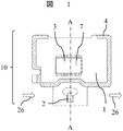
- FIG. 2 is a plan view when the sensor assembly 10 is mounted on the housing 5 including the sub passage 12.
- the housing 5 includes a sub-passage 12 for guiding the air flowing through the main passage to the sensor chip 2, and the housing 5 made of the first resin and the sensor assembly 10 are integrally molded, and the sensor assembly 10 is shown in FIG. It is fixed to the housing 5 in a fixing area 4 indicated by oblique lines.
- the first resin used for the housing 5 is, for example, a thermoplastic resin.
- the sensor chip 2 having the flow rate detection unit needs to measure the air flow rate, and thus is disposed in the sub-passage 12.
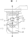
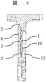
- FIG. 3 is a plan view of the thermal air flow meter after sealing with the filler 6, and FIG. 4 is a cross-sectional view taken along the line CC in FIG.
- the filler 6 is filled into the space formed by the sensor assembly 10 and the housing 5 so as to cover the electronic component 3.
- an epoxy resin is used as the filler.
- the thermal air flow meter is exposed to an atmosphere of exhaust gas, gasoline, salt water or the like because it is used for measuring the flow rate of a vehicle equipped with an internal combustion engine, for example.
- a flow meter can be provided.
- FIG. 5 is a cross-sectional view of the thermal air flow meter when a temperature change is given.
- the thermal air flow meter and the substrate 1 have a linear expansion coefficient difference between the substrate 1 and the filler 6 or a resin contraction difference as shown in FIG. Bending deformation occurs as shown.
- stress (strain) is also generated in the resistor 7 in the electronic component 3.
- stress (strain) is generated in the resistor 7, the resistance value changes due to the piezo effect, and the output characteristics of the LSI 3 change, which affects the measurement accuracy of the air flow rate.
- FIG. 5 is a cross-sectional view of the thermal air flow meter when a temperature change is given.
- FIG. 6 shows the relationship between the ratio of the linear expansion coefficient and the Young's modulus between the substrate 1 and the filler 6 and the flow characteristic variation caused by the thermal stress of the resistor 7 in the electronic component 3 by stress analysis.
- the vertical axis (y-axis) in FIG. 6 is the ratio of Young's modulus between the substrate 1 and the filler 6, and the horizontal axis (x-axis) is the ratio of the linear expansion coefficient between the substrate 1 and the filler 6. Both are dimensionless.
- the relationship between the linear expansion coefficient and Young's modulus ratio of the substrate 1 and the filler 6 when the flow characteristic fluctuation due to the thermal stress of the resistor 7 becomes ⁇ 1.0%, ⁇ 1.5%, ⁇ 2.0%, calculated by stress analysis. Plotted in FIG.
- FIG. 6 shows that the flow characteristic variation increases as the ratio between the linear expansion coefficient and the Young's modulus increases.
- the ratio of the linear expansion coefficient and the Young's modulus of the substrate 1 and the filler 6 are set within a predetermined region indicated by the hatched portion in FIG. That is, when the ratio of the linear expansion coefficient between the substrate 1 and the filler 6 is x and the ratio of the Young's modulus is y, the relationship y ⁇ 0.4x ⁇ 0.9 is established. Thereby, the resistance value fluctuation
- FIG. 7 is a plan view of a thermal air flow meter when the sensor assembly 10 is fixed to the housing 5, and FIG. 8 is a bottom view.
- the electronic component is, for example, a thermistor, a microcomputer, a pressure sensor, or a humidity sensor.
- the sensor assembly 10 and a connector 21 installed in the housing are electrically connected using a bonding wire 20.
- the material of the bonding wire is, for example, Al, Au, or Cu.
- FIG. 9 shows a plan view of the thermal air flow meter after sealing the filler 6. Needless to say, the structure shown in FIG. Furthermore, since the bonding wire 20 is protected by the filler 6, deformation of the bonding wire 20 due to vibration can be suppressed, and a more reliable flow meter can be provided.
- a different configuration from the previous embodiment is that a cover 8 is installed in the housing 5 to form a sub-passage, and a hole is provided in at least a part of the cover 8.
- the filler 6 is exposed to the main passage, and the heat dissipation effect of the filler is increased, so that the temperature rise due to heat generation of the electronic components 3 and 13 to 16 can be further reduced.
- the structure in which the cover 8 and the filler are brought into close contact with each other also improves the thermal conductivity, increases the heat radiation effect by the air flow in the main passage, and enables higher accuracy.
- the difference from the previous embodiment is that, as shown in FIG. 11, the relationship between the ratio of the linear expansion coefficient and the Young's modulus of the substrate 1 and the filler 6 used in the thermal air flow meter is indicated by the shaded area in FIG. It is a point that is inside. That is, if the ratio of Young's modulus between the substrate 1 and the filler 6 is y, the relationship is y ⁇ 0.1.
- the electronic components 3 and 13 to 16 shown in FIGS. 7 and 8 are electrically connected to the substrate 1 using solder or bonding wires. Furthermore, the bonding wire 20 is used to electrically connect the substrate 1 and the connector 21 installed in the housing.
Abstract
熱式空気流量計の計測精度を向上させること。 被計測流体の一部を取り込む副通路と、前記副通路に配置され前記被計測流体の流量を計測するセンサチップと、前記センサチップにより検出した流体流量を電気信号に変換し内部に抵抗体を有する電子部品と、前記センサチップ及び前記電子部品を搭載する基板と、を有し、前記基板は、前記電子部品が搭載された側の面が充填材により覆われている。
Description
本発明は被測定気体の流量を計測する流量計に係り、特に、内燃機関の吸入空気量を計測する熱式空気流量計に関する。
気体流量を計測する熱式空気流量計は、流量を計測するための流量検出部を備え、前記流量検出部と計測対象である気体との間で熱伝達を行うことにより、気体の流量を計測するように構成されている。熱式空気流量計が計測する流量は、様々な装置において重要な制御パラメータとして広く使用されている。熱式空気流量計の特徴は、他方式の流量計に比べ相対的に高い精度で気体流量、例えば質量流量を計測できることである。
しかし、さらなる気体流量の計測精度の向上が望まれている。例えば、内燃機関を搭載した車両では、省燃費の要望や排気ガス浄化の要望が非常に高い。これらの要望に応えるには、内燃機関の主要パラメータである吸入空気量を高い精度で計測することが求められている。内燃機関に導かれる吸入空気量を計測する熱式空気流量計は、吸入空気量の一部を取り込む副通路と前記副通路に配置された流量検出部を備え、前記流量検出部が被計測気体との間で熱伝達を行うことにより、前記副通路を流れる被計測気体の状態を計測して、前記内燃機関に導かれる吸入空気量を表す電気信号を出力する。このような技術は、例えば特開2011-252796号公報(特許文献1)に開示されている。
特許文献1に記載の技術では、流量検出部を嵌め込むための孔が成型された副通路を備える筐体を予め樹脂で製造し、この筐体とは別に、流量検出部を備えるセンサアセンブリを製造し、次に前記副通路の孔に前記流量検出部を挿入した状態で、前記センサアセンブリを筐体に固定する。前記副通路の孔と流量検出部との間の隙間、およびセンサアセンブリの筐体への嵌め込み部分の隙間には、弾性接着剤が充填され、互いの線膨張係数差を接着剤の弾性力で吸収している。
しかし、このような構造では、流量検出部を含むセンサアセンブリを、副通路を含む筐体へ固定する際の位置ばらつきが大きくなる。すなわちセンサアセンブリと筐体に設けられた副通路との位置や角度が、接着剤の状態などにより簡単に変化する課題があった。このため従来の熱式空気流量計では、流量の検出精度をさらに向上することが難しかった。
副通路に対して流量検出部を正確に位置決めするには、流量検出部を含むセンサアセンブリを筐体形成と同時に固定することが有効となる。しかし、この場合には、部品間の線膨張係数差に起因してLSI内の抵抗に発生する熱応力が接着剤を使用する場合に比べて高く、さらには、電子部品の発熱により、温度補正の精度が低下するため、測定精度が低下するという課題があった。
本発明の目的は、計測精度の高い熱式空気流量計を提供することである。
上記目的を達成するために、本発明の熱式空気流量計は、例えば、被計測流体の一部を取り込む副通路と、前記副通路に配置され前記被計測流体の流量を計測するセンサチップと、前記センサチップにより検出した流体流量を電気信号に変換し内部に抵抗体を有する電子部品と、前記センサチップ及び前記電子部品を搭載する基板と、を有し、前記基板は、前記電子部品が搭載された側の面が充填材により覆われた構成からなる。
本発明によれば、計測精度の高い熱式空気流量計を提供することが可能となる。
以下、本発明の実施例について図を用いて説明する。
まず初めに熱式空気流量計の第1実施例について説明する。
図1に示すように、センサアセンブリ10は電子部品3、センサチップ2を基板1上に実装することで形成される。なお、基板1として、セラミック基板を用いてもプリント基板を用いても構わない。また、電子部品3は例えばLSIであり、電子部品3内には抵抗体7が配置され、この抵抗体7は例えば基準発信器(クロック)やA/D変換器などに用いられる。基板1とセンサチップ2の間、及び基板1と電子部品3の間は、はんだもしくはボンディングワイヤを用いて電気的に結線される。流量検出時は、図1の矢印方向もしくは反対方向から空気26がセンサチップ2の流量検出部を通過することで流量を測定する。
図2は副通路12を含む筐体5にセンサアセンブリ10を実装したときの平面図である。上記筐体5は主通路を流れる空気をセンサチップ2に導くための副通路12を備えており、第1樹脂からなる筐体5とセンサアセンブリ10が一体成型され、センサアセンブリ10は図1の斜線で示した固定領域4で筐体5に固定される。筐体5に用いる第1樹脂は例えば熱可塑性樹脂である。この際、流量検出部を有するセンサチップ2は空気流量を測定する必要があるため、上記副通路12中に配置される。
図3は充填材6で封止後の熱式空気流量計の平面図、図4は図3上のC-C断面図である。図3、図4に示すとおり、充填材6はセンサアセンブリ10と筐体5からなる空間に対し、電子部品3を覆うように充填される。充填材は例えばエポキシ樹脂が用いられる。
次に、上記第1実施例による作用効果について説明する。流量測定時は、電子部品3内の抵抗体7に電圧が印加されるため、抵抗体7が発熱する。この発熱により、熱式空気流量計の温度が上昇し、環境温度との差が大きくなるため、流量測定精度が低下する。したがって、抵抗体7の発熱による熱式空気流量計の温度上昇を抑制する必要がある。図3に示すように電子部品3を充填材6で覆うことにより、熱伝導性が向上する。そのため、電子部品3が放熱しやすくなり、温度上昇を抑制することができる。さらに、熱式空気流量計は例えば内燃機関を搭載した車両の流量測定のために用いるため、排気ガス、ガソリン、塩水等の雰囲気中に晒される。センサアセンブリ10に搭載した電子部品3を充填材6で覆うことにより、電子部品3が上記雰囲気中に暴露することを防ぐため、電子部品3の特性変動を防止でき、より高精度な熱式空気流量計を提供できる。
次に、本発明の第2実施例について図5、図6を用いて説明する。
図5は、温度変化を与えたときの熱式空気流量計の断面図である。センサアセンブリ10上の電子部品3を充填材6により覆うと、熱式空気流量計及び基板1には、基板1と充填材6の線膨張係数差、もしくは樹脂収縮差に起因して図5に示すような曲げ変形が発生する。これにより、電子部品3内の抵抗体7にも応力(ひずみ)が発生する。抵抗体7に応力(ひずみ)が発生すると、ピエゾ効果によって抵抗値が変化し、LSI3の出力特性が変化するため、空気流量の測定精度に影響を及ぼす。図6は、基板1と充填材6の線膨張係数の比及びヤング率の比と、電子部品3内の抵抗体7の熱応力による流量特性変動の関係を応力解析により算出したものである。図6の縦軸(y軸)は基板1と充填材6のヤング率の比、横軸(x軸)は基板1と充填材6の線膨張係数の比であり、ともに無次元である。応力解析により算出した、抵抗体7の熱応力による流量特性変動が±1.0%,±1.5%、±2.0%となるときの基板1と充填材6の線膨張係数、ヤング率の比の関係を図6にプロットした。さらに、上記プロットを用いて、線膨張係数及びヤング率の比と流量特性変動の関係を累乗近似により求めた。図6より、線膨張係数及びヤング率の比を大きくするほど流量特性変動が大きくなることがわかる。
図5は、温度変化を与えたときの熱式空気流量計の断面図である。センサアセンブリ10上の電子部品3を充填材6により覆うと、熱式空気流量計及び基板1には、基板1と充填材6の線膨張係数差、もしくは樹脂収縮差に起因して図5に示すような曲げ変形が発生する。これにより、電子部品3内の抵抗体7にも応力(ひずみ)が発生する。抵抗体7に応力(ひずみ)が発生すると、ピエゾ効果によって抵抗値が変化し、LSI3の出力特性が変化するため、空気流量の測定精度に影響を及ぼす。図6は、基板1と充填材6の線膨張係数の比及びヤング率の比と、電子部品3内の抵抗体7の熱応力による流量特性変動の関係を応力解析により算出したものである。図6の縦軸(y軸)は基板1と充填材6のヤング率の比、横軸(x軸)は基板1と充填材6の線膨張係数の比であり、ともに無次元である。応力解析により算出した、抵抗体7の熱応力による流量特性変動が±1.0%,±1.5%、±2.0%となるときの基板1と充填材6の線膨張係数、ヤング率の比の関係を図6にプロットした。さらに、上記プロットを用いて、線膨張係数及びヤング率の比と流量特性変動の関係を累乗近似により求めた。図6より、線膨張係数及びヤング率の比を大きくするほど流量特性変動が大きくなることがわかる。
本実施例では、基板1と充填材6の線膨張係数の比及びヤング率の比が図6の斜線部で示す所定領域内となるようにした。すなわち、基板1と充填材6の線膨張係数の比をx、ヤング率の比をyとするとy<0.4x-0.9なる関係が成り立つようにした。これにより、温度変化時の抵抗体7の抵抗値変動を抑制することができ、流量特性変動を±1%以内に抑えることができる。流量検出精度の更なる高精度化が可能となる。
次に、本発明の第3実施例について図7~図9を用いて説明する。
図7はセンサアセンブリ10を筐体5に固定したときの熱式空気流量計の平面図、図8は底面図である。先の実施例と異なる構成は、図7、図8に示すように基板上に複数の電子部品13~16を設置している点である。電子部品は例えば、サーミスタやマイコン、圧力センサ、湿度センサである。図7に示すように、ボンディングワイヤ20を用いて、センサアセンブリ10と筐体に設置されたコネクタ21とを電気的に接続している。ボンディングワイヤの材質は、例えばAl、Au、Cuである。図9に充填材6を封止した後の熱式空気流量計の平面図を示す。図9に示す構造としても同等の作用効果を奏することは言うまでもない。更に、充填材6によりボンディングワイヤ20を保護するため、振動によるボンディングワイヤ20の変形を抑制することができ、より高信頼な流量計を提供できる。
図7はセンサアセンブリ10を筐体5に固定したときの熱式空気流量計の平面図、図8は底面図である。先の実施例と異なる構成は、図7、図8に示すように基板上に複数の電子部品13~16を設置している点である。電子部品は例えば、サーミスタやマイコン、圧力センサ、湿度センサである。図7に示すように、ボンディングワイヤ20を用いて、センサアセンブリ10と筐体に設置されたコネクタ21とを電気的に接続している。ボンディングワイヤの材質は、例えばAl、Au、Cuである。図9に充填材6を封止した後の熱式空気流量計の平面図を示す。図9に示す構造としても同等の作用効果を奏することは言うまでもない。更に、充填材6によりボンディングワイヤ20を保護するため、振動によるボンディングワイヤ20の変形を抑制することができ、より高信頼な流量計を提供できる。
次に、本発明の第4実施例について図10を用いて説明する。
先の実施例と異なる構成は、副通路形成のため筐体5にカバー8を設置し、カバー8の少なくとも1部に孔を設けている点である。これにより、充填材6が主通路に暴露された構造となり、充填材の放熱効果が高まるため、電子部品3、13~16の発熱による温度上昇をより低減することができる。また、カバー8と充填材を密着させる構造とすることによっても、熱伝導性がよくなり、主通路の空気流による放熱効果が高まり高精度化が可能となることは言うまでもない。
次に、本発明の第5実施例について図11を用いて説明する。
先の実施例と異なる点は、図11に示すように、熱式空気流量計に用いる基板1と充填材6の線膨張係数の比及びヤング率の比との関係を図11の斜線部領域内にしている点である。すなわち、基板1と充填材6のヤング率の比をyとすると、y<0.1なる関係とする。図7、図8に示した電子部品3、13~16は、はんだ、もしくはボンディングワイヤを用いて基板1と電気的に接続する。さらに、ボンディングワイヤ20を用いて基板1と筐体に設置されたコネクタ21を電気的に接続している。はんだやボンディングワイヤの熱変形に対する信頼性を高め、より高寿命とするためには、これらの接合材と充填材6との線膨張係数差を小さくすることが望ましい。図11の斜線部領域内とすることで、基板1と充填材6の線膨張係数の比に関わらず、抵抗値変動を±1%以下に抑制できる。したがって、はんだやボンディングワイヤの線膨張係数と充填材の線膨張係数の差を小さくし、且つ抵抗値変動を±1%以下に抑制できるため、より高信頼で高精度な流量計を提供できる。
1…基板、2…センサチップ、3…電子部品、4…固定領域、5…筐体、6…充填材、 7…抵抗体、8…カバー、10…センサアセンブリ、11…筐体、12…副通路、
13~16…電子部品、20…ボンディングワイヤ、21…コネクタ
13~16…電子部品、20…ボンディングワイヤ、21…コネクタ
Claims (13)
- 被計測流体の一部を取り込む副通路と、
前記副通路に配置され前記被計測流体の流量を計測するセンサチップと、
前記センサチップにより検出した流体流量を電気信号に変換し内部に抵抗体を有する電子部品と、
前記センサチップ及び前記電子部品を搭載する基板と、を有し、
前記基板は、前記電子部品が搭載された側の面が充填材により覆われていることを特徴とする熱式空気流量計。 - 請求項1に記載の熱式空気流量計において、
前記基板と前記充填材のヤング率及び線膨張係数が、前記基板と前記充填材のヤング率の比と、線膨張係数の比とで決まる所定領域範囲内にあることを特徴とする熱式空気流量計。 - 請求項2に記載の熱式空気流量計において、
前記所定領域は、前記抵抗体の抵抗値変動が所定範囲内であることを特徴とする熱式空気流量計。 - 請求項3に記載の熱式空気流量計において、
前記所定範囲は±1%であることを特徴とする熱式空気流量計。 - 請求項4に記載の熱式空気流量計において、
前記基板と前記充填材のヤング率の比をY、前記基板と前記充填材の線膨張係数の比をXとすると、Y<0.4X-0.9なる関係があることを特徴とする熱式空気流量計。 - 請求項1~5のいずれかに記載の熱式空気流量計において、
前記充填材の少なくとも一部が前記被計測流体に暴露していることを特徴とする熱式空気流量計。 - 請求項1~6のいずれかに記載の熱式空気流量計において、
前記筐体は、外部出力のためのコネクタを有し、前記コネクタと前記基板がワイヤボンディングにより電気的に接続することを特徴とする熱式空気流量計。 - 請求項1~7のいずれかに記載の熱式空気流量計において、
前記電子部品の少なくともひとつがワイヤボンディングもしくははんだにより前記基板と電気的に接続することを特徴とする熱式空気流量計。 - 請求項8に記載の熱式空気流量計において、
前記充填材と前記基板のヤング率が、前記充填材と前記基板のヤング率の比とできまる所定領域にあることを特徴とする熱式空気流量計。 - 請求項9に記載の熱式空気流量計において、
前記充填材と前記基板のヤング率の比とできまる前記所定領域は、前記充填材のヤング率をE1、前記基板のヤング率をE2とすると、E1/E2<0.1なる関係があることを特徴とする熱式空気流量計。 - 請求項1~10のいずれかに記載の熱式空気流量計において、
前記充填材は、エポキシ樹脂であることを特徴とする熱式空気流量計。 - 請求項1~11のいずれかに記載の熱式空気流量計において、
前記基板は、プリント基板であることを特徴とする熱式空気流量計。 - 請求項1~12のいずれかに記載の熱式空気流量計において、
前記筐体は、熱可塑性樹脂であることを特徴とする熱式空気流量計。
Priority Applications (3)
| Application Number | Priority Date | Filing Date | Title |
|---|---|---|---|
| EP15856909.5A EP3217153B1 (en) | 2014-11-06 | 2015-09-24 | Thermal air flow meter |
| US15/519,452 US10928232B2 (en) | 2014-11-06 | 2015-09-24 | Thermal air flow meter |
| CN201580057740.1A CN107076593A (zh) | 2014-11-06 | 2015-09-24 | 热式空气流量计 |
Applications Claiming Priority (2)
| Application Number | Priority Date | Filing Date | Title |
|---|---|---|---|
| JP2014-225706 | 2014-11-06 | ||
| JP2014225706A JP2016090413A (ja) | 2014-11-06 | 2014-11-06 | 熱式空気流量計 |
Publications (1)
| Publication Number | Publication Date |
|---|---|
| WO2016072166A1 true WO2016072166A1 (ja) | 2016-05-12 |
Family
ID=55908895
Family Applications (1)
| Application Number | Title | Priority Date | Filing Date |
|---|---|---|---|
| PCT/JP2015/076833 WO2016072166A1 (ja) | 2014-11-06 | 2015-09-24 | 熱式空気流量計 |
Country Status (5)
| Country | Link |
|---|---|
| US (1) | US10928232B2 (ja) |
| EP (1) | EP3217153B1 (ja) |
| JP (1) | JP2016090413A (ja) |
| CN (1) | CN107076593A (ja) |
| WO (1) | WO2016072166A1 (ja) |
Families Citing this family (6)
| Publication number | Priority date | Publication date | Assignee | Title |
|---|---|---|---|---|
| EP3358314B1 (en) | 2015-09-30 | 2021-05-12 | Hitachi Automotive Systems, Ltd. | Physical quantity detection device |
| JP2019023610A (ja) * | 2017-07-24 | 2019-02-14 | 株式会社デンソー | 物理量計測装置及び計測制御装置 |
| JP6793107B2 (ja) * | 2017-11-27 | 2020-12-02 | 日立オートモティブシステムズ株式会社 | 流量計 |
| JP6838227B2 (ja) * | 2018-03-09 | 2021-03-03 | 日立Astemo株式会社 | 物理量測定装置 |
| JP7067531B2 (ja) | 2019-06-05 | 2022-05-16 | 株式会社デンソー | 空気流量測定装置 |
| CN117120811A (zh) * | 2021-06-02 | 2023-11-24 | 日立安斯泰莫株式会社 | 物理量检测装置 |
Citations (3)
| Publication number | Priority date | Publication date | Assignee | Title |
|---|---|---|---|---|
| JP2001012987A (ja) * | 1999-06-30 | 2001-01-19 | Hitachi Ltd | 熱式空気流量センサ |
| WO2002010694A1 (fr) * | 2000-07-27 | 2002-02-07 | Hitachi, Ltd. | Debitmetre a air de type thermique |
| WO2012049934A1 (ja) * | 2010-10-13 | 2012-04-19 | 日立オートモティブシステムズ株式会社 | 流量センサおよびその製造方法並びに流量センサモジュールおよびその製造方法 |
Family Cites Families (45)
| Publication number | Priority date | Publication date | Assignee | Title |
|---|---|---|---|---|
| JPS6045806B2 (ja) | 1979-08-22 | 1985-10-12 | 株式会社日立製作所 | 発熱抵抗体を用いた空気流量計 |
| JPS62152198A (ja) | 1985-12-26 | 1987-07-07 | 松下電器産業株式会社 | ハイブリツドic |
| JP2948040B2 (ja) | 1993-01-12 | 1999-09-13 | 株式会社日立製作所 | 発熱抵抗式空気流量計 |
| JP3396963B2 (ja) | 1994-08-25 | 2003-04-14 | 日産自動車株式会社 | 内燃機関の吸入空気量センサ |
| JP2790130B2 (ja) | 1996-07-22 | 1998-08-27 | 株式会社日立製作所 | エンジンルーム内に設置される電子機器 |
| JP3323745B2 (ja) | 1996-07-25 | 2002-09-09 | 株式会社日立製作所 | 物理量検出装置の特性調整手段および発熱抵抗式空気流量装置 |
| DE19741031A1 (de) | 1997-09-18 | 1999-03-25 | Bosch Gmbh Robert | Vorrichtung zur Messung der Masse eines strömenden Mediums |
| JP3336240B2 (ja) * | 1997-11-28 | 2002-10-21 | 京セラ株式会社 | 半導体素子実装基板 |
| JP2000046608A (ja) | 1998-07-29 | 2000-02-18 | Mitsui Mining & Smelting Co Ltd | 流量センサー |
| DE19927818C2 (de) | 1999-06-18 | 2003-10-23 | Bosch Gmbh Robert | Vorrichtung zur Messung der Masse eines strömenden Mediums |
| JP2001015649A (ja) * | 1999-06-29 | 2001-01-19 | Kyocera Corp | 半導体素子実装用配線基板および配線基板実装構造 |
| JP2001244376A (ja) | 2000-02-28 | 2001-09-07 | Hitachi Ltd | 半導体装置 |
| JP2002318147A (ja) | 2001-04-20 | 2002-10-31 | Denso Corp | 空気流量測定装置 |
| JP4196546B2 (ja) | 2001-04-23 | 2008-12-17 | 株式会社デンソー | 空気流量測定装置 |
| JP2003270016A (ja) | 2002-03-18 | 2003-09-25 | Hitachi Ltd | 流量計測装置 |
| DE10217883B4 (de) | 2002-04-22 | 2006-01-12 | Siemens Ag | Vorrichtung zur Messung einer Luftmasse im Ansaugtrakt einer Brennkraftmaschine |
| JP2004028631A (ja) | 2002-06-21 | 2004-01-29 | Mitsubishi Electric Corp | 流量センサ |
| US6752015B2 (en) | 2002-09-24 | 2004-06-22 | Visteon Global Technologies, Inc. | Fluid flow device having reduced fluid ingress |
| JP4020208B2 (ja) | 2004-11-30 | 2007-12-12 | 三菱電機株式会社 | 流量測定装置 |
| WO2007135879A1 (ja) * | 2006-05-22 | 2007-11-29 | Nec Corporation | 回路基板装置、配線基板間接続方法及び回路基板モジュール装置 |
| JP2008182126A (ja) | 2007-01-25 | 2008-08-07 | Hitachi Ltd | エンジンルーム内に設置される電子機器 |
| JP2009031067A (ja) | 2007-07-25 | 2009-02-12 | Denso Corp | センサ装置 |
| DE102008037206B4 (de) | 2008-08-11 | 2014-07-03 | Heraeus Sensor Technology Gmbh | 300°C-Flowsensor |
| JP5125978B2 (ja) | 2008-10-16 | 2013-01-23 | 株式会社デンソー | センサ装置 |
| JP5168091B2 (ja) | 2008-11-05 | 2013-03-21 | 株式会社デンソー | 熱式フローセンサの製造方法及び熱式フローセンサ |
| JP2010133829A (ja) | 2008-12-04 | 2010-06-17 | Denso Corp | 熱式フローセンサ |
| JP5293278B2 (ja) * | 2009-03-05 | 2013-09-18 | 株式会社デンソー | 熱式流量計 |
| JP2011017491A (ja) | 2009-07-09 | 2011-01-27 | Panasonic Corp | 空気調和機 |
| JP5318737B2 (ja) | 2009-12-04 | 2013-10-16 | 株式会社デンソー | センサ装置およびその製造方法 |
| JP5208099B2 (ja) | 2009-12-11 | 2013-06-12 | 日立オートモティブシステムズ株式会社 | 流量センサとその製造方法、及び流量センサモジュール |
| JP2011174910A (ja) | 2010-01-26 | 2011-09-08 | Panasonic Electric Works Co Ltd | 傾斜検知ユニット |
| JP5195819B2 (ja) | 2010-06-02 | 2013-05-15 | 株式会社デンソー | 空気流量測定装置 |
| JP2012015222A (ja) | 2010-06-30 | 2012-01-19 | Hitachi Ltd | 半導体装置 |
| JP5183683B2 (ja) * | 2010-07-02 | 2013-04-17 | 三菱電機株式会社 | 流量測定装置 |
| JP5445384B2 (ja) | 2010-08-02 | 2014-03-19 | 株式会社デンソー | 空気流量測定装置 |
| CN102162774B (zh) | 2010-12-28 | 2013-09-11 | 北京中铁房山桥梁有限公司 | 钢结构分配梁式双线整孔箱梁静载试验装置及其施工方法 |
| JP5492834B2 (ja) | 2011-07-26 | 2014-05-14 | 日立オートモティブシステムズ株式会社 | 熱式流量計 |
| JP5870748B2 (ja) | 2012-02-22 | 2016-03-01 | 株式会社デンソー | 流量センサ |
| CN107063368B (zh) | 2012-06-15 | 2020-06-16 | 日立汽车系统株式会社 | 热式流量计 |
| JP2014001976A (ja) | 2012-06-15 | 2014-01-09 | Hitachi Automotive Systems Ltd | 熱式流量計 |
| JP2014102219A (ja) | 2012-11-22 | 2014-06-05 | Denso Corp | 流量センサ |
| JP5904959B2 (ja) | 2013-03-08 | 2016-04-20 | 日立オートモティブシステムズ株式会社 | 熱式空気流量計 |
| JP6013983B2 (ja) | 2013-06-20 | 2016-10-25 | 日立オートモティブシステムズ株式会社 | 物理量測定装置 |
| JP6043248B2 (ja) | 2013-07-24 | 2016-12-14 | 日立オートモティブシステムズ株式会社 | 熱式空気流量計 |
| CN107076591B (zh) | 2014-09-30 | 2019-10-29 | 日立汽车系统株式会社 | 热式流量计 |
-
2014
- 2014-11-06 JP JP2014225706A patent/JP2016090413A/ja active Pending
-
2015
- 2015-09-24 WO PCT/JP2015/076833 patent/WO2016072166A1/ja active Application Filing
- 2015-09-24 US US15/519,452 patent/US10928232B2/en active Active
- 2015-09-24 EP EP15856909.5A patent/EP3217153B1/en active Active
- 2015-09-24 CN CN201580057740.1A patent/CN107076593A/zh active Pending
Patent Citations (3)
| Publication number | Priority date | Publication date | Assignee | Title |
|---|---|---|---|---|
| JP2001012987A (ja) * | 1999-06-30 | 2001-01-19 | Hitachi Ltd | 熱式空気流量センサ |
| WO2002010694A1 (fr) * | 2000-07-27 | 2002-02-07 | Hitachi, Ltd. | Debitmetre a air de type thermique |
| WO2012049934A1 (ja) * | 2010-10-13 | 2012-04-19 | 日立オートモティブシステムズ株式会社 | 流量センサおよびその製造方法並びに流量センサモジュールおよびその製造方法 |
Non-Patent Citations (1)
| Title |
|---|
| See also references of EP3217153A4 * |
Also Published As
| Publication number | Publication date |
|---|---|
| EP3217153A1 (en) | 2017-09-13 |
| JP2016090413A (ja) | 2016-05-23 |
| EP3217153B1 (en) | 2022-03-23 |
| US10928232B2 (en) | 2021-02-23 |
| EP3217153A4 (en) | 2018-08-29 |
| CN107076593A (zh) | 2017-08-18 |
| US20170241820A1 (en) | 2017-08-24 |
Similar Documents
| Publication | Publication Date | Title |
|---|---|---|
| WO2016072166A1 (ja) | 熱式空気流量計 | |
| JP5271997B2 (ja) | 吸気温度センサ | |
| EP2482050B1 (en) | Intake air temperature sensor and thermal airflow meter including the same | |
| WO2013125274A1 (ja) | 熱式空気流量測定装置 | |
| JP6043248B2 (ja) | 熱式空気流量計 | |
| US20110259097A1 (en) | Device for detecting a property of a flowing fluid medium | |
| JP2012013601A (ja) | 流量測定装置 | |
| JP2018096728A (ja) | センサ装置 | |
| JP5904959B2 (ja) | 熱式空気流量計 | |
| KR100546930B1 (ko) | 공기 유량 측정 장치 | |
| JP5814192B2 (ja) | 流量測定装置 | |
| JP6060208B2 (ja) | 物理量測定装置 | |
| JP6851466B2 (ja) | 湿度測定装置 | |
| JP2020079808A (ja) | 熱式空気流量計 | |
| US20160252378A1 (en) | Mass Air Flow Measurement Device | |
| JP6945376B2 (ja) | センサ装置 | |
| WO2020179249A1 (ja) | 流量測定装置 | |
| WO2021039028A1 (ja) | センサ装置 | |
| JP6064022B2 (ja) | 熱式空気流量計 | |
| JP5092887B2 (ja) | 濃度検出装置 | |
| WO2018225351A1 (ja) | 物理量検出装置 | |
| JP2020094933A (ja) | 熱式流量計 | |
| JP2019168303A (ja) | 温度センサ | |
| JP2017187512A (ja) | 流量測定装置 | |
| JP2014035200A (ja) | 物理量センサ |
Legal Events
| Date | Code | Title | Description |
|---|---|---|---|
| 121 | Ep: the epo has been informed by wipo that ep was designated in this application |
Ref document number: 15856909 Country of ref document: EP Kind code of ref document: A1 |
|
| WWE | Wipo information: entry into national phase |
Ref document number: 15519452 Country of ref document: US |
|
| REEP | Request for entry into the european phase |
Ref document number: 2015856909 Country of ref document: EP |
|
| WWE | Wipo information: entry into national phase |
Ref document number: 2015856909 Country of ref document: EP |
|
| NENP | Non-entry into the national phase |
Ref country code: DE |