WO2016071996A1 - 自動車の開閉部品の取り付け装置及び取り付け方法 - Google Patents
自動車の開閉部品の取り付け装置及び取り付け方法 Download PDFInfo
- Publication number
- WO2016071996A1 WO2016071996A1 PCT/JP2014/079485 JP2014079485W WO2016071996A1 WO 2016071996 A1 WO2016071996 A1 WO 2016071996A1 JP 2014079485 W JP2014079485 W JP 2014079485W WO 2016071996 A1 WO2016071996 A1 WO 2016071996A1
- Authority
- WO
- WIPO (PCT)
- Prior art keywords
- hinge
- opening
- vehicle body
- closing
- door
- Prior art date
- Legal status (The legal status is an assumption and is not a legal conclusion. Google has not performed a legal analysis and makes no representation as to the accuracy of the status listed.)
- Ceased
Links
Images




Classifications
-
- B—PERFORMING OPERATIONS; TRANSPORTING
- B62—LAND VEHICLES FOR TRAVELLING OTHERWISE THAN ON RAILS
- B62D—MOTOR VEHICLES; TRAILERS
- B62D65/00—Designing, manufacturing, e.g. assembling, facilitating disassembly, or structurally modifying motor vehicles or trailers, not otherwise provided for
- B62D65/02—Joining sub-units or components to, or positioning sub-units or components with respect to, body shell or other sub-units or components
- B62D65/06—Joining sub-units or components to, or positioning sub-units or components with respect to, body shell or other sub-units or components the sub-units or components being doors, windows, openable roofs, lids, bonnets, or weather strips or seals therefor
Definitions
- the present invention relates to an attachment device and attachment method for attaching an automobile opening / closing component such as a door to a vehicle body.
- Automobiles are manufactured by joining and assembling tens of thousands of parts by bolting, bonding, or welding.
- the door that is the doorway to the passenger compartment is installed by transporting the vehicle body to the production line, the robot transporting the door to the vehicle body in the state where the door is installed, and another robot fastening the bolt (Patent Document) 1).
- the mounting accuracy between the parts is an important item.
- a dedicated mounting jig is prepared for each vehicle type, or a number of sensors and cameras for checking the mounting position are prepared. The cost of the company becomes high, and there is a problem that it is not possible to exert an advantage in price competitiveness with competitors.
- the present invention has been made to solve the above-described problems, and an object thereof is to provide an attachment device and attachment method for an automotive opening / closing component that can reduce the cost of the facility while using a general-purpose facility. .
- the present invention for achieving the above object is an attachment device for attaching an opening / closing part of an automobile attached to a vehicle body by a hinge.
- the apparatus includes a conveying unit that holds an opening / closing component having two hinge attachment points from at least two directions and conveys the opening / closing component to the vehicle body, an attachment unit that attaches the opening / closing component to the vehicle body, and two hinge attachment points on the opening / closing component side.
- the first measurement unit that measures the first attachment position, the second measurement unit that measures the two hinge attachment points in the vehicle body as the second attachment position, and the first attachment position measured by the first measurement unit are set in advance.
- the first correction amount with respect to the determined reference position and the second correction amount with respect to the reference position of the second mounting position measured by the second measuring unit are calculated, and the opening / closing component is taken into account in consideration of the first correction amount and the second correction amount.
- a controller for determining a transport position with respect to the vehicle body The transport unit attaches the hinge mounting position on the opening / closing component to the hinge mounting position on the vehicle body so that the opening / closing component can be rotated around the rotation axis of the hinge, and the opening / closing component is rotated around the rotation axis of the hinge to the mounting position of the vehicle body. It is characterized by that.
- another aspect of the present invention is an attachment method for attaching an automobile opening / closing component attached to a vehicle body by a hinge.
- an opening / closing component having two hinge attachment points is sandwiched from at least two directions, two hinge attachment points on the opening / closing component side are measured as the first attachment positions, and two hinge attachment points on the vehicle body side are measured.
- a second mounting position and a first correction amount with respect to a preset reference position of the first mounting position measured on the opening / closing component side and a second correction amount with respect to the reference position of the second mounting position measured on the vehicle body side.
- the hinge mounting position of the opening / closing component is attached to the hinge mounting position of the vehicle body so that the opening / closing component can be rotated about the rotation axis of the hinge. It is characterized in that it is turned around to the mounting position of the vehicle body.
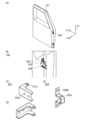
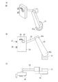
- FIG. 2A is a perspective view showing a door provided with a hinge
- FIG. 2B is an enlarged view showing a hinge portion of FIG. 2A
- FIGS. 2C and 2D are views of a hinge on the vehicle body side
- FIG. 2E is a perspective view showing the opening / closing component on the door side of the hinge.
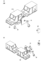
- 3 (A) and 3 (B) are perspective views showing a door mounting device according to an embodiment of the present invention.
- FIG. 4A and FIG. 4B are a plan view and a front view showing the mounting apparatus.
- FIGS. 5A to 5C are a perspective view and a plan view showing a state different from FIGS.
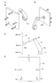
- 6 (A) to 6 (D) are a perspective view, a side view, and a front view showing a transfer robot constituting the mounting apparatus.
- FIG. 7A is a perspective view showing a state in which the transfer robot holds the door
- FIG. 7B and FIG. 7C are a side view, a front view
- FIG. 8 is an enlarged view showing a lower part of FIG.
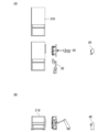
- FIGS. 8A to 8C are a perspective view, a front view, and a plan view showing the mounting robot in the mounting apparatus.
- FIG. 9A to FIG. 9C are a perspective view, a front view, and a plan view showing a fixed imaging unit constituting the attachment apparatus.
- FIG. 13A and FIG. 13B are diagrams showing a modification of the present invention.
- FIG. 1 is a side view showing a state in which a door provided with a hinge is attached to a vehicle body
- FIG. 2A is a perspective view showing a door provided with a hinge
- FIG. 2B is a view showing the hinge portion of FIG. 2 (C) and 2 (D) are perspective views showing opening / closing parts of the hinge on the vehicle body side
- FIG. 2 (E) is a perspective view showing opening / closing parts on the door side of the hinge.
- the x direction is the vehicle left-right direction
- the y direction is the vehicle front-rear direction
- the z direction is the vehicle up-down direction.
- the correspondence relationship of each axis is merely an example.
- the door 220 includes a first row door 221 and a second row door 222.
- a hinge 230 is attached to the first row door 221, and a hinge 240 is attached to the second row door 222.
- the hinge 230 rotates with the vehicle body side hinge part 231 (corresponding to the first hinge part) and the door side hinge part 232 (corresponding to the second hinge part).
- a shaft 233, a bolt 234, and a nut 235 are included.
- the vehicle body side hinge part 231 is formed in an L shape in plan view, and has mounting holes 231a through which the rotation shaft 233 is inserted and mounting holes 231b (two places) through which the bolts 234 are inserted.
- the door-side hinge part 232 is configured to have a concave shape in plan view, and has an attachment hole 232a through which the rotation shaft 233 is inserted and attachment holes 232b (two places) through which the bolts 234 are inserted.
- the hinge 230 is installed at attachment positions 230 a and 230 b on the side of the vehicle body 210.
- the mounting hole 231b at the mounting position 230a is configured as a so-called tight hole in which one of the two positions has a relatively small hole diameter with respect to the bolt diameter, and the other mounting hole 231b.
- the two attachment holes 231b at the attachment position 230b are configured as holes having a relatively large hole diameter with respect to the bolt diameter.
- the attachment positions 240a and 240b of the hinge 240 of the second row door 222 the two attachment holes 231b at the attachment positions 240a and 240b are both relatively wide with respect to the bolt hole diameter. This is the same except for the configuration.
- the attachment hole 231b is configured as a hinge attachment location.
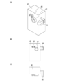
- FIGS. 5A to 5C are a perspective view and a plan view showing a state different from FIGS. 3A to 4B in the attachment apparatus.
- FIGS. 6 (A) to 6 (D) are a perspective view, a side view, and a front view showing the transfer robot constituting the attachment device, and FIGS. 7 (A) to 7 (C) hold the door in the transfer robot.
- FIG. 7D is an enlarged view showing a lower portion of FIG. 7B.
- FIGS. 8A to 8C are a perspective view, a front view, and a plan view showing an attachment robot constituting the attachment apparatus.
- FIG. 9 (A) to 9 (C) are a perspective view, a front view, and a plan view showing an imaging unit in the mounting apparatus.
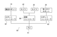
- FIG. 10 is a block diagram for explaining the configuration of the control system of the attachment apparatus, and
- FIG. 11 is an explanatory view for explaining the correction of the hinge attachment position.
- the attachment apparatus 100 includes a transfer robot 10 (corresponding to the transfer unit), an attachment robot 30 (corresponding to the attachment unit), A measurement unit 40, an AGV 50, and a control unit 60 are included.
- the transfer robot 10 includes a body part 11, arms 12, 13 and a door gripping part 14 as shown in FIGS. 6 (A) to 6 (D).
- drum 11 has the rotation part 11a in the location mounted in the ground of an apparatus.
- the trunk portion 11 is configured to be rotatable about the vertical direction with respect to the ground by the rotating portion 11a.
- the arm 12 has a rotating part 12a and is rotatably attached to the body part 11 by the rotating part 12a.
- the arm 13 has a rotating part 13a, and is attached to the arm 12 so as to be rotatable by the rotating part 13a.
- the door gripping portion 14 has a gripping mechanism 15 and gripping portions 16, 17, 18, 19, and 21.
- the gripping mechanism 15 is equipped with gears and actuators for operating the gripping portions 16 to 21, and moves the gripping portions 16 to 21 in the horizontal direction or the vertical direction to grip and release the door.
- the gripping mechanism 15 includes a rotation shaft 15a and a rotation shaft 15b.
- the rotating shaft 15a is a connecting portion with the arm 13 and rotates around the direction in which the arm 13 extends.
- the rotating shaft 15b is a connecting portion of the arm 13 with the gripping mechanism 15, and rotates the gripping mechanism 15 with a direction intersecting with the direction in which the arm 13 extends as a rotating shaft.
- the transfer robot 10 is configured as a so-called 6-axis robot.
- the gripping parts 16 and 17 are parts for gripping the lower side of the door 220.
- the gripping portions 16 and 17 are formed as abutting portions 16a and 17a in which side portions that come into contact with the outside of the door 220 are inclined and the other is substantially perpendicular. is doing.
- the gripping portions 16 and 17 are configured to be able to adjust the respective distances from the gripping mechanism 15, thereby adjusting the inclination of the door about the vertical direction of the gripped door.
- the gripping portions 16 and 17 are configured to be movable in the vertical direction with respect to the gripping mechanism 15, but may be configured to be movable in the left-right direction.
- the gripping portions 18 and 19 are installed above the gripping portions 16 and 17 in the gripping mechanism 15 and are configured to be movable in the horizontal direction.
- the gripping portions 18 and 19 sandwich the door 220 from the left-right direction (y direction in FIG. 7C) in the vicinity of the approximate center of the door 220.
- the grip portion 21 is installed above the grip portions 16 to 19 in the grip mechanism 15 and is configured to be movable in the vertical direction.
- the gripping part 21 approaches the door 220 from above, and holds the door together with the gripping parts 16 and 17 in the vertical direction (z direction in FIG. 7C).
- the transfer robot 10 holds the door 220 from two directions, that is, up, down, left, and right in FIG.
- the gripping portion 21 is formed by cutting out the sandwiching portion of the door 220 in a V shape, and the gripping portions 18 and 19 are not provided with a notch like the gripping portion 21, but are configured similarly to the gripping portion 21. May be.
- the transport robot 10 grips (holds) the door 220 from the stocked position of the door 220 with the above-described configuration, and transports the door 220 to the mounting position of the vehicle body 210 that is placed on the AGV 50 and transported.
- the attachment robot 30 includes a body part 31, arms 32 and 33, a housing 34, a camera 35, a distance measuring sensor 36, an attachment part 37, 38. Since the attachment robot 30 is configured as a six-axis robot similarly to the transfer robot 10, description of the body portion 31 and the arms 32 and 33 is omitted.
- the housing 34 is rotatably attached to the tip of the arm 33, and stores components such as a camera and a sensor for imaging the attachment position on the vehicle body side.
- the camera 35 does not acquire three-dimensional image information, but acquires and generates plane (two-dimensional) image information.
- the distance measuring sensor 36 measures the distance from the imaging position of the mounting robot 30 to the hinge mounting position on the vehicle body side when the camera 35 captures the mounting position on the vehicle body side.
- the camera 35 generates two-dimensional image information, the distance measuring sensor 36 acquires the distance of the depth to the vehicle body side, and measures the position of the hinge 230 as will be described later. Three-dimensional position information can be acquired, and a configuration like a so-called three-dimensional camera can be made unnecessary.
- the camera 35 and the distance measuring sensor 36 constitute a first measuring unit.
- the camera 35 and the distance measuring sensor 36 are configured to be arranged in parallel independently. Therefore, calibration can be facilitated, the degree of freedom in designing the installation jig can be increased, and general-purpose devices can be applied to the camera 35 and the distance measuring sensor 36, respectively, thereby suppressing an increase in cost.
- the attachment portions 37 and 38 are configured to attach bolts for fixing the door 220 to which the hinge 230 is attached to the vehicle body to the hinge attachment holes on the vehicle body side.
- the attachment portions 37 and 38 are configured such that a socket is provided at the tip so that a bolt 234 or a nut can be attached, and the socket is configured to be rotatable.
- the bolt 234 is attached, the bolt 234 is attached to the socket from the parts storage, and the bolt 234 is inserted into the hinge attachment hole 231b of the door 220 held by the transfer robot 10, and is fastened to the nut on the vehicle body side.
- 220 is attached to the vehicle body 210 so that opening and closing is possible.
- the attachment robot 30 is configured as a six-axis robot, and the attachment robot 30 is configured to include the camera 35, the distance measuring sensor 36, and the attachment portions 37 and 38.
- the camera can be moved by a 6-axis robot, and a plurality of points can be measured, and the measurement range can be widened, so that the vehicle body measuring device can be made inexpensive.
- a conveying device such as a bolt can be eliminated and the cost can be reduced, and the mounting range 37 and the degree of freedom of the angle can be expanded by mounting the mounting portions 37 and 38 on the 6-axis robot.
- measurement and bolts can be attached with a single robot, which contributes to a reduction in equipment costs.
- the measuring unit 40 includes a housing 41, a camera 42, and a distance measuring sensor 43.
- the casing 41, the camera 42, and the distance measuring sensor 43 are not provided with parts such as a gear and a motor for operating the mounting portions 37, 38, and the casing 34, the camera 35, and the distance measuring sensor. Since it is the same structure as 36, description is abbreviate
- the camera 42 and the distance measuring sensor 43 constitute a second measuring unit.
- the casing 41 is provided with a positioning portion 44.
- the positioning unit 44 is installed in the housing 41 and positions the hinge 230 attached to the door 220. Since the hinge 230 is a rotating part, the transfer robot 10 does not transfer the door 220 to the vehicle body 210 as it is while holding the door 220, but instead of the door 220 as shown in FIGS. 5 (A) to 5 (C).
- the hinge 230 is once pressed against the positioning portion 44 provided in the housing 41 so that the rotation angles of the vehicle body side hinge part 231 and the door side hinge part 232 are made to coincide with each other, and then conveyed to the vehicle body 210.
- the positioning portion 44 is made of a relatively rigid material such as iron or steel plate in order to position the hinge 230. However, other materials may be used as long as the hinge 230 can be positioned.
- a dedicated robot or an AGV facility is not prepared for each vehicle type, but a general-purpose robot is used to attach components such as a door. For this reason, when the transfer robot 10 grips the door 220, there may be a deviation from the position assumed in advance in the design stage, and the same holds true for the AGV 50 that transfers the vehicle body 210. Therefore, an operation for correcting the position to the design position (reference position) is required.
- the attachment of parts such as a door using a robot is performed in a three-dimensional manner such as a specific part of the part, that is, the position of the hinge attachment part of the door 220 in the case of the door 220.
- a correct position (x, y, z) and a rotation angle (w, p, r) in each direction of xyz at that position are measured and compared with data of a preset reference position to obtain a correction amount.
- the rotation direction is set in advance, and the hinge can be rotated in the rotation direction even after attachment.
- the hinge attachment location on the door is first attached to the hinge attachment location on the vehicle body, and the hinge is pivoted in a state where the hinge is pivotable.
- the AGV 50 is a so-called automated guided vehicle, and transports the vehicle body before the door is attached.
- the AGV 50 may be configured such that a plurality of pins are installed, and a vehicle body having different specifications such as size and shape is placed in accordance with the pins, thereby aligning the vehicle body 210 having various specifications. .
- the control unit 60 includes a PLC 61, robot controllers 62 and 63, and a visual controller 64.
- the robot controller 62 controls the operation of the transfer robot 10, and the robot controller 63 controls the operation of the mounting robot 30.
- the visual controller 64 controls the camera 35 mounted on the attachment robot 30 and the camera 42 of the imaging unit 40.
- a PLC (Programmable Logic Controller) 61 controls the robot controllers 62 and 63, the visual controller 64, and the like. Further, the PLC 61 also collects distance information from the distance measuring sensors 36 and 43 and performs control.
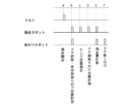
- FIG. 12 is a time chart for explaining a door mounting method according to the present embodiment.
- the vehicle body 210 is placed on the AGV 50 and conveyed to the door mounting area (point a in FIG. 12).
- the transfer robot 10 grips the door 220 from a component installation location (not shown) (point b in FIG. 12).
- the mounting robot 30 images the mounting positions 230a and 230b of the hinge 230 on the vehicle body 210 with the camera 35, and the distance measuring sensor 36 measures the distance in the depth direction of the mounting positions 230a and 230b (FIG. 12).
- Point b) the mounting position on the vehicle body side is the second mounting position
- the mounting position on the door side is the first mounting position.
- the gripping of the door and the measurement of the second mounting position in FIG. 12 are examples, and the gripping of the door 220 by the transport robot 10 and the measurement of the second mounting position by the camera 35 and the distance measuring sensor 36 are performed at the same time. You don't have to.
- the transfer robot 10 presses the gripped door 220 toward the positioning unit 44 provided in the imaging unit 40 as shown in FIGS. 5A to 5C, and the vehicle body side hinge part 231 and the door are pressed. It is set as the state rotated to the state which matched the side hinge component 232 (the state which both are in the same phase) (point c of FIG. 12).
- the camera 42 of the imaging unit 40 images two hinge mounting positions of the door-side hinge 230, and the distance measuring sensor 36 measures the first mounting position by measuring the distance in the depth direction (point of FIG. 12). d).
- the PLC 61 compares the measurement result of the mounting position on the vehicle body side obtained from the camera 35 and the distance measuring sensor 36 with a reference position such as a preset design value, and calculates a correction amount.
- a reference position such as a preset design value
- the correction amount is 0.1 mm in absolute value in the x direction.
- the correction amount for the first attachment position on the door side is the first correction amount
- the correction amount for the second attachment position on the vehicle body side is the second correction amount
- r is the same as the rotation axis of the hinge of the hinge 230. Since the rotation is possible, the calculation is unnecessary.
- the PLC 61 similarly obtains the (first) correction amount with respect to the reference position from the measurement result on the door side.
- the correction amount in this case is 0.1 mm in absolute value in the x direction.
- the PLC 61 adds the correction amount on the vehicle body side and the correction amount on the door side to obtain the correction amount for the position taught in advance of the door 220.
- the PLC 61 transmits data for conveying the door 220 to the position deviated by ⁇ 0.2 mm in the x direction with respect to the previously taught conveyance position. To the transfer robot 10 (point e in FIG. 12).
- the transfer robot 10 transfers and positions the door 220 to the transfer position received from the robot controller 63, and the attachment robot 30 performs bolt fastening by either one of the attachment portions 37 and 38.
- the bolt is fastened from the tight hole at the attachment position 230a, and then the rotation shaft 15a of the transfer mechanism 15 of the transfer robot 10 is rotated, and the remaining attachment position 230b is also bolted by either of the attachment portions 37 and 38. Fastening is performed (point f in FIG. 12).
- the door 220 is attached to the vehicle body 210 by rotating the door 220 around the rotation axis of the hinge 230 to a position where the door 220 is attached, that is, a position where the door 220 is fully closed.
- the opening / closing component mounting apparatus 100 and mounting method for an automobile sandwich the door 220 having two hinge mounting portions 230a and 230b from two directions by the transfer robot 10, and the camera 42 and The distance measuring sensor 43 measures the attachment positions 230a and 230b on the door side.
- the hinge attachment positions 230 a and 230 b on the vehicle body side are measured by the camera 35 and the distance measuring sensor 36.
- the control unit 60 calculates the correction amounts of the hinge attachment positions on the vehicle body side and the door side, determines the conveyance position of the door 220 in consideration of them, conveys the door 220 to the vehicle body 210, and attaches the attachment unit 37,
- the door 220 is attached to the vehicle body 210 by 38.
- the transfer robot 10 attaches the attachment hole 231b of the vehicle body side hinge part 231 attached to the door 220 to the hinge attachment location in the vehicle body 210 so that the door 220 can rotate around the rotation axis of the hinge 230, and the door 220 is hinged.
- the vehicle body 210 is rotated about the rotation axis 230 to a position where the vehicle body 210 is attached, that is, a position where the door 220 is closed.
- the number of measurement points can be reduced from the conventional three points to two hinge mounting positions 230a and 230b, thereby reducing the specifications required for the equipment and reducing the equipment cost.
- the measurement time can be shortened.
- the door 220 is configured to be clamped from two directions by the gripping portions 16, 17, 18, 19, and 21 of the transport robot 10, the door 220 that is sandwiched when the transport position is calculated by the control unit 60 is used. It can be conveyed to the vehicle body 210 without rattling, and the door 220 can be attached quickly and accurately.
- the transfer robot 10 includes gripping portions 16 and 17 that support the door 220 from the lower portion of the door 220, and the gripping portions 16 and 17 are abutting portions 16a that restrict rotation of the door 220 with the horizontal direction as a rotation axis. , 17a. Therefore, the variation in door mounting posture can be suppressed with a simple shape, which can contribute to the reduction in equipment costs.
- the vehicle body side hinge part 231 and the door side hinge part 232 constituting the hinge 230 are rotated by the positioning unit 44 provided in the imaging unit 40. In this state, the image is taken in a state matched with the above. Since the hinge may rotate and its position in the rotational direction may change, the position of the door 220 can be quickly determined by attaching the posture of the hinge 230 by the positioning unit 44 and can be attached to the vehicle body 210 with high accuracy.
- the positioning by the positioning unit 44 may be configured such that the position in the rotational direction is determined so that the vehicle body side hinge part 231 and the door side hinge part 232 are fully opened in the rotational direction.
- the camera 35 and the distance sensor 36 in the attachment robot 30 and the camera 42 and the distance sensor 43 in the imaging unit 40 are configured to be arranged in parallel independently. Therefore, calibration becomes easy and the degree of freedom in designing the installation jig can be increased. Moreover, since general-purpose equipment can be applied to the camera and the distance measuring sensor, the equipment cost can be reduced.
- the correction amount of the door which is a workpiece
- the output of the cameras 35 and 42 is treated as the plane direction
- the output of the distance measuring sensors 36 and 43 is treated as the depth direction, thereby calculating the correction amount with a simple vector. It can be performed by calculation, and a general PLC used for FA (Factory Automation) control can be used as a computing device, and cost can be reduced.
- FA Vectory Automation
- the mounting robot 30 is configured to be equipped with a camera 35 for measuring, a distance measuring sensor 36, and mounting portions 37 and 38 for mounting bolts 234 and nuts 235. Therefore, measurement at a plurality of points is possible and the measurement range can be widened, so that the vehicle body measurement device can be made inexpensive. In addition, it is not necessary to prepare a separate device for carrying bolts and nuts, and the cost can be reduced accordingly. Further, the mounting range 37 and the degree of freedom can be expanded by mounting the mounting portions 37 and 38 on a 6-axis robot. Furthermore, measurement and fastening can be performed with one robot, and the equipment cost can be reduced.
- the vehicle body side hinge part 231 and the door side hinge part 232 constituting the hinge 230 are attached to the door 220.
- the present invention is not limited to this.
- the vehicle body side hinge component 231 may be attached to the vehicle body 210, and the door side hinge component 232 may be attached to the door 220.
- the hinge mounting locations are the mounting holes 231a and 232a.
- the vehicle body side hinge part 231 and the door side hinge part 232 may be configured to be attached to the vehicle body 210 together with the rotating shaft 233.
- the hinge mounting location is the mounting hole 232b.
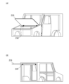
- FIG. 13 (A) and FIG. 13 (B) are diagrams showing a modification of the present invention.
- the present invention is not limited to this, and the back door 224 attached to the bonnet 223 or the rear portion of the vehicle body may be used.
- the positioning part 44 demonstrated embodiment provided in the housing
- Transfer robot (transfer unit), 16, 17 Grasping part (support part), 16a, 17a Butting part (regulation part), 100 Automotive component mounting apparatus, 210 body, 220 (side) door (opening and closing parts), 223 Bonnet, 224 backdoor, 230 hinge, 230a, 230b hinge mounting position, 231 body side hinge part (first hinge part), 232 Door side hinge part (second hinge part), 30 Mounting robot (mounting part), 35 camera (first measurement unit), 36 Distance sensor (first measurement unit), 40 Measuring unit, 42 camera (second measuring unit), 43 Distance sensor (second measurement unit), 44 Positioning part, c Reference position.
Landscapes
- Engineering & Computer Science (AREA)
- Manufacturing & Machinery (AREA)
- Chemical & Material Sciences (AREA)
- Combustion & Propulsion (AREA)
- Transportation (AREA)
- Mechanical Engineering (AREA)
- Automobile Manufacture Line, Endless Track Vehicle, Trailer (AREA)
- Automatic Assembly (AREA)
Abstract
【課題】汎用の設備を用いつつ設備のコストを安くすることができる自動車の開閉部品の取り付け装置及び取り付け方法を提供する。 【解決手段】本発明に係る自動車のドアの取付け装置100は、ドア220を少なくとも2方向から挟持する搬送ロボット10と、取り付けロボット30と、カメラ35、42および測距センサー36、43と、カメラ42と測距センサー36が計測した車体210のヒンジ第1取り付け位置の基準位置に対する第1補正量とカメラ35と測距センサー43とが計測したドアのヒンジ第2取り付け位置の基準位置に対する第2補正量とからドアの車体に対する搬送位置を決定する制御部60と、を有し、搬送ロボット10はドアにおけるヒンジ取り付け箇所を車体におけるヒンジ取り付け箇所に取り付けてドアをヒンジの回転軸周りに回動可能とし、ドアをヒンジの回転軸周りにドアの取り付け位置まで回動させる。
Description
本発明はドアなどの自動車の開閉部品を車体に取り付ける取り付け装置及び取り付け方法に関する。
自動車は何万点にもおよぶ部品をボルト締結、接着、または溶接などによって接合し、組み立てることで製造される。例えば、車室への出入り口にあたるドアの取り付けは、車体を生産ラインに搬送し、ドアの取り付け位置に来た状態でロボットがドアを車体まで搬送し、別のロボットがボルト締結を行う(特許文献1参照)。
上記のように自動車は何万点にも及ぶ部品を取り付けて完成する製品であるため、部品同士の取り付け精度は重要な項目となる。しかし、取り付け精度を高くしようとして1つの車種毎に専用の取り付け治具を用意したり、取り付け位置を確認するためのセンサーやカメラを何台も用意したりするのでは、設備の償却費用で製品の原価が高くなってしまい、競合他社との間の価格競争力において優位性を発揮できない、といった問題がある。
そこで本発明は上記課題を解決するためになされたものであり、汎用の設備を用いつつ設備のコストを安くすることができる自動車の開閉部品の取り付け装置及び取り付け方法を提供することを目的とする。
上記目的を達成する本発明は、車体に対してヒンジによって取り付けられる自動車の開閉部品を取り付ける取り付け装置である。当該装置は2箇所のヒンジ取り付け箇所を備えた開閉部品を少なくとも2方向から挟持して車体に搬送する搬送部と、開閉部品を車体に取り付ける取り付け部と、開閉部品側における2箇所のヒンジ取り付け箇所を第1取り付け位置として計測する第1計測部と、車体における2箇所のヒンジ取り付け箇所を第2取り付け位置として計測する第2計測部と、第1計測部が計測した第1取り付け位置の予め設定した基準位置に対する第1補正量と第2計測部が計測した第2取り付け位置の基準位置に対する第2補正量とをそれぞれ計算し、第1補正量および第2補正量とを考慮して開閉部品の車体に対する搬送位置を決定する制御部と、を有する。搬送部は、開閉部品におけるヒンジ取り付け箇所を車体におけるヒンジ取り付け箇所に取り付けて開閉部品をヒンジの回転軸まわりに回動可能とし、開閉部品をヒンジの回転軸周りに車体の取り付け位置まで回動させることを特徴とする。
また、他の本発明は車体に対してヒンジによって取り付けられる自動車の開閉部品を取り付ける取り付け方法である。当該方法は2箇所のヒンジ取付け箇所を備えた開閉部品を少なくとも2方向から挟持し、開閉部品側における2箇所のヒンジ取り付け箇所を第1取付け位置として計測し、車体側における2箇所のヒンジ取り付け箇所を第2取付け位置として計測し、開閉部品側において計測した第1取り付け位置の予め設定した基準位置に対する第1補正量と車体側において計測した第2取り付け位置の基準位置に対する第2補正量とを考慮して開閉部品の車体に対する搬送位置を決定し、開閉部品におけるヒンジ取り付け箇所を車体におけるヒンジ取り付け箇所に取り付けて開閉部品をヒンジの回転軸周りに回動可能とし、開閉部品をヒンジの回転軸まわりに車体の取り付け位置まで回動させることを特徴とする。
以下、添付した図面を参照しながら、本発明の実施形態を説明する。なお、以下の記載は特許請求の範囲に記載される技術的範囲や用語の意義を限定するものではない。また、図面の寸法比率は説明の都合上誇張されており、実際の比率とは異なる場合がある。
図1は車体にヒンジを備えたドアを取り付けた状態を示す側面図、図2(A)はヒンジを備えたドアを示す斜視図、図2(B)は図2(A)のヒンジ部分を示す拡大図、図2(C)、(D)は車体側のヒンジの開閉部品を示す斜視図、図2(E)はヒンジのドア側の開閉部品を示す斜視図である。なお、図2(A)、図7(A)に示す座標系はx方向が車両左右方向、y方向が車両前後方向、z方向が車両上下方向であり、z方向は後述するヒンジ230の回転軸と一致するが、各軸の対応関係はあくまで例示である。
(ヒンジ機構)
まず本実施形態により取り付けられる部品について説明する。本実施形態では自動車の車体210にサイドドア220を取り付ける場合について説明するが一例であり、これに限定されない。ドア220は、図1に示すように一列目ドア221と二列目ドア222とを有する。一列目ドア221にはヒンジ230が取り付けられ、二列目ドア222にはヒンジ240が取り付けられる。ヒンジ230は図2(B)~図2(E)に示すように車体側ヒンジ部品231と(第1ヒンジ部品に相当)、ドア側ヒンジ部品232(第2ヒンジ部品に相当)と、回動軸233と、ボルト234と、ナット235と、を有する。
まず本実施形態により取り付けられる部品について説明する。本実施形態では自動車の車体210にサイドドア220を取り付ける場合について説明するが一例であり、これに限定されない。ドア220は、図1に示すように一列目ドア221と二列目ドア222とを有する。一列目ドア221にはヒンジ230が取り付けられ、二列目ドア222にはヒンジ240が取り付けられる。ヒンジ230は図2(B)~図2(E)に示すように車体側ヒンジ部品231と(第1ヒンジ部品に相当)、ドア側ヒンジ部品232(第2ヒンジ部品に相当)と、回動軸233と、ボルト234と、ナット235と、を有する。
車体側ヒンジ部品231は、平面視L字状に形成され、回動軸233を挿通する取り付け穴231aとボルト234を挿通する取り付け穴231b(2箇所)を有する。ドア側ヒンジ部品232は平面視凹形状に構成され、回動軸233を挿通する取り付け穴232aとボルト234を挿通する取り付け穴232b(2箇所)とを有する。ヒンジ230は、車体210の側部における取り付け位置230a、230bに設置される。また、本実施形態において取り付け位置230aの取り付け穴231bは2箇所のうち一箇所は穴径がボルト径に対して比較的余裕の少ない、いわゆるタイトな穴として構成し、もう一箇所の取り付け穴231bと取り付け位置230bの2箇所の取り付け穴231bはボルト径に対して穴径に比較的ゆとりのある穴として構成している。二列目ドア222のヒンジ240の取り付け位置240a、240bはヒンジ230の構成に対して取り付け位置240a、240bにおける2箇所の取り付け穴231bをいずれもボルト穴径に対して比較的ゆとりのある穴として構成している点以外は同様である。なお、本実施形態において取り付け穴231bはヒンジ取り付け箇所として構成している。
(自動車の開閉部品の取り付け装置)
次にドアを例に挙げて自動車の開閉部品の取り付け装置について説明する。図3(A)、図3(B)、図4(A)、図4(B)は本発明の一実施形態に係るドアの取り付け装置を示す斜視図、平面図、正面図である。図5(A)~図5(C)は同取り付け装置において図3(A)~図4(B)とは異なる状態を示す斜視図、平面図である。
次にドアを例に挙げて自動車の開閉部品の取り付け装置について説明する。図3(A)、図3(B)、図4(A)、図4(B)は本発明の一実施形態に係るドアの取り付け装置を示す斜視図、平面図、正面図である。図5(A)~図5(C)は同取り付け装置において図3(A)~図4(B)とは異なる状態を示す斜視図、平面図である。
図6(A)~図6(D)は同取り付け装置を構成する搬送ロボットを示す斜視図、側面図、正面図、図7(A)~図7(C)は同搬送ロボットにおいてドアを把持させた状態を示す斜視図、側面図、正面図、図7(D)は図7(B)の下部を示す拡大図である。図8(A)~図8(C)は同取り付け装置を構成する取り付けロボットを示す斜視図、正面図、平面図である。
図9(A)~図9(C)は同取り付け装置において撮像部を示す斜視図、正面図、平面図である。図10は同取り付け装置の制御系の構成について説明するブロック図、図11はヒンジの取り付け位置の補正について説明する説明図である。
図3(A)、図3(B)、図10を参照して本実施形態に係る取付け装置100は、搬送ロボット10(搬送部に相当)と、取り付けロボット30(取付け部に相当)と、計測部40と、AGV50と、制御部60と、を有する。
搬送ロボット10は、図6(A)~図6(D)に示すように胴体部11と、アーム12、13と、ドア把持部14と、を有する。胴体部11は、装置の地面に載置される箇所で回転部11aを有する。胴体部11は、回転部11aによって地面に対して鉛直方向を回転軸として回転できるように構成している。アーム12は回転部12aを有し、回転部12aによって胴体部11に回転可能に取り付けられている。アーム13は、回転部13aを有し、回転部13aによってアーム12に対して回転可能に取り付けている。
ドア把持部14は、把持機構15と、把持部16、17、18、19、21と、を有する。把持機構15は、把持部16~21を動作させるためのギアやアクチュエーターなどを搭載しており、把持部16~21を水平方向または鉛直方向に移動させ、ドアの把持および把持の解除を行う。また、把持機構15は、回転軸15aと回転軸15bと、を有する。
回転軸15aはアーム13との接続部であって、アーム13の伸びる方向を軸として回転させる。回転軸15bは、アーム13の把持機構15との接続部であって、アーム13が伸びる方向と交差する方向を回転軸として把持機構15を回転させる。搬送ロボット10はいわゆる6軸ロボットとして構成している。
把持部16、17(支持部に相当)は、ドア220の下方を把持する部位である。把持部16、17は、図7(D)に示すようにドア220の外方と接触する側方の部位が傾斜して形成され、他方が略直角になった突き当て部16a、17aとして構成している。これにより図7(A)に示すようにドア220を支持した際に水平方向を軸とした回転を抑制してドア220を搬送できるように構成している。また、把持部16,17は把持機構15からのそれぞれの距離を調節可能に構成しており、これによって把持したドアの鉛直方向を軸とするドアの傾きを調整することができる。また、把持部16、17は、把持機構15に対して上下方向に移動可能に構成しているが、左右方向に移動可能に構成してもよい。
把持部18、19は、図7(C)に示すように把持機構15において把持部16、17よりも上部に設置し、水平方向に移動可能に構成されている。把持部18、19は、ドア220の略中央付近における左右方向(図7(C)のy方向)からドア220を挟持する。把持部21は、図7(B)に示すように把持機構15において把持部16~19よりも上部に設置し、上下方向に移動可能に構成している。把持部21は、上方からドア220に接近し、把持部16、17と共にドアを上下方向(図7(C)のz方向)に挟持する。このように搬送ロボット10は、ドア220を図7(C)の上下左右方向の2方向から挟持する。また、把持部21は、ドア220の挟持部分をV字状に切り欠いて形成し、把持部18、19は把持部21のような切り欠きを設けていないが、把持部21と同様に構成してもよい。
搬送ロボット10は、上記のような構成によってドア220のストックされている位置からドア220を把持(挟持)し、AGV50に載置されて搬送された車体210の取り付け位置にドア220を搬送する。
取り付けロボット30は、図8(A)~図8(C)に示すように胴体部31と、アーム32、33と、筐体34と、カメラ35と、測距センサー36と、取付け部37、38と、を有する。取付けロボット30は、搬送ロボット10と同様に6軸ロボットとして構成しているため、胴体部31、アーム32、33の説明を省略する。筐体34は、アーム33の先端に回転可能に取り付けられ、車体側の取り付け位置を撮像するカメラやセンサーなどの部品を格納している。
カメラ35は、3次元的な画像情報を取得するものではなく、平面(二次元)の画像情報を取得、生成する。測距センサー36は、カメラ35による車体側の取り付け位置を撮像する際に取り付けロボット30の撮像位置から車体側のヒンジ取り付け位置までの距離を測定する。カメラ35が2次元的な画像情報を生成し、測距センサー36が車体側までの奥行きの距離を取得して、後述のようなヒンジ230の位置を計測することによって、ドア220の搬送位置の3次元的な位置情報を取得することができ、いわゆる3次元カメラのような構成を不要にすることができる。カメラ35と測距センサー36は第1計測部を構成する。
また、カメラ35と測距センサー36とは独立して並列に並べるように構成している。そのため、キャリブレーションを容易にでき、設置治具設計の自由度を大きくすることができ、カメラ35および測距センサー36にそれぞれ汎用機器を適用できてコストアップを抑制することができる。
取付け部37、38はヒンジ230を取り付けたドア220を車体に固定するためのボルトを取り付けて車体側のヒンジ取り付け穴に取り付ける構成である。取付け部37、38は先端にソケットを設けてボルト234やナットを取り付けることができるように構成しており、当該ソケットは回転可能に構成している。ボルト234を取り付ける際には部品置き場からボルト234をソケットに取り付け、搬送ロボット10によって保持されているドア220のヒンジの取り付け穴231bにボルト234を挿通させ、車体側のナットと締結することによってドア220が車体210に開閉可能に取り付けられる。
このように、取り付けロボット30は6軸ロボットとして構成し、取り付けロボット30にカメラ35と測距センサー36と取付け部37、38とを備えるように構成している。そのため、6軸ロボットによってカメラなどを動かせることができて複数点の計測が可能となり、計測範囲も広くできるため、車体の計測装置を安価にすることができる。また、ボルトなどの搬送装置を不要にできて安価にすることができ、6軸ロボットに取付け部37,38を搭載することによって取り付け範囲や角度の自由度を拡大させることができる。また、一台のロボットで計測やボルトなどの取り付けが可能となり、設備コストの低減に寄与することができる。
計測部40は、筐体41と、カメラ42と、測距センサー43と、を有する。筐体41、カメラ42、および測距センサー43は、取付け部37、38を動作させるためのギアやモーターなどの部品を搭載していない点を除いて筐体34、カメラ35、および測距センサー36と同様の構成であるため説明を省略する。なお、カメラ42と測距センサー43は第2計測部を構成する。
また、筐体41には位置決め部44が設けてある。位置決め部44は、筐体41に設置し、ドア220に取り付けられたヒンジ230の位置決めを行なう。ヒンジ230は回転する部品であるため、搬送ロボット10は、ドア220を把持した状態でそのまま車体210に搬送するのではなく、図5(A)~図5(C)に示すようにドア220のヒンジ230を筐体41に設けられた位置決め部44に一度押し当てて、車体側ヒンジ部品231とドア側ヒンジ部品232の回転角を一致させた状態にし、そのうえで車体210へ搬送する。このように構成することによって、回転可能なヒンジであっても所定の回転位置にセットした状態で車体210に搬送することができ、車体210への取り付けをスムーズかつ精度よく行うことができる。位置決め部44はヒンジ230の位置決めを行なうために比較的剛性のある鉄や鋼板などの材料によって構成しているが、ヒンジ230の位置決めが実施できれば、その他の材料であってもよい。
ここでドア220の取り付け位置の補正について説明する。本実施形態では自動車の一車種毎に専用のロボットやAGVのような設備を用意するのではなく、汎用のロボットを使用してドアなどの構成部品の取り付けを行うように構成している。そのため、搬送ロボット10がドア220を把持した際には設計段階などで予め想定した位置とずれを生じている場合があり、車体210を搬送するAGV50についても同様であるため、ドアは挟持した状態から設計上の位置(基準位置)に補正する動作が必要になる。
ロボットを用いたドアなどの部品の取り付けは、図7(A)~図7(C)に示すように部品の特定箇所、ドア220で言えばドア220のヒンジ取り付け箇所の位置などの3次元的な位置(x、y、z)とその位置でのxyzの各方向における回転角度(w、p、r)を測定し、予め設定した基準位置のデータと比較して補正量を求める。
ドアのような3次元の物体の位置補正の場合、通常であれば3点以上の特徴的な位置の測定が必要となる。しかし、ヒンジの場合、回転方向は予め設定されており取付け後もヒンジの回転方向への回転は可能である。そのため、本実施形態ではドアにおけるヒンジの取り付け箇所を先に車体のヒンジ取り付け箇所に取り付けて、ヒンジを回動可能とした状態でヒンジを回動させてドアを取り付ける。このように構成することによって、6軸のうちの1つの自由度を特定する必要をなくし、測定箇所を2箇所にすることができ、取り付け装置の計測系の部品構成を簡略化してコスト低減を図ることができる。また、車体210およびドア220の保持状態から各々の基準位置に対する補正量を求めて当該位置に補正を行うことによって、汎用の設備を用いても精度よく部品の取り付けを行うことができ、車種毎に別の設備を設置する必要がない分、設備のコストを下げることができる。
AGV50は、いわゆる無人搬送(台)車(Automated Guided Vehicle)であり、ドアが取り付けられる前の車体を載置させて搬送する。なお、AGV50には複数のピンを設置し、当該ピンに合わせて大きさや形状といった異なる仕様の車体を載置することによって、様々な仕様の車体210の位置合わせを行なうように構成してもよい。
次に取り付け装置100の制御系の構成について説明する。制御部60は、PLC61と、ロボットコントローラ62、63と、視覚コントローラ64と、を有する。ロボットコントローラ62は搬送ロボット10の動作を制御し、ロボットコントローラ63は取り付けロボット30の動作を制御する。視覚コントローラ64は、取付けロボット30に搭載されたカメラ35や撮像部40のカメラ42を制御する。PLC(Programmable Logic Controller)61は、ロボットコントローラ62、63や視覚コントローラ64などを制御する。また、PLC61には測距センサー36、43からの距離情報なども収集し、制御を行う。
(自動車の開閉部品の取付け方法)
次にドアを例に本実施形態にかかる自動車の開閉部品の取り付け方法について説明する。図12は本実施形態にかかるドアの取り付け方法を説明するタイムチャートである。
次にドアを例に本実施形態にかかる自動車の開閉部品の取り付け方法について説明する。図12は本実施形態にかかるドアの取り付け方法を説明するタイムチャートである。
まず、AGV50に車体210が載置されてドアの取り付けエリアへと搬送される(図12のポイントa)。次に搬送ロボット10は、不図示の部品設置場所からドア220を把持する(図12のポイントb)。それと同じ時間帯に取り付けロボット30は、カメラ35によってヒンジ230の車体210における取り付け位置230a、230bを撮像し、測距センサー36は取付け位置230a、230bの奥行き方向の距離を測定する(図12のポイントb)。本実施形態において車体側の取付け位置は第2取付け位置、ドア側の取り付け位置は第1取付け位置とする。また、図12におけるドアの把持と第2取付け位置計測は例示であって、厳密に搬送ロボット10によるドア220の把持とカメラ35および測距センサー36による第2取り付け位置の計測は同時刻に行なわれなくてもよい。
次に搬送ロボット10は、図5(A)~図5(C)に示すように把持したドア220を撮像部40に設けられた位置決め部44に向って押付けて、車体側ヒンジ部品231とドア側ヒンジ部品232とを一致させた状態(両者が同じ位相にある状態)まで回転した状態とする(図12のポイントc)。そして、撮像部40のカメラ42はドア側のヒンジ230のヒンジ取付け位置2箇所を撮像し、測距センサー36は奥行き方向の距離を測定して第1取付け位置の計測を行なう(図12のポイントd)。
次にPLC61は、カメラ35および測距センサー36から得られた車体側の取付け位置の計測結果から予め設定した設計値などの基準位置との比較を行い、補正量を算出する。例えば、図11に示すように取り付け穴231bの穴位置が基準位置Cから図11で見てx方向に+0.1mmずれていたとする。その場合、補正量はx方向に絶対値で0.1mmとなる。上記は説明の便宜のため簡略化しているが、実際はこれが上記のx、y、z、w、pについて算出される。なお、ドア側の第1取り付け位置に対する補正量は第1補正量、車体側の第2取り付け位置に対する補正量は第2補正量とし、rはヒンジ230のヒンジの回転軸と同じであり、ヒンジが回転可能であることによって算出不要としている。
PLC61は同様にドア側の計測結果からも基準位置との(第1)補正量を求める。例えば、本実施形態ではドア側のボルト取り付け穴が基準位置に対してx方向に-0.1mmずれていたとする。この場合の補正量はx方向に絶対値で0.1mmとなる。
次にPLC61は、車体側の補正量とドア側の補正量とを合算してドア220の予め教示している位置に対する補正量を求める。上記では車体側、ドア側のいずれも0.1mmずつずれているため、PLC61は予め教示した搬送位置に対してx方向に-0.2mmずれた位置にドア220を搬送するデータをロボットコントローラ63を通じて搬送ロボット10に送信する(図12のポイントe)。
そして、搬送ロボット10はロボットコントローラ63から受信した搬送位置にドア220を搬送して位置決めし、取り付けロボット30は取付け部37、38のいずれかによってボルト締結を行う。本実施形態では、取り付け位置230aのタイト穴からボルト締結を行い、その後搬送ロボット10の搬送機構15の回転軸15aを回転させて残りの取り付け位置230bについても取り付け部37、38のいずれかによってボルト締結を行う(図12のポイントf)。そして、ドア220をヒンジ230の回転軸周りにドア220を取り付ける位置、すなわちドア220を閉めきる位置まで回動させて、ドア220を車体210に取り付ける。
(作用効果)
次に本実施形態にかかる作用効果について説明する。自動車は何万点にも及ぶ部品を取り付けて完成する製品であるため、部品同士の取り付け精度は重要な項目とされている。しかし、取り付け精度を高くしようとして1つの車種毎に専用の取り付け治具を用意したり、取り付け位置を確認するために高額なセンサーやカメラを用意したりするのでは設備の償却費用で製品の原価を圧迫してしまい、競合他社との間の価格競争力において優位性を発揮することができない。
次に本実施形態にかかる作用効果について説明する。自動車は何万点にも及ぶ部品を取り付けて完成する製品であるため、部品同士の取り付け精度は重要な項目とされている。しかし、取り付け精度を高くしようとして1つの車種毎に専用の取り付け治具を用意したり、取り付け位置を確認するために高額なセンサーやカメラを用意したりするのでは設備の償却費用で製品の原価を圧迫してしまい、競合他社との間の価格競争力において優位性を発揮することができない。
これに対し、本実施形態にかかる自動車の開閉部品の取り付け装置100および取り付け方法は、2箇所のヒンジ取り付け箇所230a、230bを備えたドア220を搬送ロボット10によって2方向から挟持し、カメラ42および測距センサー43によってドア側の取り付け位置230a、230bを計測する。車体側のヒンジ取り付け位置230a、230bはカメラ35および測距センサー36によって計測する。そして、制御部60によって車体側およびドア側それぞれのヒンジ取り付け位置の補正量を算出し、それらを考慮してドア220の搬送位置を決定し、ドア220を車体210に搬送して取付け部37、38によってドア220を車体210に取り付けている。このように、搬送ロボット10によるドア220の位置決めは補正を前提として行っているため、専用の設備を用意しなくても汎用の設備で対応することができ、コスト低減に寄与することができる。
また、搬送ロボット10は、ドア220に取り付けられた車体側ヒンジ部品231の取り付け穴231bを車体210におけるヒンジ取り付け箇所に取り付けてドア220をヒンジ230の回転軸まわりに回転可能とし、ドア220をヒンジ230の回転軸周りに車体210の取り付け位置、すなわちドア220を閉める位置まで回動させるように構成している。このように構成することによって、計測箇所を従来の3ヵ所からヒンジの取り付け位置230a、230bの2箇所に減らすことができ、その分設備に要求される仕様を減らして設備コストの低減を図ることができ、さらに測定時間の短縮を図ることもできる。また、ドア220は搬送ロボット10の把持部16、17、18、19、21によって2方向から挟持するように構成しているため、制御部60によって搬送位置を算出した際に挟持したドア220をガタつかせることなく車体210まで搬送でき、ドア220の取り付けを迅速かつ精度よく行うことができる。
また、搬送ロボット10は、ドア220の下部からドア220を支持する把持部16、17を有し、把持部16、17はドア220の水平方向を回転軸とした回転を規制する突き当て部16a、17aを有するように構成している。そのため、簡易的な形状でドアの取り付け姿勢のバラつきを抑制し、設備コストの抑制に寄与することができる。
また、ドア220においてヒンジ230の取り付け位置230a、230bを撮像する前にはヒンジ230を構成する車体側ヒンジ部品231とドア側ヒンジ部品232とを撮像部40に設けられた位置決め部44によって回転方向に一致させた状態にして撮像を行っている。ヒンジは回転して回転方向における位置が変化する可能性があるため、位置決め部44によってヒンジ230の姿勢を決めることによってドア220の位置を迅速に位置決めし、精度よく車体210に取り付けることができる。なお、位置決め部44による位置決めは、車体側ヒンジ部品231とドア側ヒンジ部品232とを回転方向に開ききった状態にするようにして回転方向の位置を決めるように構成してもよい。
また、取り付けロボット30におけるカメラ35や測距センサー36および撮像部40におけるカメラ42や測距センサー43は独立して並列に並べるように構成している。そのため、キャリブレーションが容易になり、設置治具設計の自由度を大きくすることができる。また、カメラや測距センサーに汎用機器を適用できるため、設備コストを抑制することができる。
また、ワークであるドアの補正量を微小角にした場合、カメラ35、42による出力を平面方向、測距センサー36、43による出力を奥行き方向として扱うことによって、補正量の計算を簡便なベクトル演算によって行うことができ、FA(Factory Automation)制御用に用いられる一般的なPLCを計算装置として利用することができ、コスト抑制を図ることができる。
また、取り付けロボット30には計測を行うカメラ35、測距センサ-36およびボルト234やナット235を取り付ける取付け部37、38を搭載するように構成している。そのため、複数点の計測が可能、および計測範囲を広くすることができるため、車体の計測装置を安価にすることができる。また、ボルトやナットを運ぶ装置を別途用意する必要がなくなり、その分コスト低減を図ることができる。また、取付け部37、38を6軸のロボットに搭載することによって、締結可能範囲や自由度を拡大することができる。さらに、一台のロボットで計測や締結が可能となり、設備コストの抑制を図ることができる。
なお、本実施形態は上述した実施形態にのみ限定されず、特許請求の範囲において種々の変更が可能である。上記ではヒンジ230を構成する車体側ヒンジ部品231とドア側ヒンジ部品232とがドア220に取り付けられている実施形態について説明したが、これに限定されない。上記以外にも車体側ヒンジ部品231が車体210に取り付けられ、ドア側ヒンジ部品232がドア220に取り付けられるように構成することもできる。この場合、ヒンジ取り付け箇所は取り付け穴231a、232aとなる。また、車体側ヒンジ部品231およびドア側ヒンジ部品232とが回転軸233と共に車体210に取り付けられるように構成することもできる。この場合、ヒンジ取り付け箇所は取り付け穴232bとなる。
図13(A)、図13(B)は本発明の変形例を示す図である。上記では車体210に取り付ける構成部品がドア220である実施形態について説明したが、これに限定されず、ボンネット223や車体の後部に取付けられるバックドア224であってもよい。また、位置決め部44は筐体41に設ける実施形態について説明したが、筐体41とは別に構成してもよい。
10 搬送ロボット(搬送部)、
16、17 把持部(支持部)、
16a、17a 突き当て部(規制部)、
100 自動車の構成部品の取り付け装置、
210 車体、
220 (サイド)ドア(開閉部品)、
223 ボンネット、
224 バックドア、
230 ヒンジ、
230a、230b ヒンジ取り付け位置、
231 車体側ヒンジ部品(第1ヒンジ部品)、
232 ドア側ヒンジ部品(第2ヒンジ部品)、
30 取り付けロボット(取付け部)、
35 カメラ(第1計測部)、
36 測距センサー(第1計測部)、
40 計測部、
42 カメラ(第2計測部)、
43 測距センサー(第2計測部)、
44 位置決め部、
c 基準位置。
16、17 把持部(支持部)、
16a、17a 突き当て部(規制部)、
100 自動車の構成部品の取り付け装置、
210 車体、
220 (サイド)ドア(開閉部品)、
223 ボンネット、
224 バックドア、
230 ヒンジ、
230a、230b ヒンジ取り付け位置、
231 車体側ヒンジ部品(第1ヒンジ部品)、
232 ドア側ヒンジ部品(第2ヒンジ部品)、
30 取り付けロボット(取付け部)、
35 カメラ(第1計測部)、
36 測距センサー(第1計測部)、
40 計測部、
42 カメラ(第2計測部)、
43 測距センサー(第2計測部)、
44 位置決め部、
c 基準位置。
Claims (9)
- 車体に対してヒンジによって取り付けられる自動車の開閉部品を取り付ける取り付け装置であって、
2箇所のヒンジ取り付け箇所を備えた前記開閉部品を少なくとも2方向から挟持して前記車体に搬送する搬送部と、
前記開閉部品を前記車体に取り付ける取り付け部と、
前記開閉部品側における前記2箇所のヒンジ取り付け箇所を第1取り付け位置として計測する第1計測部と、
前記車体における前記2箇所のヒンジ取り付け箇所を第2取り付け位置として計測する第2計測部と、
前記第1計測部が計測した前記第1取り付け位置の予め設定した基準位置に対する第1補正量と前記第2計測部が計測した前記第2取り付け位置の前記基準位置に対する第2補正量とをそれぞれ計算し、前記第1補正量および前記第2補正量とを考慮して前記開閉部品の前記車体に対する搬送位置を決定する制御部と、を有し、
前記搬送部は、前記開閉部品における前記ヒンジ取り付け箇所を前記車体における前記ヒンジ取り付け箇所に取り付けて前記開閉部品を前記ヒンジの回転軸周りに回動可能とし、
前記開閉部品を前記ヒンジの回転軸周りに前記車体の取り付け位置まで回動させることを特徴とする自動車の開閉部品の取り付け装置。 - 前記搬送部は、前記開閉部品を下部から支持する支持部を有し、
前記支持部は水平方向を回転軸として前記開閉部品が回転することを規制する規制部を有する請求項1に記載の自動車の開閉部品の取り付け装置。 - 前記ヒンジを構成する前記車体側の第1ヒンジ部品と前記開閉部品側の第2ヒンジ部品とが前記開閉部品に取り付けられている場合において、
前記ヒンジの回転方向の位置を位置決めする位置決め部をさらに有する請求項1または2に記載の自動車の開閉部品の取り付け装置。 - 前記ヒンジは前記車体側の第1ヒンジ部品と前記開閉部品側の第2ヒンジ部品とを有し、
前記第1ヒンジ部品と前記第2ヒンジ部品とが前記開閉部品に取り付けられている状態、
前記第1ヒンジ部品が前記車体に取り付けられ前記第2ヒンジ部品が前記開閉部品に取り付けられる状態、
または前記第1ヒンジ部品と前記第2ヒンジ部品とが前記車体に取り付けられた状態のいずれかの状態において、前記取り付け部によって前記開閉部品を前記車体に取り付ける請求項1または2に記載の自動車の開閉部品の取り付け装置。 - 前記開閉部品は、自動車のサイドドア、ボンネット、又はバックドアである請求項1~4のいずれか1項に記載の自動車の開閉部品の取り付け装置。
- 車体に対してヒンジによって取り付けられる自動車の開閉部品を取り付ける取り付け方法であって、
2箇所のヒンジ取り付け箇所を備えた前記開閉部品を少なくとも2方向から挟持し、
前記開閉部品側における前記2箇所のヒンジ取り付け箇所を第1取り付け位置として計測し、
前記車体側における前記2箇所のヒンジの取り付け箇所を第2取り付け位置として計測し、
前記開閉部品側において計測した前記第1取り付け位置の予め設定した基準位置に対する第1補正量と前記車体側において計測した前記第2取り付け位置の前記基準位置に対する第2補正量とを考慮して前記開閉部品の前記車体に対する搬送位置を決定し、
前記開閉部品における前記ヒンジ取り付け箇所を前記車体における前記ヒンジ取り付け箇所に取り付けて前記開閉部品を前記ヒンジの回転軸周りに回動可能とし、
前記開閉部品を前記ヒンジの回転軸まわりに前記車体の取り付け位置まで回動させることを特徴とする自動車の開閉部品の取り付け方法。 - 前記ヒンジを構成する前記車体側の第1ヒンジ部品と前記開閉部品側の第2ヒンジ部品とが前記開閉部品に取り付けられている場合であって前記開閉部品における前記ヒンジの取り付け位置を撮像する前に、前記第1ヒンジ部品と前記第2ヒンジ部品とを開ききった状態または前記第2ヒンジ部品を回転方向において前記第1ヒンジ部品に一致させた状態に調整する請求項6に記載の自動車の開閉部品の取り付け方法。
- 前記ヒンジは前記車体側の第1ヒンジ部品と前記開閉部品側の第2ヒンジ部品とを有し、
前記第1ヒンジ部品と前記第2ヒンジ部品とが前記開閉部品に取り付けられている状態、
前記第1ヒンジ部品が前記車体に取り付けられ前記第2ヒンジ部品が前記開閉部品に取り付けられる状態、
または前記第1ヒンジ部品と前記第2ヒンジ部品とが前記車体に取り付けられた状態のいずれかの状態において前記開閉部品を前記車体に取り付ける請求項6に記載の自動車の開閉部品の取り付け方法。 - 前記開閉部品は、車両のサイドドア、ボンネット、又はバックドアである請求6から8のいずれか1項に記載の自動車の開閉部品の取り付け方法。
Priority Applications (2)
| Application Number | Priority Date | Filing Date | Title |
|---|---|---|---|
| JP2016557405A JP6555271B2 (ja) | 2014-11-06 | 2014-11-06 | 自動車の開閉部品の取り付け装置及び取り付け方法 |
| PCT/JP2014/079485 WO2016071996A1 (ja) | 2014-11-06 | 2014-11-06 | 自動車の開閉部品の取り付け装置及び取り付け方法 |
Applications Claiming Priority (1)
| Application Number | Priority Date | Filing Date | Title |
|---|---|---|---|
| PCT/JP2014/079485 WO2016071996A1 (ja) | 2014-11-06 | 2014-11-06 | 自動車の開閉部品の取り付け装置及び取り付け方法 |
Publications (1)
| Publication Number | Publication Date |
|---|---|
| WO2016071996A1 true WO2016071996A1 (ja) | 2016-05-12 |
Family
ID=55908748
Family Applications (1)
| Application Number | Title | Priority Date | Filing Date |
|---|---|---|---|
| PCT/JP2014/079485 Ceased WO2016071996A1 (ja) | 2014-11-06 | 2014-11-06 | 自動車の開閉部品の取り付け装置及び取り付け方法 |
Country Status (2)
| Country | Link |
|---|---|
| JP (1) | JP6555271B2 (ja) |
| WO (1) | WO2016071996A1 (ja) |
Cited By (9)
| Publication number | Priority date | Publication date | Assignee | Title |
|---|---|---|---|---|
| CN108238128A (zh) * | 2016-12-23 | 2018-07-03 | 福特汽车公司 | 开闭构件与车身开口的对准的验证系统 |
| JP2019025625A (ja) * | 2017-08-02 | 2019-02-21 | 川崎重工業株式会社 | 複数のロボットを用いた製品製造システム |
| WO2020084214A1 (fr) * | 2018-10-26 | 2020-04-30 | Psa Automobiles Sa | Procede d'assemblage de capot de vehicule automobile sur une ligne d'assemblage avec un systeme de vision artificielle |
| WO2020184575A1 (ja) * | 2019-03-14 | 2020-09-17 | オムロン株式会社 | 計測システム及び計測方法 |
| JP2022048096A (ja) * | 2021-07-30 | 2022-03-25 | シロキ工業株式会社 | 位置決め方法及び位置決め装置 |
| FR3121121A1 (fr) * | 2021-03-26 | 2022-09-30 | Psa Automobiles Sa | Gabarit de montage d’une charnière sur une porte d’un véhicule automobile |
| CN115771583A (zh) * | 2022-12-05 | 2023-03-10 | 本田技研工业(中国)投资有限公司 | 车辆的制造方法 |
| WO2024004797A1 (ja) * | 2022-06-30 | 2024-01-04 | 川崎重工業株式会社 | ロボット、ロボットシステムおよびロボットの作業方法 |
| CN117842239A (zh) * | 2023-12-11 | 2024-04-09 | 中国电器科学研究院股份有限公司 | 一种车门安装设备及其安装方法 |
Families Citing this family (1)
| Publication number | Priority date | Publication date | Assignee | Title |
|---|---|---|---|---|
| KR102925398B1 (ko) | 2021-06-23 | 2026-02-10 | 현대모비스 주식회사 | 협동로봇을 이용하는 부품 체결시스템 및 이의 체결방법 |
Citations (6)
| Publication number | Priority date | Publication date | Assignee | Title |
|---|---|---|---|---|
| JPS6299272A (ja) * | 1985-10-25 | 1987-05-08 | Honda Motor Co Ltd | ボンネツト取付用ロボツト |
| JPS6317189A (ja) * | 1986-07-10 | 1988-01-25 | Mazda Motor Corp | 自動車のドア取付け装置 |
| JPH03264225A (ja) * | 1990-03-15 | 1991-11-25 | Honda Motor Co Ltd | 自動車車体への外板部材の組付装置 |
| JPH03270829A (ja) * | 1990-03-22 | 1991-12-03 | Toyota Motor Corp | 自動車ドアの自動装着装置 |
| JP2735858B2 (ja) * | 1989-02-03 | 1998-04-02 | マツダ株式会社 | 自動車のドア組付装置 |
| JP2000296427A (ja) * | 1999-02-10 | 2000-10-24 | Honda Motor Co Ltd | 物品組付方法および物品組付装置 |
Family Cites Families (1)
| Publication number | Priority date | Publication date | Assignee | Title |
|---|---|---|---|---|
| JP4861232B2 (ja) * | 2007-04-06 | 2012-01-25 | 本田技研工業株式会社 | 蓋物部材の取付方法及び同装置 |
-
2014
- 2014-11-06 JP JP2016557405A patent/JP6555271B2/ja active Active
- 2014-11-06 WO PCT/JP2014/079485 patent/WO2016071996A1/ja not_active Ceased
Patent Citations (6)
| Publication number | Priority date | Publication date | Assignee | Title |
|---|---|---|---|---|
| JPS6299272A (ja) * | 1985-10-25 | 1987-05-08 | Honda Motor Co Ltd | ボンネツト取付用ロボツト |
| JPS6317189A (ja) * | 1986-07-10 | 1988-01-25 | Mazda Motor Corp | 自動車のドア取付け装置 |
| JP2735858B2 (ja) * | 1989-02-03 | 1998-04-02 | マツダ株式会社 | 自動車のドア組付装置 |
| JPH03264225A (ja) * | 1990-03-15 | 1991-11-25 | Honda Motor Co Ltd | 自動車車体への外板部材の組付装置 |
| JPH03270829A (ja) * | 1990-03-22 | 1991-12-03 | Toyota Motor Corp | 自動車ドアの自動装着装置 |
| JP2000296427A (ja) * | 1999-02-10 | 2000-10-24 | Honda Motor Co Ltd | 物品組付方法および物品組付装置 |
Cited By (13)
| Publication number | Priority date | Publication date | Assignee | Title |
|---|---|---|---|---|
| CN108238128A (zh) * | 2016-12-23 | 2018-07-03 | 福特汽车公司 | 开闭构件与车身开口的对准的验证系统 |
| JP2019025625A (ja) * | 2017-08-02 | 2019-02-21 | 川崎重工業株式会社 | 複数のロボットを用いた製品製造システム |
| WO2020084214A1 (fr) * | 2018-10-26 | 2020-04-30 | Psa Automobiles Sa | Procede d'assemblage de capot de vehicule automobile sur une ligne d'assemblage avec un systeme de vision artificielle |
| FR3087687A1 (fr) * | 2018-10-26 | 2020-05-01 | Psa Automobiles Sa | Procede d’assemblage de capot de vehicule automobile sur une ligne d’assemblage avec un systeme de vision artificielle |
| WO2020184575A1 (ja) * | 2019-03-14 | 2020-09-17 | オムロン株式会社 | 計測システム及び計測方法 |
| JP2020146808A (ja) * | 2019-03-14 | 2020-09-17 | オムロン株式会社 | 計測システム及び計測方法 |
| FR3121121A1 (fr) * | 2021-03-26 | 2022-09-30 | Psa Automobiles Sa | Gabarit de montage d’une charnière sur une porte d’un véhicule automobile |
| JP2022048096A (ja) * | 2021-07-30 | 2022-03-25 | シロキ工業株式会社 | 位置決め方法及び位置決め装置 |
| JP7684651B2 (ja) | 2021-07-30 | 2025-05-28 | アイシンシロキ株式会社 | 位置決め方法及び位置決め装置 |
| WO2024004797A1 (ja) * | 2022-06-30 | 2024-01-04 | 川崎重工業株式会社 | ロボット、ロボットシステムおよびロボットの作業方法 |
| TWI887690B (zh) * | 2022-06-30 | 2025-06-21 | 日商川崎重工業股份有限公司 | 機械人、機械人系統及機械人之作業方法 |
| CN115771583A (zh) * | 2022-12-05 | 2023-03-10 | 本田技研工业(中国)投资有限公司 | 车辆的制造方法 |
| CN117842239A (zh) * | 2023-12-11 | 2024-04-09 | 中国电器科学研究院股份有限公司 | 一种车门安装设备及其安装方法 |
Also Published As
| Publication number | Publication date |
|---|---|
| JPWO2016071996A1 (ja) | 2017-07-27 |
| JP6555271B2 (ja) | 2019-08-28 |
Similar Documents
| Publication | Publication Date | Title |
|---|---|---|
| JP6555271B2 (ja) | 自動車の開閉部品の取り付け装置及び取り付け方法 | |
| JP6700055B2 (ja) | 自動化された動的製造システムおよび関連する方法 | |
| US20060107508A1 (en) | Method and device for producing a connecting area on a production part | |
| US10571889B2 (en) | System and method for joining workpieces to form an article | |
| US9422016B2 (en) | Self-adaptive method for mounting side doors on motor-vehicle bodies | |
| EP3359352B1 (en) | Modular manufacturing device and tool module for the modular manufacturing device | |
| US11294363B2 (en) | System and method for positioning workpiece in a workstation using an automatic guided vehicle | |
| JP2018030225A (ja) | 航空機を製造する被追跡ロボットアセンブリのための移動制御 | |
| US20170095927A1 (en) | Self-contained modular manufacturing tool | |
| JP2917376B2 (ja) | 自動車ドアの自動装着装置 | |
| JP5302797B2 (ja) | インストルメントパネルの取付装置及び取付方法 | |
| CN112262023B (zh) | 动作装置的校准方法、动作装置系统及控制装置 | |
| JP2001000905A (ja) | シーラー剤塗布方法及びシーラー剤塗布装置 | |
| US20090001763A1 (en) | Mounting Process and Mounting Unit for Doors on Vehicle Bodies | |
| EP3620270B1 (en) | Method and control unit for controlling an assembly robot | |
| US8783083B2 (en) | Apparatus and method to cradle and hem panels at an assembly-line station | |
| Chen et al. | Robotic wheel loading process in automotive manufacturing automation | |
| JP4956269B2 (ja) | ドア用ヒンジの取り付けシステム及び方法 | |
| CN121156986B (zh) | 一种人形机器人2-sps-1u并联机构的正逆运动学解算方法 | |
| Jonsson et al. | Force feedback for assembly of aircraft structures | |
| JP2016022562A (ja) | 接合部品の製造装置及び製造方法 | |
| CN116352429A (zh) | 组装车辆的内镜的系统和方法 |
Legal Events
| Date | Code | Title | Description |
|---|---|---|---|
| 121 | Ep: the epo has been informed by wipo that ep was designated in this application |
Ref document number: 14905573 Country of ref document: EP Kind code of ref document: A1 |
|
| ENP | Entry into the national phase |
Ref document number: 2016557405 Country of ref document: JP Kind code of ref document: A |
|
| NENP | Non-entry into the national phase |
Ref country code: DE |
|
| 122 | Ep: pct application non-entry in european phase |
Ref document number: 14905573 Country of ref document: EP Kind code of ref document: A1 |