WO2016068035A1 - 動力伝達ローラ - Google Patents
動力伝達ローラ Download PDFInfo
- Publication number
- WO2016068035A1 WO2016068035A1 PCT/JP2015/079943 JP2015079943W WO2016068035A1 WO 2016068035 A1 WO2016068035 A1 WO 2016068035A1 JP 2015079943 W JP2015079943 W JP 2015079943W WO 2016068035 A1 WO2016068035 A1 WO 2016068035A1
- Authority
- WO
- WIPO (PCT)
- Prior art keywords
- roller
- power transmission
- shaft
- receiving member
- sliding member
- Prior art date
Links
Images


Classifications
-
- F—MECHANICAL ENGINEERING; LIGHTING; HEATING; WEAPONS; BLASTING
- F16—ENGINEERING ELEMENTS AND UNITS; GENERAL MEASURES FOR PRODUCING AND MAINTAINING EFFECTIVE FUNCTIONING OF MACHINES OR INSTALLATIONS; THERMAL INSULATION IN GENERAL
- F16H—GEARING
- F16H13/00—Gearing for conveying rotary motion with constant gear ratio by friction between rotary members
- F16H13/02—Gearing for conveying rotary motion with constant gear ratio by friction between rotary members without members having orbital motion
- F16H13/04—Gearing for conveying rotary motion with constant gear ratio by friction between rotary members without members having orbital motion with balls or with rollers acting in a similar manner
-
- F—MECHANICAL ENGINEERING; LIGHTING; HEATING; WEAPONS; BLASTING
- F02—COMBUSTION ENGINES; HOT-GAS OR COMBUSTION-PRODUCT ENGINE PLANTS
- F02B—INTERNAL-COMBUSTION PISTON ENGINES; COMBUSTION ENGINES IN GENERAL
- F02B67/00—Engines characterised by the arrangement of auxiliary apparatus not being otherwise provided for, e.g. the apparatus having different functions; Driving auxiliary apparatus from engines, not otherwise provided for
- F02B67/04—Engines characterised by the arrangement of auxiliary apparatus not being otherwise provided for, e.g. the apparatus having different functions; Driving auxiliary apparatus from engines, not otherwise provided for of mechanically-driven auxiliary apparatus
-
- F—MECHANICAL ENGINEERING; LIGHTING; HEATING; WEAPONS; BLASTING
- F16—ENGINEERING ELEMENTS AND UNITS; GENERAL MEASURES FOR PRODUCING AND MAINTAINING EFFECTIVE FUNCTIONING OF MACHINES OR INSTALLATIONS; THERMAL INSULATION IN GENERAL
- F16H—GEARING
- F16H13/00—Gearing for conveying rotary motion with constant gear ratio by friction between rotary members
- F16H13/10—Means for influencing the pressure between the members
- F16H13/14—Means for influencing the pressure between the members for automatically varying the pressure mechanically
-
- F—MECHANICAL ENGINEERING; LIGHTING; HEATING; WEAPONS; BLASTING
- F16—ENGINEERING ELEMENTS AND UNITS; GENERAL MEASURES FOR PRODUCING AND MAINTAINING EFFECTIVE FUNCTIONING OF MACHINES OR INSTALLATIONS; THERMAL INSULATION IN GENERAL
- F16H—GEARING
- F16H55/00—Elements with teeth or friction surfaces for conveying motion; Worms, pulleys or sheaves for gearing mechanisms
- F16H55/32—Friction members
Definitions
- the present invention relates to a power transmission roller that is interposed between a driving roller and a driven roller and transmits the rotational force of the driving roller to the driven roller by a frictional force.
- the idler roller Ri is set to the arrow d1.
- the idler roller Ri can be brought into contact with the driving roller D and the driven roller S1, and power can be transmitted from the driving roller D to the driven roller S1 via the idler roller Ri.
- the idler roller Ri is moved in the direction of the arrow d2, the idler roller Ri is separated from the driving roller D and the driven roller S1, and the transmission of power can be interrupted.
- a mechanism (cam actuator) for advancing and retracting the idler roller to uniformly contact the driving roller and the driven roller will be described with reference to FIG.
- the cam actuator shown in the figure decelerates the rotation of the motor 1 by the planetary reduction gear R, converts the decelerated rotation into the reciprocating motion of the connecting rod 201 by the eccentric cam 3, and is supported at the end of the connecting rod 201.
- the pulley 300 is advanced and retracted. By moving the pulley 300 back and forth, the transmission or interruption of power from the driving roller to the driven roller is controlled in accordance with various conditions such as the operating state of the engine, thereby improving fuel efficiency.
- the connecting rod 201 is configured to be able to swing by a slight amount from the axial direction in the middle. In this way, by enabling swinging, the connecting rod 201 swings so that the contact force between the pulley 300 and each roller becomes substantially equal when the pulley 300 contacts the driving roller and the driven roller. Thus, the pulley 300 is positioned at the optimum position.
- the cam actuator according to Patent Document 2 is configured to grip the rotation shaft of the pulley 300 (idler roller), and its swing fulcrum is located outside the pulley 300 (near the center in the length direction of the connecting rod 201). . For this reason, it is necessary to secure a space for swinging around the pulley 300, which hinders downsizing of the power transmission mechanism and impairs the freedom of system layout. Further, since the pulley 300 is positioned by the swinging of the one connecting rod 201, there is a risk of twisting around the axis of the connecting rod 201, and poor contact between the pulley 300 and the driving roller and the driven roller. There is also a problem that power transmission due to friction tends to become unstable.
- the driving roller and the driven roller are not necessarily perfect circles, and in that case, self-excited vibration and resonance are likely to occur with these rotations. For this reason, the contact state between the driving roller and the driven roller and the pulley 300 becomes unstable (the pulley 300 jumps in small increments due to self-excited vibration or resonance), and there is a problem that power transmission cannot be stably performed. .
- an object of the present invention is to stably perform power transmission by friction between the driving roller and the driven roller and to reduce the size of the power transmission mechanism.
- a receiving member in the power transmission roller that is interposed between the driving roller and the driven roller and transmits the rotational force of the driving roller to the driven roller side by a frictional force, a receiving member A roller main body held by the drive roller and the driven roller, and a swing shaft fixed to the vehicle main body side, and disposed on the inner diameter side of the roller main body.
- a swing arm provided movably, a roller bearing that rotatably supports the roller body, a shaft fixed to the swing arm, and a shaft provided coaxially with the shaft and receiving the swing arm.
- An elastic body that biases the receiving member so that the members are separated from each other, and the roller bearing is brought into contact with both rollers at a predetermined position between the driving roller and the driven roller.
- a pair of urging members that urge so as to balance, and a state where the urging force is inserted through the shaft and is in contact with the receiving member by the urging force of the elastic body, and the urging force and the receiving member are It is pressed in the axial direction of the shaft by a reaction force generated in a direction opposite to the urging force from the receiving member that is generated as the oscillating arm is displaced, and this pressing causes deformation to the shaft side.
- a power transmission roller is provided that includes a sliding member that generates friction with the shaft.
- the pair of urging members are independently expanded and contracted by the contact force, and the swinging arm is the swinging shaft. Swing around. By this swing, the swing arm is displaced to a position corresponding to the position of each roller, and the contact force between the driving roller and the power transmission roller and between the driven roller and the power transmission roller is substantially equal. In this state, power can be stably transmitted from the driving roller to the driven roller.
- the swing shaft and roller bearing for swinging the swing arm are also disposed on the inner diameter side of the roller body.
- the power transmission roller including the mechanism can be downsized.
- the urging members are configured as a pair, the urging member is hardly twisted at the time of urging, and the power transmission roller can be reliably brought into contact with the driving roller and the driven roller. For this reason, power transmission by friction between the driving roller and the driven roller can be stably performed.
- a roller bearing can be provided between the pair of urging members, and stability during rotation of the roller bearing can be ensured.
- the shaft is provided with a sliding member
- the roller body moves toward the driving roller and the driven roller (that is, when the receiving member moves so as to protrude from the swing arm)
- the biasing force from the elastic body and the force acting on the receiving member are in the same direction, so that the axial pressing force hardly acts on the sliding member, and the deformation of the sliding member toward the shaft is small. For this reason, almost no frictional force acts between the sliding member and the shaft, and the roller main body can be quickly projected and brought into contact with the driving roller and the driven roller.
- the driving roller and the driven roller are not completely perfect circles, and the self-excited vibration or resonance occurs with the rotation, the driving roller and the driven roller And the roller main body can be stably maintained, and power can be reliably transmitted from the drive roller to the driven roller.
- an inclined surface with respect to the axial direction of the shaft is formed on the surface side of the sliding member that contacts the receiving member, and the sliding surface of the receiving member contacts the sliding member. It is preferable that an inclined surface having the same inclination angle as that of the inclined surface formed on the moving member is formed.
- a resin material is provided on a surface of the sliding member that slides with the shaft.
- This resin material can be formed on the sliding surface of the sliding member by coating, or the sliding member itself can be made of a resin material. Moreover, the composite material of a resin material and another raw material can also be employ
- a cutout portion may be formed in a part of the sliding member in the circumferential direction so as to have a C-shaped cross section, or the sliding member may be divided into a plurality of sliding members divided in the circumferential direction.
- the roller main body that contacts the driving roller and the driven roller, the swing shaft fixed to the vehicle main body, the inner diameter side of the roller main body, and swingably provided on the swing shaft.
- a swing arm, a roller bearing that allows the roller main body to rotate, and a swing arm provided on the swing arm, the roller bearing has a contact force with both rollers at a predetermined position between the drive roller and the driven roller.
- a power transmission roller including a pair of urging members that urge so as to be balanced and a sliding member that is inserted through the shaft of the urging member and generates friction with the shaft is configured.
- the rough position of the power transmission roller with respect to the drive roller and the driven roller is determined.
- the pair of biasing members independently expand and contract in accordance with the contact force between the driven roller and the power transmission roller, so that the contact force is substantially equal.
- the power transmission roller can be positioned easily and smoothly.
- the swing arm by arranging the swing arm on the inner diameter side of the roller body, the swing shaft and the roller bearing for swinging the swing arm are also disposed on the inner diameter side of the roller body.
- the power transmission roller including the mechanism can be downsized.
- the urging members are configured as a pair, the urging member is hardly twisted at the time of urging, and the power transmission roller can be reliably brought into contact with the driving roller and the driven roller. For this reason, power transmission by friction between the driving roller and the driven roller can be stably performed.
- a roller bearing can be provided between the pair of urging members, and stability during rotation of the roller bearing can be ensured.
- the driving roller and driven roller are not completely perfect circles, and self-excited vibration and resonance occur as they rotate. Even in this case, the contact state between the driving roller and the driven roller and the roller main body can be stably maintained, and power can be reliably transmitted from the driving roller to the driven roller.
- FIG. 1A is a plan view showing the operation of the power transmission roller shown in FIG. 1A It is a longitudinal cross-sectional view which shows the effect
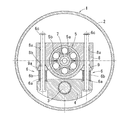
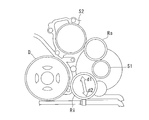
- FIG. 6 is a plan view of a state where an eccentric cam mechanism is added to the power transmission roller, and the power transmission state
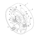
- FIG. 4 is a plan view of a state where an eccentric cam mechanism is provided along with a power transmission roller, in a power cut state Plan view showing the arrangement of each roller
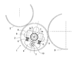
- Embodiments of the power transmission roller 1 according to the present invention are shown in FIGS. 1A to 5.
- the power transmission roller 1 is interposed between a driving roller D such as a crank and a driven roller S that operates auxiliary equipment such as a water pump (WP) and an idling stop generator (ISG).
- the rotational force is transmitted to the driven roller S side by a frictional force.
- the main component is a sliding member 9 that generates a frictional force with the shaft 6a of the member 6.
- the functions as the driving roller D and the driven roller S are not unique to each roller such as a crank.
- the ISG may function as the driving roller D and the crank may function as the driven roller S.
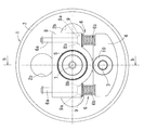
- the roller body 2 is a bottomed cylindrical member that is in direct contact with the driving roller D and the driven roller S.
- the contact surface of the roller body 2 with the driving roller D and the driven roller S is a knurled portion 2a for increasing the frictional force (see FIG. 2A).
- a plurality of holes 2b are formed in the cylindrical bottom portion of the roller body 2, and the weight of the roller body 2 is reduced.
- a bearing hole 2c is formed at the center of rotation of the roller body 2.
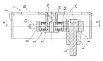
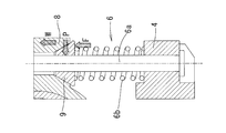
- the bearing holding member 7 By inserting the bearing holding member 7 into the inner ring 5a and the bearing hole 2c of the roller bearing 5 (in this embodiment, a ball bearing), the inner ring 5a side
- the roller main body 2 and the outer ring 5b of the roller bearing 5 are rotatable relative to each other (see FIG. 1B).
- the roller body 2 By configuring the roller body 2 to rotate together with the inner ring 5a, the load on the roller bearing 5 is reduced, and the life of the roller bearing 5 can be extended.
- the receiving member 8 is fitted into the outer ring 5b of the roller bearing 5.
- the receiving member 8 is formed with a pair of through holes 8 a and 8 a at symmetrical positions around the roller bearing 5.
- the shaft 6a of the urging member 6 is inserted into each through hole 8a, and the head side (the lower end side of the shaft 6a in FIG. 3) is swingably provided by the swing shaft 3. It is fixed to the arm 4.
- the tip end portion of the shaft 6a (the upper end side of the shaft 6a in FIG. 3) can be protruded from the receiving member 8 while being prevented from being detached by the retaining ring 6c.
- the coil spring 6b as an elastic body is provided coaxially with the shaft 6a.
- the coil spring 6b corresponds to the respective contact forces of the driving roller D and the driven roller S.
- Each of the coil springs 6b and 6b independently expands and contracts, and the swing arm 4 swings around the swing shaft 3 so that the roller body 2 is brought into contact with both the driving roller D and the driven roller S, Maintain contact.
- the biasing member 6 By configuring the biasing member 6 as a pair, the biasing member 6 is less likely to be twisted during biasing, and the power transmission roller 1 can be reliably brought into contact with the driving roller D and the driven roller S. It becomes. For this reason, power transmission by friction between the driving roller D and the driven roller S can be stably performed.
- the roller bearing 5 can be provided between the pair of urging members 6 and 6, and the stability of the roller bearing 5 during rotation can be ensured.
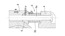
- the shaft 6 a is provided with a sliding member 9 interposed between the coil spring 6 b and the receiving member 8.
- An inclined surface 9 a with respect to the axial direction of the shaft 6 a is formed on the surface side of the sliding member 9 that contacts the receiving member 8.
- an inclined surface 8 b having the same inclination angle as the inclination angle of the inclined surface 9 a formed on the sliding member 9 is formed on the surface side of the receiving member 8 that contacts the sliding member 9.
- the sliding member When a material having flexibility such as a rubber material is used for the sliding member 9, the sliding member is produced to such an extent that a frictional force is generated between the sliding member 9 and the shaft 6 a even in a shape having no cut in the circumferential direction. 9 can be deformed, but when using a material such as a resin material or a metal material that is not easily deformed even when subjected to a biasing force from the coil spring 6b or a reaction force from the receiving member 8, a sliding member It is preferable that a notch is formed in a part of the circumferential direction 9 to have a C-shaped cross section, or a sliding member obtained by dividing the sliding member into a plurality of parts in the circumferential direction.
- the roller bearing 5 and the urging member 6 are disposed in a plane passing through the center in the width direction of the friction surface (knurling portion 2a) of the roller body 2.
- the oscillating shaft 3, the oscillating arm 4, the roller bearing 5, and the urging member 6 are all disposed on the inner diameter side (inside the cylinder) of the roller body 2. For this reason, size reduction of the power transmission mechanism including this power transmission roller 1 can be achieved.
- the power transmission roller 1 is configured such that the swing shaft 3 is fixed to a cover (not shown) that covers the driving roller D and the driven roller S via the spacer 10, and the cover is fitted into a predetermined position, thereby driving the driving roller. It is arranged at a predetermined position between D and the driven roller S.
- the power transmission roller 1 is provided with a mechanism (not shown) that can freely hold and release the biasing member 6 in a contracted state, so that the power transmission roller 1 and the driving roller can be fitted when the cover is fitted.
- the power transmission roller 1 can be attached easily and smoothly by preventing the contact between the D and the driven roller S.
- the power transmission roller 1 may be provided on the engine block.
- each of the coil springs 6b and 6b of the pair of urging members 6 and 6 is caused by the contact force.
- the swing arm 4 swings around the swing shaft 3. By this swinging, as shown in FIG. 6, the swinging arm 4 is displaced to a position corresponding to the position of each roller D, S, and between the driving roller D and the power transmission roller 1 and the driven roller S.
- the respective contact forces with the power transmission roller 1 are substantially equal, and power can be stably transmitted from the driving roller D to the driven roller S in this state.
- the driving roller D even when the driving roller D and the driven roller S are not completely perfect circles, and the self-excited vibration and resonance occur with the rotation, the driving roller D
- the contact state between the driven roller S and the roller body 2 can be stably maintained, and power can be reliably transmitted from the driving roller D to the driven roller S.
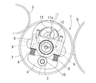
- an eccentric cam 11 that rotates around the eccentric shaft 11a can be provided in the vicinity of the roller bearing 5 of the power transmission roller 1 as shown in FIGS. 8A and 8B.
- the eccentric shaft 11a is connected to a motor (not shown) via a speed reduction mechanism 12 such as a planetary gear mechanism.
- a speed reduction mechanism 12 such as a planetary gear mechanism.
- the eccentric cam 11 abuts on the roller bearing 5 and resists the urging force of the urging member 6 provided on the power transmission roller 1 (so that the urging member 6 is compressed).
- the power transmission roller 1, the driving roller D, and the driven roller S are separated from each other (see FIG. 8B), and the power transmission from the driving roller D to the driven roller S is interrupted.
- the transmission and cutting of power between the driving roller D and the driven roller S can be performed easily and smoothly. Even if various actuators are employed in place of the eccentric cam 11 and the roller bearing 5 is pushed by this actuator, the same effect can be obtained. It should be noted that the roller bearing 5 is not necessarily pushed directly by the eccentric cam 11 but may be pushed via a pressing member (not shown) provided on the roller bearing 5. .
- the power transmission roller 1 according to the embodiment is merely an example, and the power transmission by friction between the driving roller D and the driven roller S is stably performed, and the power transmission mechanism is downsized. As long as the problems of the invention can be solved, it is allowed to change the shape and arrangement of each component part and to add additional parts.
Landscapes
- Engineering & Computer Science (AREA)
- General Engineering & Computer Science (AREA)
- Mechanical Engineering (AREA)
- Chemical & Material Sciences (AREA)
- Combustion & Propulsion (AREA)
- Friction Gearing (AREA)
Priority Applications (3)
| Application Number | Priority Date | Filing Date | Title |
|---|---|---|---|
| EP15855296.8A EP3214343B1 (en) | 2014-10-31 | 2015-10-23 | Power transmission roller assembly |
| US15/522,534 US10295027B2 (en) | 2014-10-31 | 2015-10-23 | Power transmission roller assembly |
| CN201580058579.XA CN107076281B (zh) | 2014-10-31 | 2015-10-23 | 传动辊 |
Applications Claiming Priority (2)
| Application Number | Priority Date | Filing Date | Title |
|---|---|---|---|
| JP2014222530A JP6352148B2 (ja) | 2014-10-31 | 2014-10-31 | 動力伝達ローラ |
| JP2014-222530 | 2014-10-31 |
Publications (1)
| Publication Number | Publication Date |
|---|---|
| WO2016068035A1 true WO2016068035A1 (ja) | 2016-05-06 |
Family
ID=55857374
Family Applications (1)
| Application Number | Title | Priority Date | Filing Date |
|---|---|---|---|
| PCT/JP2015/079943 WO2016068035A1 (ja) | 2014-10-31 | 2015-10-23 | 動力伝達ローラ |
Country Status (5)
| Country | Link |
|---|---|
| US (1) | US10295027B2 (ru) |
| EP (1) | EP3214343B1 (ru) |
| JP (1) | JP6352148B2 (ru) |
| CN (1) | CN107076281B (ru) |
| WO (1) | WO2016068035A1 (ru) |
Families Citing this family (2)
| Publication number | Priority date | Publication date | Assignee | Title |
|---|---|---|---|---|
| WO2017043638A1 (ja) * | 2015-09-09 | 2017-03-16 | Ntn株式会社 | フリクションホイールアッセンブリ、及び、その製造方法 |
| US10415676B1 (en) * | 2016-10-06 | 2019-09-17 | X Development Llc | Roller traction drive |
Citations (5)
| Publication number | Priority date | Publication date | Assignee | Title |
|---|---|---|---|---|
| JPS5126819Y2 (ru) * | 1972-05-26 | 1976-07-08 | ||
| JPH08277896A (ja) * | 1995-04-06 | 1996-10-22 | Mitsubishi Heavy Ind Ltd | トラクションドライブ装置 |
| JPH09296859A (ja) * | 1996-04-30 | 1997-11-18 | Ntn Corp | プーリユニット |
| JP2004044731A (ja) * | 2002-07-12 | 2004-02-12 | Nsk Ltd | 摩擦ローラ式変速機 |
| US20050181901A1 (en) * | 2004-02-13 | 2005-08-18 | Chang-Hyun Shin | Double action belt tensioner |
Family Cites Families (23)
| Publication number | Priority date | Publication date | Assignee | Title |
|---|---|---|---|---|
| US1806984A (en) * | 1931-05-26 | Variable speed transmission | ||
| US982104A (en) * | 1908-05-08 | 1911-01-17 | Mathurin Tarrisse | Frictional gearing. |
| US990844A (en) * | 1909-07-26 | 1911-05-02 | Martin B Covert | Frictional power-transmission mechanism. |
| US1870421A (en) | 1931-04-27 | 1932-08-09 | Herbert L Prout | System of friction gearing |
| US2031319A (en) * | 1935-05-03 | 1936-02-18 | Kahn Jacob Kesner | Belt drive |
| DE1030132B (de) * | 1955-07-06 | 1958-05-14 | Continental Gummi Werke Ag | Reibradgetriebe |
| JPH0437007A (ja) * | 1990-05-31 | 1992-02-07 | Matsushita Electric Ind Co Ltd | ガスレーザ発振装置 |
| JPH0674311A (ja) | 1992-08-27 | 1994-03-15 | Ricoh Co Ltd | 回転力伝達装置及びその使用方法 |
| US5931759A (en) * | 1997-05-09 | 1999-08-03 | Nsk Ltd. | Friction-roller speed changer |
| US6849025B2 (en) * | 2001-04-09 | 2005-02-01 | Nsk Ltd. | Frictional roller transmission |
| US6955621B2 (en) * | 2001-04-26 | 2005-10-18 | Borgwarner Inc. | Rotary actuating hydraulic tensioner |
| JP2004019727A (ja) * | 2002-06-13 | 2004-01-22 | Nsk Ltd | 摩擦ローラ式変速機 |
| DE10255074A1 (de) * | 2002-11-26 | 2004-06-03 | Bayerische Motoren Werke Ag | Riementrieb für Hilfsaggregate einer Brennkraftmaschine |
| DE10255079A1 (de) | 2002-11-26 | 2004-06-03 | Bayerische Motoren Werke Ag | Einem Aggregate-Riementrieb einer Brennkraftmaschine zugeordnetes Reibradgetriebe für ein gesondertes Nebenaggregat |
| DE10301758A1 (de) | 2003-01-18 | 2004-08-12 | Ina-Schaeffler Kg | Reibradantrieb |
| DE10309063A1 (de) * | 2003-03-03 | 2004-10-14 | Bayerische Motoren Werke Ag | Reibradgetriebe für ein von einem Aggregate-Riementrieb einer Brennkraftmaschine gesondert angeordnetes Nebenaggregat |
| ITMC20040092A1 (it) | 2004-07-09 | 2004-10-09 | So Ge Mi Spa | Motoriduttore elettrico per l'azionamento di una camma ad eccentrico |
| EP1819948B1 (en) | 2004-11-10 | 2008-12-31 | DAYCO EUROPE S.r.l. | A belt drive with a friction wheel |
| FR2884886B1 (fr) * | 2005-04-21 | 2009-04-17 | Renault Sas | Dispositif d'entrainement par friction d'un accessoire de moteur a combustion interne |
| JP4694520B2 (ja) * | 2007-03-07 | 2011-06-08 | 日産自動車株式会社 | 摩擦伝動変速装置 |
| EP2246592B1 (en) * | 2008-01-24 | 2012-08-29 | Nissan Motor Co., Ltd. | Friction-roller type transmission mechanism |
| JP2012092900A (ja) * | 2010-09-30 | 2012-05-17 | Aisin Seiki Co Ltd | 流体ポンプ |
| JP2012193793A (ja) * | 2011-03-16 | 2012-10-11 | Nsk Ltd | 摩擦ローラ式減速機及び電気自動車用駆動装置 |
-
2014
- 2014-10-31 JP JP2014222530A patent/JP6352148B2/ja not_active Expired - Fee Related
-
2015
- 2015-10-23 EP EP15855296.8A patent/EP3214343B1/en not_active Not-in-force
- 2015-10-23 WO PCT/JP2015/079943 patent/WO2016068035A1/ja active Application Filing
- 2015-10-23 CN CN201580058579.XA patent/CN107076281B/zh not_active Expired - Fee Related
- 2015-10-23 US US15/522,534 patent/US10295027B2/en not_active Expired - Fee Related
Patent Citations (5)
| Publication number | Priority date | Publication date | Assignee | Title |
|---|---|---|---|---|
| JPS5126819Y2 (ru) * | 1972-05-26 | 1976-07-08 | ||
| JPH08277896A (ja) * | 1995-04-06 | 1996-10-22 | Mitsubishi Heavy Ind Ltd | トラクションドライブ装置 |
| JPH09296859A (ja) * | 1996-04-30 | 1997-11-18 | Ntn Corp | プーリユニット |
| JP2004044731A (ja) * | 2002-07-12 | 2004-02-12 | Nsk Ltd | 摩擦ローラ式変速機 |
| US20050181901A1 (en) * | 2004-02-13 | 2005-08-18 | Chang-Hyun Shin | Double action belt tensioner |
Non-Patent Citations (1)
| Title |
|---|
| See also references of EP3214343A4 * |
Also Published As
| Publication number | Publication date |
|---|---|
| JP6352148B2 (ja) | 2018-07-04 |
| EP3214343B1 (en) | 2018-12-12 |
| US20170314653A1 (en) | 2017-11-02 |
| JP2016089886A (ja) | 2016-05-23 |
| CN107076281B (zh) | 2019-06-21 |
| EP3214343A4 (en) | 2017-10-11 |
| CN107076281A (zh) | 2017-08-18 |
| US10295027B2 (en) | 2019-05-21 |
| EP3214343A1 (en) | 2017-09-06 |
Similar Documents
| Publication | Publication Date | Title |
|---|---|---|
| EP3572301B1 (en) | Reducer of electric power steering apparatus | |
| JPWO2016038927A1 (ja) | 電動式パワーステアリング装置 | |
| TW201713880A (zh) | 離心離合器 | |
| TW201643331A (zh) | 離心離合器 | |
| BRPI0614853A2 (pt) | estágio de engrenagem | |
| WO2016068035A1 (ja) | 動力伝達ローラ | |
| WO2018083908A1 (ja) | 遠心クラッチ | |
| JP2019124361A (ja) | 遠心クラッチ | |
| JP2019199947A (ja) | 遠心クラッチ | |
| JP6552877B2 (ja) | 動力伝達ローラ | |
| WO2016043178A1 (ja) | 動力伝達ローラ | |
| WO2016076088A1 (ja) | 動力伝達ローラ | |
| WO2016043144A1 (ja) | 動力伝達ローラ | |
| JP2007211706A (ja) | 内燃機関の可変圧縮比機構 | |
| JP2018096213A (ja) | 内燃機関のバランス装置 | |
| JP2018076970A (ja) | 遠心クラッチ | |
| JP2016128699A (ja) | 動力伝達ローラ | |
| JP6510159B1 (ja) | 遠心クラッチ | |
| JP2018080647A (ja) | 内燃機関のバランス装置 | |
| JP2004084953A (ja) | 駆動力伝達装置 | |
| JP2018091430A (ja) | 内燃機関のバランス装置 | |
| JP2015147562A (ja) | 伸縮アクチュエータ | |
| JP6182358B2 (ja) | 動力伝達系のギヤ機構 | |
| JP5070689B2 (ja) | 連結ピン | |
| WO2016157281A1 (ja) | ベルト式無段変速機における従動プーリ構造 |
Legal Events
| Date | Code | Title | Description |
|---|---|---|---|
| 121 | Ep: the epo has been informed by wipo that ep was designated in this application |
Ref document number: 15855296 Country of ref document: EP Kind code of ref document: A1 |
|
| WWE | Wipo information: entry into national phase |
Ref document number: 15522534 Country of ref document: US |
|
| NENP | Non-entry into the national phase |
Ref country code: DE |
|
| REEP | Request for entry into the european phase |
Ref document number: 2015855296 Country of ref document: EP |