WO2016067574A1 - Dispositif de commande d'affichage et programme de commande d'affichage - Google Patents
Dispositif de commande d'affichage et programme de commande d'affichage Download PDFInfo
- Publication number
- WO2016067574A1 WO2016067574A1 PCT/JP2015/005335 JP2015005335W WO2016067574A1 WO 2016067574 A1 WO2016067574 A1 WO 2016067574A1 JP 2015005335 W JP2015005335 W JP 2015005335W WO 2016067574 A1 WO2016067574 A1 WO 2016067574A1
- Authority
- WO
- WIPO (PCT)
- Prior art keywords
- display
- image
- predetermined
- unit
- predetermined object
- Prior art date
Links
- 238000000034 method Methods 0.000 claims description 20
- 238000010586 diagram Methods 0.000 description 15
- 230000006870 function Effects 0.000 description 6
- 230000005540 biological transmission Effects 0.000 description 3
- 239000000470 constituent Substances 0.000 description 2
- 238000005516 engineering process Methods 0.000 description 2
- 239000004973 liquid crystal related substance Substances 0.000 description 2
- 230000004048 modification Effects 0.000 description 2
- 238000012986 modification Methods 0.000 description 2
- 239000003086 colorant Substances 0.000 description 1
- 238000004891 communication Methods 0.000 description 1
- 238000001514 detection method Methods 0.000 description 1
- 239000000284 extract Substances 0.000 description 1
- 238000010801 machine learning Methods 0.000 description 1
- 239000000463 material Substances 0.000 description 1
- 230000003287 optical effect Effects 0.000 description 1
- 229910052710 silicon Inorganic materials 0.000 description 1
- 239000010703 silicon Substances 0.000 description 1
- 239000007787 solid Substances 0.000 description 1
- 230000009466 transformation Effects 0.000 description 1
Images


Classifications
-
- G—PHYSICS
- G09—EDUCATION; CRYPTOGRAPHY; DISPLAY; ADVERTISING; SEALS
- G09G—ARRANGEMENTS OR CIRCUITS FOR CONTROL OF INDICATING DEVICES USING STATIC MEANS TO PRESENT VARIABLE INFORMATION
- G09G5/00—Control arrangements or circuits for visual indicators common to cathode-ray tube indicators and other visual indicators
- G09G5/36—Control arrangements or circuits for visual indicators common to cathode-ray tube indicators and other visual indicators characterised by the display of a graphic pattern, e.g. using an all-points-addressable [APA] memory
- G09G5/38—Control arrangements or circuits for visual indicators common to cathode-ray tube indicators and other visual indicators characterised by the display of a graphic pattern, e.g. using an all-points-addressable [APA] memory with means for controlling the display position
-
- B—PERFORMING OPERATIONS; TRANSPORTING
- B60—VEHICLES IN GENERAL
- B60K—ARRANGEMENT OR MOUNTING OF PROPULSION UNITS OR OF TRANSMISSIONS IN VEHICLES; ARRANGEMENT OR MOUNTING OF PLURAL DIVERSE PRIME-MOVERS IN VEHICLES; AUXILIARY DRIVES FOR VEHICLES; INSTRUMENTATION OR DASHBOARDS FOR VEHICLES; ARRANGEMENTS IN CONNECTION WITH COOLING, AIR INTAKE, GAS EXHAUST OR FUEL SUPPLY OF PROPULSION UNITS IN VEHICLES
- B60K35/00—Instruments specially adapted for vehicles; Arrangement of instruments in or on vehicles
- B60K35/10—Input arrangements, i.e. from user to vehicle, associated with vehicle functions or specially adapted therefor
-
- B—PERFORMING OPERATIONS; TRANSPORTING
- B60—VEHICLES IN GENERAL
- B60K—ARRANGEMENT OR MOUNTING OF PROPULSION UNITS OR OF TRANSMISSIONS IN VEHICLES; ARRANGEMENT OR MOUNTING OF PLURAL DIVERSE PRIME-MOVERS IN VEHICLES; AUXILIARY DRIVES FOR VEHICLES; INSTRUMENTATION OR DASHBOARDS FOR VEHICLES; ARRANGEMENTS IN CONNECTION WITH COOLING, AIR INTAKE, GAS EXHAUST OR FUEL SUPPLY OF PROPULSION UNITS IN VEHICLES
- B60K35/00—Instruments specially adapted for vehicles; Arrangement of instruments in or on vehicles
- B60K35/20—Output arrangements, i.e. from vehicle to user, associated with vehicle functions or specially adapted therefor
- B60K35/21—Output arrangements, i.e. from vehicle to user, associated with vehicle functions or specially adapted therefor using visual output, e.g. blinking lights or matrix displays
- B60K35/213—Virtual instruments
-
- B—PERFORMING OPERATIONS; TRANSPORTING
- B60—VEHICLES IN GENERAL
- B60K—ARRANGEMENT OR MOUNTING OF PROPULSION UNITS OR OF TRANSMISSIONS IN VEHICLES; ARRANGEMENT OR MOUNTING OF PLURAL DIVERSE PRIME-MOVERS IN VEHICLES; AUXILIARY DRIVES FOR VEHICLES; INSTRUMENTATION OR DASHBOARDS FOR VEHICLES; ARRANGEMENTS IN CONNECTION WITH COOLING, AIR INTAKE, GAS EXHAUST OR FUEL SUPPLY OF PROPULSION UNITS IN VEHICLES
- B60K35/00—Instruments specially adapted for vehicles; Arrangement of instruments in or on vehicles
- B60K35/20—Output arrangements, i.e. from vehicle to user, associated with vehicle functions or specially adapted therefor
- B60K35/21—Output arrangements, i.e. from vehicle to user, associated with vehicle functions or specially adapted therefor using visual output, e.g. blinking lights or matrix displays
- B60K35/23—Head-up displays [HUD]
-
- B—PERFORMING OPERATIONS; TRANSPORTING
- B60—VEHICLES IN GENERAL
- B60K—ARRANGEMENT OR MOUNTING OF PROPULSION UNITS OR OF TRANSMISSIONS IN VEHICLES; ARRANGEMENT OR MOUNTING OF PLURAL DIVERSE PRIME-MOVERS IN VEHICLES; AUXILIARY DRIVES FOR VEHICLES; INSTRUMENTATION OR DASHBOARDS FOR VEHICLES; ARRANGEMENTS IN CONNECTION WITH COOLING, AIR INTAKE, GAS EXHAUST OR FUEL SUPPLY OF PROPULSION UNITS IN VEHICLES
- B60K35/00—Instruments specially adapted for vehicles; Arrangement of instruments in or on vehicles
- B60K35/20—Output arrangements, i.e. from vehicle to user, associated with vehicle functions or specially adapted therefor
- B60K35/28—Output arrangements, i.e. from vehicle to user, associated with vehicle functions or specially adapted therefor characterised by the type of the output information, e.g. video entertainment or vehicle dynamics information; characterised by the purpose of the output information, e.g. for attracting the attention of the driver
- B60K35/285—Output arrangements, i.e. from vehicle to user, associated with vehicle functions or specially adapted therefor characterised by the type of the output information, e.g. video entertainment or vehicle dynamics information; characterised by the purpose of the output information, e.g. for attracting the attention of the driver for improving awareness by directing driver's gaze direction or eye points
-
- B—PERFORMING OPERATIONS; TRANSPORTING
- B60—VEHICLES IN GENERAL
- B60K—ARRANGEMENT OR MOUNTING OF PROPULSION UNITS OR OF TRANSMISSIONS IN VEHICLES; ARRANGEMENT OR MOUNTING OF PLURAL DIVERSE PRIME-MOVERS IN VEHICLES; AUXILIARY DRIVES FOR VEHICLES; INSTRUMENTATION OR DASHBOARDS FOR VEHICLES; ARRANGEMENTS IN CONNECTION WITH COOLING, AIR INTAKE, GAS EXHAUST OR FUEL SUPPLY OF PROPULSION UNITS IN VEHICLES
- B60K35/00—Instruments specially adapted for vehicles; Arrangement of instruments in or on vehicles
- B60K35/20—Output arrangements, i.e. from vehicle to user, associated with vehicle functions or specially adapted therefor
- B60K35/29—Instruments characterised by the way in which information is handled, e.g. showing information on plural displays or prioritising information according to driving conditions
-
- B—PERFORMING OPERATIONS; TRANSPORTING
- B60—VEHICLES IN GENERAL
- B60K—ARRANGEMENT OR MOUNTING OF PROPULSION UNITS OR OF TRANSMISSIONS IN VEHICLES; ARRANGEMENT OR MOUNTING OF PLURAL DIVERSE PRIME-MOVERS IN VEHICLES; AUXILIARY DRIVES FOR VEHICLES; INSTRUMENTATION OR DASHBOARDS FOR VEHICLES; ARRANGEMENTS IN CONNECTION WITH COOLING, AIR INTAKE, GAS EXHAUST OR FUEL SUPPLY OF PROPULSION UNITS IN VEHICLES
- B60K35/00—Instruments specially adapted for vehicles; Arrangement of instruments in or on vehicles
- B60K35/80—Arrangements for controlling instruments
- B60K35/81—Arrangements for controlling instruments for controlling displays
-
- G—PHYSICS
- G02—OPTICS
- G02B—OPTICAL ELEMENTS, SYSTEMS OR APPARATUS
- G02B27/00—Optical systems or apparatus not provided for by any of the groups G02B1/00 - G02B26/00, G02B30/00
- G02B27/01—Head-up displays
-
- G—PHYSICS
- G06—COMPUTING; CALCULATING OR COUNTING
- G06T—IMAGE DATA PROCESSING OR GENERATION, IN GENERAL
- G06T11/00—2D [Two Dimensional] image generation
- G06T11/60—Editing figures and text; Combining figures or text
-
- G—PHYSICS
- G06—COMPUTING; CALCULATING OR COUNTING
- G06V—IMAGE OR VIDEO RECOGNITION OR UNDERSTANDING
- G06V20/00—Scenes; Scene-specific elements
- G06V20/50—Context or environment of the image
- G06V20/56—Context or environment of the image exterior to a vehicle by using sensors mounted on the vehicle
-
- G—PHYSICS
- G09—EDUCATION; CRYPTOGRAPHY; DISPLAY; ADVERTISING; SEALS
- G09G—ARRANGEMENTS OR CIRCUITS FOR CONTROL OF INDICATING DEVICES USING STATIC MEANS TO PRESENT VARIABLE INFORMATION
- G09G5/00—Control arrangements or circuits for visual indicators common to cathode-ray tube indicators and other visual indicators
- G09G5/36—Control arrangements or circuits for visual indicators common to cathode-ray tube indicators and other visual indicators characterised by the display of a graphic pattern, e.g. using an all-points-addressable [APA] memory
- G09G5/37—Details of the operation on graphic patterns
- G09G5/377—Details of the operation on graphic patterns for mixing or overlaying two or more graphic patterns
-
- B—PERFORMING OPERATIONS; TRANSPORTING
- B60—VEHICLES IN GENERAL
- B60K—ARRANGEMENT OR MOUNTING OF PROPULSION UNITS OR OF TRANSMISSIONS IN VEHICLES; ARRANGEMENT OR MOUNTING OF PLURAL DIVERSE PRIME-MOVERS IN VEHICLES; AUXILIARY DRIVES FOR VEHICLES; INSTRUMENTATION OR DASHBOARDS FOR VEHICLES; ARRANGEMENTS IN CONNECTION WITH COOLING, AIR INTAKE, GAS EXHAUST OR FUEL SUPPLY OF PROPULSION UNITS IN VEHICLES
- B60K2360/00—Indexing scheme associated with groups B60K35/00 or B60K37/00 relating to details of instruments or dashboards
- B60K2360/149—Instrument input by detecting viewing direction not otherwise provided for
-
- B—PERFORMING OPERATIONS; TRANSPORTING
- B60—VEHICLES IN GENERAL
- B60K—ARRANGEMENT OR MOUNTING OF PROPULSION UNITS OR OF TRANSMISSIONS IN VEHICLES; ARRANGEMENT OR MOUNTING OF PLURAL DIVERSE PRIME-MOVERS IN VEHICLES; AUXILIARY DRIVES FOR VEHICLES; INSTRUMENTATION OR DASHBOARDS FOR VEHICLES; ARRANGEMENTS IN CONNECTION WITH COOLING, AIR INTAKE, GAS EXHAUST OR FUEL SUPPLY OF PROPULSION UNITS IN VEHICLES
- B60K2360/00—Indexing scheme associated with groups B60K35/00 or B60K37/00 relating to details of instruments or dashboards
- B60K2360/18—Information management
-
- B—PERFORMING OPERATIONS; TRANSPORTING
- B60—VEHICLES IN GENERAL
- B60K—ARRANGEMENT OR MOUNTING OF PROPULSION UNITS OR OF TRANSMISSIONS IN VEHICLES; ARRANGEMENT OR MOUNTING OF PLURAL DIVERSE PRIME-MOVERS IN VEHICLES; AUXILIARY DRIVES FOR VEHICLES; INSTRUMENTATION OR DASHBOARDS FOR VEHICLES; ARRANGEMENTS IN CONNECTION WITH COOLING, AIR INTAKE, GAS EXHAUST OR FUEL SUPPLY OF PROPULSION UNITS IN VEHICLES
- B60K2360/00—Indexing scheme associated with groups B60K35/00 or B60K37/00 relating to details of instruments or dashboards
- B60K2360/20—Optical features of instruments
- B60K2360/33—Illumination features
- B60K2360/334—Projection means
-
- B—PERFORMING OPERATIONS; TRANSPORTING
- B60—VEHICLES IN GENERAL
- B60K—ARRANGEMENT OR MOUNTING OF PROPULSION UNITS OR OF TRANSMISSIONS IN VEHICLES; ARRANGEMENT OR MOUNTING OF PLURAL DIVERSE PRIME-MOVERS IN VEHICLES; AUXILIARY DRIVES FOR VEHICLES; INSTRUMENTATION OR DASHBOARDS FOR VEHICLES; ARRANGEMENTS IN CONNECTION WITH COOLING, AIR INTAKE, GAS EXHAUST OR FUEL SUPPLY OF PROPULSION UNITS IN VEHICLES
- B60K2360/00—Indexing scheme associated with groups B60K35/00 or B60K37/00 relating to details of instruments or dashboards
- B60K2360/20—Optical features of instruments
- B60K2360/33—Illumination features
- B60K2360/343—Illumination of matrix displays
- B60K2360/344—Illumination of matrix displays for additionally illuminating mechanical elements, e.g. pointers or control knobs
-
- B—PERFORMING OPERATIONS; TRANSPORTING
- B60—VEHICLES IN GENERAL
- B60R—VEHICLES, VEHICLE FITTINGS, OR VEHICLE PARTS, NOT OTHERWISE PROVIDED FOR
- B60R2300/00—Details of viewing arrangements using cameras and displays, specially adapted for use in a vehicle
- B60R2300/20—Details of viewing arrangements using cameras and displays, specially adapted for use in a vehicle characterised by the type of display used
- B60R2300/205—Details of viewing arrangements using cameras and displays, specially adapted for use in a vehicle characterised by the type of display used using a head-up display
-
- B—PERFORMING OPERATIONS; TRANSPORTING
- B60—VEHICLES IN GENERAL
- B60R—VEHICLES, VEHICLE FITTINGS, OR VEHICLE PARTS, NOT OTHERWISE PROVIDED FOR
- B60R2300/00—Details of viewing arrangements using cameras and displays, specially adapted for use in a vehicle
- B60R2300/30—Details of viewing arrangements using cameras and displays, specially adapted for use in a vehicle characterised by the type of image processing
- B60R2300/301—Details of viewing arrangements using cameras and displays, specially adapted for use in a vehicle characterised by the type of image processing combining image information with other obstacle sensor information, e.g. using RADAR/LIDAR/SONAR sensors for estimating risk of collision
-
- B—PERFORMING OPERATIONS; TRANSPORTING
- B60—VEHICLES IN GENERAL
- B60R—VEHICLES, VEHICLE FITTINGS, OR VEHICLE PARTS, NOT OTHERWISE PROVIDED FOR
- B60R2300/00—Details of viewing arrangements using cameras and displays, specially adapted for use in a vehicle
- B60R2300/30—Details of viewing arrangements using cameras and displays, specially adapted for use in a vehicle characterised by the type of image processing
- B60R2300/307—Details of viewing arrangements using cameras and displays, specially adapted for use in a vehicle characterised by the type of image processing virtually distinguishing relevant parts of a scene from the background of the scene
- B60R2300/308—Details of viewing arrangements using cameras and displays, specially adapted for use in a vehicle characterised by the type of image processing virtually distinguishing relevant parts of a scene from the background of the scene by overlaying the real scene, e.g. through a head-up display on the windscreen
-
- B—PERFORMING OPERATIONS; TRANSPORTING
- B60—VEHICLES IN GENERAL
- B60W—CONJOINT CONTROL OF VEHICLE SUB-UNITS OF DIFFERENT TYPE OR DIFFERENT FUNCTION; CONTROL SYSTEMS SPECIALLY ADAPTED FOR HYBRID VEHICLES; ROAD VEHICLE DRIVE CONTROL SYSTEMS FOR PURPOSES NOT RELATED TO THE CONTROL OF A PARTICULAR SUB-UNIT
- B60W50/00—Details of control systems for road vehicle drive control not related to the control of a particular sub-unit, e.g. process diagnostic or vehicle driver interfaces
- B60W2050/0001—Details of the control system
- B60W2050/0043—Signal treatments, identification of variables or parameters, parameter estimation or state estimation
-
- G—PHYSICS
- G02—OPTICS
- G02B—OPTICAL ELEMENTS, SYSTEMS OR APPARATUS
- G02B27/00—Optical systems or apparatus not provided for by any of the groups G02B1/00 - G02B26/00, G02B30/00
- G02B27/01—Head-up displays
- G02B27/0101—Head-up displays characterised by optical features
- G02B2027/0138—Head-up displays characterised by optical features comprising image capture systems, e.g. camera
-
- G—PHYSICS
- G02—OPTICS
- G02B—OPTICAL ELEMENTS, SYSTEMS OR APPARATUS
- G02B27/00—Optical systems or apparatus not provided for by any of the groups G02B1/00 - G02B26/00, G02B30/00
- G02B27/01—Head-up displays
- G02B27/0101—Head-up displays characterised by optical features
- G02B2027/014—Head-up displays characterised by optical features comprising information/image processing systems
-
- G—PHYSICS
- G02—OPTICS
- G02B—OPTICAL ELEMENTS, SYSTEMS OR APPARATUS
- G02B27/00—Optical systems or apparatus not provided for by any of the groups G02B1/00 - G02B26/00, G02B30/00
- G02B27/01—Head-up displays
- G02B27/0101—Head-up displays characterised by optical features
- G02B2027/0141—Head-up displays characterised by optical features characterised by the informative content of the display
-
- G—PHYSICS
- G02—OPTICS
- G02B—OPTICAL ELEMENTS, SYSTEMS OR APPARATUS
- G02B27/00—Optical systems or apparatus not provided for by any of the groups G02B1/00 - G02B26/00, G02B30/00
- G02B27/01—Head-up displays
- G02B27/0179—Display position adjusting means not related to the information to be displayed
- G02B2027/0181—Adaptation to the pilot/driver
-
- G—PHYSICS
- G02—OPTICS
- G02B—OPTICAL ELEMENTS, SYSTEMS OR APPARATUS
- G02B27/00—Optical systems or apparatus not provided for by any of the groups G02B1/00 - G02B26/00, G02B30/00
- G02B27/01—Head-up displays
- G02B2027/0192—Supplementary details
- G02B2027/0198—System for aligning or maintaining alignment of an image in a predetermined direction
-
- G—PHYSICS
- G02—OPTICS
- G02B—OPTICAL ELEMENTS, SYSTEMS OR APPARATUS
- G02B27/00—Optical systems or apparatus not provided for by any of the groups G02B1/00 - G02B26/00, G02B30/00
- G02B27/01—Head-up displays
- G02B27/0101—Head-up displays characterised by optical features
-
- G—PHYSICS
- G09—EDUCATION; CRYPTOGRAPHY; DISPLAY; ADVERTISING; SEALS
- G09G—ARRANGEMENTS OR CIRCUITS FOR CONTROL OF INDICATING DEVICES USING STATIC MEANS TO PRESENT VARIABLE INFORMATION
- G09G2320/00—Control of display operating conditions
- G09G2320/10—Special adaptations of display systems for operation with variable images
-
- G—PHYSICS
- G09—EDUCATION; CRYPTOGRAPHY; DISPLAY; ADVERTISING; SEALS
- G09G—ARRANGEMENTS OR CIRCUITS FOR CONTROL OF INDICATING DEVICES USING STATIC MEANS TO PRESENT VARIABLE INFORMATION
- G09G2340/00—Aspects of display data processing
- G09G2340/12—Overlay of images, i.e. displayed pixel being the result of switching between the corresponding input pixels
-
- G—PHYSICS
- G09—EDUCATION; CRYPTOGRAPHY; DISPLAY; ADVERTISING; SEALS
- G09G—ARRANGEMENTS OR CIRCUITS FOR CONTROL OF INDICATING DEVICES USING STATIC MEANS TO PRESENT VARIABLE INFORMATION
- G09G2380/00—Specific applications
- G09G2380/10—Automotive applications
Definitions
- the present invention relates to a display control device and a display control program for controlling display of information provided to a passenger such as a vehicle.
- HUD Head-Up Display
- an image including navigation information or the like is projected onto a windshield or the like of the vehicle, and a virtual image by reflected light is visually recognized by a driver of the vehicle.
- the driver recognizes navigation information or the like as a virtual image superimposed on the real scenery seen through the windshield in one field of view together with the real scenery. If navigation information or the like is displayed at an appropriate position corresponding to each element (for example, a display on a road, a building, etc.) on the actual scenery with HUD, the driver can easily recognize the navigation information and the like.
- the HUD display is displayed in correspondence with a desired position on the actual landscape
- the height of the driver's viewpoint position varies depending on the setting of the driver's seat height, the seat back angle, etc.
- the virtual image position in the vertical direction when viewed from the driver's viewpoint changes.
- the virtual image position is a depression angle when the virtual image is viewed from the driver's viewpoint.
- Patent Document 1 As a method of changing the information presentation to the driver according to the height of the driver's viewpoint, there is a technique disclosed in Patent Document 1, for example.
- Patent Literature 1 includes a first display object displayed in correspondence with the position of a target ahead of the vehicle, and a second display object that has a different content from the first display object and is displayed at a different position.
- Video data including the first display object and the second display object is changed according to the difference in height of the driver's viewpoint. Thereby, even if the height of the driver's viewpoint is different, it is possible to easily superimpose the display content at a desired position on the actual landscape.
- Patent Document 2 discloses a related technique.
- JP 2011-123119 A Japanese Patent Laid-Open No. 7-257228
- the present invention relates to a display control device and a display control program capable of presenting useful information to an occupant even when the viewpoint height of the occupant (for example, a driver) of a moving body such as a vehicle fluctuates. I will provide a.
- the display control device is a display control device in a display system including a recognition unit, a display unit, and an estimation unit.
- the recognition unit recognizes a predetermined object existing in the foreground of the moving object.
- the display unit generates a predetermined image based on the recognition result of the recognition unit, and displays the predetermined image on the display medium, thereby causing the occupant of the moving body to visually recognize the virtual image.
- the estimation unit estimates a depression angle when a virtual image is viewed from the occupant.
- the display control device includes a determination unit and a control unit.
- the determination unit determines whether or not the predetermined object viewed from the occupant falls within the virtual image display range based on the position information of the predetermined object acquired from the recognition unit and the estimated depression angle acquired from the estimation unit. Determine.
- the control unit displays a first presentation image indicating information corresponding to the predetermined object when displayed on the display medium.
- the display unit is controlled to generate a first predetermined image to be represented.
- the determination unit determines that the predetermined object does not fall within the display range, the information corresponding to the predetermined object is different from the first presentation image when displayed on the display medium.
- the display unit is controlled so as to generate a second predetermined image representing the second presentation image shown in the aspect.
- the display control program is executed by a computer in the display system.
- This program causes the computer to execute the following processing.
- a first predetermined image representing a first presentation image indicating information regarding the predetermined object is generated when displayed on the display medium.
- the display is performed. Processing for controlling the display unit so as to generate a second predetermined image representing a second presentation image indicating information related to the predetermined object in a mode different from the first presentation image when displayed on the medium .
- the present invention it is possible to present useful information to the occupant even when the height of the viewpoint of the occupant of the moving body fluctuates.
- FIG. 1A is a diagram illustrating a positional relationship (in the case of a high viewpoint) between an actual scenery in front of the vehicle seen by the driver of the vehicle and a display range of the HUD.
- FIG. 1B is a diagram showing a positional relationship (in the case of a standard height viewpoint) between the actual scenery in front of the vehicle seen by the driver of the vehicle and the display range of the HUD.
- FIG. 1C is a diagram showing a positional relationship (in the case of a low viewpoint) between the actual scenery in front of the vehicle seen by the driver of the vehicle and the display range of the HUD.
- FIG. 2 is a schematic diagram illustrating a configuration example of the display system according to the embodiment.
- FIG. 1A is a diagram illustrating a positional relationship (in the case of a high viewpoint) between an actual scenery in front of the vehicle seen by the driver of the vehicle and a display range of the HUD.
- FIG. 1B is a diagram showing a positional relationship (in the case of
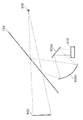
- FIG. 3 is a diagram illustrating a state where a predetermined object falls within the display range of the HUD.
- FIG. 4 is a diagram illustrating a state in which a predetermined object does not fall within the HUD display range.
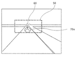
- FIG. 5 is a diagram illustrating an example of the view from the viewpoint of the driver (when a predetermined object falls within the display range of the HUD).
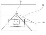
- FIG. 6 is a diagram illustrating an example of a view from the viewpoint of the driver (when a predetermined object does not fall within the display range of the HUD).
- FIG. 7 is a configuration diagram illustrating the configuration of the display unit.
- FIG. 8 is a conceptual diagram showing the adjustment of the mirror angle of the display unit.
- FIG. 9 is a flowchart showing display control processing by the display control apparatus.
- FIG. 9 is a flowchart showing display control processing by the display control apparatus.
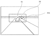
- FIG. 10 is a diagram illustrating an example of the view from the viewpoint of the driver (when the intersection falls within the display range of the HUD).
- FIG. 11 is a diagram illustrating an example of the view from the viewpoint of the driver (when the intersection does not fall within the display range of the HUD).
- FIG. 12 is a flowchart illustrating a modification of the display control process.
- FIGS. 1A to 1C are views showing the positional relationship between the actual scenery in front of the vehicle seen by the driver of the vehicle and the display range 50 of the HUD.
- FIG. 1A shows an example of a driver's field of view having a higher viewpoint than the standard viewpoint
- FIG. 1B shows an example of a driver's field of view having the same height as the standard viewpoint
- FIG. An example of a driver's field of view having a lower viewpoint than the standard viewpoint is shown.
- FIG. 2 is a schematic diagram illustrating a configuration example of the display system 10 according to the first embodiment of the present invention. First, a configuration example of the display system 10 according to the present embodiment will be described.
- the display system 10 is mounted on a moving body such as a vehicle, for example, and projects an image representing information onto a display medium such as a windshield 700 to visually recognize a virtual image 800 that reflects the information on a passenger of the moving body having a viewpoint 900.
- the display system includes a display unit (for example, HUD or the like).
- the display system 10 displays information as a virtual image in the occupant's field of view so as to overlap with a real landscape or the like.
- the display system 10 is described as being applied to a vehicle.
- the moving body is not limited to a vehicle, and may be a ship, an aircraft, or the like.
- the display range of the virtual image displayed in the occupant's field of view by the projection of the display unit described above is physically limited to a certain range depending on the arrangement and structure of the display unit. Is done.
- the display range of the virtual image is also referred to as a HUD display range here.
- the display system 10 includes a sensor 100, a recognition unit 200, an estimation unit 300, a display control device 20 (determination unit 400 and control unit 500), a display unit 600, and a windshield (display medium) 700. .
- the sensor 100 is mounted inside or outside the vehicle, and sequentially senses the foreground of the driver of the vehicle (for example, every predetermined time such as several hundred milliseconds or several tens of milliseconds).
- the sensor 100 is an image sensor (camera) that detects foreground light or the like, for example.
- the sensor 100 only needs to detect the foreground state of the driver of the vehicle.
- the sensor 100 may be a radar that detects reflection of electromagnetic waves.
- the sensor 100 transmits foreground information indicating the result of foreground sensing to the recognition unit 200. This output is performed at predetermined time intervals, for example.
- the recognition unit 200 Based on the foreground information transmitted from the sensor 100, the recognition unit 200 recognizes a predetermined object existing around the vehicle (for example, within about 100 m ahead) in the foreground of the driver of the vehicle, and a recognition result indicating the recognition result. Output information.
- the predetermined target object to be recognized is, for example, a moving body (for example, a vehicle, a person, a bicycle, a two-wheeled vehicle, etc.), a road sign, a white line on the road, a road marking, a curb, a guardrail, a traffic light, a power pole, and a building.
- the recognition unit 200 recognizes an object by performing image processing such as pattern matching on the foreground information (that is, the foreground image captured by the camera). For example, when the sensor 100 is a radar, the recognition unit 200 extracts and recognizes an object from the foreground information by clustering or machine learning. Since the object recognition technique in the recognition unit 200 is a well-known technique, a detailed description thereof is omitted here.
- the recognition result information output by the recognition unit 200 is, for example, the presence position (X, Y) of a predetermined object. When there are a plurality of types of predetermined objects (mobile objects, road signs, etc.), the recognition result information may be information in which the types of the predetermined objects are associated with their positions.
- the presence position (X, Y) of the predetermined object is, for example, the driver's left and right (lateral) direction as the front and rear, with respect to the point where the sensing camera is installed so as to capture the foreground of the driver of the vehicle This is a coordinate in the camera coordinate system with the direction as the Y axis.
- Y at the position (X, Y) of the predetermined object indicates, for example, the distance between the vehicle and the predetermined object in the traveling direction of the vehicle.
- the estimation unit 300 estimates the depression angle when viewing a virtual image (image displayed by the display unit 600) from the viewpoint of the driver, and outputs the estimated value. Specifically, the depression angle value at each viewpoint position is held in advance, and the depression angle is estimated by detecting the position of the driver's viewpoint with a camera (not shown).
- the depression angle is not limited to this method.
- the position of the driver's viewpoint may be estimated from the angle of the mirror provided in the display unit 600, and the depression angle may be estimated based on the result. .
- Each function of the recognition unit 200 and the estimation unit 300 described above is stored in a memory in a computer or the like including a memory and a processor (CPU (Central Processing Unit)), for example.
- CPU Central Processing Unit
- the recognition unit 200 outputs recognition result information sequentially (for example, every predetermined time such as several hundred milliseconds or several tens of milliseconds) corresponding to the sensing of the sensor 100.
- the estimated value of the depression angle is output by the estimation unit 300 once at a suitable time (such as when the display system 10 is activated) or at regular intervals (for example, several seconds or several hundred milliseconds).
- the display control device 20 acquires information output from the recognition unit 200 and the estimation unit 300, sequentially (for example, every predetermined time such as several hundred milliseconds, tens of milliseconds, etc.), and display (projection on a display medium).
- the display unit 600 is controlled to generate a target image.
- the display control device 20 is realized in terms of hardware by, for example, a known computer including a memory and a processor, and includes a determination unit 400 and a control unit 500 as functional components. Each function of the determination unit 400 and the control unit 500 is realized by the processor executing a control program stored in the memory.
- the memory is a ROM (Read Only Memory) that holds programs and data in advance, a RAM (Random Access Memory) that is used to store data during program execution, and includes, for example, a non-volatile memory You may go out.
- the determination unit 400 obtains the recognition result information output from the recognition unit 200 and the estimated depression angle output from the estimation unit 300, and based on the recognition result information and the estimated depression angle, the predetermined result indicated by the recognition result information. It is determined whether or not the target object falls within the display range of the HUD.
- the distance range such as the foreground road surface that falls within the display range of the HUD varies depending on the depression angle of the driver. Specifically, as illustrated in FIG. 3, the determination unit 400 determines that the predetermined object 60 is obtained when a straight line connecting the driver's viewpoint 900 and the predetermined object 60 passes through the display range of the virtual image 800. Is within the display range of the HUD.
- FIG. 3 the determination unit 400 determines that the predetermined object 60 is obtained when a straight line connecting the driver's viewpoint 900 and the predetermined object 60 passes through the display range of the virtual image 800. Is within the display range of the HUD.
- the predetermined object 60 is within the display range of the HUD. Judge that it is not in.
- the driver's viewpoint 900 is at a position having a depression angle 51a as shown in FIG. 3 and when the driver's viewpoint 900 is at a position having a depression angle 51b larger than the depression angle 51a as shown in FIG.
- Whether or not the predetermined object 60 is visually recognized within the display range of the HUD is different.
- the determination unit 400 surrounds the predetermined object 60 in a virtual image that is displayed superimposed on the real landscape. It may be determined whether or not the display position of the display object set to be displayed is within the display range of the HUD.
- the determination unit 400 transmits determination result information indicating the determination result to the control unit 500.
- the control unit 500 controls the display unit 600 so as to generate an image to be projected on the windshield 700, that is, an image to be displayed as a virtual image. Specifically, based on the determination result information transmitted from the determination unit 400, the control unit 500 displays different images depending on whether the predetermined object 60 is within the HUD display range or not.
- the display unit 600 is controlled to be generated at 600.
- the control unit 500 displays the predetermined object on the actual scene as shown in FIG. 5 when displayed on the display medium.
- the display unit 600 is controlled so as to generate a predetermined image representing an image in which a display object is superimposed on the target object 60.
- the control unit 500 controls the display unit 600 so as to generate a predetermined image representing an image displayed in the display range 50 of the HUD when displayed on the display medium.
- the display object is a component of an image (that is, an image element) formed by a mark such as a character string, a symbol, a figure, or an image, and is predetermined.
- the display object represents a warning that alerts the driver regarding the predetermined object 60.
- FIG. 5 shows a view from the viewpoint of the driver having the depression angle 51a shown in FIG. 3, for example.
- a person as a predetermined object 60 appears in the actual landscape, and an elliptical display object 70 a is displayed in the HUD display range 50 so as to be superimposed on the person. Since the display object 70a emphasizes the presence of a person (predetermined object 60) as a matter to be noted in driving, the driver of the vehicle can accurately recognize the predetermined object 60.
- the control unit 500 displays the actual scenery as shown in FIG. 6 when displayed on the display medium.
- the display unit 600 is controlled so as to generate a predetermined image representing an image that indirectly represents the position of the predetermined object 60 above.
- the predetermined object 60 does not fall within the display range of the HUD as viewed from the driver's viewpoint, and the display object is displayed superimposed on the predetermined object 60. Since an image cannot be generated, an image representing the position of the predetermined object 60 with a mark such as an arrow is generated.
- FIG. 6 shows, for example, a view from the viewpoint of the driver having the depression angle 51b shown in FIG. 6 is the same as FIG. 5 in that a person appears as the predetermined object 60 in the real scene, but since the person does not enter the display range 50 of the HUD, an arrow indicating the direction of the position of the person And a display object 70b including a character string for calling attention.
- the control unit 500 when it is determined that the predetermined object 60 does not fall within the display range of the HUD, the control unit 500 generates an image including a display object that indirectly represents the position of the object.
- the display object is not limited to the display object that indirectly represents the position of the target object, but may be any display object that allows the driver to recognize that it is associated with the predetermined target object 60. Good. The driver can accurately recognize the predetermined object 60 by the display object.
- the display unit 600 generates a predetermined image under the control of the control unit 500 and projects the image onto the windshield 700.
- a configuration example of the display unit 600 is shown in FIG.
- the display unit 600 includes, for example, an LCD (Liquid Crystal Display) 610, a plane mirror 620a and a concave mirror 620b, and an image generation unit (not shown) that generates an image.
- the image is displayed on LCD 610.
- the image displayed on the LCD 610 is reflected by the plane mirror 620a, enlarged by the concave mirror 620b, and projected onto the windshield 700.
- the image enlarged and projected on the windshield 700 is visually recognized as a virtual image 800 by the driver.
- the virtual image 800 is displayed so as to be superimposed on a real landscape or the like that is visible in the driver's field of view.
- the virtual image 800 is recognized by the driver so as to appear at a position (for example, 2 m to 3 m ahead) at which the line of sight is focused during driving.
- the height of the driver's viewpoint 900 varies depending on the driver's seat height, the angle of the seat back, and the like.
- an adjustment unit (not shown) that adjusts the angle of the concave mirror 620b by driving a motor or the like is provided.
- FIG. 8 is a conceptual diagram illustrating adjustment of the mirror angle of the display unit 600. As shown in FIG. 8, by adjusting the angle of the concave mirror 620b, both when the seat height is high (solid line in FIG. 8) and when the seat height is low (dashed line in FIG. 8), from the viewpoint of the driver. A virtual image can be visually recognized.
- the angle of the concave mirror 620b may be adjusted by, for example, detecting the position of the driver's viewpoint with a camera (not shown) and adjusting based on the detection result, or providing an adjustment switch (not shown) by the driver. You may make it adjust according to operation of the switch for adjustment.
- the recognition unit 200 recognizes a predetermined object according to the foreground information from the sensor 100 every predetermined time, and outputs authentication result information indicating the position of the object.
- the estimation unit 300 operates based on the position of the driver's viewpoint detected by a camera (not shown) or the adjusted angle of the mirror (concave mirror 620b, etc.) of the display unit 600.
- the depression angle at the person's viewpoint is estimated, and the estimated depression angle is output.
- the display control device 20 executes display control processing for generating an image, and the generated image is displayed on the display unit 600.
- FIG. 9 is a flowchart showing display control processing by the display control apparatus 20 according to the present embodiment.
- This display control process is repeatedly executed at a predetermined cycle. This period is related to the frame rate at which a predetermined image is supplied to the display unit 600 (LCD 610), and is, for example, several hundred milliseconds or several tens of milliseconds.
- the determination unit 400 of the display control device 20 acquires the estimated value of the depression angle output by the estimation unit 300 (step S1). Moreover, the determination part 400 acquires the positional information on a predetermined target object by acquiring the recognition result information which the recognition part 200 output (step S2).
- the determination unit 400 determines whether or not the predetermined object viewed from the driver falls within the virtual image display range, that is, the HUD display range 50 based on the acquired estimated depression angle value and position information of the predetermined object. Is determined (step S3). Determination result information indicating the determination result is transmitted to the control unit 500.
- the control unit 500 is displayed on the display medium.
- the display unit 600 generates a first predetermined image representing a first display object (first presentation image) indicating information corresponding to the predetermined object at the position of the predetermined object as viewed from the driver. (Step S4), and the display unit 600 generates a first predetermined image.
- the predetermined image is, for example, an image of a predetermined size to be displayed on the LCD 610, and the luminance is a predetermined low luminance value (for example, 0) so that the portion where the display object is not arranged is not displayed.
- the first display object is, for example, the above-described display object 70a indicating information (for example, an oval figure) corresponding to the predetermined object 60 (see FIG. 5).
- the position of the first display object in the predetermined image is calculated as a position overlapping the predetermined object as viewed from the driver based on the recognition result information and the estimated depression angle.
- the recognition result information includes a predetermined object type
- the content of information (for example, the shape of a figure) indicated by the display object arranged in the predetermined image for each type may be set in advance.
- step S3 when the determination unit 400 determines that the predetermined object does not fall within the HUD display range 50 (no in step S3), the control unit 500 displays the image on the display medium.
- a second predetermined object representing a second display object (second presentation image) indicating information corresponding to the predetermined object at a position closer to the position of the predetermined object as viewed from the driver than the center of the display range.
- the display unit 600 is controlled to generate an image (step S5), and the display unit 600 generates a second predetermined image.
- the second display object is different in display form from the first display object, for example, the information corresponding to the predetermined object 60 (for example, a combination of a graphic of an arrow and a character string of “Caution” that calls attention) is described above.
- the display object 70b (see FIG. 6).
- the position of the second display object in the predetermined image is shifted (moved) in the direction of the predetermined object as viewed from the driver, based on the recognition result information and the estimated value of the depression angle, compared to the case where the second display object is arranged at the center of the predetermined image. Calculated to position.
- the shift amount is arbitrary, but may be shifted by a maximum shiftable amount, for example. In the example of FIG. 6, it is shifted upward. This shift makes it easier for the driver to recognize that the second display object is associated with a predetermined object.
- the display unit 600 projects the generated first or second predetermined image on the display medium under the control of the control unit 500 in step S4 or step S5.
- the configuration of the optical system such as a mirror or a lens in the display unit 600 described above may be other than that shown in FIG.
- the image output means in the display unit 600 may be other than the LCD (for example, a laser projector, LCOS (Liquid Crystal on Silicon), etc.).
- the display unit 600 projects an image on the windshield 700, but may project the image onto a combiner that is a half mirror provided separately from the windshield 700. Further, the display unit 600 may display an image on a transmissive display provided inside or on the surface of the windshield 700.
- step S5 of the display control process described above the second display object is shifted in the direction of the predetermined target.
- the second display object may not be necessarily shifted, and the second display object may be arbitrarily set in the predetermined image. You may arrange
- the second display object described above is not limited to the display object 70b including a specific mark (such as an arrow graphic) representing the position of the predetermined object, and does not indicate the position of the predetermined object. It may be.
- the first display object may be arranged around the predetermined object in addition to being arranged at a position overlapping the predetermined object. When the first display object is displayed at a position superimposed on a predetermined object, it is not necessary to indicate the position, and therefore it is not necessary to include a specific mark representing the position.
- a specific mark an arrow figure or the like representing the position of the predetermined target object may be included in the first display object.
- the above-described recognition unit 200 may simultaneously recognize a plurality of predetermined objects, and each of the plurality of predetermined objects is determined by the determination unit 400 and the display object (first object) by the control unit 500.
- generation control of the second display object) and generation of a predetermined image by the display unit 600 may be performed.
- the predetermined image described above may include display objects representing various information (speed and other information) necessary for driving.
- information may be transmitted to the driver by voice from a speaker or the like mounted on the vehicle.
- different sounds may be output when the first display object is displayed and when the second display object is displayed.
- first display object and the second display object described above may have different colors, brightness, and the like.
- the execution order of the display control processing procedure (see FIG. 9) in the display control device 20 described above is not necessarily limited to the order described above, and the execution order is within the scope of the invention. Can be replaced or a part of them can be omitted.
- all or part of the above-described display control processing procedure may be realized by hardware, may be realized using software, or may be realized by a combination of both software and hardware.
- the processing by software is realized by a processor included in a computer or the like executing a display control program stored in a memory.
- the display control program may be recorded on a recording medium and distributed or distributed. For example, by installing a distributed display control program in a device having a processor and causing the processor of the device to execute the program, it is possible to cause the device to perform all or part of the display control processing.
- the computer described above may include an input device, an output device, a reading device that reads information from a recording medium, or a transmission / reception device that performs communication via a network, although it is not essential.
- the input device is, for example, an input button or a touch pad.
- the output device is, for example, a display or a speaker.
- the recording medium is, for example, a storage device such as a hard disk device or an SSD (Solid State Drive), a DVD-ROM (Digital Versatile Disk Read Only Memory), or a USB (Universal Serial Bus) memory.
- the display control program described above is recorded on a recording medium such as a USB memory
- the reading device reads the display control program and stores it in a memory or other storage device.
- the transmission / reception device may communicate with an external server device storing the display control program via a network, download the display control program from the server device, and store it in a memory or other storage device.
- the display control device 20 may be configured as an integrated circuit.
- the display system 10 (the display control device 20 or the like), information useful to the occupant even when the fluctuation range of the viewpoint height of the occupant (such as a driver) of a moving body such as a vehicle is large. Can be presented.
- This modified display system includes a sensor 100, a recognition unit 200, an estimation unit 300, a modified display control device, a display unit 600, and a windshield 700.
- the same components as those in the first embodiment are denoted by the same reference numerals as those in the first embodiment, and detailed description thereof is omitted here.
- the modified display control apparatus has a configuration in which a navigation function of a vehicle based on positioning information and map data based on GPS (Global Positioning System) is added to the display control apparatus 20 shown in the first embodiment.
- the modified display control device includes a computer including a memory and a processor, and further includes a GPS receiver.
- a storage device such as a hard disk device, a transmission / reception device, and the like may be included. Since the vehicle navigation technology is a well-known technology, detailed description thereof is omitted here.
- the modified display control device includes a determination unit 400 and a control unit 500, and displays information for route guidance to the destination of the vehicle input to the driver based on the recognition result information and the positioning information by GPS. Control is performed so that the display unit 600 generates a predetermined image.
- the modified display control device specifies a point that requires guidance (for example, an intersection within 100 m ahead of the traveling direction) based on GPS positioning information and map data, and determines that point as a predetermined point.
- information similar to the recognition result information shown in the first embodiment is generated.
- each of the determination unit 400 and the control unit 500 functions as follows by handling the point (for example, an intersection) as a predetermined object.
- an intersection is treated as a predetermined object will be described.
- the determination unit 400 determines whether or not an intersection that is a predetermined object corresponding to a point requiring guidance falls within the display range of the HUD. Determine whether.
- the control unit 500 displays the information shown in FIG. 10 when displayed on the display medium.
- the display unit 600 is controlled so as to generate a predetermined image representing a display object superimposed on an intersection that should appear on the actual landscape.
- the position of the intersection that should appear on the actual landscape is actually a position calculated from the positioning information, the map data, and the estimated value of the depression angle.
- the display object represents information for route guidance to the driver regarding a predetermined object (intersection).
- FIG. 10 shows, for example, a view from the viewpoint of the driver having the depression angle 51a shown in FIG.
- a display object 80 a representing a right turn arrow is displayed in the HUD display range 50 so as to overlap the intersection 61.
- the driver of the vehicle can accurately recognize which way to proceed at the intersection 61 while visually checking the intersection 61.
- the control unit 500 displays the information on the display medium.
- the display unit 600 generates a predetermined image representing a display object 80 b showing information for guiding the driver to the driver regarding the intersection 61 that should appear on the actual landscape in a manner different from the display object 80 a.
- FIG. 11 shows, for example, a view from the viewpoint of the driver having the depression angle 51b shown in FIG. In the case of FIG. 11, unlike the case of FIG.
- a display object 80b illustrated in FIG. 11 represents a character string indicating that the position of the intersection 61 is 100 m ahead and an icon indicating a right turn. With the display object 80b, the driver of the vehicle can accurately recognize which way to proceed at the intersection 61.
- control unit 500 of the above-described modified display control apparatus relates to a predetermined object (a predetermined point on the map, a building, etc.) in addition to the route guidance information when displayed on the display medium.
- the display unit 600 may be controlled so as to generate a predetermined image representing a display object indicating the guidance information.
- a passenger for example, a driver of a moving body such as a vehicle, as in the display system 10 of the first embodiment. It is possible to present useful information to the occupant even when the variation range of the viewpoint height is large. Note that each modification described in Embodiment 1 may be applied to this embodiment as appropriate.
- the above-described display control process may be modified as shown in FIG. 12, for example.
- the computer responsible for the function of the display control device 20 or the modified display control device executes the processing procedure shown in FIG. 12 by executing the display control program. That is, when the recognition unit 200 recognizes a predetermined object (step S11), at the recognized first timing, the computer detects the position information of the predetermined object recognized by the recognition unit 200 and the estimation unit. Based on the first depression angle estimated by 300, it is determined whether or not a predetermined object viewed from the driver (occupant of the moving body) falls within the virtual image display range (HUD display range) (step S12). ).
- step S12 If it is determined in step S12 that the predetermined object falls within the display range of the virtual image (yes in step S12), the computer displays a first display object (first presentation object) indicating information corresponding to the predetermined object.
- the display unit 600 is controlled so as to generate a first predetermined image representing (image) (step S13).
- the first display object may be represented by the position of a predetermined object viewed from the driver when displayed on the display medium. If it is determined in step S12 that the predetermined object does not fall within the virtual image display range (no in step S12), the computer displays information corresponding to the predetermined object different from that of the first display object.
- the display unit 600 is controlled so as to generate a second predetermined image representing the second display object (second presentation image) shown in the form (step S15).
- the position information of the predetermined object recognized by the recognition unit 200 and the estimation unit 300 are estimated at the second timing, for example, when the depression angle of the estimation result by the estimation unit 300 changes.
- the computer determines whether or not the predetermined object viewed from the driver is not within the virtual image display range (step S14). If it is determined in step S14 that the predetermined object does not fall within the virtual image display range (no in step S14), the computer displays information corresponding to the predetermined object in a mode different from that of the first display object.
- the display unit 600 is controlled so as to generate a second predetermined image representing the second display object (second presentation image) to be displayed (step S15). Thereby, even if the depression angle of the driver changes, useful information can be displayed to the driver.
- the display control device is a display control device in a display system including a recognition unit, a display unit, and an estimation unit.
- the recognition unit recognizes a predetermined object existing in the foreground of the moving object.
- the display unit generates a predetermined image based on the recognition result of the recognition unit, and displays the predetermined image on the display medium, thereby causing the occupant of the moving body to visually recognize the virtual image.
- the estimation unit estimates a depression angle when a virtual image is viewed from the occupant.
- the display control device includes a determination unit and a control unit.
- the determination unit determines whether or not the predetermined object viewed from the occupant falls within the virtual image display range based on the position information of the predetermined object acquired from the recognition unit and the estimated depression angle acquired from the estimation unit. Determine.
- the control unit displays a first presentation image indicating information corresponding to the predetermined object when displayed on the display medium.
- the display unit is controlled to generate a first predetermined image to be represented.
- the determination unit determines that the predetermined object does not fall within the display range
- the information corresponding to the predetermined object is different from the first presentation image when displayed on the display medium.
- the display unit is controlled so as to generate a second predetermined image representing the second presentation image shown in the aspect.
- the first presentation image or the second presentation image is a display object formed with a mark such as a character string, a symbol, a figure, an image, or the like.
- the display range of the virtual image is, for example, the display range of HUD.
- the control unit converts the position information of the predetermined object acquired from the recognition unit and the estimated depression angle acquired from the estimation unit. Based on the first occupant, the first presentation image is arranged in the first predetermined image so that a virtual image of the first presentation image appears at the position of the predetermined object as viewed from the passenger.
- the second predetermined image representing the second presentation image is determined so as to include a specific mark expressing the position of the predetermined object. It is preferable to control in this way.
- the predetermined object when the occupant observes the range of the display medium, the predetermined object is not included, that is, when the occupant observes the predetermined object, the predetermined object is outside the display range of the HUD. Even so, the occupant of the moving body can recognize where the predetermined object (for example, an object to be noted) is located from the second presented image.
- the predetermined object for example, an object to be noted
- the specific mark may be an arrow indicating the direction of a predetermined object.
- the arrow need only be a figure that points in a specific direction, and the tip of the arrow may not necessarily be sharp, or may be a figure (for example, a triangle) having only the tip of the arrow. Thereby, even when the occupant cannot superimpose the virtual image on the predetermined object, the occupant of the moving body can easily recognize the position of the predetermined object by the direction indicated by the arrow. .
- the first presentation image may not include a specific mark.
- crew of a mobile body easily displays the 1st presentation image currently superimposed on the predetermined target object, and the 2nd presentation image currently displayed on the position different from a predetermined target object. It can be identified and the foreground situation can be properly grasped.
- control unit causes the display unit to generate the first predetermined image representing the first presentation image, the position information of the predetermined object acquired from the recognition unit and the estimated value of the depression angle acquired from the estimation unit Based on the above, the first presentation image is arranged on the first predetermined image so that the virtual image of the first presentation image appears at the position of the predetermined object as viewed from the passenger.
- the second presentation image is arranged on the second predetermined image so that the virtual image of the second presentation image appears at a position closer to the position of the predetermined object when viewed from the passenger than the center of the display range of the virtual image.
- Such control is also preferable.
- the moving body may be a vehicle and may be equipped with a display control device. This makes it possible to recognize useful information during driving of the vehicle whether the driver's viewpoint is high or low.
- the display control program is executed by a computer in the display system.
- This program causes the computer to execute the following processing.
- a first predetermined image representing a first presentation image indicating information regarding the predetermined object is generated when displayed on the display medium.
- the display is performed. Processing for controlling the display unit so as to generate a second predetermined image representing a second presentation image indicating information related to the predetermined object in a mode different from the first presentation image when displayed on the medium .
- the present invention can be applied to a display control device for controlling display of information provided to a passenger of a moving body such as a vehicle.
Landscapes
- Engineering & Computer Science (AREA)
- Physics & Mathematics (AREA)
- Chemical & Material Sciences (AREA)
- Combustion & Propulsion (AREA)
- Transportation (AREA)
- Mechanical Engineering (AREA)
- General Physics & Mathematics (AREA)
- Theoretical Computer Science (AREA)
- Computer Hardware Design (AREA)
- Optics & Photonics (AREA)
- Multimedia (AREA)
- Instrument Panels (AREA)
- Controls And Circuits For Display Device (AREA)
- Fittings On The Vehicle Exterior For Carrying Loads, And Devices For Holding Or Mounting Articles (AREA)
Abstract
Priority Applications (4)
| Application Number | Priority Date | Filing Date | Title |
|---|---|---|---|
| US15/516,691 US20170309257A1 (en) | 2014-10-29 | 2015-10-23 | Display control device |
| CN201580057265.8A CN107074110B (zh) | 2014-10-29 | 2015-10-23 | 显示控制装置以及记录了显示控制程序的记录介质 |
| JP2016556214A JP6528139B2 (ja) | 2014-10-29 | 2015-10-23 | 表示制御装置及び表示制御プログラム |
| EP15854126.8A EP3213948B1 (fr) | 2014-10-29 | 2015-10-23 | Dispositif de commande d'affichage et programme de commande d'affichage |
Applications Claiming Priority (2)
| Application Number | Priority Date | Filing Date | Title |
|---|---|---|---|
| JP2014220682 | 2014-10-29 | ||
| JP2014-220682 | 2014-10-29 |
Related Child Applications (1)
| Application Number | Title | Priority Date | Filing Date |
|---|---|---|---|
| US15/238,829 Continuation US20160358548A1 (en) | 2014-02-17 | 2016-08-17 | Thin-film transistor array device, el device, sensor device, method of driving thin-film transistor array device, method of driving el device, and method of driving sensor device |
Publications (1)
| Publication Number | Publication Date |
|---|---|
| WO2016067574A1 true WO2016067574A1 (fr) | 2016-05-06 |
Family
ID=55856940
Family Applications (1)
| Application Number | Title | Priority Date | Filing Date |
|---|---|---|---|
| PCT/JP2015/005335 WO2016067574A1 (fr) | 2014-10-29 | 2015-10-23 | Dispositif de commande d'affichage et programme de commande d'affichage |
Country Status (5)
| Country | Link |
|---|---|
| US (1) | US20170309257A1 (fr) |
| EP (1) | EP3213948B1 (fr) |
| JP (1) | JP6528139B2 (fr) |
| CN (1) | CN107074110B (fr) |
| WO (1) | WO2016067574A1 (fr) |
Cited By (7)
| Publication number | Priority date | Publication date | Assignee | Title |
|---|---|---|---|---|
| WO2018043513A1 (fr) * | 2016-09-05 | 2018-03-08 | マクセル株式会社 | Dispositif d'affichage d'image pour véhicule |
| WO2020021823A1 (fr) * | 2018-07-23 | 2020-01-30 | マクセル株式会社 | Affichage tête haute |
| WO2021006060A1 (fr) * | 2019-07-08 | 2021-01-14 | 株式会社デンソー | Dispositif de commande d'affichage et programme de commande d'affichage |
| JP2021049968A (ja) * | 2019-07-08 | 2021-04-01 | 株式会社デンソー | 表示制御装置および表示制御プログラム |
| WO2022080146A1 (fr) * | 2020-10-16 | 2022-04-21 | 株式会社デンソー | Dispositif d'affichage pour image virtuelle et système d'affichage |
| JP7428174B2 (ja) | 2020-10-16 | 2024-02-06 | 株式会社デンソー | 虚像表示装置及び表示システム |
| JP7521480B2 (ja) | 2021-05-10 | 2024-07-24 | トヨタ自動車株式会社 | 表示制御装置、表示システム、車両、表示制御方法および表示制御プログラム |
Families Citing this family (14)
| Publication number | Priority date | Publication date | Assignee | Title |
|---|---|---|---|---|
| CN105774679B (zh) * | 2014-12-25 | 2019-01-29 | 比亚迪股份有限公司 | 一种汽车、车载抬头显示系统及其投影图像高度调节方法 |
| US10989929B2 (en) * | 2016-02-05 | 2021-04-27 | Maxell, Ltd. | Head-up display apparatus |
| US10311726B2 (en) * | 2017-07-21 | 2019-06-04 | Toyota Research Institute, Inc. | Systems and methods for a parallel autonomy interface |
| CN117934774A (zh) * | 2017-09-22 | 2024-04-26 | 麦克赛尔株式会社 | 信息记录装置、显示系统和影像装置 |
| JP7095337B2 (ja) * | 2018-03-19 | 2022-07-05 | トヨタ自動車株式会社 | 表示制御装置および表示制御方法 |
| JP7383888B2 (ja) * | 2018-03-29 | 2023-11-21 | 株式会社リコー | 画像制御装置、表示装置、移動体、画像制御方法、及びプログラム |
| JP6978988B2 (ja) * | 2018-08-07 | 2021-12-08 | 本田技研工業株式会社 | 表示装置、表示制御方法、およびプログラム |
| JP7110966B2 (ja) * | 2018-12-13 | 2022-08-02 | トヨタ自動車株式会社 | 表示制御装置及び表示制御プログラム |
| JP1671702S (ja) * | 2018-12-24 | 2020-11-02 | 乗用自動車 | |
| CN111948812A (zh) * | 2019-05-17 | 2020-11-17 | 未来(北京)黑科技有限公司 | 一种抬头显示系统 |
| JP7443100B2 (ja) * | 2020-03-10 | 2024-03-05 | キヤノン株式会社 | 電子機器、電子機器の制御方法、プログラムおよび記憶媒体 |
| CN111881861B (zh) * | 2020-07-31 | 2023-07-21 | 北京市商汤科技开发有限公司 | 一种展示方法、装置、设备及存储介质 |
| JP7400688B2 (ja) | 2020-10-19 | 2023-12-19 | トヨタ自動車株式会社 | 表示装置及び表示方法 |
| CN115857176B (zh) * | 2023-01-31 | 2023-05-26 | 泽景(西安)汽车电子有限责任公司 | 一种抬头显示器及其高度调节方法、装置、存储介质 |
Citations (4)
| Publication number | Priority date | Publication date | Assignee | Title |
|---|---|---|---|---|
| JP2010197493A (ja) * | 2009-02-23 | 2010-09-09 | Nippon Sheet Glass Co Ltd | ヘッドアップディスプレイ |
| JP2011123119A (ja) * | 2009-12-08 | 2011-06-23 | Toshiba Corp | 表示装置、表示方法及び移動体 |
| JP2014075079A (ja) * | 2012-10-05 | 2014-04-24 | Denso Corp | 表示装置 |
| JP2014201197A (ja) * | 2013-04-04 | 2014-10-27 | トヨタ自動車株式会社 | ヘッドアップディスプレイ装置 |
Family Cites Families (13)
| Publication number | Priority date | Publication date | Assignee | Title |
|---|---|---|---|---|
| EP1398601A3 (fr) * | 2002-09-13 | 2014-05-07 | Canon Kabushiki Kaisha | Afficheur tête haute pour navigation dans un véhicule |
| JP2007094045A (ja) * | 2005-09-29 | 2007-04-12 | Matsushita Electric Ind Co Ltd | ナビゲーション装置、ナビゲート方法および車両 |
| CN101467005A (zh) * | 2006-06-12 | 2009-06-24 | 松下电器产业株式会社 | 导航装置以及导航方法 |
| US8350686B2 (en) * | 2007-12-05 | 2013-01-08 | Bosch Corporation | Vehicle information display system |
| JP4994256B2 (ja) * | 2008-01-28 | 2012-08-08 | 株式会社ジオ技術研究所 | 経路案内データベースのデータ構造 |
| US7924146B2 (en) * | 2009-04-02 | 2011-04-12 | GM Global Technology Operations LLC | Daytime pedestrian detection on full-windscreen head-up display |
| US8704653B2 (en) * | 2009-04-02 | 2014-04-22 | GM Global Technology Operations LLC | Enhanced road vision on full windshield head-up display |
| US8629903B2 (en) * | 2009-04-02 | 2014-01-14 | GM Global Technology Operations LLC | Enhanced vision system full-windshield HUD |
| DE102010001684A1 (de) * | 2010-02-09 | 2011-08-11 | Robert Bosch GmbH, 70469 | Verfahren zum Betreiben eines Head-Up-Display-Systems, Head-Up-Display-System |
| WO2012046379A1 (fr) * | 2010-10-04 | 2012-04-12 | パナソニック株式会社 | Dispositif d'affichage transmissif, objet mobile et dispositif de commande |
| DE102010041961B4 (de) * | 2010-10-05 | 2022-08-04 | Bayerische Motoren Werke Aktiengesellschaft | Kraftfahrzeug mit einer Vorrichtung zur Beeinflussung der Blickrichtung des Fahrers |
| KR20120113579A (ko) * | 2011-04-05 | 2012-10-15 | 현대자동차주식회사 | 길안내 정보의 윈드쉴드 표시 장치 및 그 방법 |
| US9031783B2 (en) * | 2013-02-28 | 2015-05-12 | Blackberry Limited | Repositionable graphical current location indicator |
-
2015
- 2015-10-23 CN CN201580057265.8A patent/CN107074110B/zh active Active
- 2015-10-23 JP JP2016556214A patent/JP6528139B2/ja active Active
- 2015-10-23 US US15/516,691 patent/US20170309257A1/en not_active Abandoned
- 2015-10-23 WO PCT/JP2015/005335 patent/WO2016067574A1/fr active Application Filing
- 2015-10-23 EP EP15854126.8A patent/EP3213948B1/fr active Active
Patent Citations (4)
| Publication number | Priority date | Publication date | Assignee | Title |
|---|---|---|---|---|
| JP2010197493A (ja) * | 2009-02-23 | 2010-09-09 | Nippon Sheet Glass Co Ltd | ヘッドアップディスプレイ |
| JP2011123119A (ja) * | 2009-12-08 | 2011-06-23 | Toshiba Corp | 表示装置、表示方法及び移動体 |
| JP2014075079A (ja) * | 2012-10-05 | 2014-04-24 | Denso Corp | 表示装置 |
| JP2014201197A (ja) * | 2013-04-04 | 2014-10-27 | トヨタ自動車株式会社 | ヘッドアップディスプレイ装置 |
Cited By (12)
| Publication number | Priority date | Publication date | Assignee | Title |
|---|---|---|---|---|
| WO2018043513A1 (fr) * | 2016-09-05 | 2018-03-08 | マクセル株式会社 | Dispositif d'affichage d'image pour véhicule |
| WO2020021823A1 (fr) * | 2018-07-23 | 2020-01-30 | マクセル株式会社 | Affichage tête haute |
| JPWO2020021823A1 (ja) * | 2018-07-23 | 2021-07-01 | マクセル株式会社 | ヘッドアップディスプレイ |
| JP7024088B2 (ja) | 2018-07-23 | 2022-02-22 | マクセル株式会社 | ヘッドアップディスプレイ |
| US11280999B2 (en) | 2018-07-23 | 2022-03-22 | Maxell, Ltd. | Head-up display |
| WO2021006060A1 (fr) * | 2019-07-08 | 2021-01-14 | 株式会社デンソー | Dispositif de commande d'affichage et programme de commande d'affichage |
| JP2021049968A (ja) * | 2019-07-08 | 2021-04-01 | 株式会社デンソー | 表示制御装置および表示制御プログラム |
| JP7283448B2 (ja) | 2019-07-08 | 2023-05-30 | 株式会社デンソー | 表示制御装置および表示制御プログラム |
| US11996018B2 (en) | 2019-07-08 | 2024-05-28 | Denso Corporation | Display control device and display control program product |
| WO2022080146A1 (fr) * | 2020-10-16 | 2022-04-21 | 株式会社デンソー | Dispositif d'affichage pour image virtuelle et système d'affichage |
| JP7428174B2 (ja) | 2020-10-16 | 2024-02-06 | 株式会社デンソー | 虚像表示装置及び表示システム |
| JP7521480B2 (ja) | 2021-05-10 | 2024-07-24 | トヨタ自動車株式会社 | 表示制御装置、表示システム、車両、表示制御方法および表示制御プログラム |
Also Published As
| Publication number | Publication date |
|---|---|
| EP3213948B1 (fr) | 2020-03-04 |
| JPWO2016067574A1 (ja) | 2017-09-14 |
| EP3213948A4 (fr) | 2017-10-11 |
| EP3213948A1 (fr) | 2017-09-06 |
| JP6528139B2 (ja) | 2019-06-12 |
| CN107074110B (zh) | 2019-07-05 |
| US20170309257A1 (en) | 2017-10-26 |
| CN107074110A (zh) | 2017-08-18 |
Similar Documents
| Publication | Publication Date | Title |
|---|---|---|
| WO2016067574A1 (fr) | Dispositif de commande d'affichage et programme de commande d'affichage | |
| JP6775188B2 (ja) | ヘッドアップディスプレイ装置および表示制御方法 | |
| JP6524422B2 (ja) | 表示制御装置、表示装置、表示制御プログラム、及び表示制御方法 | |
| JP6304628B2 (ja) | 表示装置および表示方法 | |
| JP6836206B2 (ja) | 表示制御装置、及び表示制御プログラム | |
| JP6946963B2 (ja) | 重畳画像表示装置及びコンピュータプログラム | |
| US11803053B2 (en) | Display control device and non-transitory tangible computer-readable medium therefor | |
| JP2017215816A (ja) | 情報表示装置、情報表示システム、情報表示方法及びプログラム | |
| KR20180022374A (ko) | 운전석과 보조석의 차선표시 hud와 그 방법 | |
| JP2016091192A (ja) | 虚像表示装置、制御方法、プログラム、及び記憶媒体 | |
| JPWO2020045328A1 (ja) | 表示装置 | |
| JP2018151903A (ja) | 虚像表示装置及びコンピュータプログラム | |
| JP6186905B2 (ja) | 車載表示装置およびプログラム | |
| WO2019189393A1 (fr) | Appareil de commande d'image, appareil d'affichage, corps mobile et procédé de commande d'image | |
| EP3776152A1 (fr) | Appareil de commande d'image, appareil d'affichage, corps mobile et procédé de commande d'image | |
| JP6801508B2 (ja) | ヘッドアップディスプレイ装置 | |
| JP2015074391A (ja) | ヘッドアップディスプレイ装置 | |
| JP6328366B2 (ja) | ヘッドアップディスプレイの表示制御装置および表示制御方法 | |
| JP6597128B2 (ja) | 車両用表示装置 | |
| JP2020126478A (ja) | 表示制御装置及び表示制御プログラム | |
| JP6939147B2 (ja) | 走行情報案内装置及びコンピュータプログラム | |
| JP2021037916A (ja) | 表示制御装置及び表示制御プログラム | |
| JP2019207632A (ja) | 表示装置 | |
| JP2019087259A (ja) | 重畳画像表示装置及びコンピュータプログラム | |
| JP7338632B2 (ja) | 表示装置 |
Legal Events
| Date | Code | Title | Description |
|---|---|---|---|
| 121 | Ep: the epo has been informed by wipo that ep was designated in this application |
Ref document number: 15854126 Country of ref document: EP Kind code of ref document: A1 |
|
| REEP | Request for entry into the european phase |
Ref document number: 2015854126 Country of ref document: EP |
|
| WWE | Wipo information: entry into national phase |
Ref document number: 2015854126 Country of ref document: EP |
|
| ENP | Entry into the national phase |
Ref document number: 2016556214 Country of ref document: JP Kind code of ref document: A |
|
| WWE | Wipo information: entry into national phase |
Ref document number: 15516691 Country of ref document: US |
|
| NENP | Non-entry into the national phase |
Ref country code: DE |