WO2016067500A1 - Power transfer system, power transmission device, and power receiving device - Google Patents
Power transfer system, power transmission device, and power receiving device Download PDFInfo
- Publication number
- WO2016067500A1 WO2016067500A1 PCT/JP2015/004036 JP2015004036W WO2016067500A1 WO 2016067500 A1 WO2016067500 A1 WO 2016067500A1 JP 2015004036 W JP2015004036 W JP 2015004036W WO 2016067500 A1 WO2016067500 A1 WO 2016067500A1
- Authority
- WO
- WIPO (PCT)
- Prior art keywords
- power transmission
- power
- power receiving
- coil
- winding portion
- Prior art date
- Legal status (The legal status is an assumption and is not a legal conclusion. Google has not performed a legal analysis and makes no representation as to the accuracy of the status listed.)
- Ceased
Links
Images


Classifications
-
- B—PERFORMING OPERATIONS; TRANSPORTING
- B60—VEHICLES IN GENERAL
- B60L—PROPULSION OF ELECTRICALLY-PROPELLED VEHICLES; SUPPLYING ELECTRIC POWER FOR AUXILIARY EQUIPMENT OF ELECTRICALLY-PROPELLED VEHICLES; ELECTRODYNAMIC BRAKE SYSTEMS FOR VEHICLES IN GENERAL; MAGNETIC SUSPENSION OR LEVITATION FOR VEHICLES; MONITORING OPERATING VARIABLES OF ELECTRICALLY-PROPELLED VEHICLES; ELECTRIC SAFETY DEVICES FOR ELECTRICALLY-PROPELLED VEHICLES
- B60L53/00—Methods of charging batteries, specially adapted for electric vehicles; Charging stations or on-board charging equipment therefor; Exchange of energy storage elements in electric vehicles
- B60L53/30—Constructional details of charging stations
- B60L53/35—Means for automatic or assisted adjustment of the relative position of charging devices and vehicles
- B60L53/38—Means for automatic or assisted adjustment of the relative position of charging devices and vehicles specially adapted for charging by inductive energy transfer
-
- B—PERFORMING OPERATIONS; TRANSPORTING
- B60—VEHICLES IN GENERAL
- B60L—PROPULSION OF ELECTRICALLY-PROPELLED VEHICLES; SUPPLYING ELECTRIC POWER FOR AUXILIARY EQUIPMENT OF ELECTRICALLY-PROPELLED VEHICLES; ELECTRODYNAMIC BRAKE SYSTEMS FOR VEHICLES IN GENERAL; MAGNETIC SUSPENSION OR LEVITATION FOR VEHICLES; MONITORING OPERATING VARIABLES OF ELECTRICALLY-PROPELLED VEHICLES; ELECTRIC SAFETY DEVICES FOR ELECTRICALLY-PROPELLED VEHICLES
- B60L53/00—Methods of charging batteries, specially adapted for electric vehicles; Charging stations or on-board charging equipment therefor; Exchange of energy storage elements in electric vehicles
- B60L53/10—Methods of charging batteries, specially adapted for electric vehicles; Charging stations or on-board charging equipment therefor; Exchange of energy storage elements in electric vehicles characterised by the energy transfer between the charging station and the vehicle
- B60L53/12—Inductive energy transfer
-
- H—ELECTRICITY
- H01—ELECTRIC ELEMENTS
- H01F—MAGNETS; INDUCTANCES; TRANSFORMERS; SELECTION OF MATERIALS FOR THEIR MAGNETIC PROPERTIES
- H01F38/00—Adaptations of transformers or inductances for specific applications or functions
- H01F38/14—Inductive couplings
-
- H—ELECTRICITY
- H02—GENERATION; CONVERSION OR DISTRIBUTION OF ELECTRIC POWER
- H02J—ELECTRIC POWER NETWORKS; CIRCUIT ARRANGEMENTS OR SYSTEMS FOR SUPPLYING OR DISTRIBUTING ELECTRIC POWER; SYSTEMS FOR STORING ELECTRIC ENERGY
- H02J50/00—Circuit arrangements or systems for wireless supply or distribution of electric power
- H02J50/10—Circuit arrangements or systems for wireless supply or distribution of electric power using inductive coupling
- H02J50/12—Circuit arrangements or systems for wireless supply or distribution of electric power using inductive coupling of the resonant type
-
- Y—GENERAL TAGGING OF NEW TECHNOLOGICAL DEVELOPMENTS; GENERAL TAGGING OF CROSS-SECTIONAL TECHNOLOGIES SPANNING OVER SEVERAL SECTIONS OF THE IPC; TECHNICAL SUBJECTS COVERED BY FORMER USPC CROSS-REFERENCE ART COLLECTIONS [XRACs] AND DIGESTS
- Y02—TECHNOLOGIES OR APPLICATIONS FOR MITIGATION OR ADAPTATION AGAINST CLIMATE CHANGE
- Y02T—CLIMATE CHANGE MITIGATION TECHNOLOGIES RELATED TO TRANSPORTATION
- Y02T10/00—Road transport of goods or passengers
- Y02T10/60—Other road transportation technologies with climate change mitigation effect
- Y02T10/70—Energy storage systems for electromobility, e.g. batteries
-
- Y—GENERAL TAGGING OF NEW TECHNOLOGICAL DEVELOPMENTS; GENERAL TAGGING OF CROSS-SECTIONAL TECHNOLOGIES SPANNING OVER SEVERAL SECTIONS OF THE IPC; TECHNICAL SUBJECTS COVERED BY FORMER USPC CROSS-REFERENCE ART COLLECTIONS [XRACs] AND DIGESTS
- Y02—TECHNOLOGIES OR APPLICATIONS FOR MITIGATION OR ADAPTATION AGAINST CLIMATE CHANGE
- Y02T—CLIMATE CHANGE MITIGATION TECHNOLOGIES RELATED TO TRANSPORTATION
- Y02T10/00—Road transport of goods or passengers
- Y02T10/60—Other road transportation technologies with climate change mitigation effect
- Y02T10/7072—Electromobility specific charging systems or methods for batteries, ultracapacitors, supercapacitors or double-layer capacitors
-
- Y—GENERAL TAGGING OF NEW TECHNOLOGICAL DEVELOPMENTS; GENERAL TAGGING OF CROSS-SECTIONAL TECHNOLOGIES SPANNING OVER SEVERAL SECTIONS OF THE IPC; TECHNICAL SUBJECTS COVERED BY FORMER USPC CROSS-REFERENCE ART COLLECTIONS [XRACs] AND DIGESTS
- Y02—TECHNOLOGIES OR APPLICATIONS FOR MITIGATION OR ADAPTATION AGAINST CLIMATE CHANGE
- Y02T—CLIMATE CHANGE MITIGATION TECHNOLOGIES RELATED TO TRANSPORTATION
- Y02T90/00—Enabling technologies or technologies with a potential or indirect contribution to GHG emissions mitigation
- Y02T90/10—Technologies relating to charging of electric vehicles
- Y02T90/12—Electric charging stations
-
- Y—GENERAL TAGGING OF NEW TECHNOLOGICAL DEVELOPMENTS; GENERAL TAGGING OF CROSS-SECTIONAL TECHNOLOGIES SPANNING OVER SEVERAL SECTIONS OF THE IPC; TECHNICAL SUBJECTS COVERED BY FORMER USPC CROSS-REFERENCE ART COLLECTIONS [XRACs] AND DIGESTS
- Y02—TECHNOLOGIES OR APPLICATIONS FOR MITIGATION OR ADAPTATION AGAINST CLIMATE CHANGE
- Y02T—CLIMATE CHANGE MITIGATION TECHNOLOGIES RELATED TO TRANSPORTATION
- Y02T90/00—Enabling technologies or technologies with a potential or indirect contribution to GHG emissions mitigation
- Y02T90/10—Technologies relating to charging of electric vehicles
- Y02T90/14—Plug-in electric vehicles
Definitions
- the present invention relates to a power transfer system including a power receiving device which contactlessly receives electric power from a power transmission device, and a power transmission device and a power receiving device thereof.
- a size of the power transmission coil is set to be larger than that of the power receiving coil.
- a coupling coefficient ( ⁇ ) becomes large.
- a coupling coefficient ( ⁇ ) becomes small.
- the present invention was made in view of the problem described above, and its object is to provide a power transfer system, a power transmission device, and a power receiving device configured to be able to suppress a variation in a coupling coefficient ( ⁇ ) in the power transfer system either in the case where a power transmission coil and a power receiving coil are in the correctly positioned state or in the case where the power transmission coil and power receiving coil are in the positionally displaced state.
- ⁇ a coupling coefficient
- the above-described power receiving coil and the above-described power transmission coil are wound such that the above-described first power transmission winding portion and the above-described second power receiving winding portion do not overlap with each other when the above-described first power transmission winding portion and the above-described first power receiving winding portion overlap with each other at a position where a power transmission winding axis and a power receiving winding axis are positionally displaced when viewed in a plan view.
- the power transfer system can be provided which is configured to be able to reduce a variation in a coupling coefficient ( ⁇ ) either in the case where a power transmission coil and a power receiving coil are in a correctly positioned state or in the case where the power transmission coil and the power receiving coil are in a positionally displaced state.
- ⁇ a coupling coefficient
- Fig. 1 represents a power transfer system in the embodiment.
- Fig. 2 is a perspective view representing a configuration of a power receiving device in the embodiment.
- Fig. 3 is a perspective view representing a configuration of a power transmission device in the embodiment.
- Fig. 4 is a plan view representing a state where the power transmission coil and the power receiving coil are correctly positioned in the embodiment.
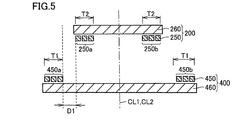
- Fig. 5 is a cross sectional view taken along the V-V arrow line in Fig. 4.
- Fig. 6 is a first plan view representing a state where the power transmission coil and the power transmission coil are positionally displaced in a vehicle width direction in the embodiment.
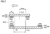
- Fig. 7 is a cross sectional view taken along the VII-VII arrow line in Fig. 6.
- Fig. 1 represents a power transfer system in the embodiment.
- Fig. 2 is a perspective view representing a configuration of a power receiving device in the embodiment.
- Fig. 3 is a perspective view representing a configuration of a power transmission
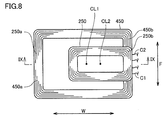
- Fig. 8 is a second plan view representing a state where the power transmission coil and the power receiving coil are positionally displaced in a vehicle width direction in the embodiment.
- Fig. 9 is a cross sectional view taken along the IX-IX arrow line in Fig. 8.
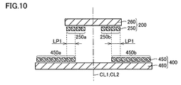
- Fig. 10 is a cross sectional view representing a state where the power transmission coil and the power receiving coil are correctly positioned in a comparative example.
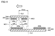
- Fig. 11 is a cross sectional view representing a state where the power transmission coil and the power receiving coil are positionally displaced in the comparative example.
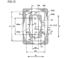
- Fig. 12 is a plan view representing a state where the power transmission coil and the power receiving coil are correctly positioned in another embodiment.
- Fig. 13 is a plan view representing a state where the power transmission coil and the power receiving coil are correctly positioned in another embodiment.
- the direction indicated by the arrow F in the drawing represents a vehicle front and back direction which includes a forward direction and a backward direction of a vehicle
- the direction indicated by the arrow W represents a vehicle width direction which includes a leftward and rightward direction orthogonal to the vehicle forward and backward direction.
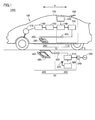
- Power Transfer System 1000 Referring to Fig. 1, a power transfer system 1000 which contactlessly transfers electric power will be described.
- Power transfer system 1000 includes a power receiving device 10 mounted to an electrically driven vehicle 100 and a power transmission device 50 installed in a facility side such as a parking lot.
- Electrically driven vehicle 100 includes power receiving device 10 and a vehicle main body 105.
- Power receiving device 10 includes a power receiving coil unit 200, and an electric device 110 provided between power receiving coil unit 200 and a battery 150 as a power storage device which stores electric power received by power receiving coil unit 200.
- Power receiving coil unit 200 has a power receiving coil 250 and a plate-like ferrite plate 260.
- a volute coil having a substantially rectangular annular form in appearance is employed as power receiving coil 250.
- Electric device 110 has a capacitor 120, a rectifier 130, a DC/DC converter 140, and the like.
- power receiving coil 250 and capacitor 220 are connected in series. However, power receiving coil 250 and capacitor 220 may be connected in parallel.
- Vehicle main body 105 includes battery 150 connected to DC/DC converter 140 of electric device 110, a power control unit 160, a motor unit 170, a communication unit 180, and the like.
- the winding number of power receiving coil 250 is appropriately set such that a distance between power receiving coil 250 and a power transmission coil 450 which will be described later, a Q value (for example, Q ⁇ 100) indicating a resonance strength between power receiving coil 250 and power transmission coil 450, and a coupling coefficient ( ⁇ ) indicating the degree of coupling become greater.
- Power receiving coil 250 is connected to rectifier 130 through capacitor 220.
- Rectifier 130 converts an alternate current supplied from power receiving coil unit 200 into a direct current and supplies the same to DC/DC converter 140.
- Power transmission device 50 includes a power transmission coil unit 400 and an electric device 300.
- Power transmission coil unit 400 has power transmission coil 450 and a plate-like ferrite plate 460.
- a volute coil having a substantially rectangular annular form in appearance is employed as power transmission coil 450.
- Electric device 300 includes a capacitor 420, a high-frequency power device 310, a power transmission ECU 320, and a communication unit 322.
- a connection with an external alternator 330 is made detachably with use of a plug 340 and the like.
- power transmission coil 450 and capacitor 420 are connected in series. However, power transmission coil 450 and capacitor 420 may be connected in parallel.
- High-frequency power device 310 converts electric power received from alternator 330 into high-frequency electric power, and supplies the converted high-frequency power to power transmission coil 450.
- Power transmission coil 450 contactlessly transmits electric power to power receiving coil 250 of power receiving coil unit 200 by means of electromagnetic induction.
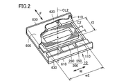
- FIG. 2 is a perspective view representing a configuration of power receiving device 10. It should be noted that power receiving device 10 is generally mounted to a bottom surface of a vehicle and arranged such that power receiving coil 250 faces power transmission coil 450 (refer to Fig. 1). However, in Fig. 2, it is illustrated upside down for ease of description.
- This power receiving device 10 has power receiving coil unit 200 which contactlessly receives electric power from power transmission device 50, and electric device 110 which is connected to power receiving coil unit 200, and these power receiving coil unit 200 and electric device 110 are accommodated in a casing 600.
- power receiving coil unit 200 and electric device 110 are integrated.
- Casing 600 includes an installation wall 610, a cover member 620, and side walls 630.
- Power receiving coil 250 employing a volute coil has a rectangular annular outer shape in which a coil line C2 is wound so as to surround a power receiving winding axis CL2 extending in the upward/downward direction of the vehicle.
- Power receiving coil 250 is wound such that a winding length (w2) in the vehicle width direction is longer than a winding length (f2) in the vehicle front and back direction.
- a position of power receiving winding axis CL2 is located at an intersection point where two diagonal lines of rectangular annular power receiving coil 250 intersect with each other.
- the winding length of power receiving coil 250 means a length measured based on an outer surface of coil line C2 located on an outermost side.
- electric device 110 is arranged in the vehicle front and back direction with respect to power receiving coil unit 200. It should be noted that, in Fig. 2, electric device 110 is divided and arranged in the front and back direction. However, electric device 110 may be arranged on a front side or a back side in the vehicle front and back direction of power receiving coil unit 200, or may be arranged in the vehicle width direction.
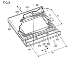
- FIG. 3 is a perspective view representing a configuration of power transmission device 50.
- This power transmission device 50 as described above, has power transmission coil unit 400 which contactlessly transmits electric power to power receiving device 10, and electric device 300 which is connected to power transmission coil unit 400, and these power transmission coil unit 400 and electric device 300 are accommodated in casing 600.
- casing 600 includes an installation wall 610, a cover member 620, and side walls 630.
- Power transmission coil 450 employing a volute coil has a rectangular annular outer shape in which a coil line C1 is wound so as to surround a power transmission winding axis CL1 extending in the upward/downward direction of the vehicle.
- Power transmission coil 450 is wound such that a winding length (w1) in the vehicle width direction becomes longer than a winding length (f1) in the vehicle front and back direction.
- a position of power transmission winding axis CL1 is located at an intersection point where two diagonal lines of rectangular annular power receiving coil 250 intersect.
- the winding length of power transmission coil 450 means a length measured based on an outer surface of coil line C1 located on an outermost side.
- electric device 300 is arranged in the vehicle front and back direction with respect to power transmission coil unit 400.
- electric device 300 is divided and arranged in the front and back direction.
- electric device 300 may be arranged on a vehicle front side or back side of power transmission coil unit 400, or may be arranged in the width direction.
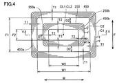
- Fig. 4 is a plan view representing a state where power transmission coil 450 and power receiving coil 250 are correctly positioned.
- Fig. 5 is a cross sectional view taken along the V-V arrow line in Fig. 4.
- Fig. 6 is a first plan view representing a state where power transmission coil 450 and power receiving coil 250 are displaced in the vehicle width direction.
- Fig. 7 is a cross sectional view taken along the VII-VII arrow line in Fig. 6.
- Fig. 8 is a second plan view representing a state where power transmission coil 450 and power receiving coil 250 are displaced in the vehicle width direction.
- Fig. 9 is a cross sectional view taken along the IX-IX arrow line in Fig. 8.
- power transmission coil 450 has a rectangular annular form in appearance
- power transmission coil 450 when power transmission coil 450 is viewed in cross section along the flat plane in vehicle width direction W including power transmission winding axis CL1, power transmission coil 450 has, across power transmission winding axis CL 1 in vehicle width direction W (horizontal direction), a first power transmission winding portion 450a located on one side (left side in Fig. 5) and a second power transmission winding portion 450b located on the other side (right side in Fig. 5).
- power receiving coil 250 also has a rectangular annular form in appearance, when power receiving coil 250 is viewed in cross section along the flat plane including power receiving winding axis CL2, power receiving coil 250 has, across power receiving winding axis CL2 in vehicle width direction W (horizontal direction), a first power receiving winding portion 250a located on one side (left side in Fig. 5) and a second power receiving winding portion 250b located on the other side (right side in Fig. 5).
- Power transmission coil 450 and power receiving coil 250 have a form in which a winding width T1 of first power transmission winding portion 450a in vehicle width direction W (horizontal direction) and a winding width T2 of first power receiving winding portion 250a in vehicle width direction W (horizontal direction) substantially matches with each other, and a form in which a winding width T1 of second power transmission winding portion 450b in vehicle width direction W (horizontal direction) and a winding width T2 of second power receiving winding portion 250b in vehicle width direction W (horizontal direction) substantially matches with each other.
- the winding width of power transmission coil 450 is substantially the same in an entire circumference
- the winding width of power receiving coil 250 is also substantially the same in an entire circumference
- the winding width of power transmission coil 450 and the winding width of power receiving coil 250 substantially match with each other.
- a space W1 in vehicle width direction W between first power transmission winding portion 450a and second power transmission winding portion 450b is set to be larger than a space F1 in vehicle front and back direction F between first power transmission winding portion 450a and second power transmission winding portion 450b
- a space W2 in vehicle width direction W between first power receiving winding portion 250a and second power receiving winding portion 250b is set to be larger than a space F2 in vehicle front and back direction F between first power receiving winding portion 250a and second power receiving winding portion 250b.
- power transmission coil 450 and power receiving coil 250 have a laterally oblong form in which a length in vehicle width direction W is longer than a length in vehicle front and back direction F.
- first power receiving winding portion 250a and second power receiving winding portion 250b are located on a side of power transmission winding axis CL1 (inner side) of first power transmission winding portion 450a and second power transmission winding portion 450b, and first power receiving winding portion 250a and second power receiving winding portion 250b are arranged so as not to overlap with first power transmission winding portion 450a and second power transmission winding portion 450b.
- power receiving coil 250 is located on an inner side of power transmission coil 450, and power receiving coil 250 has an outer shape which is smaller than the power transmission coil 450.
- first power receiving winding portion 250a and first power transmission winding portion 450a come close to each other, and, on the other hand, second power receiving winding portion 250b and second power transmission winding portion 450b are separated apart from each other.
- first power receiving winding portion 250a and second power receiving winding portion 250b are arranged with a space on an inner side of first power transmission winding portion 450a and second power transmission winding portion 450b (on a side of winding axes CL1, CL2) in a state where power transmission coil 400 and power receiving coil 200 are correctly positioned, a positional displacement performance can be improved.
- first power receiving winding portion 250a and first power transmission winding portion 450a are slightly separated apart from each other, and second power receiving winding portion 250b and second power transmission winding portion 450b are slightly separated apart from each other, magnetic circuits are formed respectively between first power receiving winding portion 250a and first power transmission winding portion 450a and between second power receiving winding portion 250b and second power transmission winding portion 450b, so that a high coupling coefficient ( ⁇ ) is maintained.
- a space (D1) between first power receiving winding portion 250a and first power transmission winding portion 450a is set to have a distance in which a favorable magnetic circuit can be formed. It similarly applies to the space between second power receiving winding portion 250b and second power transmission winding portion 450b.
- a maximum displacement amount Smax between power transmission coil 450 and power receiving coil 250 is a distance defined so that electric power of a predetermined amount or greater can be contactlessly transmitted from power transmission device 50 to power receiving device 10 at a position where power receiving winding axis CL2 is displaced with respect to power transmission winding axis CL1 in vehicle width direction W.
- maximum displacement amount Smax between power transmission winding axis CL1 and power receiving winding axis CL2 shown in Fig. 7 means a displacement amount within a range in which a predetermined amount of electric power can be transmitted contactlessly from power transmission coil unit 400 to power receiving coil unit 200.
- power transmission coil 450 and power receiving coil 250 are wound such that, in the state where power transmission winding axis CL1 and power receiving winding axis CL2 are positionally displaced, first power receiving winding portion 250a overlaps with first power transmission winding portion 450a, and second power receiving winding portion 250b does not overlap with first power transmission winding portion 450a when viewed in a plan view.
- first power receiving winding portion 250a and first power transmission winding portion 450a overlap with each other so that the winding width is matched, a positional displacement is permitted within a range in which a desired coupling coefficient ( ⁇ ) is obtained.
- power transmission coil 450 and power receiving coil 250 are wound such that, in a state where power receiving winding axis CL2 is positionally displaced with respect to power transmission winding axis CL1 toward an opposite side (vehicle width direction W, rightward direction in Fig. 9), second power receiving winding portion 250b overlaps with second power transmission winding portion 450b, and first power receiving winding portion 250a does not overlap with second power receiving winding portion 250b.
- Maximum displacement amount Smax is the same as in the description above.
- first power receiving winding portion 250a and first power transmission winding portion 450a since the widths of first power receiving winding portion 250a and first power transmission winding portion 450a substantially match with each other when power receiving coil 400 is positionally displaced to an extent causing first power receiving winding portion 250a and first power transmission winding portion 450a to face each other, a path length of a magnetic circuit MC3 formed between first power receiving winding portion 250a and first power transmission winding portion 450a can be shortened. Accordingly, a magnetic resistance of magnetic circuit MC3 can be reduced, so that a decrease in coupling coefficient ⁇ between power transmission coil 400 and power receiving coil 200 can be suppressed without coupling second power receiving winding portion 250b and second power transmission winding portion 450b.
- power transmission coil 450 and power receiving coil 250 are arranged such that distance D1 between first power receiving winding portion 250a and first power transmission winding portion 450a in Fig. 5 when viewed in a cross section along a flat plane passing through power transmission winding axis CL1 is set to be a distance causing magnetic coupling to occur in a state where power transmission coil 200 and power receiving coil 400 are correctly positioned.
- distance D2 between second power receiving winding portion 250b and first power transmission winding portion 450a in Fig. 7 and distance D2 between first power receiving winding portion 250a and second power transmission winding portion 450b in Fig. 9 are set to be a distance which does not cause occurrence of magnetic coupling.
- Figs. 10 and 11 show a structure of a comparative example.
- Fig. 10 is a cross sectional view representing a state where power transmission coil 450 and power receiving coil 250 are correctly positioned in a comparative example.
- Fig. 11 is a cross sectional view representing a state where power transmission coil 450 and power receiving coil 250 are positionally displaced in a comparative example.
- region LP1 a region in which power transmission coil 450 and power receiving coil 250 overlap with each other in a state where power transmission coil 450 and power receiving coil 250 are correctly positioned is formed (region LP1). Accordingly, magnetic circuits are respectively formed between first power receiving winding portion 250a and first power transmission winding portion 450a, and between second power receiving winding portion 250b and second power transmission winding portion 450b.
- first power receiving winding portion 250a and second power receiving winding portion 250b overlap with first power transmission winding portion 450a (region LP2, region LP3).
- magnetic circuit MC1 causes a direction of an induced current generated in first power receiving winding portion 250a and a direction of an induced current generated in second power receiving winding portion 250b are inversed, so that it has been a factor of causing lowering of coupling coefficient ( ⁇ ).
- a magnetic circuit is not formed between second power receiving winding portion 250b and first power transmission winding portion 450a as shown in Fig. 7, and a magnetic circuit is not formed between first power receiving winding portion 250a and second power transmission winding portion 450b as shown in Fig. 9, a high coupling coefficient ( ⁇ ) can be maintained without affecting the magnetic circuit formed between power transmission coil 450 and power receiving coil 250.
- ⁇ the coupling coefficient
- the space (D2) between power transmission coil 450 and power receiving coil 250 in vehicle front and back direction F and the space (D1) between power transmission coil 450 and power receiving coil 250 in vehicle width direction W are set to be equal.
- the sizes of the spaces may be different as described below.
- a positional displacement in vehicle width direction W is more likely to be large than a positional displacement in vehicle front and back direction F. Even in such a case, some extent of a positional displacement in the width direction is permissible. Therefore, an effort to park a vehicle again can be omitted.
- power transmission coil 450 and power receiving coil 250 have a laterally oblong form in which a length in vehicle width direction W is longer than a length in vehicle front and back direction F, it may be in a vertically oblong form in which a length in vehicle width direction W is shorter than a length in vehicle front and back direction F.
- a space (F3) between first power transmission winding portion 450a and second power transmission winding portion 450b, and a space (W3) between first power transmission winding portion 450a and second power transmission winding portion 450b may be set equal
- a space (F4) between first power receiving winding portion 250a and second power receiving winding portion 250b, and a space (W4) between first power receiving winding portion 250a and second power receiving winding portion 250b may be set equal.
- a square coil shape can be employed in each of power transmission coil 450 and power receiving coil 250.
- a circular coil shape can also be employed in each of power transmission coil 450 and power receiving coil 250.
- 10 power receiving device 10 power receiving device; 50 power transmission device; 100 electric motor; 105 vehicle main body; 110, 300 electric device; 120, 220, 420 capacitor; 130 rectifier; 140 converter; 150 battery; 160 power control unit; 170 motor unit; 180, 322 communication unit; 200 power receiving coil unit; 250 power receiving coil; 260, 460 ferrite plate; 310 high-frequency power device; 330 alternator; 400 power transmission coil unit; 450 power transmission coil; 600 casing; 610 installation wall; 620 cover member; 630 side wall; 1000 power transfer system.
Landscapes
- Engineering & Computer Science (AREA)
- Power Engineering (AREA)
- Transportation (AREA)
- Mechanical Engineering (AREA)
- Computer Networks & Wireless Communication (AREA)
- Electric Propulsion And Braking For Vehicles (AREA)
- Current-Collector Devices For Electrically Propelled Vehicles (AREA)
- Charge And Discharge Circuits For Batteries Or The Like (AREA)
Priority Applications (3)
| Application Number | Priority Date | Filing Date | Title |
|---|---|---|---|
| US15/518,329 US10399460B2 (en) | 2014-10-28 | 2015-08-12 | Power transfer system, power transmission device, and power receiving device |
| EP15756492.3A EP3213330B1 (en) | 2014-10-28 | 2015-08-12 | Power transfer system, power transmission device, and power receiving device |
| CN201580058478.2A CN107078563B (zh) | 2014-10-28 | 2015-08-12 | 电力传输系统、送电装置、以及受电装置 |
Applications Claiming Priority (2)
| Application Number | Priority Date | Filing Date | Title |
|---|---|---|---|
| JP2014-219425 | 2014-10-28 | ||
| JP2014219425A JP6550718B2 (ja) | 2014-10-28 | 2014-10-28 | 電力伝送システム |
Publications (1)
| Publication Number | Publication Date |
|---|---|
| WO2016067500A1 true WO2016067500A1 (en) | 2016-05-06 |
Family
ID=54011844
Family Applications (1)
| Application Number | Title | Priority Date | Filing Date |
|---|---|---|---|
| PCT/JP2015/004036 Ceased WO2016067500A1 (en) | 2014-10-28 | 2015-08-12 | Power transfer system, power transmission device, and power receiving device |
Country Status (5)
| Country | Link |
|---|---|
| US (1) | US10399460B2 (enExample) |
| EP (1) | EP3213330B1 (enExample) |
| JP (1) | JP6550718B2 (enExample) |
| CN (1) | CN107078563B (enExample) |
| WO (1) | WO2016067500A1 (enExample) |
Cited By (1)
| Publication number | Priority date | Publication date | Assignee | Title |
|---|---|---|---|---|
| FR3165821A1 (fr) | 2024-09-04 | 2026-03-06 | Upandcharge | dispositif de recharge par induction des batteries électriques rechargeables d’un véhicule électrique |
Families Citing this family (4)
| Publication number | Priority date | Publication date | Assignee | Title |
|---|---|---|---|---|
| DE102016205352A1 (de) * | 2016-03-31 | 2017-10-05 | Bayerische Motoren Werke Aktiengesellschaft | Primärspuleneinheit |
| JP6485440B2 (ja) * | 2016-12-21 | 2019-03-20 | トヨタ自動車株式会社 | 車両および非接触送受電システム |
| JP6897371B2 (ja) * | 2017-07-03 | 2021-06-30 | トヨタ自動車株式会社 | 車両および電力伝送システム |
| JP7332133B2 (ja) * | 2019-03-29 | 2023-08-23 | ラピスセミコンダクタ株式会社 | アンテナシステム |
Citations (9)
| Publication number | Priority date | Publication date | Assignee | Title |
|---|---|---|---|---|
| US20120112552A1 (en) * | 2010-09-26 | 2012-05-10 | Access Business Group International Llc | Selectively controllable electromagnetic shielding |
| JP2013110822A (ja) | 2011-11-18 | 2013-06-06 | Toyota Motor Corp | 電力伝送システム、車両、および給電設備 |
| JP2013126327A (ja) | 2011-12-15 | 2013-06-24 | Toyota Motor Corp | 受電装置およびそれを備える車両、送電装置、ならびに電力伝送システム |
| JP2013146148A (ja) | 2012-01-16 | 2013-07-25 | Toyota Motor Corp | 車両 |
| JP2013146154A (ja) | 2012-01-16 | 2013-07-25 | Toyota Motor Corp | 受電装置、送電装置および電力伝送システム |
| JP2013154815A (ja) | 2012-01-31 | 2013-08-15 | Toyota Motor Corp | 車両および電力伝送システム |
| US20140015341A1 (en) * | 2011-03-18 | 2014-01-16 | Yazaki Corporation | Power supplying system |
| JP2014011852A (ja) | 2012-06-28 | 2014-01-20 | Panasonic Corp | 携帯端末 |
| JP2014039462A (ja) | 2008-07-08 | 2014-02-27 | Qualcomm Incorporated | 規制的制約下における無線高電力伝送 |
Family Cites Families (11)
| Publication number | Priority date | Publication date | Assignee | Title |
|---|---|---|---|---|
| US7825543B2 (en) | 2005-07-12 | 2010-11-02 | Massachusetts Institute Of Technology | Wireless energy transfer |
| WO2007008646A2 (en) | 2005-07-12 | 2007-01-18 | Massachusetts Institute Of Technology | Wireless non-radiative energy transfer |
| CA2682284C (en) | 2007-03-27 | 2016-08-16 | Massachusetts Institute Of Technology | Wireless energy transfer |
| US20100277121A1 (en) * | 2008-09-27 | 2010-11-04 | Hall Katherine L | Wireless energy transfer between a source and a vehicle |
| JP5556149B2 (ja) * | 2009-11-30 | 2014-07-23 | 株式会社オートネットワーク技術研究所 | 無線給電システム及び無線給電システムの設計方法 |
| JP2012138976A (ja) * | 2010-12-24 | 2012-07-19 | Equos Research Co Ltd | 電力伝送システム |
| JP5838562B2 (ja) * | 2011-02-17 | 2016-01-06 | 富士通株式会社 | ワイヤレス送電装置及びワイヤレス送電システム |
| JP5773693B2 (ja) * | 2011-03-18 | 2015-09-02 | 矢崎総業株式会社 | 給電システム |
| JP2012200031A (ja) * | 2011-03-18 | 2012-10-18 | Yazaki Corp | 給電システム |
| JP2013125620A (ja) * | 2011-12-14 | 2013-06-24 | Panasonic Corp | 誘導加熱装置 |
| US9178361B2 (en) * | 2012-09-27 | 2015-11-03 | ConvenientPower, Ltd. | Methods and systems for detecting foreign objects in a wireless charging system |
-
2014
- 2014-10-28 JP JP2014219425A patent/JP6550718B2/ja active Active
-
2015
- 2015-08-12 US US15/518,329 patent/US10399460B2/en active Active
- 2015-08-12 WO PCT/JP2015/004036 patent/WO2016067500A1/en not_active Ceased
- 2015-08-12 CN CN201580058478.2A patent/CN107078563B/zh active Active
- 2015-08-12 EP EP15756492.3A patent/EP3213330B1/en active Active
Patent Citations (9)
| Publication number | Priority date | Publication date | Assignee | Title |
|---|---|---|---|---|
| JP2014039462A (ja) | 2008-07-08 | 2014-02-27 | Qualcomm Incorporated | 規制的制約下における無線高電力伝送 |
| US20120112552A1 (en) * | 2010-09-26 | 2012-05-10 | Access Business Group International Llc | Selectively controllable electromagnetic shielding |
| US20140015341A1 (en) * | 2011-03-18 | 2014-01-16 | Yazaki Corporation | Power supplying system |
| JP2013110822A (ja) | 2011-11-18 | 2013-06-06 | Toyota Motor Corp | 電力伝送システム、車両、および給電設備 |
| JP2013126327A (ja) | 2011-12-15 | 2013-06-24 | Toyota Motor Corp | 受電装置およびそれを備える車両、送電装置、ならびに電力伝送システム |
| JP2013146148A (ja) | 2012-01-16 | 2013-07-25 | Toyota Motor Corp | 車両 |
| JP2013146154A (ja) | 2012-01-16 | 2013-07-25 | Toyota Motor Corp | 受電装置、送電装置および電力伝送システム |
| JP2013154815A (ja) | 2012-01-31 | 2013-08-15 | Toyota Motor Corp | 車両および電力伝送システム |
| JP2014011852A (ja) | 2012-06-28 | 2014-01-20 | Panasonic Corp | 携帯端末 |
Cited By (2)
| Publication number | Priority date | Publication date | Assignee | Title |
|---|---|---|---|---|
| FR3165821A1 (fr) | 2024-09-04 | 2026-03-06 | Upandcharge | dispositif de recharge par induction des batteries électriques rechargeables d’un véhicule électrique |
| WO2026053105A1 (fr) | 2024-09-04 | 2026-03-12 | Upandcharge | Dispositif de recharge par induction des batteries électriques rechargeables d'un véhicule électrique |
Also Published As
| Publication number | Publication date |
|---|---|
| EP3213330B1 (en) | 2021-04-07 |
| US20170326993A1 (en) | 2017-11-16 |
| CN107078563A (zh) | 2017-08-18 |
| JP6550718B2 (ja) | 2019-07-31 |
| US10399460B2 (en) | 2019-09-03 |
| JP2016086592A (ja) | 2016-05-19 |
| EP3213330A1 (en) | 2017-09-06 |
| CN107078563B (zh) | 2020-02-07 |
Similar Documents
| Publication | Publication Date | Title |
|---|---|---|
| US10250071B2 (en) | Wireless power supply coil | |
| EP3213330B1 (en) | Power transfer system, power transmission device, and power receiving device | |
| JP6131915B2 (ja) | 送電装置および受電装置 | |
| US9876364B2 (en) | Power receiving device, vehicle, and power transmission device | |
| US20150091518A1 (en) | Charging configuration for the inductive wireless emission of energy | |
| EP3282459B1 (en) | Ground-side coil unit | |
| JP6217518B2 (ja) | ワイヤレス給電システムおよびワイヤレス電力伝送システム | |
| US20140306655A1 (en) | Contactless battery charger | |
| WO2015159466A1 (en) | Vehicle and contactless power transfer system | |
| CN106575886A (zh) | 受电线圈装置以及非接触供电系统 | |
| JP6331902B2 (ja) | 送電装置 | |
| US10673276B2 (en) | Coil device, wireless power transfer system, and auxiliary magnetic member | |
| JP2016129164A (ja) | 受電装置および送電装置 | |
| US20190237248A1 (en) | Coil Unit for Inductively Charging a Vehicle | |
| CN105765826A (zh) | 受电装置和送电装置 | |
| JP6217435B2 (ja) | 受電装置 | |
| CN104685796B (zh) | 通信系统 | |
| JP6894819B2 (ja) | 非接触給電装置および電気回路モジュール | |
| EP3654493A1 (en) | Contactless power transfer system having two parallel conductors | |
| WO2015122344A1 (ja) | コイルユニット及びそれを有する給電システム | |
| JP6587895B2 (ja) | 非接触給電システム | |
| JP2018081960A (ja) | コイルユニット、及び、非接触給電システム | |
| WO2014076953A1 (ja) | 非接触で電力を伝送する装置のコイルに使用するコア | |
| WO2015083537A1 (ja) | リッツ線 | |
| JP2016073018A (ja) | 送電装置 |
Legal Events
| Date | Code | Title | Description |
|---|---|---|---|
| 121 | Ep: the epo has been informed by wipo that ep was designated in this application |
Ref document number: 15756492 Country of ref document: EP Kind code of ref document: A1 |
|
| WWE | Wipo information: entry into national phase |
Ref document number: 15518329 Country of ref document: US |
|
| NENP | Non-entry into the national phase |
Ref country code: DE |
|
| REEP | Request for entry into the european phase |
Ref document number: 2015756492 Country of ref document: EP |