WO2016060165A1 - 透明部材、透明部材の製造方法および透明部材の表面の汚れ具合の評価方法 - Google Patents
透明部材、透明部材の製造方法および透明部材の表面の汚れ具合の評価方法 Download PDFInfo
- Publication number
- WO2016060165A1 WO2016060165A1 PCT/JP2015/079059 JP2015079059W WO2016060165A1 WO 2016060165 A1 WO2016060165 A1 WO 2016060165A1 JP 2015079059 W JP2015079059 W JP 2015079059W WO 2016060165 A1 WO2016060165 A1 WO 2016060165A1
- Authority
- WO
- WIPO (PCT)
- Prior art keywords
- transparent member
- hydrophilic coating
- coating film
- luminance value
- water
- Prior art date
Links
Images


Classifications
-
- C—CHEMISTRY; METALLURGY
- C03—GLASS; MINERAL OR SLAG WOOL
- C03C—CHEMICAL COMPOSITION OF GLASSES, GLAZES OR VITREOUS ENAMELS; SURFACE TREATMENT OF GLASS; SURFACE TREATMENT OF FIBRES OR FILAMENTS MADE FROM GLASS, MINERALS OR SLAGS; JOINING GLASS TO GLASS OR OTHER MATERIALS
- C03C15/00—Surface treatment of glass, not in the form of fibres or filaments, by etching
-
- C—CHEMISTRY; METALLURGY
- C03—GLASS; MINERAL OR SLAG WOOL
- C03C—CHEMICAL COMPOSITION OF GLASSES, GLAZES OR VITREOUS ENAMELS; SURFACE TREATMENT OF GLASS; SURFACE TREATMENT OF FIBRES OR FILAMENTS MADE FROM GLASS, MINERALS OR SLAGS; JOINING GLASS TO GLASS OR OTHER MATERIALS
- C03C17/00—Surface treatment of glass, not in the form of fibres or filaments, by coating
- C03C17/22—Surface treatment of glass, not in the form of fibres or filaments, by coating with other inorganic material
- C03C17/23—Oxides
-
- C—CHEMISTRY; METALLURGY
- C03—GLASS; MINERAL OR SLAG WOOL
- C03C—CHEMICAL COMPOSITION OF GLASSES, GLAZES OR VITREOUS ENAMELS; SURFACE TREATMENT OF GLASS; SURFACE TREATMENT OF FIBRES OR FILAMENTS MADE FROM GLASS, MINERALS OR SLAGS; JOINING GLASS TO GLASS OR OTHER MATERIALS
- C03C17/00—Surface treatment of glass, not in the form of fibres or filaments, by coating
- C03C17/28—Surface treatment of glass, not in the form of fibres or filaments, by coating with organic material
- C03C17/32—Surface treatment of glass, not in the form of fibres or filaments, by coating with organic material with synthetic or natural resins
-
- C—CHEMISTRY; METALLURGY
- C03—GLASS; MINERAL OR SLAG WOOL
- C03C—CHEMICAL COMPOSITION OF GLASSES, GLAZES OR VITREOUS ENAMELS; SURFACE TREATMENT OF GLASS; SURFACE TREATMENT OF FIBRES OR FILAMENTS MADE FROM GLASS, MINERALS OR SLAGS; JOINING GLASS TO GLASS OR OTHER MATERIALS
- C03C19/00—Surface treatment of glass, not in the form of fibres or filaments, by mechanical means
-
- G—PHYSICS
- G01—MEASURING; TESTING
- G01B—MEASURING LENGTH, THICKNESS OR SIMILAR LINEAR DIMENSIONS; MEASURING ANGLES; MEASURING AREAS; MEASURING IRREGULARITIES OF SURFACES OR CONTOURS
- G01B11/00—Measuring arrangements characterised by the use of optical techniques
- G01B11/30—Measuring arrangements characterised by the use of optical techniques for measuring roughness or irregularity of surfaces
-
- G—PHYSICS
- G01—MEASURING; TESTING
- G01N—INVESTIGATING OR ANALYSING MATERIALS BY DETERMINING THEIR CHEMICAL OR PHYSICAL PROPERTIES
- G01N21/00—Investigating or analysing materials by the use of optical means, i.e. using sub-millimetre waves, infrared, visible or ultraviolet light
- G01N21/84—Systems specially adapted for particular applications
- G01N21/88—Investigating the presence of flaws or contamination
- G01N21/95—Investigating the presence of flaws or contamination characterised by the material or shape of the object to be examined
- G01N21/958—Inspecting transparent materials or objects, e.g. windscreens
Definitions
- the present invention relates to a transparent member, a method for producing the transparent member, and an evaluation method for evaluating the degree of contamination on the surface of the transparent member.
- Transparent members such as glass plates are used in various applications such as building windows, vehicle windshields, and solar cell cover glasses.
- dirt in the atmosphere adheres to and accumulates on a transparent member used outdoors, the appearance and translucency deteriorate. A decrease in translucency leads to a decrease in visibility and power generation efficiency.
- a method for imparting antifouling properties for example, a method has been proposed in which a surface is provided with a water-repellent or hydrophilic (oil-repellent) coating to prevent adhesion of dirt (for example, Patent Document 1).
- the surface of the transparent member is contaminated by spraying a contamination promoting liquid (an aqueous dispersion of Kanto Loam, etc.), and then the haze value of the transparent member or the gloss of the surface is measured.
- a contamination promoting liquid an aqueous dispersion of Kanto Loam, etc.
- the evaluation based on the haze value and the gloss value cannot be distinguished from, for example, a case where the surface is heavily soiled and a case where the surface is entirely thinly soiled. Therefore, even transparent members that exhibit good antifouling properties with such an index may actually appear dirty.
- the surface is imaged by an imaging means installed in a direction orthogonal to the irradiation direction to obtain image data of the surface, and image processing is performed on two regions having a size of 15 mm ⁇ 15 mm that are randomly extracted from the image data.
- a luminance value distribution histogram is created with the luminance value of 256 gradations on the horizontal axis and the ratio of the number of pixels on the vertical axis.
- the width of the bin in the luminance value distribution histogram is 1.
- the ratio of the number of pixels the transparent member in luminance value distribution histogram to x 0 for the luminance value becomes maximum.
- the following contamination promoting liquid is sprayed on the surface of the transparent member for 5 seconds using the following spraying device and dried at 60 ° C. for 1 hour, and then tap water is applied to the surface using the spraying device.
- the process of spraying for 180 seconds and drying at 60 ° C. for 1 hour is performed as 3 cycles for 3 cycles.
- the surface is irradiated with light having an illuminance of 20000 lux in the same procedure as above, and the surface is imaged to obtain image data of the surface, which is randomly extracted from the image data.
- 2 regions having a size of 15 mm ⁇ 15 mm are analyzed by image processing software, and a luminance value distribution histogram is created with luminance values of 256 gradations on the horizontal axis and the number of pixels on the vertical axis. For the luminance value distribution histogram obtained after the third cycle, let the luminance value corresponding to the ratio of the number of pixels be x i .
- Contamination promoting liquid 11 kinds of test powder 1 (Kanto loam, median diameter 1.6 to 2.3 ⁇ m) defined in JIS Z 8901 (2006) are dispersed in water at a concentration of 0.1% by mass. Dispersion.
- Spraying device A two-fluid nozzle spray gun installed at a position 600 mm away from the surface with a sprayed droplet size of 10 ⁇ m and a spray amount of 20 g / min.
- a root mean square value ⁇ is calculated from the x 0 and x i by the following equation (1).
- i represents the ratio of the number of pixels, and is an integer from 0 to 100.
- n indicates the maximum value of the ratio of the number of pixels, and is 100.
- the surface having the root mean square value ⁇ of 40 or less is a surface having irregularities, the protrusion density on the surface is 0.1 to 100 ⁇ m ⁇ 2 , and the arithmetic average surface roughness (Ra ) Is 2 to 60 nm and the water contact angle is 0 to 10 °, the transparent member according to [1].
- the transparent member according to [1] or [2], wherein the surface having a root mean square value ⁇ of 40 or less is a surface having a hydrophilic coating film.
- a transparent member having a surface with irregularities wherein the surface having irregularities has an arithmetic average surface roughness (Ra) of 8.5 to 30 nm and a root mean square roughness (Rq) of 11 to 30 nm. .
- Ra arithmetic average surface roughness
- Rq root mean square roughness
- a method for producing a transparent member wherein a glass plate having a hydrophilic coating film on the surface thereof is subjected to the following wet blast treatment on the surface of the hydrophilic coating film.
- Wet blasting A liquid in which particles are dispersed is sprayed on the surface of the hydrophilic coating film, whereby an arithmetic average surface roughness (Ra) of 8.5 to 30 nm and a root mean square roughness (Ra) are applied to the surface of the hydrophilic coating film ( Treatment for forming irregularities with Rq) of 11 to 30 nm.
- a method for producing a transparent member wherein a hydrophilic coating film is formed by applying a hydrophilic coating agent to the surface on which the irregularities are formed, The wet etching treatment of the surface having the water repellent pattern film is such that the arithmetic average surface roughness (Ra) of the surface on which the hydrophilic coating film is formed is 8.5 to 30 nm and the root mean square roughness (Rq) is 11 A method for producing a transparent member, which is performed so as to have a thickness of 30 nm.
- the transparent member of the present invention is excellent in antifouling property. According to the method for producing a transparent member of the present invention, a transparent member having excellent antifouling properties can be obtained. If the degree of dirt on the surface of the transparent member is evaluated by the evaluation method of the present invention, an evaluation result showing good correspondence with the visual evaluation can be obtained.
- FIG. 6 It is the schematic explaining the spraying apparatus and the spraying method using the same. It is a schematic block diagram of the apparatus used for the irradiation of the light to the surface of a transparent member, the imaging of a surface, and image analysis. It is a figure which shows arrangement
- FIG. 14 is a graph in which processing time of wet blast processing in Examples 7 to 13 is plotted on the horizontal axis and measured values of Ra and Rq (unit: nm) are plotted on the vertical axis. It is the photograph which image
- Transparent in the transparent member means that 80% or more of light in the wavelength region of 400 to 1100 nm is transmitted on average.
- Protrusion density means the number of protrusions per unit area (unit: pieces ⁇ ⁇ m ⁇ 2 ) when a protrusion having a height of 2 nm or more between adjacent protrusions and recesses is defined as a protrusion.
- Arithmetic mean surface roughness (Ra)” and “Root mean square roughness (Rq)” are values measured by an atomic force microscope (AFM), respectively.
- Water contact angle is a value measured using a contact angle meter and setting the size of a droplet (water droplet) to 20 ⁇ L.
- a liquid containing a dirt substance (hereinafter, also referred to as “fouling promoting liquid”) is sprayed on the surface of the transparent member to attach the dirt, washed with water, Light is applied to the surface with the dirt attached, the surface is imaged by an imaging means to obtain image data, a brightness value distribution is created based on the image data, In the luminance value distribution, the degree of contamination of the surface is evaluated from a ratio between an integrated value of luminance values equal to or higher than a preset threshold value and an integrated value of the entire luminance value distribution.
- the irradiated light hits and scatters the dirt adhering to the surface after spraying the contamination promoting liquid and washing with water. Therefore, in an image obtained by imaging the surface under light irradiation, dirt attached to the surface is observed as white bright spots. That is, it can be determined that the number of bright spots is the number of attached dirt. Further, the larger the adhered dirt, the stronger the scattered light and the higher the brightness value of the bright spot. Therefore, it can be determined that the larger the luminance value on the image is, the more conspicuous dirt is.
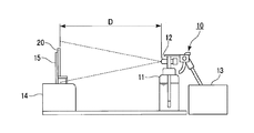
- FIG. 1 is a schematic diagram illustrating a spraying apparatus and a spraying method using the spraying apparatus.
- FIG. 2 is a schematic configuration diagram of an apparatus used for imaging and image analysis of the surface of the transparent member.
- the spraying device 10 includes a tank 11 that stores a contamination promoting liquid or tap water, a two-fluid nozzle 12 attached to the tank 11, and a compressor 13 that supplies air to the two-fluid nozzle 12.
- the transparent member 20 on which the contamination promoting liquid and tap water are sprayed is installed on the height adjusting table 14 by the fixing table 15 so as to be perpendicular to the horizontal plane.
- the distance between the surface of the transparent member 20 and the tip of the two-fluid nozzle 12 is 600 mm, the center in the spray direction of the contamination promoting liquid or tap water (the position of the tip of the two-fluid nozzle 12) and the center of the transparent member 20 Are consistent.
- An apparatus used for light irradiation on the surface of the transparent member, imaging of the surface, and image analysis is installed in a dark room, and includes a visual inspection light 31, a digital camera (imaging means) 32, a digital camera 32, and a transparent.
- the visual inspection light 31 is installed in the direction of the fixture 33 so as to irradiate light parallel to the horizontal plane.
- the digital camera 32 is fixed to the fixture 33 with the lens facing downward in the vertical direction (transparent member 20 side) with respect to the horizontal plane. Further, it is connected to a computer 34 so that photographed photograph data can be input to the computer 34.
- the irradiation direction of the light from the visual inspection light 31 is orthogonal to the direction in which the lens of the digital camera 32 is directed.
- the visual inspection light 31 is preferably capable of irradiating light having an illuminance of about 15000 to 25000 lux.
- An example of the digital camera 32 includes a camera having 15 million effective pixels or more and a sensor size APS-C. During the evaluation, the setting of the digital camera 32 is not changed.
- the fixture 33 is a rod-like instrument installed perpendicular to the horizontal plane, and includes a camera fixing portion at the upper portion and a transparent member fixing portion at a lower side thereof.
- the height of the transparent member fixing portion is substantially the same as the height of the visual inspection light 31.
- the transparent member fixing portion is configured to sandwich the transparent member 20 from the front surface side and the back surface side, and to adjust the angle of the surface of the transparent member 20 with respect to the irradiation direction of the light from the visual inspection light 31.
- the evaluation method using the apparatus shown in FIGS. 1 and 2 can be performed, for example, by the following procedure.
- Two spraying apparatuses 10 are prepared, and the contamination promoting liquid is stored in the tank 11 of one spraying apparatus 10, and tap water is stored in the tank 11 of the other spraying apparatus 10.
- the transparent member 20 is installed on the fixed table 15, and the fixed table 15 is installed on the table 14. Thereby, the transparent member 20 is installed perpendicularly
- the spraying device 10 containing the contamination promoting liquid is installed at a position facing the surface of the transparent member 20, and the contamination promoting liquid is sprayed from the position onto the surface of the transparent member 20 and dried.
- the spraying device 10 containing the contamination promoting liquid is replaced with the spraying device 10 containing tap water, and the tap water is sprayed on the surface of the transparent member 20 and dried.
- the above-described spraying and drying of the pollution promoting liquid and the spraying and drying of tap water are defined as one cycle, and two or more cycles are performed as necessary.
- the distance D between the surface of the transparent member 20 and the tip of the two-fluid nozzle 12 of the spraying device 10 is appropriately set so that the contamination promoting liquid and tap water are sprayed on the entire surface of the transparent member 20.
- the number of cycles is preferably 1 to 5 times, and particularly preferably 3 times in terms of efficiency.
- a luminance value distribution histogram is created in the following procedure before and after the above cycle.
- the transparent member 20 is directed to the fixture 33 in the dark room, the surface 20a is directed upward (to the digital camera 32 side), and the irradiation direction D1 of the light from the visual inspection light 31 and the surface 20a of the transparent member 20 are formed.
- the angle ⁇ 1 is fixed to a desired value.
- the angle ⁇ 1 is preferably ⁇ 5 to 30 °.
- FIG. 3 shows the arrangement of the transparent member 20 when the angle ⁇ 1 is a positive value.
- the light irradiation direction D1 is orthogonal to the direction D2 in which the lens of the digital camera 32 is directed.
- the horizontal axis represents the luminance value of 2 m gradation and the vertical axis represents A luminance value distribution histogram taking the ratio of the number of pixels is created.
- m is 6 to 20, and preferably 8 to 16. As m is larger, more detailed luminance value information can be obtained. It is preferable that m is 8 (256 gradations) or more in that the difference between the dirt and the base material is sufficiently discriminated.
- the evaluation method of the present invention is not limited to the above procedure.
- the imaging means is not limited to a digital camera, and may be a film camera or the like. Image processing software other than ImageJ may be used.
- transparent member (A) has a root mean square value (RMS value) ⁇ determined by the following method (I) of 40 or less.
- the following contamination promoting liquid is sprayed on the surface of the transparent member for 5 seconds using the following spraying device and dried at 60 ° C. for 1 hour, and then tap water is applied to the surface using the spraying device.
- the process of spraying for 180 seconds and drying at 60 ° C. for 1 hour is performed as 3 cycles for 3 cycles.
- the surface is irradiated with light having an illuminance of 20000 lux in the same procedure as above, and the surface is imaged to obtain image data of the surface, which is randomly extracted from the image data.
- Contamination promoting liquid 11 kinds of test powder 1 (Kanto loam, median diameter 1.6 to 2.3 ⁇ m) defined in JIS Z 8901 (2006) are dispersed in water at a concentration of 0.1% by mass. Dispersion.
- Spraying device A two-fluid nozzle spray gun installed at a position 600 mm away from the surface with a sprayed droplet size of 10 ⁇ m and a spray amount of 20 g / min.
- the RMS value ⁇ is calculated from the obtained x 0 and x i by the following equation (1).
- i in Formula (1) shows the ratio of the number of pixels, and takes an integer from 0 to 100 in increments of 1.
- n indicates the maximum value of the ratio of the number of pixels, and is 100.
- Method (I) can be carried out using the apparatus shown in FIGS.
- the smaller the RMS value ⁇ obtained by the above-mentioned equation (1) the closer the state of contamination is to the state before spraying the contamination promoting liquid. That is, the dirt is difficult to adhere or the attached dirt is easily removed by washing with water, rain, or the like. Therefore, the transparent member (A) is less likely to accumulate large conspicuous dirt on the surface outdoors, and the appearance and translucency are less likely to deteriorate even when placed outdoors for a long period of time. Also, the cleaning cost for removing dirt is low.
- the RMS value ⁇ can be adjusted by the hydrophilicity of the surface of the transparent member, the surface shape, and the like. For example, the RMS value ⁇ tends to be smaller when the surface of the transparent member is hydrophilic than when the surface of the transparent member is hydrophobic. When unevenness is formed on the surface of the transparent member, the RMS value ⁇ tends to be smaller than when no unevenness is formed. In the case where unevenness is formed on the surface, the RMS value ⁇ can be adjusted by the size of the unevenness, the interval between the plurality of protrusions or recesses, the shape of the unevenness, and the like.
- the transparent member (A) has a surface protrusion density of 0.1 to 100 ⁇ m ⁇ 2 , an arithmetic average surface roughness (Ra) of 2 to 60 nm, and a water contact angle of 0 to 10 °. More preferably, the protrusion density is 0.2 to 100 ⁇ ⁇ m ⁇ 2 , the arithmetic average surface roughness (Ra) is 2 to 50 nm, the water contact angle is 0 to 8 °, and the protrusion density is 0. in .4 ⁇ 100 ⁇ [mu] m -2, arithmetic average surface roughness (Ra) in the 2 ⁇ 45 nm, and further preferably water contact angle of 0 ⁇ 5 °. If the surface protrusion density, arithmetic average surface roughness, and water contact angle are within the above ranges, the RMS value ⁇ tends to be 40 or less.
- the transparent member (A) has a base material and a hydrophilic coating film provided on the base material, and there are irregularities on the surface of the portion where the hydrophilic coating film is provided.
- a transparent substrate hereinafter, also referred to as “transparent substrate (A1)” having an RMS value ⁇ of 40 or less is preferable. Examples of the substrate and the hydrophilic coating film include those shown in the first embodiment described later.
- a glass plate is preferable as the substrate.
- a glass plate having irregularities formed on the surface examples thereof include a method of forming a hydrophilic coating film thereon, and a method of forming by wet blasting, as shown in the method for producing a transparent member of the second aspect described later.
- a method of forming by wet blasting is preferable. If the unevenness is formed by wet blasting, the antifouling property is more excellent.
- the wet blast treatment is preferably performed so that the arithmetic average surface roughness (Ra) of the surface to be processed is 8.5 to 30 nm and the root mean square roughness (Rq) is 11 to 30 nm. More preferably, the arithmetic average surface roughness (Ra) of the surface is 8.5 to 25 nm and the root mean square roughness (Rq) is 11 to 25 nm.
- FIG. 4 is a cross-sectional view schematically showing the first embodiment of the transparent member (A).
- the transparent member 1 according to the first embodiment includes a base material 3 having an uneven surface and a hydrophilic coating film 5 formed on the surface of the base material 3.
- the RMS value ⁇ obtained by the method (I) of the transparent member 1 is 40 or less.
- the substrate 3 is not particularly limited as long as it is transparent. “Transparent” here is synonymous with “transparent” in the transparent member.
- Examples of the form of the substrate 3 include a plate and a film. In the case of a plate shape, it is not limited to a flat plate shape as illustrated, and the entire surface or a part thereof may have a curvature.
- Examples of the material of the base material 3 include glass and resin. Examples of the glass include soda lime glass, borosilicate glass, aluminosilicate glass, and alkali-free glass. Examples of the resin include polyethylene terephthalate, polycarbonate, triacetyl cellulose, polymethyl methacrylate, and the like.
- a glass plate is preferable in terms of excellent ultraviolet resistance (UV) resistance and heat resistance.
- the glass plate may be a glass plate having a curved surface as well as a flat glass plate.
- the glass plate may be a tempered glass plate such as a chemically tempered glass plate or an air-cooled tempered glass plate.
- Concavities and convexities are formed on the surface of the substrate 3 (surface on the hydrophilic coating film 5 side).
- the surface shape of the substrate 3 include a shape in which a plurality of convex portions and / or concave portions are randomly distributed, a shape in which a plurality of convex portions and / or concave portions are regularly arranged, and the like.
- the shape and size of the plurality of convex portions and / or concave portions may be the same or different.
- protrusion scattered, etc. are mentioned.
- the elongate groove channel extended on the surface of the base material 3, the hole scattered, etc.
- the shape of the ridge or groove include a straight line, a curved line, a bent shape, and the like.
- a plurality of ridges or grooves may exist in parallel to form a stripe shape.
- the cross-sectional shape of the ridges or grooves in the direction perpendicular to the longitudinal direction include polygons such as triangles (V-shaped), semicircles, and the like.
- Examples of the shape of the protrusion include a polygonal pyramid shape such as a triangular pyramid shape, a quadrangular pyramid shape, and a hexagonal pyramid shape, a conical shape, a hemispherical shape, a polyhedral shape, and other various indefinite shapes.
- Protrusion density of the surface of the substrate 3 is preferably 0.1 to 100 ⁇ [mu] m -2, more preferably 0.2 to 100 ⁇ [mu] m -2, more preferably 0.4 to 100 ⁇ [mu] m -2 . If the protrusion density on the surface of the substrate 3 is within the above range, the surface Ra of the hydrophilic coating film formed on the surface, that is, the protrusion density on the surface of the transparent member 1 tends to be within the range described later.
- the arithmetic average surface roughness (Ra) of the surface of the substrate 3 is preferably 2 to 60 nm, more preferably 2 to 50 nm, still more preferably 2 to 45 nm, particularly preferably 8.5 to 30 nm, and 8.5 to 25 nm. Is most preferred. If the Ra of the surface of the substrate 3 is within the above range, the Ra of the surface of the hydrophilic coating film formed on the surface, that is, the Ra of the surface of the transparent member 1 is likely to be within the range described later.
- the thickness of the substrate 3 is not particularly limited, but is preferably 0.3 to 15.0 mm, and more preferably 0.5 to 12.0 mm. If the thickness of the base material 3 is not less than the lower limit of the above range, the mechanical strength of the base material is excellent. If the thickness of the base material 3 is not more than the upper limit of the above range, the transmittance is excellent.
- the hydrophilic coating film 5 is provided to increase the hydrophilicity of the surface. Since the surface of the transparent member 1 is hydrophilic, hydrophobic dirt is difficult to adhere. Moreover, the dirt adhering to the surface is easily removed by rain, water washing or the like.
- Examples of the hydrophilic coating film 5 include a film formed from a hydrophilic coating agent.
- Examples of the material of the hydrophilic film to be formed include hydrophilic polymers and metal oxides such as silica and titania.
- Examples of the hydrophilic coating agent include solutions and dispersions of polymers having many hydrophilic groups, silica particle dispersions, titania particle dispersions, alkoxysilane partial hydrolysates solutions and dispersions, and the like.
- Commercially available hydrophilic coating agents include LAMBIC series hydrophilic coating agents manufactured by Osaka Organic Chemical Industry Co., Ltd., and ST-K series hydrophilic coating agents that are photocatalytic titanium oxide coating agents manufactured by Ishihara Sangyo Co., Ltd. .
- a hydrophilic polymer film is formed from the LAMBIC series hydrophilic coating agent, and a hydrophilic titanium oxide film is formed from the ST-K series hydrophilic coating agent.
- the thickness of the hydrophilic coating film 5 is preferably 0.01 to 1.00 ⁇ m, more preferably 0.02 to 0.20 ⁇ m. If the thickness of the hydrophilic coating film 5 is not less than the lower limit of the above range, the hydrophilicity is excellent. If the thickness of the base material 3 is not more than the upper limit of the above range, the visibility is excellent.
- the hydrophilic coating film 5 is formed on the surface of the base material 3 having irregularities formed on the surface, the surface of the hydrophilic coating film 5, that is, the surface of the transparent member 1 is the same as the surface of the base material 3. , There are irregularities.
- the protrusion density on the surface of the hydrophilic coating film 5 (the protrusion density on the surface of the transparent member 1) is preferably 0.1 to 100 pieces / ⁇ m ⁇ 2 , more preferably 0.2 to 100 pieces / ⁇ m ⁇ 2 , and 0 More preferably, 4 to 100 ⁇ ⁇ m ⁇ 2 .
- the RMS value ⁇ obtained by the method (I) tends to be 40 or less.
- the protrusion density on the surface of the transparent member 1 can be adjusted by the protrusion density on the surface of the substrate 3.
- the arithmetic average surface roughness (Ra) of the surface of the transparent member 1 is preferably 2 to 60 nm, more preferably 2 to 50 nm, and even more preferably 2 to 45 nm. If the Ra of the surface of the transparent member 1 is within the above range, the RMS value ⁇ obtained by the method (I) tends to be 40 or less.
- the Ra of the surface of the transparent member 1 can be adjusted by the Ra of the surface of the substrate 3.
- the water contact angle on the surface of the transparent member 1 is preferably 0 to 10 °, more preferably 0 to 8 °, and further preferably 0 to 5 °. If the water contact angle on the surface of the transparent member 1 is within the above range, the RMS value ⁇ obtained by the method (I) tends to be 40 or less.
- the water contact angle can be adjusted by the material forming the hydrophilic coating film 5, the surface shape of the substrate 3 (projection density, Ra, projection shape, etc.) and the like. Regarding the surface shape, for example, as the protrusion density increases, the water contact angle tends to increase. As Ra increases, the water contact angle tends to increase.
- FIG. 5 An example of the manufacturing method of the transparent member 1 is shown.
- the manufacturing method of this example includes the following steps ( ⁇ 1) to ( ⁇ 7).
- ( ⁇ 1) A water-repellent coating agent is applied to the surface of the glass plate 3A to form a water-repellent coating film 7A (FIG. 5A).
- ( ⁇ 2) Wax is deposited on the water repellent coating film 7A. The wax is repelled by the water-repellent coating film 7A and agglomerates into fine particles to form island-shaped wax portions 9A (FIG. 5B).
- a laminate including a glass plate 3B having irregularities formed on the surface, a water repellent pattern film 7B that covers the protrusions on the surface of the glass plate 3B, and a wax portion 9A that covers the water repellent pattern film 7B is obtained.
- FIG. 5D The wax portion 9A of the laminate is removed (FIG. 5 (e)).
- the water-repellent pattern film 7B is removed by plasma etching (FIG. 5F).
- a hydrophilic coating agent is applied to the surface of the glass plate 3B to form the hydrophilic coating film 5 (FIG. 5G). Thereby, the transparent member 1 provided with the glass plate 3B as the base material 3 is obtained.
- the glass plate 3A may be a smooth glass plate formed by a float method, a fusion method, a downdraw method, or the like, or may be a template glass. Moreover, not only a flat glass plate but the glass plate which has a curved surface may be sufficient.
- the glass plate 3A may be a tempered glass plate.
- water repellent coating agent examples include fluorine paint and silicone oil.
- water-repellent coating agents examples include OPTOOL (registered trademark) series manufactured by Daikin and Unidyne series manufactured by Daikin.
- the application of the water repellent coating agent may be performed by a wet coating method or a dry coating method.
- the wet coating method include a roll coating method, a casting method, a dip coating method (dipping method), a spin coating method, a water casting method, a die coating method, and a Langmuir / Projet method.
- the dry coating method include a vacuum deposition method, a CVD method, and a sputtering method.
- the hydrophilic coating agent may be applied by a wet coating method or a dry coating method.
- a dip coating method is preferable.
- the protrusion density on the surface of the glass plate 3B, and thus the protrusion density on the surface of the transparent member 1 can be adjusted by the wax deposition time.
- the Ra on the surface of the glass plate 3B, and thus the Ra on the surface of the transparent member 1, can be adjusted by the etching time in the step ( ⁇ 4).
- the transparent member (A) has been described with reference to the first embodiment, but the present invention is not limited to the above embodiment.
- the transparent member 1 of the first embodiment may further include a layer other than the base material 3 and the hydrophilic coating film 5.
- the transparent member 1 of the first embodiment may further include a layer other than the base material 3 and the hydrophilic coating film 5.
- other layers include an undercoat layer, a stress relaxation layer, an adhesion improving layer, and a protective layer.
- the undercoat layer has a function as an alkali barrier layer or a wide band low refractive index layer when the substrate 3 is made of glass.
- the transparent member of the present invention may be composed of only the base material 3 as long as it has a desired RMS value ⁇ .
- the method for producing the transparent member of the present invention is not limited to the above example.
- it may be produced by the method for producing a transparent member of the present invention described later, and in addition, a particle dispersant may be added on the substrate instead of the steps ( ⁇ 1) to ( ⁇ 6) in the production method shown in the first embodiment.
- a particle dispersant may be added on the substrate instead of the steps ( ⁇ 1) to ( ⁇ 6) in the production method shown in the first embodiment.
- examples thereof include a coating method and a method in which the substrate surface is wet-etched with hydrofluoric acid or the like.
- the surface protrusion density, arithmetic average surface roughness (Ra), water contact angle, and the like can be adjusted according to the material of the particle dispersant, particle diameter, coating conditions (coating amount, etc.) and the like.
- the transparent member of the second aspect of the present invention (hereinafter also referred to as “transparent member (B)”) has a surface with unevenness, and the arithmetic average surface roughness (Ra) of the surface with the unevenness. Is 8.5 to 30 nm, and the root mean square roughness (Rq) is 11 to 30 nm.
- the arithmetic average surface roughness (Ra) is preferably 8.5 to 25 nm.
- the root mean square roughness (Rq) is preferably 11 to 25 nm.
- the transparent member (B) for example, a glass plate having a hydrophilic coating film on the surface (hereinafter also referred to as a precursor) obtained by subjecting the surface of the hydrophilic coating film to a wet blast treatment described later ( Hereinafter, it is also referred to as “transparent member (B1)”.
- the surface on which the unevenness exists may be a surface having the RMS value ⁇ of 40 or less, or may not be a surface having the RMS value ⁇ of 40 or less. It is preferable that the surface has an RMS value ⁇ of 40 or less.
- a transparent member (B1) can be manufactured with the manufacturing method of the transparent member of this invention mentioned later.
- the method for producing the transparent member (B) may be any method that can form a surface having an arithmetic average surface roughness (Ra) of 8.5 to 30 nm and a root mean square roughness (Rq) of 11 to 30 nm. It is not limited to the above example.
- the method for producing a transparent member of the present invention is characterized in that the hydrophilic coating film surface of the precursor is subjected to the following wet blast treatment (hereinafter also referred to as “step (i)”).
- Wet blasting A liquid in which particles are dispersed is sprayed on the surface of the hydrophilic coating film, whereby the arithmetic average surface roughness (Ra) is 8.5 to 30 nm and the root mean square roughness (Rq) on the hydrophilic coating film surface. Is a process for forming irregularities of 11 to 30 nm.
- the transparent member precursor examples of the glass plate and the hydrophilic coating film are the same as those described in the description of the transparent member (A1).
- the surface of the glass plate may or may not be uneven.
- the precursor can be obtained, for example, by applying a hydrophilic coating agent to the surface of the glass plate to form a hydrophilic coating film as in the step ( ⁇ 7). If what has a glass plate and the hydrophilic coating film formed on the said glass plate is marketed, this may be used as a precursor.
- the surface to be treated before wet blasting typically has an arithmetic average surface roughness (Ra) of less than 8.5 nm and a root mean square roughness. (Rq) is less than 10 nm.
- the wet blast treatment is performed on the precursor with the surface of the portion provided with the hydrophilic coating film as the surface to be treated.
- irregularities are formed on the surface to be treated.
- the transparent member which has a glass plate and the hydrophilic coating film formed on the said glass plate, and an unevenness
- the wet blast treatment smaller particles can be used and finer irregularities can be formed as compared with the dry blast treatment in which only the particles are sprayed on the surface to be treated.
- the wet blast treatment is performed so that the arithmetic average surface roughness (Ra) of the treated surface after the wet blast treatment is 8.5 to 30 nm and the root mean square roughness (Rq) is 11 to 30 nm.
- the wet blast treatment is preferably performed so that the surface to be treated has an arithmetic average surface roughness (Ra) of 8.5 to 25 nm and a root mean square roughness (Rq) of 11 to 25 nm.
- the arithmetic average surface roughness (Ra) and the root mean square roughness (Rq) are within the above ranges, the antifouling property of the surface to be processed is improved.
- the RMS value ⁇ obtained by the method (I) tends to be 40 or less.
- the transparent member obtained in this way is a transparent member obtained by forming a hydrophilic coating film on a glass plate having irregularities formed on the surface as in the manufacturing method shown in the first embodiment. Compared to the above, when exposed to the outdoors and visually evaluated for dirt, the dirt looks less and the antifouling property is better. Arithmetic average surface roughness (Ra) and root mean square roughness (Rq) of the surface to be processed can be adjusted by wet blasting conditions (particle type, spraying conditions, etc.).
- the particle size of the particles in the slurry used for the wet blast treatment is preferably 0.1 to 250 ⁇ m, more preferably 0.5 to 100 ⁇ m.
- the particle diameter is not less than the lower limit of the above range, a good treatment speed can be obtained.
- the particle diameter is not more than the upper limit of the above range, a fine uneven shape suitable for antifouling performance can be obtained.
- the particles preferably have a Vickers hardness equal to or higher than that of the surface to be processed.
- the processing speed is excellent.
- the Vickers hardness of the particles can be adjusted by the material of the particles, thermal, chemical treatment, and the like.
- the shape of the particles is preferably non-spherical. If it is non-spherical, fine irregularities can be efficiently formed on the surface to be treated. Also, a good processing speed can be obtained.
- the material of the particles is not particularly limited, and examples thereof include iron, stainless steel, aluminum, zinc, copper, silicon oxide, aluminum oxide, silicon carbide, glass, plastic, and rubber.
- the number of particles contained in the slurry may be one, or two or more.
- the above-mentioned contamination promoting liquid can also be used.
- Kanto Loam is composed of fine powder of volcanic ash composed mainly of silicon oxide, aluminum oxide and iron oxide.
- the particle diameter of the particles in the Kanto Loam slurry used as the contamination promoting liquid is 1.6 to 2.3 ⁇ m, and the concentration thereof is 0.1% by mass.
- a slurry having a higher concentration than the contamination promoting liquid, a slurry having a different particle diameter from Kanto Loam, etc. can be used.
- the content (solid content concentration) of particles in the slurry is preferably 0.01 to 50% by mass, more preferably 0.1 to 30% by mass, based on the total amount of the slurry.
- the content of the particles in the slurry is not less than the lower limit of the above range, a good processing speed can be obtained. If the content of the particles is not more than the upper limit of the above range, the particles do not settle and stable treatment is possible.
- the liquid (dispersion medium) in which the particles are dispersed in the slurry is not particularly limited as long as the liquid has good particle dispersibility and low reactivity to these components, but the following are preferable.
- Alcohol methanol, ethanol, 2-propanol, etc.
- ester acetic ester (butyl acetate), etc.
- ether diethylene glycol dimethyl ether, etc.
- ketone methyl ethyl ketone, etc.
- water ion-exchanged water, etc.
- glycol ethylene glycol, glycerol, etc.
- the slurry may contain components other than the particles.
- components other than the particles include acids, alkalis, inorganic salts, silicone, desalted water glass, and hydrolyzed alkoxysilanes.
- Spraying of the slurry onto the surface to be treated can be performed using a known wet blasting apparatus. For example, it can be performed using an apparatus similar to the spraying apparatus 10 shown in FIG.
- requiring RMS value (sigma) by method (I) is corresponded to the said slurry, since the spray amount is as small as 20 g / min, an unevenness
- the slurry concentration is set higher than 0.1% by mass (for example, 1% by mass), and the particle size of the sprayed droplets is 10 ⁇ m.
- the surface to be processed can be wet blasted by changing the conditions such as increasing the spray amount to an amount exceeding 20 g / min, or setting the distance between the nozzle of the spray gun and the non-processed surface to less than 600 mm. .
- the conditions for spraying the slurry onto the surface to be treated are set such that the arithmetic average surface roughness (Ra) and the root mean square roughness (Rq) are within desired ranges.
- the flow rate of the slurry is preferably 10 to 1000 m / second, more preferably 50 to 500 m / second. When the flow rate is not less than the lower limit of the above range, a good processing speed can be obtained. When the flow rate is less than or equal to the upper limit of the above range, the uniformity of the concavo-convex shape is excellent, and breakage of the glass plate can be prevented.
- the treatment time is preferably 0.1 to 300 seconds / cm 2 , more preferably 1.0 to 100 seconds / cm 2 .
- the distance between the surface to be treated and the tip of the nozzle from which the slurry is jetted is preferably 0.1 to 100.0 cm, and more preferably 1 to 50.0 cm.
- the glass plate can be prevented from being damaged.
- the utilization efficiency of the slurry is excellent.
- examples 1 to 13 described later examples 2 to 5 and 7 to 13 are examples, and examples 1 and 6 are comparative examples.
- the measurement method used in each example is shown below.
- the water contact angle was measured using a contact angle meter (manufactured by Kyowa Interface Chemical Co., Ltd., DropMaster 500) with the droplet size set to 20 ⁇ L. The measurement was performed in an atmosphere at a temperature of 20 to 22 ° C. and a relative humidity of 20 to 50%.
- Ra Arimetic mean surface roughness (Ra), root mean square roughness (Rq) measurement method
- AFM Nanoscope IIIa manufactured by Bruker AXS
- the three-dimensional surface shape is obtained by AFM.
- the data was measured, and Ra was calculated from the following formula (2) and Rq was calculated from the following formula (3) from the obtained three-dimensional data.
- A is an area when the designated surface is assumed to be ideally flat, and is 10 ⁇ m ⁇ 10 ⁇ m here.
- Z (x, y) represents the roughness curve of the substrate.
- Z 2 (x, y) represents a value obtained by squaring the roughness curve of the substrate.
- Protrusion density is measured per unit area when an uneven shape of 10 ⁇ m ⁇ 10 ⁇ m is measured by AFM, and a protrusion having a height of 2 nm or more adjacent to the convex portion is defined as a protrusion. The number of protrusions was calculated.
- Example 1 to Example 6 (Production of transparent member)
- the transparent members of Examples 1 to 6 were produced in the following procedure and only by changing the time for immersion in the etching solution.
- the surface of a glass plate (manufactured by Asahi Glass Co., Ltd., soda lime glass, 50 mm ⁇ 100 mm, thickness 0.7 mm) was washed with methanol, and a water repellent (Optool DSX, manufactured by Daikin) was immersed on the surface for 3 minutes. Dip coating was performed at a lifting speed of 2 mm / sec. Thereafter, a water-repellent coating film was formed by performing heat treatment at 100 ° C.
- the glass plate was etched with a plasma etching apparatus (YHS-R, manufactured by Sakai Semiconductor Co., Ltd.) for 10 seconds to remove the water-repellent coating film on the portion where no wax was adhered.
- a plasma etching apparatus YHS-R, manufactured by Sakai Semiconductor Co., Ltd.
- the surface of the glass plate was immersed in an etching solution containing hydrofluoric acid (manufactured by Flosstec Co., Ltd., glass etchant clear type SW-CL4N) for a predetermined time, and the glass on the portion where no wax or the like was adhered was etched.
- Example 1 is an example which was not immersed in the etching solution.
- the glass plate was washed with distilled water at 98 ° C.
- a hydrophilic coating agent (LAMBIC771W manufactured by Osaka Organic Chemical Industry Co., Ltd.) was dip coated on the surface of the glass plate at a dipping time of 5 minutes and a lifting speed of 6 mm / second to form a hydrophilic coating film.
- LAMBIC771W manufactured by Osaka Organic Chemical Industry Co., Ltd.
- the antifouling properties of the transparent members of Examples 1 to 6 were evaluated by the method (I) using an apparatus having the configuration shown in FIGS.
- a visual light a Power-Eye II LSP70 ⁇ 156W manufactured by ITEC System is used, and as an imaging device, a digital camera (EOS Kiss X5 [EF-S 18-55 ISII] manufactured by Canon Inc.) is used. Image data.
- ImageJ was used as image processing software.
- two fog spray guns YSG-05 (droplet particle size: 10 ⁇ m, spray amount: 20 g / min) manufactured by IAC Co., Ltd. are prepared as spraying devices, and one of them contains a contamination promoting liquid.
- tap water was accommodated.
- a spraying device containing the contamination promoting liquid is installed at a position 600 mm away from the surface of the transparent member, and the contamination promoting liquid is sprayed on the surface for 5 seconds using the spraying device, dried at 60 ° C. for 1 hour, and then The spraying device is replaced with one containing tap water, and using the spraying device, tap water is sprayed on the surface for 180 seconds and dried at 60 ° C. for 1 hour, 3 cycles are carried out as one cycle, RMS The value ⁇ was determined.
- Table 1 shows etching time, water contact angle, Ra, protrusion density, and RMS value ⁇ using the etching solution containing hydrofluoric acid in Examples 1 to 6.
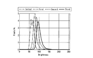
- the luminance value distribution histograms obtained in Example 2 were approximated by the least square method and converted into luminance value distribution curves, which were combined into one graph.
- the graph is shown in FIG.
- “Initial” corresponds to the luminance value distribution histogram obtained before spraying the contamination promoting liquid
- “First”, “Second”, and “Third” are 1 cycle, 2 cycles, and 3 cycles, respectively. It is a luminance value distribution curve corresponding to the luminance value distribution histogram obtained later.
- Ra When the etching time was 10 to 30 seconds, Ra was 10 to 50 nm, and when it was 0 seconds or 40 seconds or more, it was less than 10 nm.
- the reason why Ra is reduced when the etching time is 40 seconds or longer is considered to be that the portion masked with wax is also etched, and the height of the protrusion is reduced. Note that the difference in Ra when the etching time is 10 seconds, 20 seconds, and 30 seconds is considered to be due to the influence of variations in the deposited wax rather than the etching time.
- the transparent member of Example 2 had the smallest ratio of bright spots having high luminance values in the luminance value distribution measured after three cycles. Also, the dispersion was a small distribution. The value of ⁇ shown in Table 1 was also the smallest value for the transparent member of Example 2.
- Examples 7 to 13 (Preparation of desalted sodium silicate solution) While stirring 237.5 g of distilled water, sodium silicate 4 (manufactured by Nippon Chemical Industry Co., Ltd., SiO 2 : 24.0 mass%, Na 2 O: 7.0 mass%. SiO 2 / Na 2 O 62.5 g of a molar ratio of 3.5 / 1) and 180 g of cation exchange resin (Diaion SK1BH, manufactured by Mitsubishi Chemical Corporation) were added in this order, and the mixture was stirred for 10 minutes or more and then cation exchange resin by suction filtration. And a desalted sodium silicate solution having a solid content concentration of 5% by mass in terms of silicon oxide was obtained.
- sodium silicate 4 manufactured by Nippon Chemical Industry Co., Ltd., SiO 2 : 24.0 mass%, Na 2 O: 7.0 mass%.
- 180 g of cation exchange resin
- TiO 2 film forming composition (Preparation of TiO 2 film forming composition) While stirring 5.32 g of 2-propanol, 1.85 g of the titania particle dispersion (STK-01, manufactured by Ishihara Sangyo Co., Ltd.) and 2.18 g of the desalted sodium silicate solution were added in this order.
- a forming composition was prepared.
- a soda lime glass plate (manufactured by Asahi Glass Co., Ltd., product number FL3.5, length 100 mm, width 100 mm, thickness 3.5 mm) was set on a spin coater, and the TiO 2 film forming composition was placed on the soda lime glass plate. 2.0 g of the solution was dropped onto the surface of the substrate, spin-coated, and then baked at 300 ° C. for 30 minutes to produce a glass plate (precursor) with a TiO 2 film.
- FIG. 1 Manufacture of transparent substrate
- a micro fog spray gun YSG-05 nozzle diameter 0.5 ⁇ m
- ICC micro fog spray gun
- Slurry A dispersion in which 11 kinds of test powders 1 (Kanto loam, median diameter 1.6 to 2.3 ⁇ m) defined in JIS Z 8901: 2006 are dispersed in water at a concentration of 1% by mass.
- the TiO 2 film-coated glass plate to setting the base towards the surface of the TiO 2 film side to the spray device.
- Wet blasting is performed by spraying the slurry from a position 20 mm away from the surface while moving the spraying device carefully so that there is no gap in the center of the TiO 2 film-coated glass plate of 35 mm ⁇ 30 mm. It was.
- the spraying is performed from a position 20 mm away from the surface of the TiO 2 film, the compressor pressure is 0.4 MPa, the slurry flow rate is 318 m / second, the slurry spraying time (blast time) is 15 seconds, 30 seconds, 60 seconds, 180 seconds. For 480 seconds or 720 seconds.
- the blast time of 15 to 720 seconds in this example is 1.4 to 68.6 seconds / cm 2 as the processing time per unit area.
- FIG. 7 is a graph in which the horizontal axis represents the blast time (unit: seconds) of the wet blast treatment, and the vertical axis represents the measured values (unit: nm) of Ra and Rq.
- Example 7 the antifouling property was evaluated for the transparent members of Example 7 and Example 9 by the same procedure as Example 1.
- the results (RMS value ⁇ ) are shown in Table 2.
- FIG. 8 is a photograph of the transparent substrate of Example 9 after the outdoor exposure test
- FIG. 9 is a photograph of the soda lime glass plate after the outdoor exposure test.
- the area within the square near the center is a portion subjected to wet blasting, and the outside is a portion not subjected to wet blasting.
Landscapes
- Chemical & Material Sciences (AREA)
- Life Sciences & Earth Sciences (AREA)
- Engineering & Computer Science (AREA)
- Chemical Kinetics & Catalysis (AREA)
- General Chemical & Material Sciences (AREA)
- Geochemistry & Mineralogy (AREA)
- Materials Engineering (AREA)
- Organic Chemistry (AREA)
- General Physics & Mathematics (AREA)
- Physics & Mathematics (AREA)
- Health & Medical Sciences (AREA)
- Analytical Chemistry (AREA)
- Biochemistry (AREA)
- General Health & Medical Sciences (AREA)
- Mechanical Engineering (AREA)
- Immunology (AREA)
- Pathology (AREA)
- Surface Treatment Of Glass (AREA)
- Application Of Or Painting With Fluid Materials (AREA)
- Investigating Materials By The Use Of Optical Means Adapted For Particular Applications (AREA)
Abstract
防汚性に優れる透明部材を提供する。 透明部材の表面に対し、特定の手順による処理を3サイクル行い、処理前および各サイクル後に、該表面に光を照射し、該表面を撮像して画像データを取得し、該画像データに基づいて輝度値分布ヒストグラムを作成し、処理前に得られた輝度値分布ヒストグラムにおける前記透明部材のピクセル数の比率が最大となる輝度値をx0、3サイクル後に得られた輝度値分布ヒストグラムについて、ピクセル数の比率に対応した輝度値をxiとし、下式(1)により求められる二乗平均平方根値σが40以下である表面を有する透明部材。iはピクセル数の比率を示し、0~100の整数である。nはピクセル数の比率の最大値を示し、100である。
Description
本発明は、透明部材、透明部材の製造方法および透明部材の表面の汚れ具合を評価する評価方法に関する。
ガラス板等の透明部材は、建造物の窓や車両のフロントガラス、太陽電池のカバーガラスなど様々な用途で使用されている。
屋外で用いられる透明部材に大気中の汚れが付着し堆積すると、外観や透光性が低下する。透光性の低下は視認性や発電効率の低下を招く。
汚れの付着および堆積を抑制するために、透明部材に防汚性を付与することが提案されている。防汚性の付与方法としては、たとえば、表面に撥水性または親水性(撥油性)のコーティングを設けて、汚れの付着を防ぐ方法が提案されている(たとえば特許文献1)。
屋外で用いられる透明部材に大気中の汚れが付着し堆積すると、外観や透光性が低下する。透光性の低下は視認性や発電効率の低下を招く。
汚れの付着および堆積を抑制するために、透明部材に防汚性を付与することが提案されている。防汚性の付与方法としては、たとえば、表面に撥水性または親水性(撥油性)のコーティングを設けて、汚れの付着を防ぐ方法が提案されている(たとえば特許文献1)。
透明部材の防汚性の評価方法としては、汚染促進液(関東ロームの水分散液等)を噴霧するなどして透明部材の表面を汚染させ、その後、透明部材のへイズ値や表面のグロス値を測定する方法がある(たとえば特許文献2の実施例等)。
しかし、ヘイズ値やグロス値による評価は、たとえば局所的に大きく汚れる場合と、全体的に薄く汚れる場合との区別ができない。そのため、このような指標で良好な防汚性を示した透明部材でも、実際には汚れて見えることがある。
しかし、ヘイズ値やグロス値による評価は、たとえば局所的に大きく汚れる場合と、全体的に薄く汚れる場合との区別ができない。そのため、このような指標で良好な防汚性を示した透明部材でも、実際には汚れて見えることがある。
本発明は、防汚性に優れる透明部材を提供することを目的とする。
また、本発明は、防汚性に優れる透明部材が得られる製造方法を提供することを目的とする。
また、本発明は、目視評価と良好な対応を示す透明部材の表面の汚れ具合の評価方法を提供することを目的とする。
また、本発明は、防汚性に優れる透明部材が得られる製造方法を提供することを目的とする。
また、本発明は、目視評価と良好な対応を示す透明部材の表面の汚れ具合の評価方法を提供することを目的とする。
本発明は以下の態様を有する。
[1]以下の方法(I)により求められる二乗平均平方根値σが40以下である表面を有する透明部材。
方法(I):暗室内で、透明部材の表面に対し、照度20000ルクスの光を、該表面に平行な方向から裏面側に5°傾斜した角度で照射し、該表面上の、前記光の照射方向と直交する方向に設置された撮像手段で該表面を撮像して該表面の画像データを得、該画像データから無作為に抽出される15mm×15mmの大きさの領域2箇所を画像処理ソフトにより解析し、横軸に256階調の輝度値、縦軸にピクセル数の比率をとった輝度値分布ヒストグラムを作成する。該輝度値分布ヒストグラムにおけるビンの幅は1とする。該輝度値分布ヒストグラムにおける前記透明部材のピクセル数の比率が最大となる輝度値をx0とする。
次いで、前記透明部材の表面に以下の汚染促進液を、以下の噴霧装置を用いて5秒間噴霧し、60℃で1時間乾燥させた後、該表面に水道水を、前記噴霧装置を用いて180秒間噴霧し、60℃で1時間乾燥させる工程を1サイクルとして3サイクル実施する。3サイクル後に、暗室内で、前記表面に対し、前記と同じ手順で照度20000ルクスの光を照射し、該表面を撮像して該表面の画像データを得、該画像データから無作為に抽出される15mm×15mmの大きさの領域2箇所を画像処理ソフトにより解析し、横軸に256階調の輝度値、縦軸にピクセル数をとった輝度値分布ヒストグラムを作成する。3回目のサイクル後に得られた輝度値分布ヒストグラムについて、ピクセル数の比率に対応した輝度値をxiとする。
汚染促進液:JIS Z 8901(2006)に規定される試験用粉体1の11種(関東ローム、中位径1.6~2.3μm)を0.1質量%の濃度で水に分散させた分散液。
噴霧装置:噴霧される液滴の粒径が10μmで、噴霧量が20g/分で、前記表面から600mm離れた位置に設置された2流体ノズルスプレーガン。
前記x0およびxiから下式(1)により二乗平均平方根値σを算出する。
iはピクセル数の比率を示し、0~100の整数である。nはピクセル数の比率の最大値を示し、100である。
[2]前記二乗平均平方根値σが40以下である表面が、凹凸が存在する表面であり、該表面の突起密度が0.1~100個・μm-2で、算術平均面粗さ(Ra)が2~60nmで、水接触角が0~10°である、[1]に記載の透明部材。
[3]前記二乗平均平方根値σが40以下である表面が、親水性コーティング膜を有する表面である、[1]または[2]に記載の透明部材。
[4]前記親水性コーティング膜の厚さが0.01~1.00μmである、[3]に記載の透明部材。
[5]前記透明部材がガラス板である、[1]~[4]のいずれかに記載の透明部材。
[3]前記二乗平均平方根値σが40以下である表面が、親水性コーティング膜を有する表面である、[1]または[2]に記載の透明部材。
[4]前記親水性コーティング膜の厚さが0.01~1.00μmである、[3]に記載の透明部材。
[5]前記透明部材がガラス板である、[1]~[4]のいずれかに記載の透明部材。
[6]凹凸が存在する表面を有し、前記凹凸が存在する表面の算術平均面粗さ(Ra)が8.5~30nm、二乗平均平方根粗さ(Rq)が11~30nmである透明部材。
[7]前記凹凸が存在する表面の突起密度が0.1~100個・μm-2である、[6]に記載の透明部材。
[8]前記凹凸が存在する表面が親水性コーティング膜を有する表面であり、該表面の水接触角が0~10°である、[6]または[7]に記載の透明部材。
[9]前記親水性コーティング膜の厚さが0.01~1.00μmである、[6]~[8]のいずれかに記載の透明部材。
[10]前記親水性コーティング膜が親水性ポリマーの膜である、[6]~[9]のいずれかに記載の透明部材。
[11]前記親水性コーティング膜が酸化チタン膜である、[6]~[9]のいずれかに記載の透明部材。
[12]前記透明部材がガラス板である、[6]~[11]のいずれかに記載の透明部材。
[13]表面に親水性コーティング膜を有するガラス板の、前記親水性コーティング膜表面に、以下のウェットブラスト処理を施す、透明部材の製造方法。
ウェットブラスト処理:粒子を分散させた液体を前記親水性コーティング膜表面に吹き付けることにより、前記親水性コーティング膜表面に算術平均面粗さ(Ra)が8.5~30nmかつ二乗平均平方根粗さ(Rq)が11~30nmの凹凸を形成する処理。
[14]撥水性パターン膜を有するガラス板の前記撥水性パターン膜を有する面をエッチング溶液でウェットエッチング処理して前記ガラス板の表面に凹凸を形成し、次いで前記撥水性パターン膜を除去した後、前記凹凸が形成された表面に親水性コート剤を塗布して親水性コーティング膜を形成する透明部材の製造方法であって、
前記撥水性パターン膜を有する面のウェットエッチング処理が、前記親水性コーティング膜が形成された面の算術平均面粗さ(Ra)が8.5~30nmかつ二乗平均平方根粗さ(Rq)が11~30nmとなるように行われる、透明部材の製造方法。
[15]汚れ物質を含む液を透明部材の表面に噴霧して汚れを付着させ、水洗した後、
前記汚れを付着させた表面に光を照射し、該表面を撮像手段により撮像して画像データを取得し、該画像データに基づいて輝度値分布を作成し、
前記輝度値分布において、予め設定した閾値以上の輝度値の積算値と、輝度値分布全体の積算値との比から、前記表面の汚れ具合を評価する評価方法。
本発明の透明部材は、防汚性に優れる。
本発明の透明部材の製造方法によれば、防汚性に優れる透明部材が得られる。
本発明の評価方法により透明部材の表面の汚れ具合を評価すれば、目視評価と良好な対応を示す評価結果が得られる。
本発明の透明部材の製造方法によれば、防汚性に優れる透明部材が得られる。
本発明の評価方法により透明部材の表面の汚れ具合を評価すれば、目視評価と良好な対応を示す評価結果が得られる。
以下の用語の定義は、本明細書および特許請求の範囲にわたって適用される。
透明部材における「透明」とは、400~1100nmの波長領域の光を平均して80%以上透過することを意味する。
「突起密度」は、隣接する凸部分と凹部分の高さが2nm以上のものを突起と定義した時の、単位面積当たりの突起数(単位:個・μm-2)を意味する。
「算術平均面粗さ(Ra)」、「二乗平均平方根粗さ(Rq)」はそれぞれ、原子間力顕微鏡(AFM)により測定される値である。
「水接触角」は、接触角計を用い、液滴(水滴)のサイズを20μLに設定して測定される値である。
透明部材における「透明」とは、400~1100nmの波長領域の光を平均して80%以上透過することを意味する。
「突起密度」は、隣接する凸部分と凹部分の高さが2nm以上のものを突起と定義した時の、単位面積当たりの突起数(単位:個・μm-2)を意味する。
「算術平均面粗さ(Ra)」、「二乗平均平方根粗さ(Rq)」はそれぞれ、原子間力顕微鏡(AFM)により測定される値である。
「水接触角」は、接触角計を用い、液滴(水滴)のサイズを20μLに設定して測定される値である。
≪汚れ具合の評価方法≫
本発明の評価方法では、汚れ物質を含む液(以下、「汚染促進液」ともいう。)を透明部材の表面に噴霧して汚れを付着させ、水洗した後、
前記汚れを付着させた表面に光を照射し、該表面を撮像手段により撮像して画像データを取得し、該画像データに基づいて輝度値分布を作成し、
前記輝度値分布において、予め設定した閾値以上の輝度値の積算値と、輝度値分布全体の積算値との比から、前記表面の汚れ具合を評価する。
本発明の評価方法では、汚れ物質を含む液(以下、「汚染促進液」ともいう。)を透明部材の表面に噴霧して汚れを付着させ、水洗した後、
前記汚れを付着させた表面に光を照射し、該表面を撮像手段により撮像して画像データを取得し、該画像データに基づいて輝度値分布を作成し、
前記輝度値分布において、予め設定した閾値以上の輝度値の積算値と、輝度値分布全体の積算値との比から、前記表面の汚れ具合を評価する。
本発明の評価方法においては、汚染促進液の噴霧および水洗後に表面に付着している汚れに、照射された光が当たり散乱する。
そのため、光の照射下で表面を撮像して得られる画像では、表面に付着した汚れが白い輝点として観察される。つまり輝点の数が、付着した汚れの数であると判定できる。
また、付着した汚れが大きいほど、散乱光が強くなり、輝点の輝度値が大きくなる。そのため、画像上での輝度値が大きいものほど、大きく目立つ汚れであると判定できる。
そのため、光の照射下で表面を撮像して得られる画像では、表面に付着した汚れが白い輝点として観察される。つまり輝点の数が、付着した汚れの数であると判定できる。
また、付着した汚れが大きいほど、散乱光が強くなり、輝点の輝度値が大きくなる。そのため、画像上での輝度値が大きいものほど、大きく目立つ汚れであると判定できる。
本発明の評価方法は、たとえば、図1~2に示す装置を用いて実施できる。
図1は、噴霧装置およびこれを用いた噴霧方法を説明する概略図である。
図2は、透明部材の表面の撮像および画像解析に用いる装置の概略構成図である。
図1は、噴霧装置およびこれを用いた噴霧方法を説明する概略図である。
図2は、透明部材の表面の撮像および画像解析に用いる装置の概略構成図である。
噴霧装置10は、汚染促進液または水道水を収容するタンク11と、タンク11に取り付けられた2流体ノズル12と、2流体ノズル12にエアを供給するコンプレッサ13とを備える。
汚染促進液および水道水が噴霧される透明部材20は、高さ調節用の台14の上に、固定台15により、水平面に対して垂直に設置されている。透明部材20の表面と、2流体ノズル12の先端との間の距離は600mmで、汚染促進液または水道水の噴霧方向の中心(2流体ノズル12の先端の位置)と透明部材20の中心とは一致している。
汚染促進液および水道水が噴霧される透明部材20は、高さ調節用の台14の上に、固定台15により、水平面に対して垂直に設置されている。透明部材20の表面と、2流体ノズル12の先端との間の距離は600mmで、汚染促進液または水道水の噴霧方向の中心(2流体ノズル12の先端の位置)と透明部材20の中心とは一致している。
透明部材の表面への光の照射、表面の撮像および画像解析に用いる装置は、暗室内に設置されており、目視検査用ライト31と、デジタルカメラ(撮像手段)32と、デジタルカメラ32および透明部材20を固定する固定具33と、オープンソースでパブリックドメインの画像処理ソフトであるImageJ(開発元:Wayne Rasband、2014年6月27日版)がインストールされたコンピュータ34とを備える。
目視検査用ライト31は、固定具33の方向に、水平面に対して平行に光を照射するように設置されている。
デジタルカメラ32は、レンズを、水平面に対して垂直方向下側(透明部材20側)に向けて固定具33に固定されている。また、コンピュータ34に接続されており、撮像した写真のデータをコンピュータ34に入力できるようになっている。
目視検査用ライト31からの光の照射方向と、デジタルカメラ32のレンズが向けられている方向とは直交している。
目視検査用ライト31は、固定具33の方向に、水平面に対して平行に光を照射するように設置されている。
デジタルカメラ32は、レンズを、水平面に対して垂直方向下側(透明部材20側)に向けて固定具33に固定されている。また、コンピュータ34に接続されており、撮像した写真のデータをコンピュータ34に入力できるようになっている。
目視検査用ライト31からの光の照射方向と、デジタルカメラ32のレンズが向けられている方向とは直交している。
目視検査用ライト31としては、照度15000~25000ルクス程度の光を照射可能なものが好ましい。
デジタルカメラ32としては、たとえば、有効画素数1500万画素以上、センサーサイズAPS-Cを備えるものが挙げられる。
評価の間、デジタルカメラ32の設定は変更しない。
評価の間、デジタルカメラ32の設定は変更しない。
固定具33は、水平面に対して垂直に設置された棒状の器具で、上部にカメラ固定部を備え、それよりも下側に透明部材固定部を備える。透明部材固定部の高さは、目視検査用ライト31の高さとほぼ同じである。
透明部材固定部は、透明部材20を表面側および裏面側から挟持し、また、目視検査用ライト31からの光の照射方向に対する透明部材20の表面の角度を調整できるように構成されている。
透明部材固定部は、透明部材20を表面側および裏面側から挟持し、また、目視検査用ライト31からの光の照射方向に対する透明部材20の表面の角度を調整できるように構成されている。
図1~2に示す装置を用いた評価方法は、たとえば以下の手順で実施できる。
噴霧装置10を2つ用意し、一方の噴霧装置10のタンク11内に汚染促進液を、他方の噴霧装置10のタンク11内に水道水を収容する。
透明部材20を固定台15に設置し、該固定台15を台14の上に設置する。これにより、透明部材20が、表面を噴霧装置10側に向けて、水平面に対して垂直に設置される。
次いで、透明部材20の表面と対向する位置に、汚染促進液を収容した噴霧装置10を設置し、その位置から透明部材20の表面に汚染促進液を噴霧し、乾燥させる。乾燥後、汚染促進液を収容した噴霧装置10を、水道水を収容した噴霧装置10に入れ替えて、透明部材20の表面に水道水を噴霧し、乾燥させる。以上の汚染促進液の噴霧および乾燥ならびに水道水の噴霧および乾燥を1サイクルとし、必要に応じて2サイクル以上実施する。
透明部材20の表面と、噴霧装置10の2流体ノズル12の先端との間の距離Dは、汚染促進液および水道水が透明部材20の表面全体に噴霧されるように、適宜設定される。
サイクル数は、1~5回が好ましく、効率の点では3回が特に好ましい。
前記のサイクルを実施する前および前記のサイクルを実施した後にそれぞれ、以下の手順で、輝度値分布ヒストグラムを作成する。
まず、透明部材20を、暗室内の固定具33に、表面20aを上側(デジタルカメラ32側)に向け、目視検査用ライト31からの光の照射方向D1と透明部材20の表面20aとがなす角度θ1が所望の値になるように固定する。角度θ1は、-5~30°が好ましい。
ここで、角度θ1が正の値である場合は、目視検査用ライト31から照射された光が透明部材20の裏面20b側から入射することを示す。角度θ1が負の値である場合は、目視検査用ライト31から照射された光が透明部材20の表面20a側から入射することを示す。
図3に、角度θ1が正の値である場合の透明部材20の配置を示す。
光の照射方向D1と、デジタルカメラ32のレンズが向けられている方向D2とは直交している。
図3に、角度θ1が正の値である場合の透明部材20の配置を示す。
光の照射方向D1と、デジタルカメラ32のレンズが向けられている方向D2とは直交している。
次いで、目視検査用ライト31から光を照射し、その状態で、固定具33に固定されたデジタルカメラ32により透明部材20の表面20aを撮像し、表面20aの画像データを得る。
得られた画像データはコンピュータ34に入力され、該画像データまたは該画像データから抽出される1以上の領域が画像処理ソフトImageJにより解析され、横軸に2m階調の輝度値、縦軸にピクセル数の比率をとった輝度値分布ヒストグラムが作成される。
mは、6~20であり、8~16が好ましい。mが大きいほど、より細かい輝度値の情報を得ることができる。汚れと基材の差が充分に判別されるという点では、mが8(256階調)以上であることが好ましい。
得られた画像データはコンピュータ34に入力され、該画像データまたは該画像データから抽出される1以上の領域が画像処理ソフトImageJにより解析され、横軸に2m階調の輝度値、縦軸にピクセル数の比率をとった輝度値分布ヒストグラムが作成される。
mは、6~20であり、8~16が好ましい。mが大きいほど、より細かい輝度値の情報を得ることができる。汚れと基材の差が充分に判別されるという点では、mが8(256階調)以上であることが好ましい。
ただし、本発明の評価方法は、上記の手順によるものに限定されない。上記手順における各構成及びそれらの組み合わせ等は一例であり、本発明の趣旨を逸脱しない範囲内で、構成の付加、省略、置換、およびその他の変更が可能である。
たとえば、撮像手段はデジタルカメラに限定されず、フィルムカメラ等であってもよい。
ImageJ以外の画像処理ソフトを用いてもよい。
たとえば、撮像手段はデジタルカメラに限定されず、フィルムカメラ等であってもよい。
ImageJ以外の画像処理ソフトを用いてもよい。
従来、透明部材の防汚性の評価には、サンプルの1点に対して光を当て、積分球にて拡散光および全光線透過率を測定し、全光線透過率に対する拡散光の比率(%)として求められるヘイズ値が汎用されている。しかし、1点光で評価されるため、サンプルの表面にて汚れの具合にムラがあるような場合、測定結果は必ずしも実際の汚れの具合を反映しない。
本発明の評価方法にあっては、ある程度の大きさのある画像から汚れ具合を判定するため、従来の方法に比べて、より実際の汚れ具合に対応した評価結果が得られる。
本発明の評価方法にあっては、ある程度の大きさのある画像から汚れ具合を判定するため、従来の方法に比べて、より実際の汚れ具合に対応した評価結果が得られる。
≪透明部材≫
<第一の態様の透明部材>
本発明の第一の態様の透明部材(以下、「透明部材(A)」ともいう。)は、以下の方法(I)により求められる二乗平均平方根値(RMS値)σが40以下である表面を有する。
<第一の態様の透明部材>
本発明の第一の態様の透明部材(以下、「透明部材(A)」ともいう。)は、以下の方法(I)により求められる二乗平均平方根値(RMS値)σが40以下である表面を有する。
方法(I):
暗室内で、透明部材の表面に対し、目視検査用ライトを用いて照度20000ルクスの光を、該表面に平行な方向から裏面側に5°傾斜した角度で照射し、該表面上の、前記光の照射方向と直交する方向に設置された撮像手段で該表面を撮像して該表面の画像データを得る。
該画像データから無作為に抽出される15mm×15mmの大きさの領域2箇所を画像処理ソフトにより解析し、横軸に256階調の輝度値、縦軸にピクセル数の比率をとった輝度値分布ヒストグラムを作成する。該輝度値分布ヒストグラムにおけるビンの幅は1とする。
該輝度値分布ヒストグラムにおける前記透明部材(汚染前の透明部材)のピクセル数の比率が最大となる輝度値をx0とする。
次いで、前記透明部材の表面に以下の汚染促進液を、以下の噴霧装置を用いて5秒間噴霧し、60℃で1時間乾燥させた後、該表面に水道水を、前記噴霧装置を用いて180秒間噴霧し、60℃で1時間乾燥させる工程を1サイクルとして3サイクル実施する。
3サイクル後に、暗室内で、前記表面に対し、前記と同じ手順で照度20000ルクスの光を照射し、該表面を撮像して該表面の画像データを得、該画像データから無作為に抽出される15mm×15mmの大きさの領域2箇所を画像処理ソフトにより解析し、横軸に256階調の輝度値、縦軸にピクセル数の比率をとった輝度値分布ヒストグラムを作成する。
3回目のサイクル後に得られた輝度値分布ヒストグラムについて、各ピクセル数の比率に対応した輝度値をxiとする。
ピクセル数の比率が同じである2つ以上の輝度値が存在する場合は、各々の輝度値をxiとして式(1)にあてはめて計算する。
3サイクル後に、暗室内で、前記表面に対し、前記と同じ手順で照度20000ルクスの光を照射し、該表面を撮像して該表面の画像データを得、該画像データから無作為に抽出される15mm×15mmの大きさの領域2箇所を画像処理ソフトにより解析し、横軸に256階調の輝度値、縦軸にピクセル数の比率をとった輝度値分布ヒストグラムを作成する。
3回目のサイクル後に得られた輝度値分布ヒストグラムについて、各ピクセル数の比率に対応した輝度値をxiとする。
ピクセル数の比率が同じである2つ以上の輝度値が存在する場合は、各々の輝度値をxiとして式(1)にあてはめて計算する。
汚染促進液:JIS Z 8901(2006)に規定される試験用粉体1の11種(関東ローム、中位径1.6~2.3μm)を0.1質量%の濃度で水に分散させた分散液。
噴霧装置:噴霧される液滴の粒径が10μmで、噴霧量が20g/分で、前記表面から600mm離れた位置に設置された2流体ノズルスプレーガン。
噴霧装置:噴霧される液滴の粒径が10μmで、噴霧量が20g/分で、前記表面から600mm離れた位置に設置された2流体ノズルスプレーガン。
求めたx0およびxiから下式(1)によりRMS値σを算出する。
ただし、式(1)中のiはピクセル数の比率を示し、1刻みで0から100までの整数をとる。nはピクセル数の比率の最大値を示し、100である。

ただし、式(1)中のiはピクセル数の比率を示し、1刻みで0から100までの整数をとる。nはピクセル数の比率の最大値を示し、100である。
方法(I)は、前述の図1~2に示す装置を用いて実施できる。
方法(I)においては、本発明の評価方法において説明したように、汚染促進液の噴霧により表面に付着し、水道水の噴霧により除去されなかった汚れが、該表面を撮像して得られる画像にて、白い輝点として観察される。また、付着した汚れが大きいほど、光を強く受けて散乱光が強くなり、輝点の輝度値が大きくなる。
前述の式(1)により求めたRMS値σが小さいほど、汚れ具合が汚染促進液を噴霧する前の状態に近い。つまり汚れが付着しにくいか、付着した汚れが水洗、降雨等により除去されやすい。
したがって、透明部材(A)は、屋外において、表面に大きな目立つ汚れが堆積しにくく、長期間屋外に置かれても外観や透光性が低下しにくい。また、汚れを除去するための洗浄コストが少ない。
前記RMS値σは、透明部材の表面の親水性、表面形状等によって調整できる。
たとえば透明部材の表面が疎水性の場合よりも親水性の方が、RMS値σが小さい傾向がある。
透明部材の表面に凹凸が形成されていると、凹凸が形成されていない場合に比べて、RMS値σが小さい傾向がある。
表面に凹凸が形成されている場合、凹凸の大きさ、複数の凸部または凹部の間の間隔、凹凸の形状等によってRMS値σを調整できる。
たとえば透明部材の表面が疎水性の場合よりも親水性の方が、RMS値σが小さい傾向がある。
透明部材の表面に凹凸が形成されていると、凹凸が形成されていない場合に比べて、RMS値σが小さい傾向がある。
表面に凹凸が形成されている場合、凹凸の大きさ、複数の凸部または凹部の間の間隔、凹凸の形状等によってRMS値σを調整できる。
透明部材(A)は、表面の突起密度が0.1~100個・μm-2で、算術平均面粗さ(Ra)が2~60nmで、水接触角が0~10°であることが好ましく、突起密度が0.2~100個・μm-2で、算術平均面粗さ(Ra)が2~50nmで、水接触角が0~8°であることがより好ましく、突起密度が0.4~100個・μm-2で、算術平均面粗さ(Ra)が2~45nmで、水接触角が0~5°であることがさらに好ましい。
表面の突起密度、算術平均面粗さおよび水接触角がそれぞれ前記の範囲内であれば、前記RMS値σが40以下となりやすい。
表面の突起密度、算術平均面粗さおよび水接触角がそれぞれ前記の範囲内であれば、前記RMS値σが40以下となりやすい。
透明部材(A)としては、基材と、前記基材上に設けられた親水性コーティング膜とを有し、前記親水性コーティング膜が設けられた部分の表面に凹凸が存在し、前記凹凸が存在する表面が、前記RMS値σが40以下の表面である透明基材(以下、「透明基材(A1)」ともいう。)が好ましい。
基材、親水性コーティング膜としてはそれぞれ後述する第一実施形態に示すものが挙げられる。基材としてはガラス板が好ましい。
基材、親水性コーティング膜としてはそれぞれ後述する第一実施形態に示すものが挙げられる。基材としてはガラス板が好ましい。
透明基材(A1)において、前記親水性コーティング膜が設けられた部分の表面の凹凸の形成方法としては、例えば、後述する第一実施形態に示すように、表面に凹凸が形成されたガラス板上に親水性コーティング膜を形成する方法、後述する第二の態様の透明部材の製造方法に示すように、ウェットブラスト処理により形成する方法等が挙げられる。
これらのうち、ウェットブラスト処理により形成する方法が好ましい。前記凹凸が、ウェットブラスト処理により形成されたものであれば、防汚性がより優れる。
ウェットブラスト処理は、前記被処理面の算術平均面粗さ(Ra)が8.5~30nm、二乗平均平方根粗さ(Rq)が11~30nmとなるように行われることが好ましく、前記被処理面の算術平均面粗さ(Ra)が8.5~25nm、二乗平均平方根粗さ(Rq)が11~25nmとなるように行われることがより好ましい。
これらのうち、ウェットブラスト処理により形成する方法が好ましい。前記凹凸が、ウェットブラスト処理により形成されたものであれば、防汚性がより優れる。
ウェットブラスト処理は、前記被処理面の算術平均面粗さ(Ra)が8.5~30nm、二乗平均平方根粗さ(Rq)が11~30nmとなるように行われることが好ましく、前記被処理面の算術平均面粗さ(Ra)が8.5~25nm、二乗平均平方根粗さ(Rq)が11~25nmとなるように行われることがより好ましい。
以下、添付の図面を用い、実施形態を示して透明部材(A)を説明する。
〔第一実施形態〕
図4は、透明部材(A)の第一実施形態を模式的に示す断面図である。
第一実施形態の透明部材1は、表面に凹凸が形成された基材3と、基材3の表面に形成された親水性コーティング膜5とを有する。
透明部材1の前記方法(I)により求められるRMS値σは40以下である。
図4は、透明部材(A)の第一実施形態を模式的に示す断面図である。
第一実施形態の透明部材1は、表面に凹凸が形成された基材3と、基材3の表面に形成された親水性コーティング膜5とを有する。
透明部材1の前記方法(I)により求められるRMS値σは40以下である。
(基材)
基材3は、透明なものであれば特に限定されない。ここでの「透明」は透明部材における「透明」と同義である。
基材3の形態としては、たとえば板、フィルム等が挙げられる。板状の場合、図示のような平板状のものに限らず、全面または一部に曲率を有していてもよい。
基材3の材料としては、たとえばガラス、樹脂等が挙げられる。
ガラスとしては、たとえばソーダライムガラス、ホウケイ酸ガラス、アルミノシリケートガラス、無アルカリガラス等が挙げられる。
樹脂としては、たとえばポリエチレンテレフタレート、ポリカーボネート、トリアセチルセルロース、ポリメタクリル酸メチル等が挙げられる。
基材3は、透明なものであれば特に限定されない。ここでの「透明」は透明部材における「透明」と同義である。
基材3の形態としては、たとえば板、フィルム等が挙げられる。板状の場合、図示のような平板状のものに限らず、全面または一部に曲率を有していてもよい。
基材3の材料としては、たとえばガラス、樹脂等が挙げられる。
ガラスとしては、たとえばソーダライムガラス、ホウケイ酸ガラス、アルミノシリケートガラス、無アルカリガラス等が挙げられる。
樹脂としては、たとえばポリエチレンテレフタレート、ポリカーボネート、トリアセチルセルロース、ポリメタクリル酸メチル等が挙げられる。
基材3としては、耐紫外線(UV)性、耐熱性に優れる点で、ガラス板が好ましい。
ガラス板は、平坦な形状のガラス板のみでなく、曲面を有する形状のガラス板でもよい。ガラス板は、化学強化ガラス板、風冷強化ガラス板等の強化ガラス板であってもよい。
ガラス板は、平坦な形状のガラス板のみでなく、曲面を有する形状のガラス板でもよい。ガラス板は、化学強化ガラス板、風冷強化ガラス板等の強化ガラス板であってもよい。
基材3の表面(親水性コーティング膜5側の面)には凹凸が形成されている。
基材3の表面形状としては、複数の凸部および/または凹部がランダムに分布した形状、複数の凸部および/または凹部が規則的に配列した形状等が挙げられる。複数の凸部および/または凹部の形状や大きさは、同じでもよく異なってもよい。
凸部としては、基材3の表面に延在する長尺の凸条、点在する突起等が挙げられる。凹部としては、基材3の表面に延在する長尺の溝、点在する穴等が挙げられる。
凸条または溝の形状としては、直線、曲線、折れ曲がり形状等が挙げられる。基材3の表面においては、複数の凸条または溝が平行に存在して縞状をなしていてもよい。凸条または溝の、長手方向に直交する方向の断面形状としては、三角形(V字形)等の多角形、半円形等が挙げられる。
突起の形状としては、三角錐形、四角錐形、六角錐形等の多角錐形、円錐形、半球形、多面体形、その他各種不定形等が挙げられる。
基材3の表面の突起密度は、0.1~100個・μm-2が好ましく、0.2~100個・μm-2がより好ましく、0.4~100個・μm-2がさらに好ましい。
基材3の表面の突起密度が前記範囲内であれば、該表面に形成される親水性コーティング膜の表面のRa、つまり透明部材1の表面の突起密度が後述の範囲内となりやすい。
基材3の表面の突起密度が前記範囲内であれば、該表面に形成される親水性コーティング膜の表面のRa、つまり透明部材1の表面の突起密度が後述の範囲内となりやすい。
基材3の表面の算術平均面粗さ(Ra)は、2~60nmが好ましく、2~50nmがより好ましく、2~45nmがさらに好ましく、8.5~30nmが特に好ましく、8.5~25nmが最も好ましい。
基材3の表面のRaが前記範囲内であれば、該表面に形成される親水性コーティング膜の表面のRa、つまり透明部材1の表面のRaが後述の範囲内となりやすい。
基材3の表面のRaが前記範囲内であれば、該表面に形成される親水性コーティング膜の表面のRa、つまり透明部材1の表面のRaが後述の範囲内となりやすい。
基材3の厚さは、特に限定されないが、0.3~15.0mmが好ましく、0.5~12.0mmがより好ましい。基材3の厚さが前記範囲の下限値以上であれば、基材の機械的強度に優れる。基材3の厚さが前記範囲の上限値以下であれば、透過率に優れる。
(親水性コーティング膜)
親水性コーティング膜5は、表面の親水性を高めるために設けられる。透明部材1の表面が親水性であることで、疎水性の汚れが付着しにくくなる。また、表面に付着した汚れが、降雨、水洗等により除去されやすくなる。
親水性コーティング膜5は、表面の親水性を高めるために設けられる。透明部材1の表面が親水性であることで、疎水性の汚れが付着しにくくなる。また、表面に付着した汚れが、降雨、水洗等により除去されやすくなる。
親水性コーティング膜5としては、たとえば、親水性コート剤から形成される膜等が挙げられる。形成される親水性の膜の材質としては、親水性ポリマー、シリカやチタニアなどの金属酸化物等が挙げられる。
親水性コート剤としては、たとえば、親水基を多数有するポリマーの溶液や分散液、シリカ粒子分散液、チタニア粒子分散液、アルコキシシランの部分加水分解物の溶液や分散液等が挙げられる。
親水性コート剤の市販品としては、大阪有機化学工業社製のLAMBICシリーズの親水性コート剤、石原産業社製の光触媒酸化チタンコーティング剤であるST-Kシリーズの親水性コート剤等が挙げられる。上記LAMBICシリーズの親水性コート剤から親水性ポリマーの膜が形成され、上記ST-Kシリーズの親水性コート剤から親水性の酸化チタン膜が形成される
親水性コート剤としては、たとえば、親水基を多数有するポリマーの溶液や分散液、シリカ粒子分散液、チタニア粒子分散液、アルコキシシランの部分加水分解物の溶液や分散液等が挙げられる。
親水性コート剤の市販品としては、大阪有機化学工業社製のLAMBICシリーズの親水性コート剤、石原産業社製の光触媒酸化チタンコーティング剤であるST-Kシリーズの親水性コート剤等が挙げられる。上記LAMBICシリーズの親水性コート剤から親水性ポリマーの膜が形成され、上記ST-Kシリーズの親水性コート剤から親水性の酸化チタン膜が形成される
親水性コーティング膜5の厚さは、0.01~1.00μmが好ましく、0.02~0.20μmがより好ましい。親水性コーティング膜5の厚さが前記範囲の下限値以上であれば、親水性に優れる。基材3の厚さが前記範囲の上限値以下であれば、視認性に優れる。
親水性コーティング膜5は、表面に凹凸が形成された基材3の表面に形成されるため、親水性コーティング膜5の表面、つまり透明部材1の表面には、基材3の表面と同様に、凹凸が存在する。
親水性コーティング膜5の表面の突起密度(透明部材1の表面の突起密度)は、0.1~100個・μm-2が好ましく、0.2~100個・μm-2がより好ましく、0.4~100個・μm-2がさらに好ましい。透明部材1の表面の突起密度が前記範囲内であれば、前記方法(I)により求められるRMS値σが40以下になりやすい。
透明部材1の表面の突起密度は、基材3の表面の突起密度によって調整できる。
透明部材1の表面の突起密度は、基材3の表面の突起密度によって調整できる。
透明部材1の表面の算術平均面粗さ(Ra)は、2~60nmが好ましく、2~50nmがより好ましく、2~45nmがさらに好ましい。透明部材1の表面のRaが前記範囲内であれば、前記方法(I)により求められるRMS値σが40以下になりやすい。
透明部材1の表面のRaは、基材3の表面のRaによって調整できる。
透明部材1の表面のRaは、基材3の表面のRaによって調整できる。
透明部材1の表面の水接触角は、0~10°が好ましく、0~8°がより好ましく、0~5°がさらに好ましい。透明部材1の表面の水接触角が前記範囲内であれば、前記方法(I)により求められるRMS値σが40以下になりやすい。
水接触角は、親水性コーティング膜5を形成する材料、基材3の表面形状(突起密度、Ra、突起形状等)等により調整できる。表面形状に関し、たとえば突起密度が大きいほど、水接触角が大きくなる傾向がある。Raが大きいほど、水接触角が大きくなる傾向がある。
水接触角は、親水性コーティング膜5を形成する材料、基材3の表面形状(突起密度、Ra、突起形状等)等により調整できる。表面形状に関し、たとえば突起密度が大きいほど、水接触角が大きくなる傾向がある。Raが大きいほど、水接触角が大きくなる傾向がある。
(透明部材の製造方法)
透明部材1の製造方法としては、特に限定されず、公知の方法が利用できる。
図5に、透明部材1の製造方法の一例を示す。この例の製造方法は、以下の工程(α1)~(α7)を含む。
(α1)ガラス板3Aの表面に撥水性コート剤を塗布して撥水性コーティング膜7Aを形成する(図5(a))。
(α2)撥水性コーティング膜7Aの上にワックスを蒸着する。ワックスは撥水性コーティング膜7Aに弾かれ、微細粒状に凝集し、島状のワックス部9Aが形成される(図5(b))。
(α3)ワックス部9Aをマスクとして撥水性コーティング膜7Aのプラズマエッチングを行う。これにより、撥水性コーティング膜7Aのワックス部9Aで覆われていない部分が除去され、上面形状が島状のワックス部9Aと略同一の撥水性パターン膜7Bが形成される(図5(c))。
(α4)ワックス部9Aおよび撥水性パターン膜7Bをマスクとしてガラス板3Aの表面を、フッ酸を含むエッチング溶液でウェットエッチングする。これにより、表面に凹凸が形成されたガラス板3Bと、ガラス板3Bの表面の突起を被覆する撥水性パターン膜7Bと、撥水性パターン膜7Bを被覆するワックス部9Aとを備える積層体が得られる(図5(d))。
(α5)前記積層体のワックス部9Aを除去する(図5(e))。
(α6)工程(α5)の後、プラズマエッチングにより、撥水性パターン膜7Bを除去する(図5(f))。
(α7)工程(α6)の後、ガラス板3Bの表面に親水性コート剤を塗布して親水性コーティング膜5を形成する(図5(g))。これにより、基材3としてガラス板3Bを備える透明部材1が得られる。
ガラス板3Aを構成するガラスとしては、前記と同様のものが挙げられる。
ガラス板3Aは、フロート法、フュージョン法、ダウンドロー法等により成形された平滑なガラス板であってもよく、型板ガラスであってもよい。また、平坦なガラス板のみでなく、曲面を有するガラス板でもよい。ガラス板3Aは強化ガラス板であってもよい。
ガラス板3Aは、フロート法、フュージョン法、ダウンドロー法等により成形された平滑なガラス板であってもよく、型板ガラスであってもよい。また、平坦なガラス板のみでなく、曲面を有するガラス板でもよい。ガラス板3Aは強化ガラス板であってもよい。
撥水性コート剤としては、たとえば、フッ素塗料、シリコーンオイル等が挙げられる。
撥水性コート剤の市販品としては、ダイキン社製のオプツール(登録商標)シリーズ、ダイキン社製のユニダインシリーズ等が挙げられる。
撥水性コート剤の市販品としては、ダイキン社製のオプツール(登録商標)シリーズ、ダイキン社製のユニダインシリーズ等が挙げられる。
撥水性コート剤の塗布は、ウェットコート法により行ってもよく、ドライコート法により行ってもよい。
ウェットコート法としては、たとえば、ロールコート法、キャスト法、ディップコート法(浸漬法)、スピンコート法、水上キャスト法、ダイコート法、ラングミュア・プロジェット法が挙げられる。
ドライコート法としては、真空蒸着法、CVD法、スパッタリング法等が挙げられる。
ウェットコート法としては、たとえば、ロールコート法、キャスト法、ディップコート法(浸漬法)、スピンコート法、水上キャスト法、ダイコート法、ラングミュア・プロジェット法が挙げられる。
ドライコート法としては、真空蒸着法、CVD法、スパッタリング法等が挙げられる。
親水性コート剤の塗布は、ウェットコート法により行ってもよく、ドライコート法により行ってもよい。
親水性コーティング膜5の形成方法としては、ディップコート法が好ましい。
親水性コーティング膜5の形成方法としては、ディップコート法が好ましい。
この製造方法において、ガラス板3Bの表面の突起密度、ひいては透明部材1の表面の突起密度は、ワックスの蒸着時間により調整できる。
ガラス板3Bの表面のRa、ひいては透明部材1の表面のRaは、工程(α4)の際のエッチング時間により調整できる。
ガラス板3Bの表面のRa、ひいては透明部材1の表面のRaは、工程(α4)の際のエッチング時間により調整できる。
以上、透明部材(A)について、第一実施形態を示して説明したが、本発明は上記実施形態に限定されない。上記実施形態における各構成及びそれらの組み合わせ等は一例であり、本発明の趣旨を逸脱しない範囲内で、構成の付加、省略、置換、およびその他の変更が可能である。
たとえば、第一実施形態の透明部材1は、基材3および親水性コーティング膜5以外の他の層をさらに有してもよい。他の層としては、たとえばアンダーコート層、応力緩和層、密着改善層、保護層等が挙げられる。アンダーコート層は、基材3がガラスの場合におけるアルカリバリア層やワイドバンドの低屈折率層としての機能を有する。
本発明の透明部材は、所望のRMS値σを有していれば、基材3のみから構成されてもよい。
たとえば、第一実施形態の透明部材1は、基材3および親水性コーティング膜5以外の他の層をさらに有してもよい。他の層としては、たとえばアンダーコート層、応力緩和層、密着改善層、保護層等が挙げられる。アンダーコート層は、基材3がガラスの場合におけるアルカリバリア層やワイドバンドの低屈折率層としての機能を有する。
本発明の透明部材は、所望のRMS値σを有していれば、基材3のみから構成されてもよい。
本発明の透明部材を製造する方法は上記の例に限定されない。
たとえば後述する本発明の透明部材の製造方法により製造してもよく、その他、第一実施形態に示した製造方法における工程(α1)~(α6)の代わりに、基材上に粒子分散剤をコーティングする方法や、基材表面をフッ酸等でウェットエッチングする方法等が挙げられる。
粒子分散剤をコーティングする方法の場合、粒子分散剤の材質、粒子径、コーティング条件(コーティング量等)等によって表面の突起密度、算術平均面粗さ(Ra)、水接触角等を調整できる。
たとえば後述する本発明の透明部材の製造方法により製造してもよく、その他、第一実施形態に示した製造方法における工程(α1)~(α6)の代わりに、基材上に粒子分散剤をコーティングする方法や、基材表面をフッ酸等でウェットエッチングする方法等が挙げられる。
粒子分散剤をコーティングする方法の場合、粒子分散剤の材質、粒子径、コーティング条件(コーティング量等)等によって表面の突起密度、算術平均面粗さ(Ra)、水接触角等を調整できる。
<第二の態様の透明部材>
本発明の第二の態様の透明部材(以下、「透明部材(B)」ともいう。)は、凹凸が存在する表面を有し、前記凹凸が存在する表面の算術平均面粗さ(Ra)が8.5~30nm、二乗平均平方根粗さ(Rq)が11~30nmである。
前記算術平均面粗さ(Ra)は、8.5~25nmが好ましい。
前記二乗平均平方根粗さ(Rq)は、11~25nmが好ましい。
凹凸が存在する表面の算術平均面粗さ(Ra)、二乗平均平方根粗さ(Rq)がそれぞれ前記の範囲内であれば、前記表面の防汚性が優れる。
本発明の第二の態様の透明部材(以下、「透明部材(B)」ともいう。)は、凹凸が存在する表面を有し、前記凹凸が存在する表面の算術平均面粗さ(Ra)が8.5~30nm、二乗平均平方根粗さ(Rq)が11~30nmである。
前記算術平均面粗さ(Ra)は、8.5~25nmが好ましい。
前記二乗平均平方根粗さ(Rq)は、11~25nmが好ましい。
凹凸が存在する表面の算術平均面粗さ(Ra)、二乗平均平方根粗さ(Rq)がそれぞれ前記の範囲内であれば、前記表面の防汚性が優れる。
透明部材(B)としては、たとえば、表面に親水性コーティング膜を有するガラス板(以下、前駆体ともいう。)の、前記親水性コーティング膜表面に後述のウェットブラスト処理を施して得られるもの(以下、「透明部材(B1)」ともいう。)が挙げられる。
本実施形態の透明部材において、前記凹凸が存在する表面は、前記RMS値σが40以下の表面であってもよく、RMS値σが40以下の表面でなくてもよい。RMS値σが40以下の表面であることが好ましい。
透明部材(B1)は、後述する本発明の透明部材の製造方法により製造できる。
ただし透明部材(B)を製造する方法は、算術平均面粗さ(Ra)が8.5~30nm、二乗平均平方根粗さ(Rq)が11~30nmの表面を形成できる方法であればよく、上記の例に限定されない。
本実施形態の透明部材において、前記凹凸が存在する表面は、前記RMS値σが40以下の表面であってもよく、RMS値σが40以下の表面でなくてもよい。RMS値σが40以下の表面であることが好ましい。
透明部材(B1)は、後述する本発明の透明部材の製造方法により製造できる。
ただし透明部材(B)を製造する方法は、算術平均面粗さ(Ra)が8.5~30nm、二乗平均平方根粗さ(Rq)が11~30nmの表面を形成できる方法であればよく、上記の例に限定されない。
≪透明部材の製造方法≫
本発明の透明部材の製造方法は、前駆体の親水性コーティング膜表面に以下のウェットブラスト処理を施すこと(以下、「工程(i)」ともいう。)を特徴とする。
ウェットブラスト処理:粒子を分散させた液体を親水性コーティング膜表面に吹き付けることにより、親水性コーティング膜表面に算術平均面粗さ(Ra)が8.5~30nmかつ二乗平均平方根粗さ(Rq)が11~30nmの凹凸を形成する処理。
本発明の透明部材の製造方法は、前駆体の親水性コーティング膜表面に以下のウェットブラスト処理を施すこと(以下、「工程(i)」ともいう。)を特徴とする。
ウェットブラスト処理:粒子を分散させた液体を親水性コーティング膜表面に吹き付けることにより、親水性コーティング膜表面に算術平均面粗さ(Ra)が8.5~30nmかつ二乗平均平方根粗さ(Rq)が11~30nmの凹凸を形成する処理。
(前駆体)
透明部材前駆体において、ガラス板、親水性コーティング膜としては、それぞれ、透明部材(A1)の説明で挙げたものと同様のものが挙げられる。
前駆体において、ガラス板の表面は、凹凸が形成されていてもよく、凹凸が形成されていなくてもよい。
前駆体は、例えば、前記工程(α7)のように、ガラス板の表面に親水性コート剤を塗布して親水性コーティング膜を形成することにより得られる。ガラス板と、前記ガラス板上に形成された親水性コーティング膜とを有するものが市販されていれば、これを前駆体として用いてもよい。
ウェットブラスト処理前の被処理面(前駆体の親水性コーティング膜が設けられた部分の表面)は、典型的には、算術平均面粗さ(Ra)が8.5nm未満、二乗平均平方根粗さ(Rq)が10nm未満である。
(工程(i))
工程(i)では、前駆体について、前記親水性コーティング膜が設けられた部分の表面を被処理面として前記ウェットブラスト処理を施す。
前駆体について前記ウェットブラスト処理を施すと、被処理面に凹凸が形成される。これにより、ガラス板と、前記ガラス板上に形成された親水性コーティング膜とを有し、前記親水性コーティング膜が設けられた部分の表面に凹凸が存在する透明部材が得られる。
ウェットブラスト処理では、粒子のみを被処理面に吹き付ける乾式ブラスト処理に比べ、小さい粒子を使用することができ、より微細な凹凸を形成させることができる。
工程(i)では、前駆体について、前記親水性コーティング膜が設けられた部分の表面を被処理面として前記ウェットブラスト処理を施す。
前駆体について前記ウェットブラスト処理を施すと、被処理面に凹凸が形成される。これにより、ガラス板と、前記ガラス板上に形成された親水性コーティング膜とを有し、前記親水性コーティング膜が設けられた部分の表面に凹凸が存在する透明部材が得られる。
ウェットブラスト処理では、粒子のみを被処理面に吹き付ける乾式ブラスト処理に比べ、小さい粒子を使用することができ、より微細な凹凸を形成させることができる。
工程(i)において、ウェットブラスト処理は、ウェットブラスト処理後の被処理面の算術平均面粗さ(Ra)が8.5~30nm、二乗平均平方根粗さ(Rq)が11~30nmとなるように行われる。
前記ウェットブラスト処理は、前記被処理面の算術平均面粗さ(Ra)が8.5~25nm、二乗平均平方根粗さ(Rq)が11~25nmとなるように行われることが好ましい。
算術平均面粗さ(Ra)、二乗平均平方根粗さ(Rq)がそれぞれ前記の範囲内であれば、被処理面の防汚性が向上する。例えば、前記方法(I)により求められるRMS値σが40以下になりやすい。また、このようにして得られる透明部材は、前述の第一実施形態に示した製造方法のように、表面に凹凸が形成されたガラス板上に親水性コーティング膜を形成して得られる透明部材に比べて、屋外暴露して汚れを目視評価したときに、より汚れが少なく見え、防汚性がより優れる。
被処理面の算術平均面粗さ(Ra)、二乗平均平方根粗さ(Rq)は、ウェットブラスト処理の条件(粒子の種類、吹き付け条件等)により調整できる。
ウェットブラスト処理に用いるスラリー中の粒子の粒子径は、0.1~250μmが好ましく、0.5~100μmがより好ましい。粒子径が前記範囲の下限値以上であると、良好な処理速度が得られる。粒子径が前記範囲の上限値以下であると、防汚性能に適した微細な凹凸形状を得ることができる。
前記粒子は、被処理面と同等以上のビッカース硬さを有することが好ましい。粒子のビッカース硬さが被処理面と同等以上であると、処理速度に優れる。
粒子のビッカース硬さは、粒子の材質、熱的、化学的処理等により調整できる。
粒子のビッカース硬さは、粒子の材質、熱的、化学的処理等により調整できる。
前記粒子の形状は非球状であることが好ましい。非球状であると、被処理面に微細な凹凸を効率的に形成させることができる。また良好な処理速度が得られる。
前記粒子の材質としては、特に限定されないが、例えば鉄、ステンレス、アルミニウム、亜鉛、銅、酸化ケイ素、酸化アルミニウム、炭化ケイ素、ガラス、プラスチック、ゴム等が挙げられる。
スラリー中に含まれる粒子は、1種でもよく、2種以上でもよい。
前記粒子の材質としては、特に限定されないが、例えば鉄、ステンレス、アルミニウム、亜鉛、銅、酸化ケイ素、酸化アルミニウム、炭化ケイ素、ガラス、プラスチック、ゴム等が挙げられる。
スラリー中に含まれる粒子は、1種でもよく、2種以上でもよい。
ウェットブラスト処理に用いるスラリーとしては、前記汚染促進液を使用することもできる。関東ロームは、酸化ケイ素、酸化アルミニウムおよび酸化鉄を主成分とする、火山灰の微粉末からなる。前記のように、汚染促進液として用いられる関東ロームのスラリー中の粒子の粒子径は、1.6~2.3μmであり、その濃度は0.1質量%である。また、汚染促進液よりも高い濃度のスラリーや汚染促進液とは関東ロームの粒子径の異なるスラリー等を使用することもできる。
スラリー中の粒子の含有量(固形分濃度)は、スラリーの全量に対し、0.01~50質量%が好ましく、0.1~30質量%がより好ましい。スラリー中の粒子の含有量が前記範囲の下限値以上であれば、良好な処理速度が得られる。粒子の含有量が前記範囲の上限値以下であれば、粒子が沈殿せず、安定した処理が可能となる。
スラリーにおいて、粒子を分散させる液体(分散媒)は、粒子の分散性が良好であり、かつこれらの成分に対する反応性が低い液体であれば特に限定されないが、下記のものが好ましい。
アルコール(メタノール、エタノール、2-プロパノール等)、エステル(酢酸エステル(酢酸ブチル)等)、エーテル(ジエチレングリコールジメチルエーテル等)、ケトン(メチルエチルケトン等)、水(イオン交換水等)、グリコール(エチレングリコール、グリセロール)。
アルコール(メタノール、エタノール、2-プロパノール等)、エステル(酢酸エステル(酢酸ブチル)等)、エーテル(ジエチレングリコールジメチルエーテル等)、ケトン(メチルエチルケトン等)、水(イオン交換水等)、グリコール(エチレングリコール、グリセロール)。
スラリー中には、粒子以外の他の成分が含まれていてもよい。他の成分としては、例えば酸、アルカリ、無機塩、シリコーン、脱塩処理された水ガラス、加水分解処理されたアルコキシシラン等が挙げられる。
スラリーの被処理面への吹き付けは、公知のウェットブラスト装置を用いて行うことができる。例えば図1に示した噴霧装置10と同様の装置を用いて行うことができる。
なお、方法(I)によりRMS値σを求める際に噴霧される汚染促進液は、前記スラリーに相当するが、噴霧量が20g/分と少ないため、噴霧された面に凹凸は形成されない。一方、汚染促進液と同様の関東ロームのスラリーをウェットブラスト処理に用いる場合は、スラリー濃度を0.1質量%より高くする(たとえば、1質量%)、噴霧される液滴の粒径を10μmより大きくする、噴霧量を20g/分を超える量とする、スプレーガンのノズルと非処理面との距離を600mm未満とする、等の条件変更により、被処理面をウェットブラスト処理することができる。
なお、方法(I)によりRMS値σを求める際に噴霧される汚染促進液は、前記スラリーに相当するが、噴霧量が20g/分と少ないため、噴霧された面に凹凸は形成されない。一方、汚染促進液と同様の関東ロームのスラリーをウェットブラスト処理に用いる場合は、スラリー濃度を0.1質量%より高くする(たとえば、1質量%)、噴霧される液滴の粒径を10μmより大きくする、噴霧量を20g/分を超える量とする、スプレーガンのノズルと非処理面との距離を600mm未満とする、等の条件変更により、被処理面をウェットブラスト処理することができる。
スラリーの被処理面への吹き付け条件は、算術平均面粗さ(Ra)、二乗平均平方根粗さ(Rq)がそれぞれ所望の範囲内となるように設定される。
スラリーの流速は、10~1000m/秒が好ましく、50~500m/秒がより好ましい。流速が前記範囲の下限値以上であると、良好な処理速度が得られる。流速が前記範囲の上限値以下であると、凹凸形状の均質性に優れ、かつガラス板の破損を防ぐことができる。
処理時間(単位面積あたりの吹き付け時間)は、0.1~300秒/cm2が好ましく、1.0~100秒/cm2がより好ましい。処理時間が前記範囲の下限値以上であると、充分な凹凸形状が形成される。処理時間が前記範囲の上限値以下であると、生産性に優れる。
被処理面と、スラリーが噴射されるノズルの先端との距離は、0.1~100.0cmが好ましく、1~50.0cmがより好ましい。距離が前記範囲の下限値以上であると、ガラス板の破損を防ぐことができる。距離が前記範囲の上限値以下であると、スラリーの利用効率に優れる。
以下、実施例を示して本発明を詳細に説明する。ただし、本発明は以下の記載によっては限定されない。
後述する例1~13のうち、例2~5、7~13は実施例であり、例1、6は比較例である。
各例で使用した測定方法を以下に示す。
後述する例1~13のうち、例2~5、7~13は実施例であり、例1、6は比較例である。
各例で使用した測定方法を以下に示す。
(水接触角の測定方法)
水接触角の測定は、接触角計(共和界面化学社製、DropMaster500)を用い、液滴のサイズを20μLに設定して測定した。また測定は、温度20~22℃、相対湿度20~50%の雰囲気下で行った。
水接触角の測定は、接触角計(共和界面化学社製、DropMaster500)を用い、液滴のサイズを20μLに設定して測定した。また測定は、温度20~22℃、相対湿度20~50%の雰囲気下で行った。
(算術平均面粗さ(Ra)、二乗平均平方根粗さ(Rq)の測定方法)
透明部材の表面のRa、Rqの測定は、AFM(ブルカー・エイエックスエス社製、NanoscopeIIIa)を用いて行った。具体的には、透明部材の表面(防汚性の評価を行う面)から無作為に選択した10μm×10μmの領域(以下、「指定面」ともいう。)について、AFMにより表面形状の三次元データを測定し、得られた三次元データから、下記式(2)によりRaを、下記式(3)によりRqを算出した。
透明部材の表面のRa、Rqの測定は、AFM(ブルカー・エイエックスエス社製、NanoscopeIIIa)を用いて行った。具体的には、透明部材の表面(防汚性の評価を行う面)から無作為に選択した10μm×10μmの領域(以下、「指定面」ともいう。)について、AFMにより表面形状の三次元データを測定し、得られた三次元データから、下記式(2)によりRaを、下記式(3)によりRqを算出した。

式(2)、(3)中、Aは、指定面が理想的にフラットであると仮定したときの面積であり、ここでは10μm×10μmである。
Z(x,y)は、基材の粗さ曲線を示す。
Z2(x,y)は、基材の粗さ曲線を二乗した値を示す。
Z(x,y)は、基材の粗さ曲線を示す。
Z2(x,y)は、基材の粗さ曲線を二乗した値を示す。
(突起密度の測定方法)
「突起密度」は、AFMにより10μm×10μmの凹凸形状を測定し、得られた画像内で隣接する凸部分と凹部分の高さが2nm以上のものを突起と定義した時の、単位面積当たりの突起数を算出した。
「突起密度」は、AFMにより10μm×10μmの凹凸形状を測定し、得られた画像内で隣接する凸部分と凹部分の高さが2nm以上のものを突起と定義した時の、単位面積当たりの突起数を算出した。
〔例1~例6〕
(透明部材の作製)
下記の手順でかつエッチング溶液に浸漬させる時間のみを変えて、例1~例6の透明部材を作製した。
ガラス板(旭硝子社製、ソーダライムガラス、50mm×100mm、厚さ0.7mm)の表面をメタノールで洗浄し、その表面に撥水剤(ダイキン社製オプツール-DSX)を、浸漬時間3分、引き上げ速度2mm/秒でディップコートした。その後、送風定温恒温器(ヤマト科学社製、DN410H)で100℃、1時間熱処理を行って撥水性コーティング膜を形成した。
次いで、ホットプレートの上にワックス(マルエス社製、明王ロウソク 小だるま)の入ったシャーレを設置し、加熱温度を135℃に設定してワックスが溶けるまで放置した。その後、その上に、撥水性コーティング膜が形成されたガラス板を設置し、12分放置してワックスを蒸着させた。ワックスは撥水性コーティング膜に弾かれ、微細粒状に凝集し付着した。
次いで、前記ガラス板を、プラズマエッチング装置(魁半導体社製、YHS-R)により10秒間エッチングして、ワックスが付着していない部分の撥水性コーティング膜を除去した。
次いで、前記ガラス板表面を、フッ酸を含むエッチング溶液(フロステック社製、ガラスエッチング剤クリアタイプ SW-CL4N)に所定時間浸漬させ、ワックス等が付着していない部分のガラスをエッチングした。なお、例1はエッチング溶液に浸漬させなかった例である。
次いで、前記ガラス板を、98℃の蒸留水で流水洗浄し、乾燥後、33%メタノール、67%ハイドロフルオロエーテル(旭硝子社製、アサヒクリンAE3000)の混合溶媒に3分間浸し、付着しているワックスを除去した。
次いで、前記ガラス板を、プラズマエッチング装置(魁半導体社製、YHS-R)により60秒間エッチングし、ガラス板上に付着した撥水性コーティング膜およびワックスの残渣を除去した。
次いで、前記ガラス板の表面に親水性コート剤(大阪有機化学工業社製LAMBIC771W)を、浸漬時間5分、引き上げ速度6mm/秒でディップコートし、親水性コーティング膜を形成した。これにより、ガラス板とその表面に形成された親水性コーティング膜とを備える透明部材を得た。
得られた例1~例6の透明部材の表面の水接触角、Ra、突起密度を測定した。
(防汚性の評価)
例1~例6の透明部材の防汚性の評価は、図1~2に示す構成の装置を使用し、方法(I)により行った。
ただし、目視用ライトとしては、アイテックシステム社製、Power-Eye II LSP70×156Wを用い、撮像装置としては、デジタルカメラ(キャノン社製、EOS Kiss X5[EF-S 18-55 ISII])を用いて画像データを得た。また、画像処理ソフトとしてImageJを使用した。
例1~例6の透明部材の防汚性の評価は、図1~2に示す構成の装置を使用し、方法(I)により行った。
ただし、目視用ライトとしては、アイテックシステム社製、Power-Eye II LSP70×156Wを用い、撮像装置としては、デジタルカメラ(キャノン社製、EOS Kiss X5[EF-S 18-55 ISII])を用いて画像データを得た。また、画像処理ソフトとしてImageJを使用した。
また、噴霧装置としてアイ・エイ・シー社製、マイクロフォグスプレーガンYSG-05(液滴の粒径:10μm、噴霧量:20g/分)を2つ用意し、一方に汚染促進液を収容し、他方に水道水を収容した。
透明部材の表面から600mm離れた位置に、汚染促進液を収容した噴霧装置を設置し、該噴霧装置を用いて前記表面に汚染促進液を5秒間噴霧し、60℃で1時間乾燥させ、次いで、噴霧装置を、水道水を収容したものに入れ替えて、該噴霧装置を用いて前記表面に水道水を180秒間噴霧し、60℃で1時間乾燥させる工程を1サイクルとして3サイクル実施し、RMS値σを求めた。
透明部材の表面から600mm離れた位置に、汚染促進液を収容した噴霧装置を設置し、該噴霧装置を用いて前記表面に汚染促進液を5秒間噴霧し、60℃で1時間乾燥させ、次いで、噴霧装置を、水道水を収容したものに入れ替えて、該噴霧装置を用いて前記表面に水道水を180秒間噴霧し、60℃で1時間乾燥させる工程を1サイクルとして3サイクル実施し、RMS値σを求めた。
例1~6における、フッ酸を含むエッチング溶液を用いたエッチングの時間、水接触角、Ra、突起密度およびRMS値σを表1に示す。
また、例2で得た各輝度値分布ヒストグラムを、最小二乗法により近似して輝度値分布曲線に変換し、1つのグラフにまとめた。該グラフを図6に示す。図6中、「Initial」は、汚染促進液を噴霧する前に得た輝度値分布ヒストグラムに対応し、「First」、「Second」、「Third」はそれぞれ1サイクル後、2サイクル後、3サイクル後に得た輝度値分布ヒストグラムに対応する輝度値分布曲線である。
また、例2で得た各輝度値分布ヒストグラムを、最小二乗法により近似して輝度値分布曲線に変換し、1つのグラフにまとめた。該グラフを図6に示す。図6中、「Initial」は、汚染促進液を噴霧する前に得た輝度値分布ヒストグラムに対応し、「First」、「Second」、「Third」はそれぞれ1サイクル後、2サイクル後、3サイクル後に得た輝度値分布ヒストグラムに対応する輝度値分布曲線である。

エッチング時間が10~30秒の場合に、Raが10~50nmとなり、0秒または40秒以上の場合は10nm未満であった。エッチング時間が40秒以上の場合にRaが減少しているのは、ワックスでマスクしていた部分もエッチングされてしまい、突起の高さが減少したためと考えられる。
なお、エッチング時間が10秒、20秒、30秒それぞれの場合のRaの差は、エッチング時間よりも、蒸着したワックスのばらつきの影響によると考えられる。
なお、エッチング時間が10秒、20秒、30秒それぞれの場合のRaの差は、エッチング時間よりも、蒸着したワックスのばらつきの影響によると考えられる。
例1~6のうち、例2の透明部材が、3サイクル後に測定される輝度値分布における高輝度値の輝点の割合が最も少なかった。また、分散も小さい分布になっていた。
表1に示すσの値も、例2の透明部材が最も小さい値になっていた。
表1に示すσの値も、例2の透明部材が最も小さい値になっていた。
〔例7~13〕
(脱塩ケイ酸ソーダ液の調製)
蒸留水の237.5gを撹拌しながら、これにケイ酸ソーダ4号(日本化学工業社製、SiO2:24.0質量%、Na2O:7.0質量%。SiO2/Na2Oのモル比:3.5/1)の62.5g、陽イオン交換樹脂(三菱化学社製、ダイヤイオンSK1BH)の180gの順で加え、10分間以上撹拌した後、吸引ろ過により陽イオン交換樹脂を分離し、酸化ケイ素換算の固形分濃度が5質量%の脱塩ケイ酸ソーダ液を得た。
(脱塩ケイ酸ソーダ液の調製)
蒸留水の237.5gを撹拌しながら、これにケイ酸ソーダ4号(日本化学工業社製、SiO2:24.0質量%、Na2O:7.0質量%。SiO2/Na2Oのモル比:3.5/1)の62.5g、陽イオン交換樹脂(三菱化学社製、ダイヤイオンSK1BH)の180gの順で加え、10分間以上撹拌した後、吸引ろ過により陽イオン交換樹脂を分離し、酸化ケイ素換算の固形分濃度が5質量%の脱塩ケイ酸ソーダ液を得た。
(TiO2膜形成用組成物の調製)
2-プロパノールの5.32gを撹拌しながら、これにチタニア粒子分散液(石原産業社製、STK-01)の1.85g、前記脱塩ケイ酸ソーダ液の2.18gの順で加え、酸化ケイ素換算固形分が2.95質量%、チタニア粒子のチタニア換算固形分と脱塩ケイ酸ソーダ液の酸化ケイ素換算固形分との質量比率が60/40であるTiO2膜(親水性コーティング膜)形成用組成物を調製した。
2-プロパノールの5.32gを撹拌しながら、これにチタニア粒子分散液(石原産業社製、STK-01)の1.85g、前記脱塩ケイ酸ソーダ液の2.18gの順で加え、酸化ケイ素換算固形分が2.95質量%、チタニア粒子のチタニア換算固形分と脱塩ケイ酸ソーダ液の酸化ケイ素換算固形分との質量比率が60/40であるTiO2膜(親水性コーティング膜)形成用組成物を調製した。
(TiO2膜付きガラス板の製造)
スピンコーターに、室温に保持したソーダライムガラス板(旭硝子社製、品番FL3.5、縦100mm、横100mm、厚み3.5mm)をセットし、前記TiO2膜形成用組成物をソーダライムガラス板の表面に2.0g滴下し、スピンコートした後、300℃で30分間焼成し、TiO2膜付きガラス板(前駆体)を製造した。
スピンコーターに、室温に保持したソーダライムガラス板(旭硝子社製、品番FL3.5、縦100mm、横100mm、厚み3.5mm)をセットし、前記TiO2膜形成用組成物をソーダライムガラス板の表面に2.0g滴下し、スピンコートした後、300℃で30分間焼成し、TiO2膜付きガラス板(前駆体)を製造した。
(透明基材の製造)
図1に示す構成の装置を用意した。噴霧装置としてアイ・エイ・シー社製、マイクロフォグスプレーガンYSG-05(ノズル径0.5μm)を用意し、以下のスラリーを収容した。
スラリー:JIS Z 8901:2006に規定される試験用粉体1の11種(関東ローム、中位径1.6~2.3μm)を1質量%の濃度で水に分散させた分散液。
前記TiO2膜付きガラス板を、TiO2膜側の表面を噴霧装置側に向けて台にセッティングした。前記TiO2膜付きガラス板の中央の35mm×30mmの範囲に、隙間ができないように注意して噴霧装置を移動させながら、前記表面から20mm離れた位置から前記スラリーを吹き付けてウェットブラスト処理を行った。吹き付けは、TiO2膜の表面から20mm離れた位置から、コンプレッサの圧力を0.4MPa、スラリーの流速を318m/秒、スラリーの噴霧時間(ブラストタイム)を15秒間、30秒間、60秒間、180秒間、480秒間または720秒間として行った。なお、この例におけるブラストタイムの15~720秒間は、単位面積当たりの処理時間として1.4~68.6秒/cm2である。
ウェットブラスト処理の後、乾燥する前に水を噴射し、さらにエタノールでリンスした。その後、ブラックライトを48時間照射し、エタノールでリンスし、紫外線(UV)オゾンを10分間照射して透明基材を得た。
得られた透明基材について、TiO2膜側の表面の接触角を測定したところ、ウェットブラスト処理した部分も、ウェットブラスト処理していない部分も、接触角計では測定できないほど接触角が低かった。
得られた各透明基材のTiO2膜側の表面の、ウェットブラスト処理した部分のRa、Rqを測定した。ウェットブラスト処理前のTiO2膜付きガラス板(処理時間0秒)についてもRa、Rqを測定した。結果を表2および図7に示す。
図7は、横軸にウェットブラスト処理のブラストタイム(単位:秒)、縦軸にRa、Rqそれぞれの測定値(単位:nm)をとったグラフである。
図7は、横軸にウェットブラスト処理のブラストタイム(単位:秒)、縦軸にRa、Rqそれぞれの測定値(単位:nm)をとったグラフである。
また、得られた各透明基材のうち、例7と例9の透明部材について、例1と同様の手順で防汚性の評価を行った。結果(RMS値σ)を表2に示す。
また、例9の透明基材およびソーダライムガラス板(旭硝子社製、品番FL3.5、縦100mm、横100mm、厚み3.5mm)について、関西大学内の屋外に25日間放置する屋外暴露試験を行った。
その結果を図8~9に示す。図8は、屋外暴露試験後の例9の透明基材を撮影した写真であり、図9は、屋外暴露試験後のソーダライムガラス板を撮影した写真である。
図8において、中央付近の四角形の範囲内がウェットブラスト処理した部分であり、それよりも外側が、ウェットブラスト処理していない部分である。
その結果を図8~9に示す。図8は、屋外暴露試験後の例9の透明基材を撮影した写真であり、図9は、屋外暴露試験後のソーダライムガラス板を撮影した写真である。
図8において、中央付近の四角形の範囲内がウェットブラスト処理した部分であり、それよりも外側が、ウェットブラスト処理していない部分である。

表2および図7に示すとおり、TiO2膜付きガラス板に対してウェットブラスト処理することにより、Ra、Rqそれぞれの値が大きくなった。
図8~9から、ガラス板に親水コーティング膜を設けることで、屋外暴露を行ったときの汚れが目立ちにくくなり、さらにウェットブラスト処理を行うことで、汚れがより目立ちにくくなることが確認できた。
なお、2014年10月17日に出願された日本特許出願2014-212923号および2015年3月13日に出願された日本特許出願2015-051337号の明細書、特許請求の範囲、要約書および図面の全内容をここに引用し、本発明の明細書の開示として、取り入れるものである。
図8~9から、ガラス板に親水コーティング膜を設けることで、屋外暴露を行ったときの汚れが目立ちにくくなり、さらにウェットブラスト処理を行うことで、汚れがより目立ちにくくなることが確認できた。
なお、2014年10月17日に出願された日本特許出願2014-212923号および2015年3月13日に出願された日本特許出願2015-051337号の明細書、特許請求の範囲、要約書および図面の全内容をここに引用し、本発明の明細書の開示として、取り入れるものである。
1 透明部材
3 基材
5 親水性コーティング膜
10 噴霧装置
11 タンク
12 2流体ノズル
13 コンプレッサ
14 台
15 固定台
20 透明部材
31 目視検査用ライト
32 デジタルカメラ
33 固定具
34 画像処理ソフトImageJがインストールされたコンピュータ
3 基材
5 親水性コーティング膜
10 噴霧装置
11 タンク
12 2流体ノズル
13 コンプレッサ
14 台
15 固定台
20 透明部材
31 目視検査用ライト
32 デジタルカメラ
33 固定具
34 画像処理ソフトImageJがインストールされたコンピュータ
Claims (15)
- 以下の方法(I)により求められる二乗平均平方根値σが40以下である表面を有する透明部材。
方法(I):暗室内で、透明部材の表面に対し、目視検査用ライトを用いて照度20000ルクスの光を、該表面に平行な方向から裏面側に5°傾斜した角度で照射し、該表面上の、前記光の照射方向と直交する方向に設置された撮像手段で該表面を撮像して該表面の画像データを得、該画像データから無作為に抽出される15mm×15mmの大きさの領域2箇所を画像処理ソフトにより解析し、横軸に256階調の輝度値、縦軸にピクセル数の比率をとった輝度値分布ヒストグラムを作成する。該輝度値分布ヒストグラムにおけるビンの幅は1とする。該輝度値分布ヒストグラムにおける前記透明部材のピクセル数の比率が最大となる輝度値をx0とする。
次いで、前記透明部材の表面に以下の汚染促進液を、以下の噴霧装置を用いて5秒間噴霧し、60℃で1時間乾燥させた後、該表面に水道水を、前記噴霧装置を用いて180秒間噴霧し、60℃で1時間乾燥させる工程を1サイクルとして3サイクル実施する。3サイクル後に、暗室内で、前記表面に対し、前記と同じ手順で照度20000ルクスの光を照射し、該表面を撮像して該表面の画像データを得、該画像データから無作為に抽出される15mm×15mmの大きさの領域2箇所を画像処理ソフトにより解析し、横軸に256階調の輝度値、縦軸にピクセル数をとった輝度値分布ヒストグラムを作成する。3回目のサイクル後に得られた輝度値分布ヒストグラムについて、ピクセル数の比率に対応した輝度値をxiとする。
汚染促進液:JIS Z 8901(2006)に規定される試験用粉体1の11種(関東ローム、中位径1.6~2.3μm)を0.1質量%の濃度で水に分散させた分散液。
噴霧装置:噴霧される液滴の粒径が10μmで、噴霧量が20g/分で、前記表面から600mm離れた位置に設置された2流体ノズルスプレーガン。
前記x0およびxiから下式(1)により二乗平均平方根値σを算出する。
iはピクセル数の比率を示し、0~100の整数である。nはピクセル数の比率の最大値を示し、100である。

- 前記二乗平均平方根値σが40以下である表面が、凹凸が存在する表面であり、該表面の突起密度が0.1~100個・μm-2で、算術平均面粗さ(Ra)が2~60nmで、水接触角が0~10°である、請求項1に記載の透明部材。
- 前記二乗平均平方根値σが40以下である表面が、親水性コーティング膜を有する表面である、請求項1または2に記載の透明部材。
- 前記親水性コーティング膜の厚さが0.01~1.00μmである、請求項3に記載の透明部材。
- 前記透明部材がガラス板である、請求項1~4のいずれか一項に記載の透明部材。
- 凹凸が存在する表面を有し、
前記凹凸が存在する表面の算術平均面粗さ(Ra)が8.5~30nm、二乗平均平方根粗さ(Rq)が11~30nmである透明部材。 - 前記凹凸が存在する表面の突起密度が0.1~100個・μm-2である、請求項6に記載の透明部材。
- 前記凹凸が存在する表面が親水性コーティング膜を有する表面であり、該表面の水接触角が0~10°である、請求項6または7に記載の透明部材。
- 前記親水性コーティング膜の厚さが0.01~1.00μmである、請求項6~8のいずれか一項に記載の透明部材。
- 前記親水性コーティング膜が親水性ポリマーの膜である、請求項6~9のいずれか一項に記載の透明部材。
- 前記親水性コーティング膜が酸化チタン膜である、請求項6~9のいずれか一項に記載の透明部材。
- 前記透明部材がガラス板である、請求項6~11のいずれか一項に記載の透明部材。
- 表面に親水性コーティング膜を有するガラス板の、前記親水性コーティング膜表面に、以下のウェットブラスト処理を施す、透明部材の製造方法。
ウェットブラスト処理:粒子を分散させた液体を前記親水性コーティング膜表面に吹き付けることにより、前記親水性コーティング膜表面に算術平均面粗さ(Ra)が8.5~30nmかつ二乗平均平方根粗さ(Rq)が11~30nmの凹凸を形成する処理。 - 撥水性パターン膜を有するガラス板の前記撥水性パターン膜を有する面をエッチング溶液でウェットエッチング処理して前記ガラス板の表面に凹凸を形成し、次いで前記撥水性パターン膜を除去した後、前記凹凸が形成された表面に親水性コート剤を塗布して親水性コーティング膜を形成する透明部材の製造方法であって、
前記撥水性パターン膜を有する面のウェットエッチング処理が、前記親水性コーティング膜が形成された面の算術平均面粗さ(Ra)が8.5~30nmかつ二乗平均平方根粗さ(Rq)が11~30nmとなるように行われる、透明部材の製造方法。 - 汚れ物質を含む液を透明部材の表面に噴霧して汚れを付着させ、水洗した後、
前記汚れを付着させた表面に光を照射し、該表面を撮像手段により撮像して画像データを取得し、該画像データに基づいて輝度値分布を作成し、
前記輝度値分布において、予め設定した閾値以上の輝度値の積算値と、輝度値分布全体の積算値との比から、前記表面の汚れ具合を評価する評価方法。
Priority Applications (2)
| Application Number | Priority Date | Filing Date | Title |
|---|---|---|---|
| JP2016554101A JPWO2016060165A1 (ja) | 2014-10-17 | 2015-10-14 | 透明部材、透明部材の製造方法および透明部材の表面の汚れ具合の評価方法 |
| CN201580056061.2A CN107074627A (zh) | 2014-10-17 | 2015-10-14 | 透明部件、透明部件的制造方法以及透明部件的表面的污染情况的评价方法 |
Applications Claiming Priority (4)
| Application Number | Priority Date | Filing Date | Title |
|---|---|---|---|
| JP2014212923 | 2014-10-17 | ||
| JP2014-212923 | 2014-10-17 | ||
| JP2015051337 | 2015-03-13 | ||
| JP2015-051337 | 2015-03-13 |
Publications (1)
| Publication Number | Publication Date |
|---|---|
| WO2016060165A1 true WO2016060165A1 (ja) | 2016-04-21 |
Family
ID=55746707
Family Applications (1)
| Application Number | Title | Priority Date | Filing Date |
|---|---|---|---|
| PCT/JP2015/079059 WO2016060165A1 (ja) | 2014-10-17 | 2015-10-14 | 透明部材、透明部材の製造方法および透明部材の表面の汚れ具合の評価方法 |
Country Status (3)
| Country | Link |
|---|---|
| JP (1) | JPWO2016060165A1 (ja) |
| CN (1) | CN107074627A (ja) |
| WO (1) | WO2016060165A1 (ja) |
Cited By (2)
| Publication number | Priority date | Publication date | Assignee | Title |
|---|---|---|---|---|
| JP2017090380A (ja) * | 2015-11-16 | 2017-05-25 | 株式会社デンソーウェーブ | レーザレーダ装置、レーザレーダ装置用の窓部材、及びレーザレーダ装置用の制御プログラム |
| KR20200027291A (ko) * | 2018-09-04 | 2020-03-12 | 주식회사 노바 | 연료전지 스택용 분리판의 친수성 검사장치 |
Families Citing this family (3)
| Publication number | Priority date | Publication date | Assignee | Title |
|---|---|---|---|---|
| DE102018102828B4 (de) * | 2018-02-08 | 2020-03-12 | Scansonic Mi Gmbh | Verfahren zur Überwachung eines Schutzglases |
| CN109001231A (zh) * | 2018-10-15 | 2018-12-14 | 芜湖东旭光电装备技术有限公司 | 一种表面缺陷检测设备 |
| CN110297562B (zh) * | 2019-06-27 | 2021-01-05 | 厦门天马微电子有限公司 | 显示驱动方法、显示面板和显示装置 |
Citations (14)
| Publication number | Priority date | Publication date | Assignee | Title |
|---|---|---|---|---|
| JPH0558677A (ja) * | 1991-08-30 | 1993-03-09 | Central Glass Co Ltd | 基材表面への微細凹凸形成法 |
| JPH10231146A (ja) * | 1996-12-18 | 1998-09-02 | Nippon Ita Glass Techno Res Kk | 防曇防汚ガラス物品 |
| JPH11100234A (ja) * | 1996-12-09 | 1999-04-13 | Nippon Sheet Glass Co Ltd | 防曇物品及びその製造方法 |
| JPH11512337A (ja) * | 1995-09-15 | 1999-10-26 | サン−ゴバン ビトラージュ | 光触媒コーティングを備えた基材 |
| JP2000239047A (ja) * | 1998-12-03 | 2000-09-05 | Nippon Sheet Glass Co Ltd | 親水性光触媒部材 |
| JP2001007363A (ja) * | 1999-06-18 | 2001-01-12 | Nippon Sheet Glass Co Ltd | 太陽電池用透明電極付きガラス |
| WO2003010525A1 (fr) * | 2001-07-27 | 2003-02-06 | Nippon Sheet Glass Co., Ltd. | Procede d'evaluation de la contamination superficielle d'un objet et dispositif imageur utilise a cet effet |
| JP2003075367A (ja) * | 2001-09-07 | 2003-03-12 | Central Glass Co Ltd | 透明板状体の欠点検出装置 |
| WO2004051724A1 (ja) * | 2002-12-03 | 2004-06-17 | Shin-Etsu Quartz Products Co., Ltd. | 半導体を製造する工程で使用するシリカガラス治具およびその製造方法 |
| JP2004341070A (ja) * | 2003-05-13 | 2004-12-02 | Fuji Photo Film Co Ltd | 防眩性フィルム及びその製造方法、反射防止フィルム、偏光板、画像表示装置 |
| JP2005528313A (ja) * | 2002-04-17 | 2005-09-22 | サン−ゴバン グラス フランス | 自己浄化性コーティングを有する基材 |
| WO2008029946A1 (fr) * | 2006-09-08 | 2008-03-13 | Dai Nippon Printing Co., Ltd. | Procédé et dispositif d'évaluation de contamination, procédé de fabrication de membre optique, corps optique multicouche et écran d'affichage |
| JP2008119924A (ja) * | 2006-11-10 | 2008-05-29 | Asahi Glass Co Ltd | 撥水性表面を有する物品 |
| JP2011164062A (ja) * | 2010-02-15 | 2011-08-25 | Ricoh Co Ltd | 透明平板検出システム |
Family Cites Families (2)
| Publication number | Priority date | Publication date | Assignee | Title |
|---|---|---|---|---|
| WO1998025761A1 (fr) * | 1996-12-09 | 1998-06-18 | Nippon Sheet Glass Co., Ltd. | Article anti-buee et son procede de production |
| JP4118086B2 (ja) * | 2002-05-31 | 2008-07-16 | トヨタ自動車株式会社 | 親水性を有する防曇防汚性薄膜の製造方法 |
-
2015
- 2015-10-14 WO PCT/JP2015/079059 patent/WO2016060165A1/ja active Application Filing
- 2015-10-14 JP JP2016554101A patent/JPWO2016060165A1/ja active Pending
- 2015-10-14 CN CN201580056061.2A patent/CN107074627A/zh active Pending
Patent Citations (14)
| Publication number | Priority date | Publication date | Assignee | Title |
|---|---|---|---|---|
| JPH0558677A (ja) * | 1991-08-30 | 1993-03-09 | Central Glass Co Ltd | 基材表面への微細凹凸形成法 |
| JPH11512337A (ja) * | 1995-09-15 | 1999-10-26 | サン−ゴバン ビトラージュ | 光触媒コーティングを備えた基材 |
| JPH11100234A (ja) * | 1996-12-09 | 1999-04-13 | Nippon Sheet Glass Co Ltd | 防曇物品及びその製造方法 |
| JPH10231146A (ja) * | 1996-12-18 | 1998-09-02 | Nippon Ita Glass Techno Res Kk | 防曇防汚ガラス物品 |
| JP2000239047A (ja) * | 1998-12-03 | 2000-09-05 | Nippon Sheet Glass Co Ltd | 親水性光触媒部材 |
| JP2001007363A (ja) * | 1999-06-18 | 2001-01-12 | Nippon Sheet Glass Co Ltd | 太陽電池用透明電極付きガラス |
| WO2003010525A1 (fr) * | 2001-07-27 | 2003-02-06 | Nippon Sheet Glass Co., Ltd. | Procede d'evaluation de la contamination superficielle d'un objet et dispositif imageur utilise a cet effet |
| JP2003075367A (ja) * | 2001-09-07 | 2003-03-12 | Central Glass Co Ltd | 透明板状体の欠点検出装置 |
| JP2005528313A (ja) * | 2002-04-17 | 2005-09-22 | サン−ゴバン グラス フランス | 自己浄化性コーティングを有する基材 |
| WO2004051724A1 (ja) * | 2002-12-03 | 2004-06-17 | Shin-Etsu Quartz Products Co., Ltd. | 半導体を製造する工程で使用するシリカガラス治具およびその製造方法 |
| JP2004341070A (ja) * | 2003-05-13 | 2004-12-02 | Fuji Photo Film Co Ltd | 防眩性フィルム及びその製造方法、反射防止フィルム、偏光板、画像表示装置 |
| WO2008029946A1 (fr) * | 2006-09-08 | 2008-03-13 | Dai Nippon Printing Co., Ltd. | Procédé et dispositif d'évaluation de contamination, procédé de fabrication de membre optique, corps optique multicouche et écran d'affichage |
| JP2008119924A (ja) * | 2006-11-10 | 2008-05-29 | Asahi Glass Co Ltd | 撥水性表面を有する物品 |
| JP2011164062A (ja) * | 2010-02-15 | 2011-08-25 | Ricoh Co Ltd | 透明平板検出システム |
Cited By (3)
| Publication number | Priority date | Publication date | Assignee | Title |
|---|---|---|---|---|
| JP2017090380A (ja) * | 2015-11-16 | 2017-05-25 | 株式会社デンソーウェーブ | レーザレーダ装置、レーザレーダ装置用の窓部材、及びレーザレーダ装置用の制御プログラム |
| KR20200027291A (ko) * | 2018-09-04 | 2020-03-12 | 주식회사 노바 | 연료전지 스택용 분리판의 친수성 검사장치 |
| KR102121198B1 (ko) | 2018-09-04 | 2020-06-10 | 주식회사 노바 | 연료전지 스택용 분리판의 친수성 검사장치 |
Also Published As
| Publication number | Publication date |
|---|---|
| CN107074627A (zh) | 2017-08-18 |
| JPWO2016060165A1 (ja) | 2017-08-03 |
Similar Documents
| Publication | Publication Date | Title |
|---|---|---|
| WO2016060165A1 (ja) | 透明部材、透明部材の製造方法および透明部材の表面の汚れ具合の評価方法 | |
| JP6939573B2 (ja) | 透光性構造体 | |
| JP3786365B2 (ja) | 親水性表面を備えた部材 | |
| US20140308529A1 (en) | Coating Composition And Antireflective Coating Prepared Therefrom | |
| JP6989650B2 (ja) | 低反射コーティング付ガラス基板、低反射コーティング付ガラス基板を製造する方法、及び光電変換装置 | |
| JP5761346B2 (ja) | 無機親水性コート液、それから得られる親水性被膜及びこれを用いた部材 | |
| CN113891866B (zh) | 纹理化玻璃制品及其制造方法 | |
| JP6826985B2 (ja) | コーティング膜付きガラス板及びその製造方法 | |
| KR20160012186A (ko) | 유리 캐리어를 갖는 얇은 플렉서블 유리 기판을 가공하는 방법 | |
| JP6805127B2 (ja) | コーティング膜付きガラス板及びその製造方法 | |
| WO2012165107A1 (ja) | 耐指紋汚染性基材 | |
| JP2017177683A (ja) | 撥水性被膜付基材およびその製造方法 | |
| WO2016010080A1 (ja) | 防汚性物品、その製造方法、防汚層形成組成物および太陽電池用カバーガラス | |
| TW201816426A (zh) | 防眩構件之製造方法 | |
| WO2023026971A1 (ja) | 撥水性ガラス部材及びその製造方法、レンズ部材、カバー部材、並びにウインドウパネル部材 | |
| JP4292992B2 (ja) | 光触媒膜形成用組成物および光触媒膜付き基材 | |
| JPH10180948A (ja) | 転写シ−ト、及び光触媒性親水性薄膜の転写方法 | |
| JPH1067543A (ja) | 光触媒性親水性部材 | |
| JP2017001000A (ja) | 撥水性面形成方法及びその方法を用いて形成された撥水性面を備えた撥水性物品 | |
| JP2006070141A (ja) | 光触媒膜形成用組成物および光触媒膜付き基材 | |
| KR20220066001A (ko) | 효율적이고 확장 가능한 자가 세정 코팅을 제조하기 위한 방법 | |
| TW202104938A (zh) | 覆蓋玻璃以及數位看板 | |
| JPWO2020071202A1 (ja) | 車両用窓ガラス、及びその製造方法 | |
| JPH1121511A (ja) | 光触媒性親水性部材、及び光触媒性親水性塗料組成物 | |
| JPH10297940A (ja) | 親水性被膜の形成方法 |
Legal Events
| Date | Code | Title | Description |
|---|---|---|---|
| 121 | Ep: the epo has been informed by wipo that ep was designated in this application |
Ref document number: 15850804 Country of ref document: EP Kind code of ref document: A1 |
|
| ENP | Entry into the national phase |
Ref document number: 2016554101 Country of ref document: JP Kind code of ref document: A |
|
| NENP | Non-entry into the national phase |
Ref country code: DE |
|
| 122 | Ep: pct application non-entry in european phase |
Ref document number: 15850804 Country of ref document: EP Kind code of ref document: A1 |