WO2016060165A1 - Élément transparent, son procédé de fabrication et procédé d'évaluation du degré de salissure de la surface de cet élément transparent - Google Patents
Élément transparent, son procédé de fabrication et procédé d'évaluation du degré de salissure de la surface de cet élément transparent Download PDFInfo
- Publication number
- WO2016060165A1 WO2016060165A1 PCT/JP2015/079059 JP2015079059W WO2016060165A1 WO 2016060165 A1 WO2016060165 A1 WO 2016060165A1 JP 2015079059 W JP2015079059 W JP 2015079059W WO 2016060165 A1 WO2016060165 A1 WO 2016060165A1
- Authority
- WO
- WIPO (PCT)
- Prior art keywords
- transparent member
- hydrophilic coating
- coating film
- luminance value
- water
- Prior art date
Links
Images


Classifications
-
- C—CHEMISTRY; METALLURGY
- C03—GLASS; MINERAL OR SLAG WOOL
- C03C—CHEMICAL COMPOSITION OF GLASSES, GLAZES OR VITREOUS ENAMELS; SURFACE TREATMENT OF GLASS; SURFACE TREATMENT OF FIBRES OR FILAMENTS MADE FROM GLASS, MINERALS OR SLAGS; JOINING GLASS TO GLASS OR OTHER MATERIALS
- C03C15/00—Surface treatment of glass, not in the form of fibres or filaments, by etching
-
- C—CHEMISTRY; METALLURGY
- C03—GLASS; MINERAL OR SLAG WOOL
- C03C—CHEMICAL COMPOSITION OF GLASSES, GLAZES OR VITREOUS ENAMELS; SURFACE TREATMENT OF GLASS; SURFACE TREATMENT OF FIBRES OR FILAMENTS MADE FROM GLASS, MINERALS OR SLAGS; JOINING GLASS TO GLASS OR OTHER MATERIALS
- C03C17/00—Surface treatment of glass, not in the form of fibres or filaments, by coating
- C03C17/22—Surface treatment of glass, not in the form of fibres or filaments, by coating with other inorganic material
- C03C17/23—Oxides
-
- C—CHEMISTRY; METALLURGY
- C03—GLASS; MINERAL OR SLAG WOOL
- C03C—CHEMICAL COMPOSITION OF GLASSES, GLAZES OR VITREOUS ENAMELS; SURFACE TREATMENT OF GLASS; SURFACE TREATMENT OF FIBRES OR FILAMENTS MADE FROM GLASS, MINERALS OR SLAGS; JOINING GLASS TO GLASS OR OTHER MATERIALS
- C03C17/00—Surface treatment of glass, not in the form of fibres or filaments, by coating
- C03C17/28—Surface treatment of glass, not in the form of fibres or filaments, by coating with organic material
- C03C17/32—Surface treatment of glass, not in the form of fibres or filaments, by coating with organic material with synthetic or natural resins
-
- C—CHEMISTRY; METALLURGY
- C03—GLASS; MINERAL OR SLAG WOOL
- C03C—CHEMICAL COMPOSITION OF GLASSES, GLAZES OR VITREOUS ENAMELS; SURFACE TREATMENT OF GLASS; SURFACE TREATMENT OF FIBRES OR FILAMENTS MADE FROM GLASS, MINERALS OR SLAGS; JOINING GLASS TO GLASS OR OTHER MATERIALS
- C03C19/00—Surface treatment of glass, not in the form of fibres or filaments, by mechanical means
-
- G—PHYSICS
- G01—MEASURING; TESTING
- G01B—MEASURING LENGTH, THICKNESS OR SIMILAR LINEAR DIMENSIONS; MEASURING ANGLES; MEASURING AREAS; MEASURING IRREGULARITIES OF SURFACES OR CONTOURS
- G01B11/00—Measuring arrangements characterised by the use of optical techniques
- G01B11/30—Measuring arrangements characterised by the use of optical techniques for measuring roughness or irregularity of surfaces
-
- G—PHYSICS
- G01—MEASURING; TESTING
- G01N—INVESTIGATING OR ANALYSING MATERIALS BY DETERMINING THEIR CHEMICAL OR PHYSICAL PROPERTIES
- G01N21/00—Investigating or analysing materials by the use of optical means, i.e. using sub-millimetre waves, infrared, visible or ultraviolet light
- G01N21/84—Systems specially adapted for particular applications
- G01N21/88—Investigating the presence of flaws or contamination
- G01N21/95—Investigating the presence of flaws or contamination characterised by the material or shape of the object to be examined
- G01N21/958—Inspecting transparent materials or objects, e.g. windscreens
Definitions
- the present invention relates to a transparent member, a method for producing the transparent member, and an evaluation method for evaluating the degree of contamination on the surface of the transparent member.
- Transparent members such as glass plates are used in various applications such as building windows, vehicle windshields, and solar cell cover glasses.
- dirt in the atmosphere adheres to and accumulates on a transparent member used outdoors, the appearance and translucency deteriorate. A decrease in translucency leads to a decrease in visibility and power generation efficiency.
- a method for imparting antifouling properties for example, a method has been proposed in which a surface is provided with a water-repellent or hydrophilic (oil-repellent) coating to prevent adhesion of dirt (for example, Patent Document 1).
- the surface of the transparent member is contaminated by spraying a contamination promoting liquid (an aqueous dispersion of Kanto Loam, etc.), and then the haze value of the transparent member or the gloss of the surface is measured.
- a contamination promoting liquid an aqueous dispersion of Kanto Loam, etc.
- the evaluation based on the haze value and the gloss value cannot be distinguished from, for example, a case where the surface is heavily soiled and a case where the surface is entirely thinly soiled. Therefore, even transparent members that exhibit good antifouling properties with such an index may actually appear dirty.
- the surface is imaged by an imaging means installed in a direction orthogonal to the irradiation direction to obtain image data of the surface, and image processing is performed on two regions having a size of 15 mm ⁇ 15 mm that are randomly extracted from the image data.
- a luminance value distribution histogram is created with the luminance value of 256 gradations on the horizontal axis and the ratio of the number of pixels on the vertical axis.
- the width of the bin in the luminance value distribution histogram is 1.
- the ratio of the number of pixels the transparent member in luminance value distribution histogram to x 0 for the luminance value becomes maximum.
- the following contamination promoting liquid is sprayed on the surface of the transparent member for 5 seconds using the following spraying device and dried at 60 ° C. for 1 hour, and then tap water is applied to the surface using the spraying device.
- the process of spraying for 180 seconds and drying at 60 ° C. for 1 hour is performed as 3 cycles for 3 cycles.
- the surface is irradiated with light having an illuminance of 20000 lux in the same procedure as above, and the surface is imaged to obtain image data of the surface, which is randomly extracted from the image data.
- 2 regions having a size of 15 mm ⁇ 15 mm are analyzed by image processing software, and a luminance value distribution histogram is created with luminance values of 256 gradations on the horizontal axis and the number of pixels on the vertical axis. For the luminance value distribution histogram obtained after the third cycle, let the luminance value corresponding to the ratio of the number of pixels be x i .
- Contamination promoting liquid 11 kinds of test powder 1 (Kanto loam, median diameter 1.6 to 2.3 ⁇ m) defined in JIS Z 8901 (2006) are dispersed in water at a concentration of 0.1% by mass. Dispersion.
- Spraying device A two-fluid nozzle spray gun installed at a position 600 mm away from the surface with a sprayed droplet size of 10 ⁇ m and a spray amount of 20 g / min.
- a root mean square value ⁇ is calculated from the x 0 and x i by the following equation (1).
- i represents the ratio of the number of pixels, and is an integer from 0 to 100.
- n indicates the maximum value of the ratio of the number of pixels, and is 100.
- the surface having the root mean square value ⁇ of 40 or less is a surface having irregularities, the protrusion density on the surface is 0.1 to 100 ⁇ m ⁇ 2 , and the arithmetic average surface roughness (Ra ) Is 2 to 60 nm and the water contact angle is 0 to 10 °, the transparent member according to [1].
- the transparent member according to [1] or [2], wherein the surface having a root mean square value ⁇ of 40 or less is a surface having a hydrophilic coating film.
- a transparent member having a surface with irregularities wherein the surface having irregularities has an arithmetic average surface roughness (Ra) of 8.5 to 30 nm and a root mean square roughness (Rq) of 11 to 30 nm. .
- Ra arithmetic average surface roughness
- Rq root mean square roughness
- a method for producing a transparent member wherein a glass plate having a hydrophilic coating film on the surface thereof is subjected to the following wet blast treatment on the surface of the hydrophilic coating film.
- Wet blasting A liquid in which particles are dispersed is sprayed on the surface of the hydrophilic coating film, whereby an arithmetic average surface roughness (Ra) of 8.5 to 30 nm and a root mean square roughness (Ra) are applied to the surface of the hydrophilic coating film ( Treatment for forming irregularities with Rq) of 11 to 30 nm.
- a method for producing a transparent member wherein a hydrophilic coating film is formed by applying a hydrophilic coating agent to the surface on which the irregularities are formed, The wet etching treatment of the surface having the water repellent pattern film is such that the arithmetic average surface roughness (Ra) of the surface on which the hydrophilic coating film is formed is 8.5 to 30 nm and the root mean square roughness (Rq) is 11 A method for producing a transparent member, which is performed so as to have a thickness of 30 nm.
- the transparent member of the present invention is excellent in antifouling property. According to the method for producing a transparent member of the present invention, a transparent member having excellent antifouling properties can be obtained. If the degree of dirt on the surface of the transparent member is evaluated by the evaluation method of the present invention, an evaluation result showing good correspondence with the visual evaluation can be obtained.
- FIG. 6 It is the schematic explaining the spraying apparatus and the spraying method using the same. It is a schematic block diagram of the apparatus used for the irradiation of the light to the surface of a transparent member, the imaging of a surface, and image analysis. It is a figure which shows arrangement
- FIG. 14 is a graph in which processing time of wet blast processing in Examples 7 to 13 is plotted on the horizontal axis and measured values of Ra and Rq (unit: nm) are plotted on the vertical axis. It is the photograph which image
- Transparent in the transparent member means that 80% or more of light in the wavelength region of 400 to 1100 nm is transmitted on average.
- Protrusion density means the number of protrusions per unit area (unit: pieces ⁇ ⁇ m ⁇ 2 ) when a protrusion having a height of 2 nm or more between adjacent protrusions and recesses is defined as a protrusion.
- Arithmetic mean surface roughness (Ra)” and “Root mean square roughness (Rq)” are values measured by an atomic force microscope (AFM), respectively.
- Water contact angle is a value measured using a contact angle meter and setting the size of a droplet (water droplet) to 20 ⁇ L.
- a liquid containing a dirt substance (hereinafter, also referred to as “fouling promoting liquid”) is sprayed on the surface of the transparent member to attach the dirt, washed with water, Light is applied to the surface with the dirt attached, the surface is imaged by an imaging means to obtain image data, a brightness value distribution is created based on the image data, In the luminance value distribution, the degree of contamination of the surface is evaluated from a ratio between an integrated value of luminance values equal to or higher than a preset threshold value and an integrated value of the entire luminance value distribution.
- the irradiated light hits and scatters the dirt adhering to the surface after spraying the contamination promoting liquid and washing with water. Therefore, in an image obtained by imaging the surface under light irradiation, dirt attached to the surface is observed as white bright spots. That is, it can be determined that the number of bright spots is the number of attached dirt. Further, the larger the adhered dirt, the stronger the scattered light and the higher the brightness value of the bright spot. Therefore, it can be determined that the larger the luminance value on the image is, the more conspicuous dirt is.
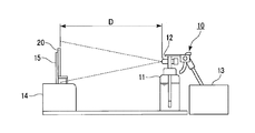
- FIG. 1 is a schematic diagram illustrating a spraying apparatus and a spraying method using the spraying apparatus.
- FIG. 2 is a schematic configuration diagram of an apparatus used for imaging and image analysis of the surface of the transparent member.
- the spraying device 10 includes a tank 11 that stores a contamination promoting liquid or tap water, a two-fluid nozzle 12 attached to the tank 11, and a compressor 13 that supplies air to the two-fluid nozzle 12.
- the transparent member 20 on which the contamination promoting liquid and tap water are sprayed is installed on the height adjusting table 14 by the fixing table 15 so as to be perpendicular to the horizontal plane.
- the distance between the surface of the transparent member 20 and the tip of the two-fluid nozzle 12 is 600 mm, the center in the spray direction of the contamination promoting liquid or tap water (the position of the tip of the two-fluid nozzle 12) and the center of the transparent member 20 Are consistent.
- An apparatus used for light irradiation on the surface of the transparent member, imaging of the surface, and image analysis is installed in a dark room, and includes a visual inspection light 31, a digital camera (imaging means) 32, a digital camera 32, and a transparent.
- the visual inspection light 31 is installed in the direction of the fixture 33 so as to irradiate light parallel to the horizontal plane.
- the digital camera 32 is fixed to the fixture 33 with the lens facing downward in the vertical direction (transparent member 20 side) with respect to the horizontal plane. Further, it is connected to a computer 34 so that photographed photograph data can be input to the computer 34.
- the irradiation direction of the light from the visual inspection light 31 is orthogonal to the direction in which the lens of the digital camera 32 is directed.
- the visual inspection light 31 is preferably capable of irradiating light having an illuminance of about 15000 to 25000 lux.
- An example of the digital camera 32 includes a camera having 15 million effective pixels or more and a sensor size APS-C. During the evaluation, the setting of the digital camera 32 is not changed.
- the fixture 33 is a rod-like instrument installed perpendicular to the horizontal plane, and includes a camera fixing portion at the upper portion and a transparent member fixing portion at a lower side thereof.
- the height of the transparent member fixing portion is substantially the same as the height of the visual inspection light 31.
- the transparent member fixing portion is configured to sandwich the transparent member 20 from the front surface side and the back surface side, and to adjust the angle of the surface of the transparent member 20 with respect to the irradiation direction of the light from the visual inspection light 31.
- the evaluation method using the apparatus shown in FIGS. 1 and 2 can be performed, for example, by the following procedure.
- Two spraying apparatuses 10 are prepared, and the contamination promoting liquid is stored in the tank 11 of one spraying apparatus 10, and tap water is stored in the tank 11 of the other spraying apparatus 10.
- the transparent member 20 is installed on the fixed table 15, and the fixed table 15 is installed on the table 14. Thereby, the transparent member 20 is installed perpendicularly
- the spraying device 10 containing the contamination promoting liquid is installed at a position facing the surface of the transparent member 20, and the contamination promoting liquid is sprayed from the position onto the surface of the transparent member 20 and dried.
- the spraying device 10 containing the contamination promoting liquid is replaced with the spraying device 10 containing tap water, and the tap water is sprayed on the surface of the transparent member 20 and dried.
- the above-described spraying and drying of the pollution promoting liquid and the spraying and drying of tap water are defined as one cycle, and two or more cycles are performed as necessary.
- the distance D between the surface of the transparent member 20 and the tip of the two-fluid nozzle 12 of the spraying device 10 is appropriately set so that the contamination promoting liquid and tap water are sprayed on the entire surface of the transparent member 20.
- the number of cycles is preferably 1 to 5 times, and particularly preferably 3 times in terms of efficiency.
- a luminance value distribution histogram is created in the following procedure before and after the above cycle.
- the transparent member 20 is directed to the fixture 33 in the dark room, the surface 20a is directed upward (to the digital camera 32 side), and the irradiation direction D1 of the light from the visual inspection light 31 and the surface 20a of the transparent member 20 are formed.
- the angle ⁇ 1 is fixed to a desired value.
- the angle ⁇ 1 is preferably ⁇ 5 to 30 °.
- FIG. 3 shows the arrangement of the transparent member 20 when the angle ⁇ 1 is a positive value.
- the light irradiation direction D1 is orthogonal to the direction D2 in which the lens of the digital camera 32 is directed.
- the horizontal axis represents the luminance value of 2 m gradation and the vertical axis represents A luminance value distribution histogram taking the ratio of the number of pixels is created.
- m is 6 to 20, and preferably 8 to 16. As m is larger, more detailed luminance value information can be obtained. It is preferable that m is 8 (256 gradations) or more in that the difference between the dirt and the base material is sufficiently discriminated.
- the evaluation method of the present invention is not limited to the above procedure.
- the imaging means is not limited to a digital camera, and may be a film camera or the like. Image processing software other than ImageJ may be used.
- transparent member (A) has a root mean square value (RMS value) ⁇ determined by the following method (I) of 40 or less.
- the following contamination promoting liquid is sprayed on the surface of the transparent member for 5 seconds using the following spraying device and dried at 60 ° C. for 1 hour, and then tap water is applied to the surface using the spraying device.
- the process of spraying for 180 seconds and drying at 60 ° C. for 1 hour is performed as 3 cycles for 3 cycles.
- the surface is irradiated with light having an illuminance of 20000 lux in the same procedure as above, and the surface is imaged to obtain image data of the surface, which is randomly extracted from the image data.
- Contamination promoting liquid 11 kinds of test powder 1 (Kanto loam, median diameter 1.6 to 2.3 ⁇ m) defined in JIS Z 8901 (2006) are dispersed in water at a concentration of 0.1% by mass. Dispersion.
- Spraying device A two-fluid nozzle spray gun installed at a position 600 mm away from the surface with a sprayed droplet size of 10 ⁇ m and a spray amount of 20 g / min.
- the RMS value ⁇ is calculated from the obtained x 0 and x i by the following equation (1).
- i in Formula (1) shows the ratio of the number of pixels, and takes an integer from 0 to 100 in increments of 1.
- n indicates the maximum value of the ratio of the number of pixels, and is 100.
- Method (I) can be carried out using the apparatus shown in FIGS.
- the smaller the RMS value ⁇ obtained by the above-mentioned equation (1) the closer the state of contamination is to the state before spraying the contamination promoting liquid. That is, the dirt is difficult to adhere or the attached dirt is easily removed by washing with water, rain, or the like. Therefore, the transparent member (A) is less likely to accumulate large conspicuous dirt on the surface outdoors, and the appearance and translucency are less likely to deteriorate even when placed outdoors for a long period of time. Also, the cleaning cost for removing dirt is low.
- the RMS value ⁇ can be adjusted by the hydrophilicity of the surface of the transparent member, the surface shape, and the like. For example, the RMS value ⁇ tends to be smaller when the surface of the transparent member is hydrophilic than when the surface of the transparent member is hydrophobic. When unevenness is formed on the surface of the transparent member, the RMS value ⁇ tends to be smaller than when no unevenness is formed. In the case where unevenness is formed on the surface, the RMS value ⁇ can be adjusted by the size of the unevenness, the interval between the plurality of protrusions or recesses, the shape of the unevenness, and the like.
- the transparent member (A) has a surface protrusion density of 0.1 to 100 ⁇ m ⁇ 2 , an arithmetic average surface roughness (Ra) of 2 to 60 nm, and a water contact angle of 0 to 10 °. More preferably, the protrusion density is 0.2 to 100 ⁇ ⁇ m ⁇ 2 , the arithmetic average surface roughness (Ra) is 2 to 50 nm, the water contact angle is 0 to 8 °, and the protrusion density is 0. in .4 ⁇ 100 ⁇ [mu] m -2, arithmetic average surface roughness (Ra) in the 2 ⁇ 45 nm, and further preferably water contact angle of 0 ⁇ 5 °. If the surface protrusion density, arithmetic average surface roughness, and water contact angle are within the above ranges, the RMS value ⁇ tends to be 40 or less.
- the transparent member (A) has a base material and a hydrophilic coating film provided on the base material, and there are irregularities on the surface of the portion where the hydrophilic coating film is provided.
- a transparent substrate hereinafter, also referred to as “transparent substrate (A1)” having an RMS value ⁇ of 40 or less is preferable. Examples of the substrate and the hydrophilic coating film include those shown in the first embodiment described later.
- a glass plate is preferable as the substrate.
- a glass plate having irregularities formed on the surface examples thereof include a method of forming a hydrophilic coating film thereon, and a method of forming by wet blasting, as shown in the method for producing a transparent member of the second aspect described later.
- a method of forming by wet blasting is preferable. If the unevenness is formed by wet blasting, the antifouling property is more excellent.
- the wet blast treatment is preferably performed so that the arithmetic average surface roughness (Ra) of the surface to be processed is 8.5 to 30 nm and the root mean square roughness (Rq) is 11 to 30 nm. More preferably, the arithmetic average surface roughness (Ra) of the surface is 8.5 to 25 nm and the root mean square roughness (Rq) is 11 to 25 nm.
- FIG. 4 is a cross-sectional view schematically showing the first embodiment of the transparent member (A).
- the transparent member 1 according to the first embodiment includes a base material 3 having an uneven surface and a hydrophilic coating film 5 formed on the surface of the base material 3.
- the RMS value ⁇ obtained by the method (I) of the transparent member 1 is 40 or less.
- the substrate 3 is not particularly limited as long as it is transparent. “Transparent” here is synonymous with “transparent” in the transparent member.
- Examples of the form of the substrate 3 include a plate and a film. In the case of a plate shape, it is not limited to a flat plate shape as illustrated, and the entire surface or a part thereof may have a curvature.
- Examples of the material of the base material 3 include glass and resin. Examples of the glass include soda lime glass, borosilicate glass, aluminosilicate glass, and alkali-free glass. Examples of the resin include polyethylene terephthalate, polycarbonate, triacetyl cellulose, polymethyl methacrylate, and the like.
- a glass plate is preferable in terms of excellent ultraviolet resistance (UV) resistance and heat resistance.
- the glass plate may be a glass plate having a curved surface as well as a flat glass plate.
- the glass plate may be a tempered glass plate such as a chemically tempered glass plate or an air-cooled tempered glass plate.
- Concavities and convexities are formed on the surface of the substrate 3 (surface on the hydrophilic coating film 5 side).
- the surface shape of the substrate 3 include a shape in which a plurality of convex portions and / or concave portions are randomly distributed, a shape in which a plurality of convex portions and / or concave portions are regularly arranged, and the like.
- the shape and size of the plurality of convex portions and / or concave portions may be the same or different.
- protrusion scattered, etc. are mentioned.
- the elongate groove channel extended on the surface of the base material 3, the hole scattered, etc.
- the shape of the ridge or groove include a straight line, a curved line, a bent shape, and the like.
- a plurality of ridges or grooves may exist in parallel to form a stripe shape.
- the cross-sectional shape of the ridges or grooves in the direction perpendicular to the longitudinal direction include polygons such as triangles (V-shaped), semicircles, and the like.
- Examples of the shape of the protrusion include a polygonal pyramid shape such as a triangular pyramid shape, a quadrangular pyramid shape, and a hexagonal pyramid shape, a conical shape, a hemispherical shape, a polyhedral shape, and other various indefinite shapes.
- Protrusion density of the surface of the substrate 3 is preferably 0.1 to 100 ⁇ [mu] m -2, more preferably 0.2 to 100 ⁇ [mu] m -2, more preferably 0.4 to 100 ⁇ [mu] m -2 . If the protrusion density on the surface of the substrate 3 is within the above range, the surface Ra of the hydrophilic coating film formed on the surface, that is, the protrusion density on the surface of the transparent member 1 tends to be within the range described later.
- the arithmetic average surface roughness (Ra) of the surface of the substrate 3 is preferably 2 to 60 nm, more preferably 2 to 50 nm, still more preferably 2 to 45 nm, particularly preferably 8.5 to 30 nm, and 8.5 to 25 nm. Is most preferred. If the Ra of the surface of the substrate 3 is within the above range, the Ra of the surface of the hydrophilic coating film formed on the surface, that is, the Ra of the surface of the transparent member 1 is likely to be within the range described later.
- the thickness of the substrate 3 is not particularly limited, but is preferably 0.3 to 15.0 mm, and more preferably 0.5 to 12.0 mm. If the thickness of the base material 3 is not less than the lower limit of the above range, the mechanical strength of the base material is excellent. If the thickness of the base material 3 is not more than the upper limit of the above range, the transmittance is excellent.
- the hydrophilic coating film 5 is provided to increase the hydrophilicity of the surface. Since the surface of the transparent member 1 is hydrophilic, hydrophobic dirt is difficult to adhere. Moreover, the dirt adhering to the surface is easily removed by rain, water washing or the like.
- Examples of the hydrophilic coating film 5 include a film formed from a hydrophilic coating agent.
- Examples of the material of the hydrophilic film to be formed include hydrophilic polymers and metal oxides such as silica and titania.
- Examples of the hydrophilic coating agent include solutions and dispersions of polymers having many hydrophilic groups, silica particle dispersions, titania particle dispersions, alkoxysilane partial hydrolysates solutions and dispersions, and the like.
- Commercially available hydrophilic coating agents include LAMBIC series hydrophilic coating agents manufactured by Osaka Organic Chemical Industry Co., Ltd., and ST-K series hydrophilic coating agents that are photocatalytic titanium oxide coating agents manufactured by Ishihara Sangyo Co., Ltd. .
- a hydrophilic polymer film is formed from the LAMBIC series hydrophilic coating agent, and a hydrophilic titanium oxide film is formed from the ST-K series hydrophilic coating agent.
- the thickness of the hydrophilic coating film 5 is preferably 0.01 to 1.00 ⁇ m, more preferably 0.02 to 0.20 ⁇ m. If the thickness of the hydrophilic coating film 5 is not less than the lower limit of the above range, the hydrophilicity is excellent. If the thickness of the base material 3 is not more than the upper limit of the above range, the visibility is excellent.
- the hydrophilic coating film 5 is formed on the surface of the base material 3 having irregularities formed on the surface, the surface of the hydrophilic coating film 5, that is, the surface of the transparent member 1 is the same as the surface of the base material 3. , There are irregularities.
- the protrusion density on the surface of the hydrophilic coating film 5 (the protrusion density on the surface of the transparent member 1) is preferably 0.1 to 100 pieces / ⁇ m ⁇ 2 , more preferably 0.2 to 100 pieces / ⁇ m ⁇ 2 , and 0 More preferably, 4 to 100 ⁇ ⁇ m ⁇ 2 .
- the RMS value ⁇ obtained by the method (I) tends to be 40 or less.
- the protrusion density on the surface of the transparent member 1 can be adjusted by the protrusion density on the surface of the substrate 3.
- the arithmetic average surface roughness (Ra) of the surface of the transparent member 1 is preferably 2 to 60 nm, more preferably 2 to 50 nm, and even more preferably 2 to 45 nm. If the Ra of the surface of the transparent member 1 is within the above range, the RMS value ⁇ obtained by the method (I) tends to be 40 or less.
- the Ra of the surface of the transparent member 1 can be adjusted by the Ra of the surface of the substrate 3.
- the water contact angle on the surface of the transparent member 1 is preferably 0 to 10 °, more preferably 0 to 8 °, and further preferably 0 to 5 °. If the water contact angle on the surface of the transparent member 1 is within the above range, the RMS value ⁇ obtained by the method (I) tends to be 40 or less.
- the water contact angle can be adjusted by the material forming the hydrophilic coating film 5, the surface shape of the substrate 3 (projection density, Ra, projection shape, etc.) and the like. Regarding the surface shape, for example, as the protrusion density increases, the water contact angle tends to increase. As Ra increases, the water contact angle tends to increase.
- FIG. 5 An example of the manufacturing method of the transparent member 1 is shown.
- the manufacturing method of this example includes the following steps ( ⁇ 1) to ( ⁇ 7).
- ( ⁇ 1) A water-repellent coating agent is applied to the surface of the glass plate 3A to form a water-repellent coating film 7A (FIG. 5A).
- ( ⁇ 2) Wax is deposited on the water repellent coating film 7A. The wax is repelled by the water-repellent coating film 7A and agglomerates into fine particles to form island-shaped wax portions 9A (FIG. 5B).
- a laminate including a glass plate 3B having irregularities formed on the surface, a water repellent pattern film 7B that covers the protrusions on the surface of the glass plate 3B, and a wax portion 9A that covers the water repellent pattern film 7B is obtained.
- FIG. 5D The wax portion 9A of the laminate is removed (FIG. 5 (e)).
- the water-repellent pattern film 7B is removed by plasma etching (FIG. 5F).
- a hydrophilic coating agent is applied to the surface of the glass plate 3B to form the hydrophilic coating film 5 (FIG. 5G). Thereby, the transparent member 1 provided with the glass plate 3B as the base material 3 is obtained.
- the glass plate 3A may be a smooth glass plate formed by a float method, a fusion method, a downdraw method, or the like, or may be a template glass. Moreover, not only a flat glass plate but the glass plate which has a curved surface may be sufficient.
- the glass plate 3A may be a tempered glass plate.
- water repellent coating agent examples include fluorine paint and silicone oil.
- water-repellent coating agents examples include OPTOOL (registered trademark) series manufactured by Daikin and Unidyne series manufactured by Daikin.
- the application of the water repellent coating agent may be performed by a wet coating method or a dry coating method.
- the wet coating method include a roll coating method, a casting method, a dip coating method (dipping method), a spin coating method, a water casting method, a die coating method, and a Langmuir / Projet method.
- the dry coating method include a vacuum deposition method, a CVD method, and a sputtering method.
- the hydrophilic coating agent may be applied by a wet coating method or a dry coating method.
- a dip coating method is preferable.
- the protrusion density on the surface of the glass plate 3B, and thus the protrusion density on the surface of the transparent member 1 can be adjusted by the wax deposition time.
- the Ra on the surface of the glass plate 3B, and thus the Ra on the surface of the transparent member 1, can be adjusted by the etching time in the step ( ⁇ 4).
- the transparent member (A) has been described with reference to the first embodiment, but the present invention is not limited to the above embodiment.
- the transparent member 1 of the first embodiment may further include a layer other than the base material 3 and the hydrophilic coating film 5.
- the transparent member 1 of the first embodiment may further include a layer other than the base material 3 and the hydrophilic coating film 5.
- other layers include an undercoat layer, a stress relaxation layer, an adhesion improving layer, and a protective layer.
- the undercoat layer has a function as an alkali barrier layer or a wide band low refractive index layer when the substrate 3 is made of glass.
- the transparent member of the present invention may be composed of only the base material 3 as long as it has a desired RMS value ⁇ .
- the method for producing the transparent member of the present invention is not limited to the above example.
- it may be produced by the method for producing a transparent member of the present invention described later, and in addition, a particle dispersant may be added on the substrate instead of the steps ( ⁇ 1) to ( ⁇ 6) in the production method shown in the first embodiment.
- a particle dispersant may be added on the substrate instead of the steps ( ⁇ 1) to ( ⁇ 6) in the production method shown in the first embodiment.
- examples thereof include a coating method and a method in which the substrate surface is wet-etched with hydrofluoric acid or the like.
- the surface protrusion density, arithmetic average surface roughness (Ra), water contact angle, and the like can be adjusted according to the material of the particle dispersant, particle diameter, coating conditions (coating amount, etc.) and the like.
- the transparent member of the second aspect of the present invention (hereinafter also referred to as “transparent member (B)”) has a surface with unevenness, and the arithmetic average surface roughness (Ra) of the surface with the unevenness. Is 8.5 to 30 nm, and the root mean square roughness (Rq) is 11 to 30 nm.
- the arithmetic average surface roughness (Ra) is preferably 8.5 to 25 nm.
- the root mean square roughness (Rq) is preferably 11 to 25 nm.
- the transparent member (B) for example, a glass plate having a hydrophilic coating film on the surface (hereinafter also referred to as a precursor) obtained by subjecting the surface of the hydrophilic coating film to a wet blast treatment described later ( Hereinafter, it is also referred to as “transparent member (B1)”.
- the surface on which the unevenness exists may be a surface having the RMS value ⁇ of 40 or less, or may not be a surface having the RMS value ⁇ of 40 or less. It is preferable that the surface has an RMS value ⁇ of 40 or less.
- a transparent member (B1) can be manufactured with the manufacturing method of the transparent member of this invention mentioned later.
- the method for producing the transparent member (B) may be any method that can form a surface having an arithmetic average surface roughness (Ra) of 8.5 to 30 nm and a root mean square roughness (Rq) of 11 to 30 nm. It is not limited to the above example.
- the method for producing a transparent member of the present invention is characterized in that the hydrophilic coating film surface of the precursor is subjected to the following wet blast treatment (hereinafter also referred to as “step (i)”).
- Wet blasting A liquid in which particles are dispersed is sprayed on the surface of the hydrophilic coating film, whereby the arithmetic average surface roughness (Ra) is 8.5 to 30 nm and the root mean square roughness (Rq) on the hydrophilic coating film surface. Is a process for forming irregularities of 11 to 30 nm.
- the transparent member precursor examples of the glass plate and the hydrophilic coating film are the same as those described in the description of the transparent member (A1).
- the surface of the glass plate may or may not be uneven.
- the precursor can be obtained, for example, by applying a hydrophilic coating agent to the surface of the glass plate to form a hydrophilic coating film as in the step ( ⁇ 7). If what has a glass plate and the hydrophilic coating film formed on the said glass plate is marketed, this may be used as a precursor.
- the surface to be treated before wet blasting typically has an arithmetic average surface roughness (Ra) of less than 8.5 nm and a root mean square roughness. (Rq) is less than 10 nm.
- the wet blast treatment is performed on the precursor with the surface of the portion provided with the hydrophilic coating film as the surface to be treated.
- irregularities are formed on the surface to be treated.
- the transparent member which has a glass plate and the hydrophilic coating film formed on the said glass plate, and an unevenness
- the wet blast treatment smaller particles can be used and finer irregularities can be formed as compared with the dry blast treatment in which only the particles are sprayed on the surface to be treated.
- the wet blast treatment is performed so that the arithmetic average surface roughness (Ra) of the treated surface after the wet blast treatment is 8.5 to 30 nm and the root mean square roughness (Rq) is 11 to 30 nm.
- the wet blast treatment is preferably performed so that the surface to be treated has an arithmetic average surface roughness (Ra) of 8.5 to 25 nm and a root mean square roughness (Rq) of 11 to 25 nm.
- the arithmetic average surface roughness (Ra) and the root mean square roughness (Rq) are within the above ranges, the antifouling property of the surface to be processed is improved.
- the RMS value ⁇ obtained by the method (I) tends to be 40 or less.
- the transparent member obtained in this way is a transparent member obtained by forming a hydrophilic coating film on a glass plate having irregularities formed on the surface as in the manufacturing method shown in the first embodiment. Compared to the above, when exposed to the outdoors and visually evaluated for dirt, the dirt looks less and the antifouling property is better. Arithmetic average surface roughness (Ra) and root mean square roughness (Rq) of the surface to be processed can be adjusted by wet blasting conditions (particle type, spraying conditions, etc.).
- the particle size of the particles in the slurry used for the wet blast treatment is preferably 0.1 to 250 ⁇ m, more preferably 0.5 to 100 ⁇ m.
- the particle diameter is not less than the lower limit of the above range, a good treatment speed can be obtained.
- the particle diameter is not more than the upper limit of the above range, a fine uneven shape suitable for antifouling performance can be obtained.
- the particles preferably have a Vickers hardness equal to or higher than that of the surface to be processed.
- the processing speed is excellent.
- the Vickers hardness of the particles can be adjusted by the material of the particles, thermal, chemical treatment, and the like.
- the shape of the particles is preferably non-spherical. If it is non-spherical, fine irregularities can be efficiently formed on the surface to be treated. Also, a good processing speed can be obtained.
- the material of the particles is not particularly limited, and examples thereof include iron, stainless steel, aluminum, zinc, copper, silicon oxide, aluminum oxide, silicon carbide, glass, plastic, and rubber.
- the number of particles contained in the slurry may be one, or two or more.
- the above-mentioned contamination promoting liquid can also be used.
- Kanto Loam is composed of fine powder of volcanic ash composed mainly of silicon oxide, aluminum oxide and iron oxide.
- the particle diameter of the particles in the Kanto Loam slurry used as the contamination promoting liquid is 1.6 to 2.3 ⁇ m, and the concentration thereof is 0.1% by mass.
- a slurry having a higher concentration than the contamination promoting liquid, a slurry having a different particle diameter from Kanto Loam, etc. can be used.
- the content (solid content concentration) of particles in the slurry is preferably 0.01 to 50% by mass, more preferably 0.1 to 30% by mass, based on the total amount of the slurry.
- the content of the particles in the slurry is not less than the lower limit of the above range, a good processing speed can be obtained. If the content of the particles is not more than the upper limit of the above range, the particles do not settle and stable treatment is possible.
- the liquid (dispersion medium) in which the particles are dispersed in the slurry is not particularly limited as long as the liquid has good particle dispersibility and low reactivity to these components, but the following are preferable.
- Alcohol methanol, ethanol, 2-propanol, etc.
- ester acetic ester (butyl acetate), etc.
- ether diethylene glycol dimethyl ether, etc.
- ketone methyl ethyl ketone, etc.
- water ion-exchanged water, etc.
- glycol ethylene glycol, glycerol, etc.
- the slurry may contain components other than the particles.
- components other than the particles include acids, alkalis, inorganic salts, silicone, desalted water glass, and hydrolyzed alkoxysilanes.
- Spraying of the slurry onto the surface to be treated can be performed using a known wet blasting apparatus. For example, it can be performed using an apparatus similar to the spraying apparatus 10 shown in FIG.
- requiring RMS value (sigma) by method (I) is corresponded to the said slurry, since the spray amount is as small as 20 g / min, an unevenness
- the slurry concentration is set higher than 0.1% by mass (for example, 1% by mass), and the particle size of the sprayed droplets is 10 ⁇ m.
- the surface to be processed can be wet blasted by changing the conditions such as increasing the spray amount to an amount exceeding 20 g / min, or setting the distance between the nozzle of the spray gun and the non-processed surface to less than 600 mm. .
- the conditions for spraying the slurry onto the surface to be treated are set such that the arithmetic average surface roughness (Ra) and the root mean square roughness (Rq) are within desired ranges.
- the flow rate of the slurry is preferably 10 to 1000 m / second, more preferably 50 to 500 m / second. When the flow rate is not less than the lower limit of the above range, a good processing speed can be obtained. When the flow rate is less than or equal to the upper limit of the above range, the uniformity of the concavo-convex shape is excellent, and breakage of the glass plate can be prevented.
- the treatment time is preferably 0.1 to 300 seconds / cm 2 , more preferably 1.0 to 100 seconds / cm 2 .
- the distance between the surface to be treated and the tip of the nozzle from which the slurry is jetted is preferably 0.1 to 100.0 cm, and more preferably 1 to 50.0 cm.
- the glass plate can be prevented from being damaged.
- the utilization efficiency of the slurry is excellent.
- examples 1 to 13 described later examples 2 to 5 and 7 to 13 are examples, and examples 1 and 6 are comparative examples.
- the measurement method used in each example is shown below.
- the water contact angle was measured using a contact angle meter (manufactured by Kyowa Interface Chemical Co., Ltd., DropMaster 500) with the droplet size set to 20 ⁇ L. The measurement was performed in an atmosphere at a temperature of 20 to 22 ° C. and a relative humidity of 20 to 50%.
- Ra Arimetic mean surface roughness (Ra), root mean square roughness (Rq) measurement method
- AFM Nanoscope IIIa manufactured by Bruker AXS
- the three-dimensional surface shape is obtained by AFM.
- the data was measured, and Ra was calculated from the following formula (2) and Rq was calculated from the following formula (3) from the obtained three-dimensional data.
- A is an area when the designated surface is assumed to be ideally flat, and is 10 ⁇ m ⁇ 10 ⁇ m here.
- Z (x, y) represents the roughness curve of the substrate.
- Z 2 (x, y) represents a value obtained by squaring the roughness curve of the substrate.
- Protrusion density is measured per unit area when an uneven shape of 10 ⁇ m ⁇ 10 ⁇ m is measured by AFM, and a protrusion having a height of 2 nm or more adjacent to the convex portion is defined as a protrusion. The number of protrusions was calculated.
- Example 1 to Example 6 (Production of transparent member)
- the transparent members of Examples 1 to 6 were produced in the following procedure and only by changing the time for immersion in the etching solution.
- the surface of a glass plate (manufactured by Asahi Glass Co., Ltd., soda lime glass, 50 mm ⁇ 100 mm, thickness 0.7 mm) was washed with methanol, and a water repellent (Optool DSX, manufactured by Daikin) was immersed on the surface for 3 minutes. Dip coating was performed at a lifting speed of 2 mm / sec. Thereafter, a water-repellent coating film was formed by performing heat treatment at 100 ° C.
- the glass plate was etched with a plasma etching apparatus (YHS-R, manufactured by Sakai Semiconductor Co., Ltd.) for 10 seconds to remove the water-repellent coating film on the portion where no wax was adhered.
- a plasma etching apparatus YHS-R, manufactured by Sakai Semiconductor Co., Ltd.
- the surface of the glass plate was immersed in an etching solution containing hydrofluoric acid (manufactured by Flosstec Co., Ltd., glass etchant clear type SW-CL4N) for a predetermined time, and the glass on the portion where no wax or the like was adhered was etched.
- Example 1 is an example which was not immersed in the etching solution.
- the glass plate was washed with distilled water at 98 ° C.
- a hydrophilic coating agent (LAMBIC771W manufactured by Osaka Organic Chemical Industry Co., Ltd.) was dip coated on the surface of the glass plate at a dipping time of 5 minutes and a lifting speed of 6 mm / second to form a hydrophilic coating film.
- LAMBIC771W manufactured by Osaka Organic Chemical Industry Co., Ltd.
- the antifouling properties of the transparent members of Examples 1 to 6 were evaluated by the method (I) using an apparatus having the configuration shown in FIGS.
- a visual light a Power-Eye II LSP70 ⁇ 156W manufactured by ITEC System is used, and as an imaging device, a digital camera (EOS Kiss X5 [EF-S 18-55 ISII] manufactured by Canon Inc.) is used. Image data.
- ImageJ was used as image processing software.
- two fog spray guns YSG-05 (droplet particle size: 10 ⁇ m, spray amount: 20 g / min) manufactured by IAC Co., Ltd. are prepared as spraying devices, and one of them contains a contamination promoting liquid.
- tap water was accommodated.
- a spraying device containing the contamination promoting liquid is installed at a position 600 mm away from the surface of the transparent member, and the contamination promoting liquid is sprayed on the surface for 5 seconds using the spraying device, dried at 60 ° C. for 1 hour, and then The spraying device is replaced with one containing tap water, and using the spraying device, tap water is sprayed on the surface for 180 seconds and dried at 60 ° C. for 1 hour, 3 cycles are carried out as one cycle, RMS The value ⁇ was determined.
- Table 1 shows etching time, water contact angle, Ra, protrusion density, and RMS value ⁇ using the etching solution containing hydrofluoric acid in Examples 1 to 6.
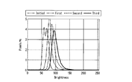
- the luminance value distribution histograms obtained in Example 2 were approximated by the least square method and converted into luminance value distribution curves, which were combined into one graph.
- the graph is shown in FIG.
- “Initial” corresponds to the luminance value distribution histogram obtained before spraying the contamination promoting liquid
- “First”, “Second”, and “Third” are 1 cycle, 2 cycles, and 3 cycles, respectively. It is a luminance value distribution curve corresponding to the luminance value distribution histogram obtained later.
- Ra When the etching time was 10 to 30 seconds, Ra was 10 to 50 nm, and when it was 0 seconds or 40 seconds or more, it was less than 10 nm.
- the reason why Ra is reduced when the etching time is 40 seconds or longer is considered to be that the portion masked with wax is also etched, and the height of the protrusion is reduced. Note that the difference in Ra when the etching time is 10 seconds, 20 seconds, and 30 seconds is considered to be due to the influence of variations in the deposited wax rather than the etching time.
- the transparent member of Example 2 had the smallest ratio of bright spots having high luminance values in the luminance value distribution measured after three cycles. Also, the dispersion was a small distribution. The value of ⁇ shown in Table 1 was also the smallest value for the transparent member of Example 2.
- Examples 7 to 13 (Preparation of desalted sodium silicate solution) While stirring 237.5 g of distilled water, sodium silicate 4 (manufactured by Nippon Chemical Industry Co., Ltd., SiO 2 : 24.0 mass%, Na 2 O: 7.0 mass%. SiO 2 / Na 2 O 62.5 g of a molar ratio of 3.5 / 1) and 180 g of cation exchange resin (Diaion SK1BH, manufactured by Mitsubishi Chemical Corporation) were added in this order, and the mixture was stirred for 10 minutes or more and then cation exchange resin by suction filtration. And a desalted sodium silicate solution having a solid content concentration of 5% by mass in terms of silicon oxide was obtained.
- sodium silicate 4 manufactured by Nippon Chemical Industry Co., Ltd., SiO 2 : 24.0 mass%, Na 2 O: 7.0 mass%.
- 180 g of cation exchange resin
- TiO 2 film forming composition (Preparation of TiO 2 film forming composition) While stirring 5.32 g of 2-propanol, 1.85 g of the titania particle dispersion (STK-01, manufactured by Ishihara Sangyo Co., Ltd.) and 2.18 g of the desalted sodium silicate solution were added in this order.
- a forming composition was prepared.
- a soda lime glass plate (manufactured by Asahi Glass Co., Ltd., product number FL3.5, length 100 mm, width 100 mm, thickness 3.5 mm) was set on a spin coater, and the TiO 2 film forming composition was placed on the soda lime glass plate. 2.0 g of the solution was dropped onto the surface of the substrate, spin-coated, and then baked at 300 ° C. for 30 minutes to produce a glass plate (precursor) with a TiO 2 film.
- FIG. 1 Manufacture of transparent substrate
- a micro fog spray gun YSG-05 nozzle diameter 0.5 ⁇ m
- ICC micro fog spray gun
- Slurry A dispersion in which 11 kinds of test powders 1 (Kanto loam, median diameter 1.6 to 2.3 ⁇ m) defined in JIS Z 8901: 2006 are dispersed in water at a concentration of 1% by mass.
- the TiO 2 film-coated glass plate to setting the base towards the surface of the TiO 2 film side to the spray device.
- Wet blasting is performed by spraying the slurry from a position 20 mm away from the surface while moving the spraying device carefully so that there is no gap in the center of the TiO 2 film-coated glass plate of 35 mm ⁇ 30 mm. It was.
- the spraying is performed from a position 20 mm away from the surface of the TiO 2 film, the compressor pressure is 0.4 MPa, the slurry flow rate is 318 m / second, the slurry spraying time (blast time) is 15 seconds, 30 seconds, 60 seconds, 180 seconds. For 480 seconds or 720 seconds.
- the blast time of 15 to 720 seconds in this example is 1.4 to 68.6 seconds / cm 2 as the processing time per unit area.
- FIG. 7 is a graph in which the horizontal axis represents the blast time (unit: seconds) of the wet blast treatment, and the vertical axis represents the measured values (unit: nm) of Ra and Rq.
- Example 7 the antifouling property was evaluated for the transparent members of Example 7 and Example 9 by the same procedure as Example 1.
- the results (RMS value ⁇ ) are shown in Table 2.
- FIG. 8 is a photograph of the transparent substrate of Example 9 after the outdoor exposure test
- FIG. 9 is a photograph of the soda lime glass plate after the outdoor exposure test.
- the area within the square near the center is a portion subjected to wet blasting, and the outside is a portion not subjected to wet blasting.
Landscapes
- Chemical & Material Sciences (AREA)
- Life Sciences & Earth Sciences (AREA)
- Engineering & Computer Science (AREA)
- Chemical Kinetics & Catalysis (AREA)
- General Chemical & Material Sciences (AREA)
- Geochemistry & Mineralogy (AREA)
- Materials Engineering (AREA)
- Organic Chemistry (AREA)
- General Physics & Mathematics (AREA)
- Physics & Mathematics (AREA)
- Health & Medical Sciences (AREA)
- Analytical Chemistry (AREA)
- Biochemistry (AREA)
- General Health & Medical Sciences (AREA)
- Mechanical Engineering (AREA)
- Immunology (AREA)
- Pathology (AREA)
- Surface Treatment Of Glass (AREA)
- Investigating Materials By The Use Of Optical Means Adapted For Particular Applications (AREA)
- Application Of Or Painting With Fluid Materials (AREA)
Abstract
L'invention concerne un élément transparent qui présente une excellente résistance aux taches. Cet élément transparent présente une surface dont la valeur moyenne quadratique σ déterminée conformément à la formule (1) est d'au maximum 40. [Dans la formule (1) : lorsque la surface de l'élément transparent est soumise à un traitement comprenant des procédures prédéfinies dans 3 cycles et, avant le début du traitement et après l'achèvement de chaque cycle, la surface est soumise à un rayonnement de lumière, l'image de la surface est captée à des fins d'acquisition de données d'images et un histogramme de distribution de valeurs de luminance est formé sur la base de ces données d'image, x0 représente une valeur de luminance au niveau de laquelle la proportion du nombre de pixels de l'élément transparent atteint le maximum dans l'histogramme de distribution de valeurs de luminance qui est obtenu au début du traitement ; xi représente une valeur de luminance correspondant à la proportion du nombre de pixels dans l'histogramme de distribution de valeurs de luminance qui est obtenu après l'achèvement des 3 cycles ; i représente la proportion du nombre de pixels qui est un entier compris entre 0 et 100 ; et n représente la valeur maximale de la proportion du nombre de pixels qui est 100].
Priority Applications (2)
| Application Number | Priority Date | Filing Date | Title |
|---|---|---|---|
| JP2016554101A JPWO2016060165A1 (ja) | 2014-10-17 | 2015-10-14 | 透明部材、透明部材の製造方法および透明部材の表面の汚れ具合の評価方法 |
| CN201580056061.2A CN107074627A (zh) | 2014-10-17 | 2015-10-14 | 透明部件、透明部件的制造方法以及透明部件的表面的污染情况的评价方法 |
Applications Claiming Priority (4)
| Application Number | Priority Date | Filing Date | Title |
|---|---|---|---|
| JP2014-212923 | 2014-10-17 | ||
| JP2014212923 | 2014-10-17 | ||
| JP2015051337 | 2015-03-13 | ||
| JP2015-051337 | 2015-03-13 |
Publications (1)
| Publication Number | Publication Date |
|---|---|
| WO2016060165A1 true WO2016060165A1 (fr) | 2016-04-21 |
Family
ID=55746707
Family Applications (1)
| Application Number | Title | Priority Date | Filing Date |
|---|---|---|---|
| PCT/JP2015/079059 WO2016060165A1 (fr) | 2014-10-17 | 2015-10-14 | Élément transparent, son procédé de fabrication et procédé d'évaluation du degré de salissure de la surface de cet élément transparent |
Country Status (3)
| Country | Link |
|---|---|
| JP (1) | JPWO2016060165A1 (fr) |
| CN (1) | CN107074627A (fr) |
| WO (1) | WO2016060165A1 (fr) |
Cited By (2)
| Publication number | Priority date | Publication date | Assignee | Title |
|---|---|---|---|---|
| JP2017090380A (ja) * | 2015-11-16 | 2017-05-25 | 株式会社デンソーウェーブ | レーザレーダ装置、レーザレーダ装置用の窓部材、及びレーザレーダ装置用の制御プログラム |
| KR20200027291A (ko) * | 2018-09-04 | 2020-03-12 | 주식회사 노바 | 연료전지 스택용 분리판의 친수성 검사장치 |
Families Citing this family (3)
| Publication number | Priority date | Publication date | Assignee | Title |
|---|---|---|---|---|
| DE102018102828B4 (de) * | 2018-02-08 | 2020-03-12 | Scansonic Mi Gmbh | Verfahren zur Überwachung eines Schutzglases |
| CN109001231A (zh) * | 2018-10-15 | 2018-12-14 | 芜湖东旭光电装备技术有限公司 | 一种表面缺陷检测设备 |
| CN110297562B (zh) * | 2019-06-27 | 2021-01-05 | 厦门天马微电子有限公司 | 显示驱动方法、显示面板和显示装置 |
Citations (14)
| Publication number | Priority date | Publication date | Assignee | Title |
|---|---|---|---|---|
| JPH0558677A (ja) * | 1991-08-30 | 1993-03-09 | Central Glass Co Ltd | 基材表面への微細凹凸形成法 |
| JPH10231146A (ja) * | 1996-12-18 | 1998-09-02 | Nippon Ita Glass Techno Res Kk | 防曇防汚ガラス物品 |
| JPH11100234A (ja) * | 1996-12-09 | 1999-04-13 | Nippon Sheet Glass Co Ltd | 防曇物品及びその製造方法 |
| JPH11512337A (ja) * | 1995-09-15 | 1999-10-26 | サン−ゴバン ビトラージュ | 光触媒コーティングを備えた基材 |
| JP2000239047A (ja) * | 1998-12-03 | 2000-09-05 | Nippon Sheet Glass Co Ltd | 親水性光触媒部材 |
| JP2001007363A (ja) * | 1999-06-18 | 2001-01-12 | Nippon Sheet Glass Co Ltd | 太陽電池用透明電極付きガラス |
| WO2003010525A1 (fr) * | 2001-07-27 | 2003-02-06 | Nippon Sheet Glass Co., Ltd. | Procede d'evaluation de la contamination superficielle d'un objet et dispositif imageur utilise a cet effet |
| JP2003075367A (ja) * | 2001-09-07 | 2003-03-12 | Central Glass Co Ltd | 透明板状体の欠点検出装置 |
| WO2004051724A1 (fr) * | 2002-12-03 | 2004-06-17 | Shin-Etsu Quartz Products Co., Ltd. | Montage en verre de silice utilise pour la fabrication de semi-conducteurs et fabrication dudit montage |
| JP2004341070A (ja) * | 2003-05-13 | 2004-12-02 | Fuji Photo Film Co Ltd | 防眩性フィルム及びその製造方法、反射防止フィルム、偏光板、画像表示装置 |
| JP2005528313A (ja) * | 2002-04-17 | 2005-09-22 | サン−ゴバン グラス フランス | 自己浄化性コーティングを有する基材 |
| WO2008029946A1 (fr) * | 2006-09-08 | 2008-03-13 | Dai Nippon Printing Co., Ltd. | Procédé et dispositif d'évaluation de contamination, procédé de fabrication de membre optique, corps optique multicouche et écran d'affichage |
| JP2008119924A (ja) * | 2006-11-10 | 2008-05-29 | Asahi Glass Co Ltd | 撥水性表面を有する物品 |
| JP2011164062A (ja) * | 2010-02-15 | 2011-08-25 | Ricoh Co Ltd | 透明平板検出システム |
Family Cites Families (2)
| Publication number | Priority date | Publication date | Assignee | Title |
|---|---|---|---|---|
| DE69734921T2 (de) * | 1996-12-09 | 2006-09-28 | Nippon Sheet Glass Co., Ltd. | Antibeschlag-gegenstand und dessen herstellungsverfahren |
| JP4118086B2 (ja) * | 2002-05-31 | 2008-07-16 | トヨタ自動車株式会社 | 親水性を有する防曇防汚性薄膜の製造方法 |
-
2015
- 2015-10-14 WO PCT/JP2015/079059 patent/WO2016060165A1/fr active Application Filing
- 2015-10-14 JP JP2016554101A patent/JPWO2016060165A1/ja active Pending
- 2015-10-14 CN CN201580056061.2A patent/CN107074627A/zh active Pending
Patent Citations (14)
| Publication number | Priority date | Publication date | Assignee | Title |
|---|---|---|---|---|
| JPH0558677A (ja) * | 1991-08-30 | 1993-03-09 | Central Glass Co Ltd | 基材表面への微細凹凸形成法 |
| JPH11512337A (ja) * | 1995-09-15 | 1999-10-26 | サン−ゴバン ビトラージュ | 光触媒コーティングを備えた基材 |
| JPH11100234A (ja) * | 1996-12-09 | 1999-04-13 | Nippon Sheet Glass Co Ltd | 防曇物品及びその製造方法 |
| JPH10231146A (ja) * | 1996-12-18 | 1998-09-02 | Nippon Ita Glass Techno Res Kk | 防曇防汚ガラス物品 |
| JP2000239047A (ja) * | 1998-12-03 | 2000-09-05 | Nippon Sheet Glass Co Ltd | 親水性光触媒部材 |
| JP2001007363A (ja) * | 1999-06-18 | 2001-01-12 | Nippon Sheet Glass Co Ltd | 太陽電池用透明電極付きガラス |
| WO2003010525A1 (fr) * | 2001-07-27 | 2003-02-06 | Nippon Sheet Glass Co., Ltd. | Procede d'evaluation de la contamination superficielle d'un objet et dispositif imageur utilise a cet effet |
| JP2003075367A (ja) * | 2001-09-07 | 2003-03-12 | Central Glass Co Ltd | 透明板状体の欠点検出装置 |
| JP2005528313A (ja) * | 2002-04-17 | 2005-09-22 | サン−ゴバン グラス フランス | 自己浄化性コーティングを有する基材 |
| WO2004051724A1 (fr) * | 2002-12-03 | 2004-06-17 | Shin-Etsu Quartz Products Co., Ltd. | Montage en verre de silice utilise pour la fabrication de semi-conducteurs et fabrication dudit montage |
| JP2004341070A (ja) * | 2003-05-13 | 2004-12-02 | Fuji Photo Film Co Ltd | 防眩性フィルム及びその製造方法、反射防止フィルム、偏光板、画像表示装置 |
| WO2008029946A1 (fr) * | 2006-09-08 | 2008-03-13 | Dai Nippon Printing Co., Ltd. | Procédé et dispositif d'évaluation de contamination, procédé de fabrication de membre optique, corps optique multicouche et écran d'affichage |
| JP2008119924A (ja) * | 2006-11-10 | 2008-05-29 | Asahi Glass Co Ltd | 撥水性表面を有する物品 |
| JP2011164062A (ja) * | 2010-02-15 | 2011-08-25 | Ricoh Co Ltd | 透明平板検出システム |
Cited By (3)
| Publication number | Priority date | Publication date | Assignee | Title |
|---|---|---|---|---|
| JP2017090380A (ja) * | 2015-11-16 | 2017-05-25 | 株式会社デンソーウェーブ | レーザレーダ装置、レーザレーダ装置用の窓部材、及びレーザレーダ装置用の制御プログラム |
| KR20200027291A (ko) * | 2018-09-04 | 2020-03-12 | 주식회사 노바 | 연료전지 스택용 분리판의 친수성 검사장치 |
| KR102121198B1 (ko) | 2018-09-04 | 2020-06-10 | 주식회사 노바 | 연료전지 스택용 분리판의 친수성 검사장치 |
Also Published As
| Publication number | Publication date |
|---|---|
| JPWO2016060165A1 (ja) | 2017-08-03 |
| CN107074627A (zh) | 2017-08-18 |
Similar Documents
| Publication | Publication Date | Title |
|---|---|---|
| WO2016060165A1 (fr) | Élément transparent, son procédé de fabrication et procédé d'évaluation du degré de salissure de la surface de cet élément transparent | |
| JP6939573B2 (ja) | 透光性構造体 | |
| JP3786365B2 (ja) | 親水性表面を備えた部材 | |
| US20140308529A1 (en) | Coating Composition And Antireflective Coating Prepared Therefrom | |
| JP6989650B2 (ja) | 低反射コーティング付ガラス基板、低反射コーティング付ガラス基板を製造する方法、及び光電変換装置 | |
| CN113891866B (zh) | 纹理化玻璃制品及其制造方法 | |
| JP6826985B2 (ja) | コーティング膜付きガラス板及びその製造方法 | |
| KR20160012186A (ko) | 유리 캐리어를 갖는 얇은 플렉서블 유리 기판을 가공하는 방법 | |
| JP6805127B2 (ja) | コーティング膜付きガラス板及びその製造方法 | |
| WO2012165107A1 (fr) | Substrat résistant aux taches de type empreintes digitales | |
| JP2017177683A (ja) | 撥水性被膜付基材およびその製造方法 | |
| WO2016010080A1 (fr) | Article antisalissure, son procédé de production, composition formant couche antisalissure et verre de couverture pour cellules solaires | |
| TW201816426A (zh) | 防眩構件之製造方法 | |
| WO2023026971A1 (fr) | Élément en verre hydrofuge et son procédé de fabrication, élément de lentille, élément de couverture et élément de panneau fenêtre | |
| JP4292992B2 (ja) | 光触媒膜形成用組成物および光触媒膜付き基材 | |
| JPH10180948A (ja) | 転写シ−ト、及び光触媒性親水性薄膜の転写方法 | |
| JPH1067543A (ja) | 光触媒性親水性部材 | |
| JP2017001000A (ja) | 撥水性面形成方法及びその方法を用いて形成された撥水性面を備えた撥水性物品 | |
| JP2006070141A (ja) | 光触媒膜形成用組成物および光触媒膜付き基材 | |
| KR20220066001A (ko) | 효율적이고 확장 가능한 자가 세정 코팅을 제조하기 위한 방법 | |
| TW202104938A (zh) | 覆蓋玻璃以及數位看板 | |
| JPWO2020071202A1 (ja) | 車両用窓ガラス、及びその製造方法 | |
| JPH1121511A (ja) | 光触媒性親水性部材、及び光触媒性親水性塗料組成物 | |
| JPH10297940A (ja) | 親水性被膜の形成方法 | |
| TW201323546A (zh) | 塗料組合物以及由其製備之減反射塗層 |
Legal Events
| Date | Code | Title | Description |
|---|---|---|---|
| 121 | Ep: the epo has been informed by wipo that ep was designated in this application |
Ref document number: 15850804 Country of ref document: EP Kind code of ref document: A1 |
|
| ENP | Entry into the national phase |
Ref document number: 2016554101 Country of ref document: JP Kind code of ref document: A |
|
| NENP | Non-entry into the national phase |
Ref country code: DE |
|
| 122 | Ep: pct application non-entry in european phase |
Ref document number: 15850804 Country of ref document: EP Kind code of ref document: A1 |