WO2016039256A1 - 表示機能付きミラー装置および表示切替方法 - Google Patents
表示機能付きミラー装置および表示切替方法 Download PDFInfo
- Publication number
- WO2016039256A1 WO2016039256A1 PCT/JP2015/075121 JP2015075121W WO2016039256A1 WO 2016039256 A1 WO2016039256 A1 WO 2016039256A1 JP 2015075121 W JP2015075121 W JP 2015075121W WO 2016039256 A1 WO2016039256 A1 WO 2016039256A1
- Authority
- WO
- WIPO (PCT)
- Prior art keywords
- display
- mirror
- motion
- function
- display function
- Prior art date
- Legal status (The legal status is an assumption and is not a legal conclusion. Google has not performed a legal analysis and makes no representation as to the accuracy of the status listed.)
- Ceased
Links
Images


Classifications
-
- B—PERFORMING OPERATIONS; TRANSPORTING
- B60—VEHICLES IN GENERAL
- B60R—VEHICLES, VEHICLE FITTINGS, OR VEHICLE PARTS, NOT OTHERWISE PROVIDED FOR
- B60R1/00—Optical viewing arrangements; Real-time viewing arrangements for drivers or passengers using optical image capturing systems, e.g. cameras or video systems specially adapted for use in or on vehicles
- B60R1/12—Mirror assemblies combined with other articles, e.g. clocks
-
- B—PERFORMING OPERATIONS; TRANSPORTING
- B60—VEHICLES IN GENERAL
- B60R—VEHICLES, VEHICLE FITTINGS, OR VEHICLE PARTS, NOT OTHERWISE PROVIDED FOR
- B60R1/00—Optical viewing arrangements; Real-time viewing arrangements for drivers or passengers using optical image capturing systems, e.g. cameras or video systems specially adapted for use in or on vehicles
- B60R1/02—Rear-view mirror arrangements
- B60R1/04—Rear-view mirror arrangements mounted inside vehicle
-
- G—PHYSICS
- G09—EDUCATION; CRYPTOGRAPHY; DISPLAY; ADVERTISING; SEALS
- G09G—ARRANGEMENTS OR CIRCUITS FOR CONTROL OF INDICATING DEVICES USING STATIC MEANS TO PRESENT VARIABLE INFORMATION
- G09G5/00—Control arrangements or circuits for visual indicators common to cathode-ray tube indicators and other visual indicators
- G09G5/14—Display of multiple viewports
-
- H—ELECTRICITY
- H04—ELECTRIC COMMUNICATION TECHNIQUE
- H04N—PICTORIAL COMMUNICATION, e.g. TELEVISION
- H04N7/00—Television systems
- H04N7/18—Closed-circuit television [CCTV] systems, i.e. systems in which the video signal is not broadcast
-
- H—ELECTRICITY
- H04—ELECTRIC COMMUNICATION TECHNIQUE
- H04N—PICTORIAL COMMUNICATION, e.g. TELEVISION
- H04N7/00—Television systems
- H04N7/18—Closed-circuit television [CCTV] systems, i.e. systems in which the video signal is not broadcast
- H04N7/181—Closed-circuit television [CCTV] systems, i.e. systems in which the video signal is not broadcast for receiving images from a plurality of remote sources
-
- B—PERFORMING OPERATIONS; TRANSPORTING
- B60—VEHICLES IN GENERAL
- B60R—VEHICLES, VEHICLE FITTINGS, OR VEHICLE PARTS, NOT OTHERWISE PROVIDED FOR
- B60R1/00—Optical viewing arrangements; Real-time viewing arrangements for drivers or passengers using optical image capturing systems, e.g. cameras or video systems specially adapted for use in or on vehicles
- B60R1/12—Mirror assemblies combined with other articles, e.g. clocks
- B60R2001/1253—Mirror assemblies combined with other articles, e.g. clocks with cameras, video cameras or video screens
-
- B—PERFORMING OPERATIONS; TRANSPORTING
- B60—VEHICLES IN GENERAL
- B60R—VEHICLES, VEHICLE FITTINGS, OR VEHICLE PARTS, NOT OTHERWISE PROVIDED FOR
- B60R2300/00—Details of viewing arrangements using cameras and displays, specially adapted for use in a vehicle
- B60R2300/20—Details of viewing arrangements using cameras and displays, specially adapted for use in a vehicle characterised by the type of display used
- B60R2300/207—Details of viewing arrangements using cameras and displays, specially adapted for use in a vehicle characterised by the type of display used using multi-purpose displays, e.g. camera image and navigation or video on same display
-
- B—PERFORMING OPERATIONS; TRANSPORTING
- B60—VEHICLES IN GENERAL
- B60R—VEHICLES, VEHICLE FITTINGS, OR VEHICLE PARTS, NOT OTHERWISE PROVIDED FOR
- B60R2300/00—Details of viewing arrangements using cameras and displays, specially adapted for use in a vehicle
- B60R2300/30—Details of viewing arrangements using cameras and displays, specially adapted for use in a vehicle characterised by the type of image processing
- B60R2300/301—Details of viewing arrangements using cameras and displays, specially adapted for use in a vehicle characterised by the type of image processing combining image information with other obstacle sensor information, e.g. using RADAR/LIDAR/SONAR sensors for estimating risk of collision
-
- B—PERFORMING OPERATIONS; TRANSPORTING
- B60—VEHICLES IN GENERAL
- B60R—VEHICLES, VEHICLE FITTINGS, OR VEHICLE PARTS, NOT OTHERWISE PROVIDED FOR
- B60R2300/00—Details of viewing arrangements using cameras and displays, specially adapted for use in a vehicle
- B60R2300/80—Details of viewing arrangements using cameras and displays, specially adapted for use in a vehicle characterised by the intended use of the viewing arrangement
- B60R2300/802—Details of viewing arrangements using cameras and displays, specially adapted for use in a vehicle characterised by the intended use of the viewing arrangement for monitoring and displaying vehicle exterior blind spot views
- B60R2300/8026—Details of viewing arrangements using cameras and displays, specially adapted for use in a vehicle characterised by the intended use of the viewing arrangement for monitoring and displaying vehicle exterior blind spot views in addition to a rear-view mirror system
-
- B—PERFORMING OPERATIONS; TRANSPORTING
- B60—VEHICLES IN GENERAL
- B60R—VEHICLES, VEHICLE FITTINGS, OR VEHICLE PARTS, NOT OTHERWISE PROVIDED FOR
- B60R2300/00—Details of viewing arrangements using cameras and displays, specially adapted for use in a vehicle
- B60R2300/80—Details of viewing arrangements using cameras and displays, specially adapted for use in a vehicle characterised by the intended use of the viewing arrangement
- B60R2300/8066—Details of viewing arrangements using cameras and displays, specially adapted for use in a vehicle characterised by the intended use of the viewing arrangement for monitoring rearward traffic
-
- G—PHYSICS
- G09—EDUCATION; CRYPTOGRAPHY; DISPLAY; ADVERTISING; SEALS
- G09G—ARRANGEMENTS OR CIRCUITS FOR CONTROL OF INDICATING DEVICES USING STATIC MEANS TO PRESENT VARIABLE INFORMATION
- G09G2320/00—Control of display operating conditions
- G09G2320/08—Arrangements within a display terminal for setting, manually or automatically, display parameters of the display terminal
-
- G—PHYSICS
- G09—EDUCATION; CRYPTOGRAPHY; DISPLAY; ADVERTISING; SEALS
- G09G—ARRANGEMENTS OR CIRCUITS FOR CONTROL OF INDICATING DEVICES USING STATIC MEANS TO PRESENT VARIABLE INFORMATION
- G09G2320/00—Control of display operating conditions
- G09G2320/10—Special adaptations of display systems for operation with variable images
-
- G—PHYSICS
- G09—EDUCATION; CRYPTOGRAPHY; DISPLAY; ADVERTISING; SEALS
- G09G—ARRANGEMENTS OR CIRCUITS FOR CONTROL OF INDICATING DEVICES USING STATIC MEANS TO PRESENT VARIABLE INFORMATION
- G09G2380/00—Specific applications
- G09G2380/10—Automotive applications
Definitions
- the present invention relates to a mirror device with a display function having a reflection function and an image display function, and a display switching method.
- a rearview mirror that is installed in the interior of a car has been proposed with a display function.
- the display function displays an image of a camera that captures the rear of the car.
- Patent Document 1 discloses a room mirror that includes a monitor device on the back surface of a half mirror and displays a plurality of camera images simultaneously.
- Patent Document 2 discloses a room mirror that changes the display size of a captured image.
- the range displayed on the room mirror with a display function can be changed by setting the cutout range of an image taken by the camera.
- the present invention has been made to solve such a problem, and a mirror device with a display function and a display capable of intuitively performing function switching and display range operation without impairing safety.
- An object is to provide a switching method.
- a mirror device with a display function includes a display panel that displays an image of an imaging device that captures the back of a vehicle, a half mirror provided on a display surface of the display panel, The display function room mirror, the motion sensor for detecting motion, and the display function room mirror function as a room mirror using the mirror surface of the half mirror with the display of the display panel stopped.
- a process of switching to a display function for executing display of the display panel is performed, and the room mirror with the display function is connected to the display panel.
- the motion sensor detects when a display function is being performed Shon detection processes as movement instruction of the display range for each direction, characterized in that it comprises a switching control unit.
- a display panel that displays an image of an imaging device that captures the rear of a vehicle, and a room mirror with a display function that includes a half mirror provided on a display surface of the display panel,
- the display panel can display the motion detection result in any direction detected by the motion sensor that performs motion detection.
- the room mirror with a display function is executing a display function in which the display panel is displayed, the motion detection detected by the motion sensor is Instructs to move the display range with respect to the direction.
- FIG. 1 is an external view of a room mirror with a display function according to the present invention.
- FIG. 2 is a cross-sectional view of a room mirror with a display function according to the present invention.
- FIG. 3 is a conceptual diagram of a motion sensor used in a room mirror with a display function according to the present invention.
- FIG. 4 is a functional block diagram of the mirror device with a display function according to the first embodiment of the present invention.
- FIG. 5 is a flowchart showing a display switching method of the mirror device with a display function according to the first embodiment of the present invention.
- FIG. 6A is a conceptual diagram illustrating a display range shift example according to the first embodiment of the present invention.
- FIG. 6B is a conceptual diagram illustrating a display range shift example according to the first embodiment of the present invention.
- FIG. 6C is a conceptual diagram showing a display range shift example according to the first embodiment of the present invention.
- FIG. 6D is a conceptual diagram illustrating a display range shift example according to the first embodiment of the present invention.
- FIG. 6E is a conceptual diagram illustrating a display range shift example according to the first embodiment of the present invention.
- FIG. 7 is a functional block diagram of a mirror device with a display function according to the second embodiment of the present invention.
- FIG. 8 is a conceptual diagram showing an example of a camera mounting position and an imaging range according to the second embodiment of the present invention.
- FIG. 9 is an external view of a room mirror with a display function according to the second embodiment of the present invention.
- FIG. 10 is a cross-sectional view of a room mirror with a display function according to the second embodiment of the present invention.
- FIG. 11 is a flowchart showing a display switching method of the mirror device with a display function according to the second embodiment of the present invention.
- FIG. 12A is a conceptual diagram showing a display range shift example according to the second embodiment of the present invention.
- FIG. 12B is a conceptual diagram showing a display range shift example according to the second embodiment of the present invention.
- FIG. 12C is a conceptual diagram showing a display range shift example according to the second embodiment of the present invention.
- FIG. 12D is a conceptual diagram illustrating a display range shift example according to the second embodiment of the present invention.
- FIG. 12E is a conceptual diagram illustrating a display range shift example according to the second embodiment of the present invention.
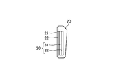
- FIG. 1 is an external view of a room mirror 1 with a display function according to the first embodiment of the present invention as viewed from the driver side who is a user.
- the display-equipped room mirror 1 is in the traveling direction of the vehicle as viewed from the user, as in a normal room mirror, and is generally mounted on the upper part of the windshield.
- the room mirror 1 with a display function includes a mirror surface 21 that reflects the back to the user, a cover 20 that covers the mirror surface 21 and functions as a housing, and a motion sensor 40 that is a sensor that receives a user operation.
- the motion sensor 40 is arranged at the upper center of the room mirror 1 with a display function.
- the arrangement location is not limited. You may arrange
- FIG. 2 is a diagram schematically showing a cross-sectional view taken along a-a ′ of the room mirror 1 with a display function shown in FIG. 1.
- the mirror surface 21 is a surface formed by the half mirror 22.
- a liquid crystal panel 31 and a backlight 32 having substantially the same shape as the half mirror 22 are disposed inside the cover 20.
- the liquid crystal panel 31 and the backlight 32 constitute a display panel 30.
- the display panel 30 is a self-luminous display panel such as an organic EL (Electro Luminescence) panel instead of the combination of the liquid crystal panel 31 and the backlight 32 as long as the displayed image is formed by light emission. Also good.
- a power supply circuit for driving the display panel 30 is not shown.
- the backlight 32 is not turned on when the display panel 30 is not displaying.
- the half mirror 22 reflects most of the light incident on the mirror surface 21.
- the room mirror 1 with a display function operates as a mirror mode in which the user confirms the rear by reflection of the mirror surface 21.
- the backlight 32 is turned on when the display panel 30 is displaying.
- the light emitted by the backlight 32 passes through the half mirror 22 via the liquid crystal panel 31.
- the room mirror 1 with a display function operates as a display mode for displaying an image displayed on the display panel 30.
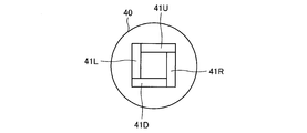
- FIG. 3 is a diagram conceptually showing the motion sensor 40 used by the room mirror 1 with a display function.
- the motion sensor 40 is a sensor in which a plurality of photodiodes are combined. When four photodiodes are combined, motion in four directions can be detected.
- the motion sensor 40 includes an upper direction detection photodiode 41U, a lower direction detection photodiode 41D, a left direction detection photodiode 41L, and a right direction detection photodiode 41R.
- the top, bottom, left, and right of each of these photodiodes are arranged to coincide with the top, bottom, left, and right of the room mirror 1 with a display function as viewed from the user shown in FIG.
- the range in which the motion sensor 40 can detect an object is 0.1 m to 0.2 m in front of the motion sensor 40.
- description will be made by taking four directions of up, down, left, and right as an example.
- the four directions of up, down, left, and right are examples, and are not limited to these four directions.
- the number is not limited to four.
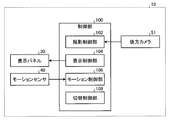
- FIG. 4 is a functional block diagram of the mirror device 10 with a display function according to the first embodiment.
- the mirror device 10 with a display function includes a display panel 30, a motion sensor 40, and a control unit 100 that processes various types of data.
- the control unit 100 includes a CPU (Central Processing Unit), a DSP (Digital Signal Processor), a memory, and the like that perform various data processing.
- the control unit 100 may be built in the room mirror 1 with a display function, or may use a control function such as a navigation device or an in-vehicle computer.
- the control unit 100 includes an imaging control unit 102, a display control unit 104, a motion control unit 106, and a switching control unit 108 based on the function.
- Each function may be realized by a control function mounted on a single device, or may be realized by a control function mounted on a plurality of distributed devices.
- the imaging control unit 102 acquires video data captured by the rear camera 51 mounted in such a direction that the rear of the vehicle on which the mirror device 10 with a display function is mounted can be captured.
- the display control unit 104 performs processing for displaying the video data acquired by the imaging control unit 102 on the display panel 30. Specifically, the display control unit 104 cuts out video data in accordance with the shape of the display panel 30 and adjusts the luminance and color tone of the video.
- the motion control unit 106 acquires an output signal from the motion sensor 40 and detects the direction of the motion and the like.
- the motion control unit 106 analyzes the distribution of the peak value of the detected waveform when each of the four photodiodes included in the motion sensor 40 detects an object, and the object is positioned in front of the motion sensor 40 in any of up, down, left, and right directions. Detect whether it has passed in the direction.
- the motion control unit 106 can detect the reciprocation of the object in the vertical direction when the upward and downward object passages are detected continuously within a predetermined time. Similarly, when the left and right object passages are detected continuously within a predetermined time, the motion control unit 106 can detect the object as a left-right reciprocation.
- the motion control unit 106 always acquires the output value from each photodiode of the motion sensor 40 during a period in which motion should be detected.
- the motion control unit 106 uses the output value Uout of the upward detection photodiode 41U, the output value Dout of the downward detection photodiode 41D, the output value Lout of the left detection photodiode 41L, and the output value Rout of the right detection photodiode 41R. get.
- the motion control unit 106 determines the gesture direction from the peak waveforms of (Uout ⁇ Dout) / (Uout + Dout) and (Rout ⁇ Lout) / (Rout + Lout). Further, when a motion direction opposite to the determined motion direction is detected within a predetermined time set to, for example, 1 second to 2 seconds, it is determined that the motion is a reciprocating motion.
- the switching control unit 108 controls the display control unit 104 based on the detection result of the motion control unit 106. Specifically, when the room mirror 1 with a display function is operating in the mirror mode, control is performed to switch to the display mode in the motion detection result in any of the four directions detected by the motion control unit 106. . Switching from the mirror mode to the display mode is switching from the state in which the video of the rear camera 51 is not displayed to the state in which it is displayed by the control of the display panel 30 by the display control unit 104. When the room mirror 1 with a display function is operating in the display mode, the motion detection in the four directions detected by the motion control unit 106 is processed as an instruction to move the display range with respect to the detected direction.
- the switching control unit 108 performs a process of switching to the mirror mode by detecting the four-way reciprocating motion detected by the motion control unit 106.
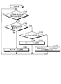
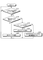
- the switching control unit 108 determines whether or not the motion control unit 106 has detected a motion in any direction (step S101). If no motion is detected in step S101 (step S101: No), the process returns to step S101. In step S101, when motion in any direction is detected (step S101: Yes), the switching control unit 108 operates in the mirror mode, whether the room mirror 1 with a display function is operating in the display mode. (Step S102). The determination in step S102 is made based on whether or not the display control unit 104 displays the video of the rear camera 51 on the display panel 30.
- step S102 when it is determined that the camera is operating in the mirror mode instead of the display mode (step S102: No), the switching control unit 108 controls the display control unit 104 to display the rear camera 51 on the display panel 30. The video is displayed and changed to the display mode (step S103).
- the switching control unit 108 determines whether or not the motion detected by the motion control unit 106 is a reciprocating motion (Ste S104).
- the reciprocating motion is a case where motion in the opposite direction is continuously detected within a preset time such as 1 second to 2 seconds. For example, there is a case where an upward motion is detected and a downward motion is detected within one second. The same applies to the left-right direction.
- step S104 If it is determined in step S104 that the motion is a reciprocating motion (step S104: Yes), the switching control unit 108 changes the operation of the room mirror 1 with a display function to the mirror mode (step S105). If it is determined in step S104 that the motion is not a reciprocating motion (step S104: No), the switching control unit 108 controls the display control unit 104 to shift the display range in the direction of the detected motion (step S104). S106).
- FIGS. 6A to 6E are diagrams conceptually showing examples of shifting the display range in the process of step S106.
- the rear camera 51 is a camera that captures a wide range of the rear of the vehicle.
- the display range 501 is a range in which the display control unit 104 cuts out the shooting range 500 of the rear camera 51 taken by the rear camera 51 as display data of the display panel 30.
- FIG. 6A shows a display range 501 of the rear camera 51 in a normal state with respect to the shooting range 500 of the rear camera 51.
- FIG. 6B is an example when the process of step S106 is executed for the upward motion detection detected in step S101, and the upper part of FIG. 6A is displayed in the display range 501.
- FIG. 6C is an example when the process of step S106 is executed for the downward motion detection detected in step S101, and the lower part of the display range 501 is displayed from FIG. 6A.
- FIG. 6D is an example when the process of step S106 is performed for the left-direction motion detection detected in step S101, and the left side of the display range 501 is displayed from FIG. 6A.
- FIG. 6E shows an example when the process of step S106 is executed for the motion detection in the right direction detected in step S101, and the right side of the display range 501 is displayed from FIG. 6A.
- step S106 may shift a preset maximum shift amount by one motion detection, or a 1 / n shift amount of a preset maximum shift amount by one motion detection.
- the maximum shift amount may be detected by detecting motions in the same direction at most n times.
- the configuration of the mirror device 12 with a display function according to the second embodiment acquires video data taken by the left side camera 52 and the right side camera 53 as shown in FIG. 7 in addition to the rear camera 51. That is, the shooting control unit 103 acquires videos shot by the left camera 52 and the right camera 53 in addition to videos shot by the rear camera 51.
- the display control unit 105 performs processing for displaying the video data of the left side camera 52 and the right side camera 53 on the display panel 35 in addition to the video data of the rear camera 51 acquired by the imaging control unit 103. Specifically, each of the video data in accordance with the shape of the display panel 35 is cut, the brightness and color tone of the video are adjusted, and the respective video data are synthesized.
- FIG. 8 is a conceptual diagram illustrating an example of a camera mounting position and a shooting range from which the mirror device 12 with a display function according to the second embodiment acquires video data, and shows a mode in which the vehicle 200 is viewed from above.
- the arrow indicates the front of the vehicle 200
- the broken lines indicate the photographing ranges of the rear camera 51, the left side camera 52, and the right side camera 53.
- the rear camera 51 is the same as in the first embodiment, but is installed behind the vehicle 200 and captures the rear of the vehicle 200 over a wide range.
- the left-side camera 52 and the right-side camera 53 are installed on the left and right sides of the vehicle 200, respectively, and photograph the left and right rear of the vehicle 200.
- the installation positions of the left side camera 52 and the right side camera 53 are the positions of the door mirrors in the example of FIG. 8, but may be installed at other positions such as the left and right sides of the fender.
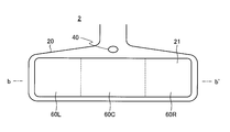
- FIG. 9 is an external view of the room mirror 2 with a display function used in the mirror device 12 with a display function according to the second embodiment as viewed from the driver side who is the user.
- the rear-view mirror with display function 2 is different from the rear-view mirror with display function 1 in that in addition to the video of the rear camera 51 in the display mode, the video of the left-side camera 52 and the right-side camera 53 is displayed.
- the broken lines shown on the mirror surface 21 of the room mirror 2 with a display function shown in FIG. 9 indicate the sections for displaying the images of the respective cameras, the left display section 60L for displaying the images of the left-side camera 52, and the rear camera.
- a central display section 60C for displaying 51 images and a right display section 60R for displaying images of the right-side camera 53 are shown.
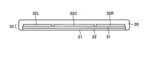
- FIG. 10 is a diagram schematically showing a cross-sectional view taken along the line b-b ′ of the room mirror 2 with a display function shown in FIG. 9.
- a left backlight 32L and a center backlight 32C that can be controlled to be lit independently in correspondence with the positions of the left display section 60L, the central display section 60C, and the right display section 60R.
- a right backlight 32R a left backlight 32L and a center backlight 32C that can be controlled to be lit independently in correspondence with the positions of the left display section 60L, the central display section 60C, and the right display section 60R.
- a right backlight 32R may be independent from each other, or one backlight may be in a lighting controllable state for each section.
- the display panel 35 includes a liquid crystal panel 31, a left backlight 32L, a central backlight 32C, and a right backlight 32R.
- a self-luminous display panel such as an organic EL (Electro Luminescence) panel in which display ON / OFF is controlled for each section It may be.
- the display mode is a state in which images of the rear camera 51, the left camera 52, and the right camera 53 are displayed in the left display section 60L, the central display section 60C, and the right display section 60R. is there.
- display is performed in the left display section 60L and the right display section 60R, and no display is performed in the center display section 60C.
- the display control unit 105 does not display the portion corresponding to the central display section 60C of the liquid crystal panel 31 and turns off the central backlight 32C.
- step S102 when it is determined that the operation is in the mirror mode instead of the display mode (step S102: No), the switching control unit 108 controls the display control unit 105 to control all the sections of the display panel 35. The video is displayed and changed to the display mode (step S203).
- step S104 If it is determined in step S104 that the motion is a reciprocating motion (step S104: Yes), the switching control unit 108 changes the operation of the room mirror 2 with a display function to the mirror mode (step S205).
- the mirror mode changed in step S205 may be the first mirror mode or the second mirror mode.
- step S104 If it is determined in step S104 that the motion is not a reciprocating motion (step S104: No), the switching control unit 108 controls the display control unit 105 to shift the display range in the direction of the detected motion (step S104). S206).
- the display control unit 105 can take the following two types of shift processing.
- As the first shift process only the video of the rear camera 51 displayed in the central display section 60C is shifted, and the left camera 52 and the right camera 53 displayed in the left display section 60L and the right display section 60R. This video is a process that does not shift.
- the images displayed in the left display section 60L and the right display section 60R do not need to be shifted because they correspond to the rear images viewed by the door mirror, and are displayed in the center display section 60C. Since the video corresponds to the video seen by the room mirror, it is shifted as necessary.
- the user can intuitively perform the switching between the mirror mode and the display mode and the operation of the display range of the display target necessary in the display mode without impairing the safety.
- the second shift process in addition to the video of the rear camera 51 displayed in the center display section 60C, the left camera 52 and the right camera displayed in the left display section 60L and the right display section 60R. Similarly, the 53 images are shifted.
- the same display shift can be performed even when the room mirror 2 with a display function cannot change the orientation mechanically. By such processing, the user can intuitively perform the switching between the mirror mode and the display mode and the operation of the display range of the display target in the display mode without impairing the safety.
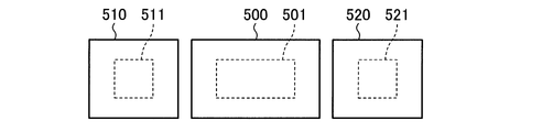
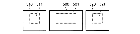
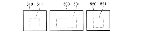
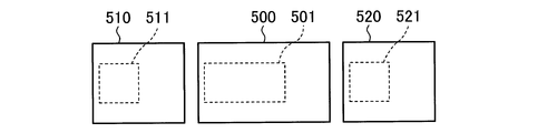
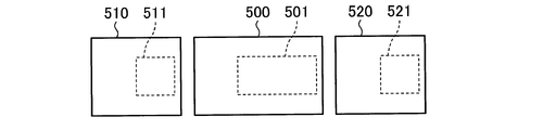
- FIGS. 12A to 12E are diagrams conceptually showing examples of shifting the display range in the process of step S206.
- 12A to 12E show an example of the second shift process.
- the display range 501 in the shooting range 500 of the rear camera 51 is the display data of the rear panel 51 taken by the rear camera 51 by the display control unit 105 as the display data of the display panel 35. It is a range.
- the display range 511 in the shooting range 510 of the left-side camera 52 is the display range of the left-side camera 52 shot by the left-side camera 52 by the display control unit 105.
- the display range 521 in the shooting range 520 of the right-side camera 53 is cut by the display control unit 105 from the shooting range 520 of the right-side camera 53 shot by the right-side camera 53. This is the range of display data.
- the display control unit 105 When the display control unit 105 performs the shift process in each direction, the display range 501 in the shooting range 500 of the rear camera 51, the display range 511 in the shooting range 510 of the left camera 52, and the shooting range 520 of the right camera 53 are displayed.
- the display range 521 is combined and displayed on the liquid crystal panel 31.
- the display range 501 in the shooting range 500 of the rear camera 51 displayed in the shift process of step S106 may be changed as compared with the display range before the shift.
- the display range 501 in the shooting range 500 of the rear camera 51 after the shift is narrower than that before the shift, the same effect as the zoom of the display range can be obtained. For this reason, it is possible to visually check the range in which the instruction to move the display range is given by motion detection.
- the display range 501 in the shooting range 500 of the rear camera 51 after the shift is made wider than that before the shift, the display range can be widened.
- These processes may be set in advance, or may be determined by the time length of the peak waveform indicating the motion detected in step S101. Specifically, if the peak waveform indicating the motion detected in step S101 is less than 0.4 seconds as an example of the threshold value, the display range 501 in the shooting range 500 of the rear camera 51 after the shift is narrower than before the shift, If the time length is equal to or greater than the threshold and the upper limit is recognized as a motion, the display range 501 in the shooting range 500 of the rear camera 51 after the shift is made wider than before the shift.
- the display in the imaging range 510 of the left camera 52 corresponding to the motion detection direction Either the range 511 or the display range 521 in the shooting range 520 of the right side camera 53 is cut out narrowly, and if it is equal to or larger than the threshold, it is cut out widely.
- the mirror device with a display function and the display switching method according to the present invention are useful when displaying an image of a camera that captures the rear of the vehicle, etc., on a rearview mirror attached to the interior of the vehicle. Suitable for switching functions and operating the display range.
Landscapes
- Engineering & Computer Science (AREA)
- Multimedia (AREA)
- Mechanical Engineering (AREA)
- Signal Processing (AREA)
- Physics & Mathematics (AREA)
- Computer Hardware Design (AREA)
- General Physics & Mathematics (AREA)
- Theoretical Computer Science (AREA)
- Closed-Circuit Television Systems (AREA)
- Controls And Circuits For Display Device (AREA)
- Fittings On The Vehicle Exterior For Carrying Loads, And Devices For Holding Or Mounting Articles (AREA)
Priority Applications (3)
| Application Number | Priority Date | Filing Date | Title |
|---|---|---|---|
| EP15840456.6A EP3192700B1 (en) | 2014-09-10 | 2015-09-03 | Display function-equipped mirror device and display switching method |
| CN201580048449.8A CN106687334B (zh) | 2014-09-10 | 2015-09-03 | 带显示功能的后视镜装置以及显示切换方法 |
| US15/453,950 US20170174137A1 (en) | 2014-09-10 | 2017-03-09 | Mirror device with display function and display switching method |
Applications Claiming Priority (2)
| Application Number | Priority Date | Filing Date | Title |
|---|---|---|---|
| JP2014184110A JP5983693B2 (ja) | 2014-09-10 | 2014-09-10 | 表示機能付きミラー装置および表示切替方法 |
| JP2014-184110 | 2014-09-10 |
Related Child Applications (1)
| Application Number | Title | Priority Date | Filing Date |
|---|---|---|---|
| US15/453,950 Continuation US20170174137A1 (en) | 2014-09-10 | 2017-03-09 | Mirror device with display function and display switching method |
Publications (1)
| Publication Number | Publication Date |
|---|---|
| WO2016039256A1 true WO2016039256A1 (ja) | 2016-03-17 |
Family
ID=55459004
Family Applications (1)
| Application Number | Title | Priority Date | Filing Date |
|---|---|---|---|
| PCT/JP2015/075121 Ceased WO2016039256A1 (ja) | 2014-09-10 | 2015-09-03 | 表示機能付きミラー装置および表示切替方法 |
Country Status (5)
| Country | Link |
|---|---|
| US (1) | US20170174137A1 (enExample) |
| EP (1) | EP3192700B1 (enExample) |
| JP (1) | JP5983693B2 (enExample) |
| CN (1) | CN106687334B (enExample) |
| WO (1) | WO2016039256A1 (enExample) |
Cited By (1)
| Publication number | Priority date | Publication date | Assignee | Title |
|---|---|---|---|---|
| CN107813763A (zh) * | 2016-09-14 | 2018-03-20 | 株式会社东海理化电机制作所 | 车辆用目视确认装置 |
Families Citing this family (13)
| Publication number | Priority date | Publication date | Assignee | Title |
|---|---|---|---|---|
| US12476966B2 (en) | 2015-06-26 | 2025-11-18 | Cecelumen, Llc | Methods and apparatus for providing biometric authentication and authorization services |
| KR102552388B1 (ko) * | 2016-09-27 | 2023-07-06 | 주식회사 에스엘미러텍 | 차량용 인사이드 미러 기반의 제어 장치, 그리고 이에 적용되는 방법 |
| JP6816475B2 (ja) * | 2016-11-30 | 2021-01-20 | 株式会社Jvcケンウッド | 車両用表示装置および表示方法 |
| JP6816476B2 (ja) * | 2016-11-30 | 2021-01-20 | 株式会社Jvcケンウッド | 車両用表示装置および表示方法 |
| US20190098226A1 (en) * | 2017-09-26 | 2019-03-28 | Panasonic Automotive Systems Company Of America, Division Of Panasonic Corporation Of North America | Smart field of view (fov) adjustment for a rearview display system in a motor vehicle |
| US10921484B2 (en) * | 2017-11-21 | 2021-02-16 | Reliance Core Consulting | Methods and systems for detecting motion corresponding to a field of interest |
| EP3659862B1 (en) * | 2018-11-27 | 2021-09-29 | SMR Patents S.à.r.l. | Pivotable interior mirror for a motor vehicle |
| JP6769500B2 (ja) * | 2019-02-13 | 2020-10-14 | 株式会社Jvcケンウッド | 車両用映像制御装置、車両用映像システム、映像制御方法、及びプログラム |
| US11558584B2 (en) * | 2019-07-11 | 2023-01-17 | Chris Pritchard | Systems and methods for providing real-time surveillance in automobiles |
| US11675431B2 (en) * | 2019-09-30 | 2023-06-13 | Mitsubishi Electric Corporation | Image display device, display control device, and display control method, and program and recording medium |
| US12235980B2 (en) | 2020-10-21 | 2025-02-25 | Cecelumen, Llc | Methods and apparatus for automatically censoring, modifying and/or controlling distribution of images including multiple people |
| US20220230457A1 (en) * | 2021-01-18 | 2022-07-21 | James Buscemi | Methods and apparatus for maintaining privacy of license plate and/or other information |
| KR20230173770A (ko) * | 2022-06-17 | 2023-12-27 | 현대자동차주식회사 | 차량 및 차량의 제어방법 |
Citations (5)
| Publication number | Priority date | Publication date | Assignee | Title |
|---|---|---|---|---|
| JP2002120649A (ja) * | 2000-08-07 | 2002-04-23 | Ichikoh Ind Ltd | モニタ内蔵ルームミラー |
| JP2005189725A (ja) * | 2003-12-26 | 2005-07-14 | Denso Corp | 車両用情報表示システム |
| JP2010130647A (ja) * | 2008-12-01 | 2010-06-10 | Aisin Seiki Co Ltd | 車両周辺確認装置 |
| JP2012046099A (ja) * | 2010-08-27 | 2012-03-08 | Tokai Rika Co Ltd | 無線インターフェース装置及び電子キー |
| JP2014015198A (ja) * | 2011-12-09 | 2014-01-30 | Nissan Motor Co Ltd | 映像表示ミラー |
Family Cites Families (2)
| Publication number | Priority date | Publication date | Assignee | Title |
|---|---|---|---|---|
| EP2487069B1 (de) * | 2011-02-14 | 2014-04-09 | SMR Patents S.à.r.l. | Innenrückblickeinheit für Kraftfahrzeuge |
| CN203580780U (zh) * | 2013-10-08 | 2014-05-07 | 沈易宽 | 内后视镜 |
-
2014
- 2014-09-10 JP JP2014184110A patent/JP5983693B2/ja active Active
-
2015
- 2015-09-03 CN CN201580048449.8A patent/CN106687334B/zh active Active
- 2015-09-03 WO PCT/JP2015/075121 patent/WO2016039256A1/ja not_active Ceased
- 2015-09-03 EP EP15840456.6A patent/EP3192700B1/en active Active
-
2017
- 2017-03-09 US US15/453,950 patent/US20170174137A1/en not_active Abandoned
Patent Citations (5)
| Publication number | Priority date | Publication date | Assignee | Title |
|---|---|---|---|---|
| JP2002120649A (ja) * | 2000-08-07 | 2002-04-23 | Ichikoh Ind Ltd | モニタ内蔵ルームミラー |
| JP2005189725A (ja) * | 2003-12-26 | 2005-07-14 | Denso Corp | 車両用情報表示システム |
| JP2010130647A (ja) * | 2008-12-01 | 2010-06-10 | Aisin Seiki Co Ltd | 車両周辺確認装置 |
| JP2012046099A (ja) * | 2010-08-27 | 2012-03-08 | Tokai Rika Co Ltd | 無線インターフェース装置及び電子キー |
| JP2014015198A (ja) * | 2011-12-09 | 2014-01-30 | Nissan Motor Co Ltd | 映像表示ミラー |
Cited By (1)
| Publication number | Priority date | Publication date | Assignee | Title |
|---|---|---|---|---|
| CN107813763A (zh) * | 2016-09-14 | 2018-03-20 | 株式会社东海理化电机制作所 | 车辆用目视确认装置 |
Also Published As
| Publication number | Publication date |
|---|---|
| CN106687334B (zh) | 2018-06-15 |
| CN106687334A (zh) | 2017-05-17 |
| JP2016055782A (ja) | 2016-04-21 |
| EP3192700B1 (en) | 2018-10-24 |
| EP3192700A1 (en) | 2017-07-19 |
| JP5983693B2 (ja) | 2016-09-06 |
| EP3192700A4 (en) | 2017-08-30 |
| US20170174137A1 (en) | 2017-06-22 |
Similar Documents
| Publication | Publication Date | Title |
|---|---|---|
| JP5983693B2 (ja) | 表示機能付きミラー装置および表示切替方法 | |
| JP2016055782A5 (enExample) | ||
| US11052823B2 (en) | Vehicle rear monitoring system | |
| JP5277974B2 (ja) | 運転支援装置 | |
| CN109937158B (zh) | 具有眼睛跟踪的后视系统 | |
| US20200279094A1 (en) | Vehicle safety system with no-control operation | |
| JP6315102B2 (ja) | 表示機能付きミラー装置および表示機能付きミラー装置の機能変更方法 | |
| JP6481971B2 (ja) | 乗員撮影装置 | |
| JP6585662B2 (ja) | 車両ルーフ搭載システム | |
| JP2017202741A (ja) | 車両用視認装置 | |
| JP6481970B2 (ja) | ドライバ撮影装置 | |
| US20160368418A1 (en) | Rear-view monitor device and automobile equipeed with same | |
| JP6229769B2 (ja) | 表示機能付きミラー装置および表示切替方法 | |
| JP2009035162A (ja) | 後方視認装置 | |
| EP2709356A2 (en) | Method for operating a front camera of a motor vehicle considering the light of the headlight, corresponding device and motor vehicle | |
| US10261580B2 (en) | Mirror device with display function and method of changing direction of mirror device with display function | |
| JP2019001293A (ja) | 車載用表示装置 | |
| JP2018002152A (ja) | 表示機能付きミラー装置および表示切替方法 | |
| JP7131354B2 (ja) | 表示制御装置、表示制御システム、表示制御方法、および表示制御プログラム | |
| JP2010208372A (ja) | 輝度調整装置 | |
| CN118457424A (zh) | 驾驶辅助装置 | |
| WO2017169087A1 (ja) | 電子ミラーの電気回路 | |
| JP6593713B2 (ja) | 乗員撮影装置 | |
| JP2018074440A (ja) | 車両後方画像表示装置 | |
| JP6649791B2 (ja) | 車両用オーナメント |
Legal Events
| Date | Code | Title | Description |
|---|---|---|---|
| 121 | Ep: the epo has been informed by wipo that ep was designated in this application |
Ref document number: 15840456 Country of ref document: EP Kind code of ref document: A1 |
|
| REEP | Request for entry into the european phase |
Ref document number: 2015840456 Country of ref document: EP |
|
| WWE | Wipo information: entry into national phase |
Ref document number: 2015840456 Country of ref document: EP |
|
| NENP | Non-entry into the national phase |
Ref country code: DE |