EP3192700B1 - Display function-equipped mirror device and display switching method - Google Patents
Display function-equipped mirror device and display switching method Download PDFInfo
- Publication number
- EP3192700B1 EP3192700B1 EP15840456.6A EP15840456A EP3192700B1 EP 3192700 B1 EP3192700 B1 EP 3192700B1 EP 15840456 A EP15840456 A EP 15840456A EP 3192700 B1 EP3192700 B1 EP 3192700B1
- Authority
- EP
- European Patent Office
- Prior art keywords
- display
- mirror
- rearview mirror
- display function
- mode
- Prior art date
- Legal status (The legal status is an assumption and is not a legal conclusion. Google has not performed a legal analysis and makes no representation as to the accuracy of the status listed.)
- Active
Links
- 238000000034 method Methods 0.000 title claims description 14
- 230000033001 locomotion Effects 0.000 claims description 105
- 238000001514 detection method Methods 0.000 claims description 42
- 238000003384 imaging method Methods 0.000 claims description 9
- 238000010586 diagram Methods 0.000 description 22
- 239000004973 liquid crystal related substance Substances 0.000 description 11
- 238000005401 electroluminescence Methods 0.000 description 4
- 230000002269 spontaneous effect Effects 0.000 description 2
- 230000015572 biosynthetic process Effects 0.000 description 1
- 230000006735 deficit Effects 0.000 description 1
- 230000000694 effects Effects 0.000 description 1
- 238000009434 installation Methods 0.000 description 1
- 230000002265 prevention Effects 0.000 description 1
- 238000003786 synthesis reaction Methods 0.000 description 1
Images


Classifications
-
- B—PERFORMING OPERATIONS; TRANSPORTING
- B60—VEHICLES IN GENERAL
- B60R—VEHICLES, VEHICLE FITTINGS, OR VEHICLE PARTS, NOT OTHERWISE PROVIDED FOR
- B60R1/00—Optical viewing arrangements; Real-time viewing arrangements for drivers or passengers using optical image capturing systems, e.g. cameras or video systems specially adapted for use in or on vehicles
- B60R1/12—Mirror assemblies combined with other articles, e.g. clocks
-
- B—PERFORMING OPERATIONS; TRANSPORTING
- B60—VEHICLES IN GENERAL
- B60R—VEHICLES, VEHICLE FITTINGS, OR VEHICLE PARTS, NOT OTHERWISE PROVIDED FOR
- B60R1/00—Optical viewing arrangements; Real-time viewing arrangements for drivers or passengers using optical image capturing systems, e.g. cameras or video systems specially adapted for use in or on vehicles
- B60R1/02—Rear-view mirror arrangements
- B60R1/04—Rear-view mirror arrangements mounted inside vehicle
-
- G—PHYSICS
- G09—EDUCATION; CRYPTOGRAPHY; DISPLAY; ADVERTISING; SEALS
- G09G—ARRANGEMENTS OR CIRCUITS FOR CONTROL OF INDICATING DEVICES USING STATIC MEANS TO PRESENT VARIABLE INFORMATION
- G09G5/00—Control arrangements or circuits for visual indicators common to cathode-ray tube indicators and other visual indicators
- G09G5/14—Display of multiple viewports
-
- H—ELECTRICITY
- H04—ELECTRIC COMMUNICATION TECHNIQUE
- H04N—PICTORIAL COMMUNICATION, e.g. TELEVISION
- H04N7/00—Television systems
- H04N7/18—Closed-circuit television [CCTV] systems, i.e. systems in which the video signal is not broadcast
-
- H—ELECTRICITY
- H04—ELECTRIC COMMUNICATION TECHNIQUE
- H04N—PICTORIAL COMMUNICATION, e.g. TELEVISION
- H04N7/00—Television systems
- H04N7/18—Closed-circuit television [CCTV] systems, i.e. systems in which the video signal is not broadcast
- H04N7/181—Closed-circuit television [CCTV] systems, i.e. systems in which the video signal is not broadcast for receiving images from a plurality of remote sources
-
- B—PERFORMING OPERATIONS; TRANSPORTING
- B60—VEHICLES IN GENERAL
- B60R—VEHICLES, VEHICLE FITTINGS, OR VEHICLE PARTS, NOT OTHERWISE PROVIDED FOR
- B60R1/00—Optical viewing arrangements; Real-time viewing arrangements for drivers or passengers using optical image capturing systems, e.g. cameras or video systems specially adapted for use in or on vehicles
- B60R1/12—Mirror assemblies combined with other articles, e.g. clocks
- B60R2001/1253—Mirror assemblies combined with other articles, e.g. clocks with cameras, video cameras or video screens
-
- B—PERFORMING OPERATIONS; TRANSPORTING
- B60—VEHICLES IN GENERAL
- B60R—VEHICLES, VEHICLE FITTINGS, OR VEHICLE PARTS, NOT OTHERWISE PROVIDED FOR
- B60R2300/00—Details of viewing arrangements using cameras and displays, specially adapted for use in a vehicle
- B60R2300/20—Details of viewing arrangements using cameras and displays, specially adapted for use in a vehicle characterised by the type of display used
- B60R2300/207—Details of viewing arrangements using cameras and displays, specially adapted for use in a vehicle characterised by the type of display used using multi-purpose displays, e.g. camera image and navigation or video on same display
-
- B—PERFORMING OPERATIONS; TRANSPORTING
- B60—VEHICLES IN GENERAL
- B60R—VEHICLES, VEHICLE FITTINGS, OR VEHICLE PARTS, NOT OTHERWISE PROVIDED FOR
- B60R2300/00—Details of viewing arrangements using cameras and displays, specially adapted for use in a vehicle
- B60R2300/30—Details of viewing arrangements using cameras and displays, specially adapted for use in a vehicle characterised by the type of image processing
- B60R2300/301—Details of viewing arrangements using cameras and displays, specially adapted for use in a vehicle characterised by the type of image processing combining image information with other obstacle sensor information, e.g. using RADAR/LIDAR/SONAR sensors for estimating risk of collision
-
- B—PERFORMING OPERATIONS; TRANSPORTING
- B60—VEHICLES IN GENERAL
- B60R—VEHICLES, VEHICLE FITTINGS, OR VEHICLE PARTS, NOT OTHERWISE PROVIDED FOR
- B60R2300/00—Details of viewing arrangements using cameras and displays, specially adapted for use in a vehicle
- B60R2300/80—Details of viewing arrangements using cameras and displays, specially adapted for use in a vehicle characterised by the intended use of the viewing arrangement
- B60R2300/802—Details of viewing arrangements using cameras and displays, specially adapted for use in a vehicle characterised by the intended use of the viewing arrangement for monitoring and displaying vehicle exterior blind spot views
- B60R2300/8026—Details of viewing arrangements using cameras and displays, specially adapted for use in a vehicle characterised by the intended use of the viewing arrangement for monitoring and displaying vehicle exterior blind spot views in addition to a rear-view mirror system
-
- B—PERFORMING OPERATIONS; TRANSPORTING
- B60—VEHICLES IN GENERAL
- B60R—VEHICLES, VEHICLE FITTINGS, OR VEHICLE PARTS, NOT OTHERWISE PROVIDED FOR
- B60R2300/00—Details of viewing arrangements using cameras and displays, specially adapted for use in a vehicle
- B60R2300/80—Details of viewing arrangements using cameras and displays, specially adapted for use in a vehicle characterised by the intended use of the viewing arrangement
- B60R2300/8066—Details of viewing arrangements using cameras and displays, specially adapted for use in a vehicle characterised by the intended use of the viewing arrangement for monitoring rearward traffic
-
- G—PHYSICS
- G09—EDUCATION; CRYPTOGRAPHY; DISPLAY; ADVERTISING; SEALS
- G09G—ARRANGEMENTS OR CIRCUITS FOR CONTROL OF INDICATING DEVICES USING STATIC MEANS TO PRESENT VARIABLE INFORMATION
- G09G2320/00—Control of display operating conditions
- G09G2320/08—Arrangements within a display terminal for setting, manually or automatically, display parameters of the display terminal
-
- G—PHYSICS
- G09—EDUCATION; CRYPTOGRAPHY; DISPLAY; ADVERTISING; SEALS
- G09G—ARRANGEMENTS OR CIRCUITS FOR CONTROL OF INDICATING DEVICES USING STATIC MEANS TO PRESENT VARIABLE INFORMATION
- G09G2320/00—Control of display operating conditions
- G09G2320/10—Special adaptations of display systems for operation with variable images
-
- G—PHYSICS
- G09—EDUCATION; CRYPTOGRAPHY; DISPLAY; ADVERTISING; SEALS
- G09G—ARRANGEMENTS OR CIRCUITS FOR CONTROL OF INDICATING DEVICES USING STATIC MEANS TO PRESENT VARIABLE INFORMATION
- G09G2380/00—Specific applications
- G09G2380/10—Automotive applications
Definitions
- the present invention relates to a mirror device with a display function, the mirror device having an image display function as well as a reflection function, and a display switching method.
- a rearview mirror attached inside an interior of an automobile and provided with a display function has been proposed.
- the display function a picture of a camera that captures the rear of the automobile is displayed.
- JP 2001-191858 A discloses a rearview mirror including a monitor device on a back surface of a half mirror, and displaying a plurality of camera pictures at the same time. Further, JP 2009-100180 A discloses a rearview mirror that changes a display size of a captured image.
- EP 2 487 069 A discloses an internal retrospection unit including a foot and a projection surface, which is arranged on a head portion.
- a detection unit is provided for detecting the gestures by capturing different positions and orientations of a body portion of a vehicle occupant in a vehicle interior section for performing an individual adjustment of the internal retrospection unit by the gesture.
- a range to display an image in the rearview mirror with a display function can be changed by setting a cutting range of the image captured with a camera.
- Switching of the functions and an operation of the display range of the rearview mirror with a display function are often performed during driving of the automobile, and prevention of impairment of safety is required. Therefore, these operations are desirably not independent operation systems, and are desirably a unified operation system. Further, it is desirable that these operations are intuitively operable for the user during driving, and a mistake of an operation does not occur.
- a mirror device with a display function includes, a rearview mirror with a display function, the rearview mirror including a display panel that displays a picture of an imaging device that captures rear of a vehicle, and a half mirror provided in a display surface of the display panel, a motion sensor configured to perform motion detection, and a switching control unit configured to perform processing of switching a function to the display function that executes display on the display panel, in a motion detection result in any direction of directions detected by the motion sensor, when the rearview mirror with a display function functions as a rearview mirror using a mirror surface of the half mirror and the display on the display panel is stopped, and process the motion detection detected by the motion sensor as a moving instruction of a display range to each of the directions, when the rearview mirror with a display function is executing the display function in which the display on the display panel is being executed.
- a display switching method includes switching a function to a display function that executes display on a display panel, in a motion detection result in any direction of directions detected by a motion sensor that performs motion detection, when a rearview mirror with a display function including a display panel that displays a picture of an imaging device that captures rear of a vehicle, and a half mirror provided in a display surface of the display panel functions as a rearview mirror using a mirror surface of the half mirror and the display on the display panel is stopped, and performing a moving instruction of a display range to each of the directions, by the motion detection detected by the motion sensor, when the rearview mirror with a display function is executing the display function in which the display on the display panel is being performed.
- the switching of functions and the operation of a display range can be intuitively performed without impairing safety.
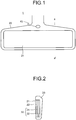
- FIG. 1 is an external view of a rearview mirror with a display function 1 according to a first embodiment of the present invention as viewed from a driver side as a user.
- the rearview mirror with a display function 1 is attached in a traveling direction of a vehicle as viewed from the user and is typically attached to an upper portion of a windshield or the like, similarly to a normal rearview mirror.
- the rearview mirror with a display function 1 includes a mirror surface 21 that reflects the rear to the user, a cover 20 that covers the mirror surface 21 and functions as a housing, and a motion sensor 40 as a sensor that receives an operation of the user.
- the motion sensor 40 is arranged in a central upper portion of the rearview mirror with a display function 1.
- the arrangement location is not limited as long as the motion sensor 40 can properly recognize a motion for the purpose of the operation of the user without a mistake, and the motion sensor 40 may be arranged at a position separated from the rearview mirror with a display function 1.
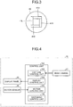
- FIG. 2 is a diagram schematically illustrating a sectional view of a-a' of the rearview mirror with a display function 1 illustrated in FIG. 1 .
- the mirror surface 21 is a surface configured by a half mirror 22.
- a liquid crystal panel 31 and a backlight 32 having nearly the same shape as the half mirror 22 are arranged inside the cover 20.
- the liquid crystal panel 31 and the backlight 32 configure a display panel 30.
- the display panel 30 may be a spontaneous light emitting display panel such as an organic electro luminescence (EL) panel, in place of the combination of the liquid crystal panel 31 and the backlight 32 as long as it has a configuration in which a picture to be displayed is formed by emission of light.
- EL organic electro luminescence
- the backlight 32 is not lighted.
- the half mirror 22 reflects the most part of light incident on the mirror surface 21. Therefore, the rearview mirror with a display function 1 is operated in a mirror mode in which the user confirms the rear with the reflection on the mirror surface 21.
- the backlight 32 is lighted. At this time, light emitted by the backlight 32 is transmitted through the half mirror 22 via the liquid crystal panel 31. Therefore, the rearview mirror with a display function 1 is operated in a display mode in which a picture to be displayed on the display panel 30 is displayed.
- FIG. 3 is a diagram conceptually illustrating the motion sensor 40 used in the rearview mirror with a display function 1.
- the motion sensor 40 is a sensor in which a plurality of photodiodes is combined. In a case where four photodiodes are combined, the motion sensor 40 can detect motions in four directions.
- the motion sensor 40 includes an upward direction detection photodiode 41U, a downward direction detection photodiode 41D, a left direction detection photodiode 41L, and a right direction detection photodiode 41R therein.
- the upward, downward, right, and left directions of the photodiodes are arranged in conformity to upward, downward, right, and left directions of the rearview mirror with a display function 1 as viewed from the user, illustrated in FIG.
- a detectable range of an object by such a motion sensor 40 is 0.1 to 0.2 m in front of the motion sensor 40.
- four directions of the upward, downward, right, and left will be exemplarily described for convenience of description.
- the upward, downward, right, and left directions are an example, and the present embodiment is not limited to the four directions and the number of directions is not limited to four.
- FIG. 4 is a diagram illustrating a functional block diagram of a mirror device with a display function 10 according to the first embodiment.
- the mirror device with a display function 10 is configured of the display panel 30 and the motion sensor 40 that configure the rearview mirror with a display function 1, and a control unit 100 that processes various data.
- the control unit 100 is configured of a central processing unit (CPU) that processes various data, a digital signal processor (DSP), a memory, and the like.
- DSP digital signal processor
- the control unit 100 may be built in the rearview mirror with a display function 1, and control functions of a navigation device, an on-vehicle computer, and the like may be used.
- the control unit 100 includes a capture control unit 102, a display control unit 104, a motion control unit 106, and a switching control unit 108 on the basis of its functions.
- Each of the functions may be realized by control functions mounted on a single device, or may be realized by control functions mounted on a plurality of distributed devices.
- the capture control unit 102 acquires picture data captured by a rear camera 51, which is mounted in a direction to be able to capture the rear of the vehicle on which the mirror device with a display function 10 is mounted.
- the display control unit 104 performs processing of displaying, on the display panel 30, the picture data acquired by the capture control unit 102. To be specific, the display control unit 104 adjusts cutting of the picture data in accordance with the shape of the display panel 30, and the brightness and tone of the picture.
- the motion control unit 106 acquires an output signal from the motion sensor 40, and detects a direction of a motion and the like.
- the motion control unit 106 analyzes distribution of peak values of detected waveforms of when each of the four photodiodes included in the motion sensor 40 detects an object, and detects which direction of the upward, downward, right, and left directions the object has passed in front of the motion sensor 40. Further, the motion control unit 106 can detect the direction as reciprocation of the object in the upward and downward direction when continuously detecting passage of the object in the upward direction and the downward direction within a predetermined time. Similarly, the motion control unit 106 can detect the direction as reciprocation of the object in the right and left direction when continuously detecting passage of the object in the left direction and the right direction within a predetermined time.
- the motion control unit 106 acquires output values from each of the photodiodes of the motion sensor 40 on a steady basis during a term in which the motion should be detected.
- the motion control unit 106 acquires an output value Uout of the upward direction detection photodiode 41U, an output value Dout of the downward direction detection photodiode 41D, an output value Lout of the left direction detection photodiode 41L, and an output value Rout of the right direction detection photodiode 41R.
- the motion control unit 106 determines a gesture direction from peak waveforms of (Uout - Dout)/(Uout + Dout), and (Rout - Lout)/(Rout + Lout), for example. Further, the motion control unit 106 determines that the motion is a reciprocating motion when detecting a motion direction in an opposite direction to the determined motion direction within a predetermined time, which is set to one to two seconds, for example.
- the switching control unit 108 controls the display control unit 104 on the basis of a detection result of the motion control unit 106.
- the switching control unit 108 performs control to switch the mirror mode to the display mode in a motion detection result in any of the four directions detected by the motion control unit 106.
- Switching from the mirror mode to the display mode is a control by the display control unit 104 for the display panel 30, and is to switch from a state in which no picture of the rear camera 51 is displayed to a state in which a picture is displayed.
- the motion detection of the four directions detected by the motion control unit 106 is processed as a moving instruction of the display range to the detected directions.
- the switching control unit 108 performs processing of switching from the display mode to the mirror mode by reciprocating motion detection of the four directions detected by the motion control unit 106 when the rearview mirror with a display function 1 is being operated in the display mode.
- the switching control unit 108 determines whether the motion control unit 106 has detected a motion in any direction (step S101). In step S101, when the motion has not been detected (No in step S101), the processing returns to step S101. In step S101, when the motion in any direction has been detected (Yes in step S101), the switching control unit 108 determines whether the rearview mirror with a display function 1 is being operated in the display mode or in the mirror mode (step S102). The determination of step S102 is made according to whether the display control unit 104 causes the display panel 30 to be displaying the picture of the rear camera 51.
- step S102 when the rearview mirror with a display function 1 is determined to be being operated in the mirror mode, instead of the display mode (No in step S102), the switching control unit 108 controls the display control unit 104 to cause the display panel 30 to display the picture of the rear camera 51, and changes the mirror mode to the display mode (step S103).
- step S102 when the rearview mirror with a display function 1 is determined to be being operated in the display mode (Yes in step S102), the switching control unit 108 determines whether the motion detected by the motion control unit 106 is a reciprocating motion (step S104).
- the reciprocating motion is determined in a case where a motion in an opposite direction is continuously detected within a time set in advance such as one to two seconds. The case is, for example, when a motion in the downward direction is detected within one second after a motion in the upward direction is detected. The same applies to the right and left direction.
- step S104 when the motion is determined to be a reciprocating motion (Yes in step S104), the switching control unit 108 changes the operation of the rearview mirror with a display function 1 to the mirror mode (step S105).
- step S104 when the motion is determined not to be a reciprocating motion (No in step S104), the switching control unit 108 controls the display control unit 104 to shift the display range in the direction of the detected motion (step S106).
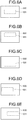
- FIGS. 6A to 6E are diagrams conceptually illustrating shift examples of the display range in the processing of step S106.
- the rear camera 51 is a camera that captures the rear of the vehicle in a wide range.
- a display range 501 is a range in which a capture range 500 of the rear camera 51, which is captured by the rear camera 51, is cut by the display control unit 104, and the cut range is displayed as display data of the display panel 30.
- FIG. 6A illustrates the display range 501 of the rear camera 51 in a normal state with respect to the capture range 500 of the rear camera 51.
- FIG. 6B illustrates an example of when the processing of step S106 is executed for the motion detection in the upward direction detected in step S101, and an upper portion than the portion of FIG. 6A is displayed regarding the display range 501.
- FIG. 6C illustrates an example of when the processing of step S106 is executed for the motion detection in the downward direction detected in step S101, and a lower portion than the portion of FIG. 6A is displayed regarding the display range 501.
- FIG. 6D illustrates an example of when the processing of step S106 is executed for the motion detection in the left direction detected in step S101, and a more left portion than the portion of FIG.
- FIG. 6A is displayed regarding the display range 501.
- FIG. 6E illustrates an example of when the processing of step S106 is executed for the motion detection in the right direction detected in step S101, and a more right portion than the portion of FIG. 6A is displayed regarding the display range 501.
- step S106 may be performed such that the display range is shifted by a maximum shift amount set in advance in the motion detection of one time, or the display range may be shifted by a 1/n shift amount of the maximum shift amount set in advance in the motion detection of one time, and then the display range may be shifted up to the maximum shift amount in the motion detection of up to n times in the same direction.
- a configuration of a mirror device with a display function 12 according to the second embodiment acquires picture data captured by a left-side camera 52 and a right-side camera 53, as illustrated in FIG. 7 , in addition to a rear camera 51. That is, a capture control unit 103 acquires pictures captured by each of the left-side camera 52 and the right-side camera 53, in addition to a picture captured by the rear camera 51.
- a display control unit 105 performs processing of displaying the picture data of the left-side camera 52 and the right-side camera 53 on a display panel 35, in addition to the picture data of the rear camera 51 acquired by the capture control unit 103. To be specific, the display control unit 105 performs cutting of each of the picture data in accordance with the shape of the display panel 35, adjustment of brightness and tone of the pictures, synthesis of the picture data, and the like.
- FIG. 8 is a conceptual diagram illustrating an example of attaching positions and capture ranges of the cameras with which the mirror device with a display function 12 according to the second embodiment acquires the picture data, and illustrates a state as viewed from above a vehicle 200.
- the arrow represents the front of the vehicle 200
- the broken lines represent respective capture ranges of the rear camera 51, the left-side camera 52, and the right-side camera 53.
- the rear camera 51 is arranged on the rear of the vehicle 200, and captures the rear of the vehicle 200 in a wide range, which is similar to the first embodiment.
- the right-side camera 53 and the left-side camera 52 are arranged on right and left sides of the vehicle 200, respectively, and capture the right rear and left rear of vehicle 200.
- Installation positions of the right-side camera 53 and the left-side camera 52 are positions of wing mirrors in the example of FIG. 8 .
- the right-side camera 53 and the left-side camera 52 may be installed at other positions such as right and left sides of fenders.
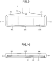
- FIG. 9 is an external view of a rearview mirror with a display function 2 used in the mirror device with a display function 12 according to the second embodiment as viewed from a driver side as a user.
- the rearview mirror with a display function 2 is different from the rearview mirror with a display function 1 in that the pictures of the left-side camera 52 and the right-side camera 53 are displayed, in addition to the picture of the rear camera 51, in a display mode.
- the broken lines illustrated in the mirror surface 21 of the rearview mirror with a display function 2 illustrated in FIG. 9 represent sections in which the pictures of each of the cameras are displayed.
- a left display section 60L in which the picture of the left-side camera 52 is displayed, a central display section 60C in which the picture of the rear camera 51 is displayed, and a right display section 60R in which the picture of the right-side camera 53 is displayed are illustrated.
- FIG. 10 is a diagram schematically illustrating a sectional view of b-b' of the rearview mirror with a display function 2 illustrated in FIG. 9 .
- independently light-controllable left backlight 32L, central backlight 32C, and right backlight 32R are provided in the rear of a liquid crystal panel 31, corresponding to the positions of the left display section 60L, the central display section 60C, and the right display section 60R. These backlights may be independent of each other, or one backlight may be light-controllable in each section.
- the display panel 35 is configured of the liquid crystal panel 31, the left backlight 32L, the central backlight 32C, and the right backlight 32R.
- a spontaneous light emitting display panel such as an organic electro luminescence (EL) panel that controls ON/OFF of display in each section may be employed in place of the combination of the liquid crystal panel 31, the left backlight 32L, the central backlight 32C, and the right backlight 32R.
- EL organic electro luminescence
- a display mode is a state in which the pictures of the rear camera 51, the left-side camera 52, and the right-side camera 53 are displayed in the left display section 60L, the central display section 60C, and the right display section 60R.
- a mirror mode includes two patterns. In a first mirror mode, display is not performed in all of the sections. In the second mirror mode, display is performed in the left display section 60L and the right display section 60R, and display is not performed in the central display section 60C.
- the display control unit 105 does not perform display of a portion corresponding to the central display section 60C of the liquid crystal panel 31 and puts off the central backlight 32C.
- step S102 when the rearview mirror with a display function 2 is determined to be being operated in the mirror mode instead of the display mode (No in step S102), a switching control unit 108 controls the display control unit 105 to display the pictures in all of the sections of the display panel 35, and changes the mirror mode to the display mode (step S203).
- step S104 when a motion is determined to be a reciprocating motion (Yes in step S104), the switching control unit 108 changes the operation of the rearview mirror with a display function 2 to the mirror mode (step S205).
- the mirror mode changed in step S205 may be the first mirror mode or may be the second mirror mode.
- step S104 when the motion is determined not to be a reciprocating motion (No in step S104), the switching control unit 108 controls the display control unit 105 to shift a display range in a direction of the detected motion (step S206).
- First shift processing is processing of shifting only the picture of the rear camera 51 displayed in the central display section 60C, and not shifting the pictures of the left-side camera 52 and the right-side camera 53 displayed in the left display section 60L and the right display section 60R.
- the pictures displayed in the left display section 60L and the right display section 60R are not necessary to be shifted because the pictures correspond to rear pictures viewed on the wing mirrors, and the picture displayed in the central display section 60C is shifted as needed because the picture corresponds to a picture viewed on the rearview mirror.
- the user can intuitively perform switching of the mirror mode and the display mode, and an operation of a display range of an object to be displayed in the display mode without impairing safety.
- second shift processing is processing of similarly shifting the pictures of the left-side camera 52 and the right-side camera 53 displayed in the left display section 60L and the right display section 60R in addition to the picture of the rear camera 51 displayed in the central display section 60C.
- second shirt processing even if the direction of the rearview mirror with a display function 2 cannot be structurally changed, similar display shift can be performed. With such processing, the user can intuitively perform switching of the mirror mode and the display mode, and an operation of a display range of an object to be displayed in the display mode without impairing safety.
- FIGS. 12A to 12E are diagrams conceptually illustrating shift examples of the display range in the processing of step S206.
- FIGS. 12A to 12E illustrate examples of the second shift processing.
- a display range 501 in a capture range 500 of the rear camera 51 is a range in which a capture range 500 of the rear camera 51, which is captured by the rear camera 51, is cut by the display control unit 105, and the cut range is displayed as display data of the display panel 35.
- a display range 511 in a capture range 510 of the left-side camera 52 is a range in which a capture range 510 of the left-side camera 52, which is captured by the left-side camera 52, is cut by the display control unit 105, and the cut range is displayed as display data of the display panel 35.
- a display range 521 in a capture range 520 of the right-side camera 53 is a range in which a capture range 520 of the right-side camera 53, which is captured by the right-side camera 53, is cut by the display control unit 105, and the cut range is displayed as display data of the display panel 35.
- the display control unit 105 synthesizes the display range 501 in the capture range 500 of the rear camera 51, the display range 511 in the capture range 510 of the left-side camera 52, and the display range 521 in the capture range 520 of the right-side camera 53, and displays the synthesized capture range on the liquid crystal panel 31.
- the embodiments of the present invention can be changed in various manner without departing from the gist of the present invention.
- the display range 501 in the capture range 500 of the rear camera 51 which is displayed in the shift processing of step S106, may be changed compared with the display range before shift.
- the display range 501 in the capture range 500 of the rear camera 51 after shirt narrower than that before shift an effect similar to zoom of the display range can be obtained. Therefore, a range of a moving instruction of the display range can be visually observed by motion detection.
- the display range in a case of making the display range 501 in the capture range 500 of the rear camera 51 after shift wider than that before shirt, the display range can be made wide angle.
- either piece of the processing may be determined according to time length of a peak waveform that indicates the motion detected in step S101.
- the peak waveform that indicates the motion detected in step S101 is less than 0.4 seconds as an example of a threshold, the display range 501 in the capture range 500 of the rear camera 51 after shift is made narrower than that before shift. If the peak waveform is the threshold or more and is upper time length recognized as a motion, the display range 501 in the capture range 500 of the rear camera 51 after shift is made wider than that before shift.
- the display range 511 in the capture range 510 of the left-side camera 52 or the display range 521 in the capture range 520 of the right-side camera 53, corresponding to a motion detection direction is cut narrow. If the time length is the threshold or more, the display range is cut wide.
- the mirror device with a display function and the display switching method according to the present invention are useful when a picture of a camera that captures the rear of a vehicle and the like is displayed on a rearview mirror attached inside a vehicle interior, and is especially suitable when switching of functions and an operation of a display range are performed.
Description
- The present invention relates to a mirror device with a display function, the mirror device having an image display function as well as a reflection function, and a display switching method.
- A rearview mirror attached inside an interior of an automobile and provided with a display function has been proposed. In the display function, a picture of a camera that captures the rear of the automobile is displayed.
-
JP 2001-191858 A JP 2009-100180 A -
EP 2 487 069 A - In a case of a rearview mirror with a display function using a half mirror, there are a reflection function with the half mirror and the display function to display a display picture such as a liquid crystal display panel through the half mirror, and the functions need to be switched according to a purpose of a user. Further, unlike a normal rearview mirror, a range to display an image in the rearview mirror with a display function can be changed by setting a cutting range of the image captured with a camera.
- Switching of the functions and an operation of the display range of the rearview mirror with a display function are often performed during driving of the automobile, and prevention of impairment of safety is required. Therefore, these operations are desirably not independent operation systems, and are desirably a unified operation system. Further, it is desirable that these operations are intuitively operable for the user during driving, and a mistake of an operation does not occur.
- A mirror device with a display function according to an embodiment includes, a rearview mirror with a display function, the rearview mirror including a display panel that displays a picture of an imaging device that captures rear of a vehicle, and a half mirror provided in a display surface of the display panel, a motion sensor configured to perform motion detection, and a switching control unit configured to perform processing of switching a function to the display function that executes display on the display panel, in a motion detection result in any direction of directions detected by the motion sensor, when the rearview mirror with a display function functions as a rearview mirror using a mirror surface of the half mirror and the display on the display panel is stopped, and process the motion detection detected by the motion sensor as a moving instruction of a display range to each of the directions, when the rearview mirror with a display function is executing the display function in which the display on the display panel is being executed.
- A display switching method according to another embodiment includes switching a function to a display function that executes display on a display panel, in a motion detection result in any direction of directions detected by a motion sensor that performs motion detection, when a rearview mirror with a display function including a display panel that displays a picture of an imaging device that captures rear of a vehicle, and a half mirror provided in a display surface of the display panel functions as a rearview mirror using a mirror surface of the half mirror and the display on the display panel is stopped, and performing a moving instruction of a display range to each of the directions, by the motion detection detected by the motion sensor, when the rearview mirror with a display function is executing the display function in which the display on the display panel is being performed.
- According to the present embodiment, the switching of functions and the operation of a display range can be intuitively performed without impairing safety.
-
-
FIG. 1 is an external view of a rearview mirror with a display function according to the present invention. -
FIG. 2 is a sectional view of the rearview mirror with a display function according to the present invention. -
FIG. 3 is a conceptual diagram of a motion sensor used in the rearview mirror with a display function according to the present invention. -
FIG. 4 is a functional block diagram of a mirror device with a display function according to a first embodiment of the present invention. -
FIG. 5 is a flowchart illustrating a display switching method of the mirror device with a display function according to the first embodiment of the present invention. -
FIG. 6A is a conceptual diagram illustrating a shift example of a display range according to the first embodiment of the present invention. -
FIG. 6B is a conceptual diagram illustrating a shift example of the display range according to the first embodiment of the present invention. -
FIG. 6C is a conceptual diagram illustrating a shift example of the display range according to the first embodiment of the present invention. -
FIG. 6D is a conceptual diagram illustrating a shift example of the display range according to the first embodiment of the present invention. -
FIG. 6E is a conceptual diagram illustrating a shift example of the display range according to the first embodiment of the present invention. -
FIG. 7 is a functional block diagram of a mirror device with a display function according to a second embodiment of the present invention. -
FIG. 8 is a conceptual diagram illustrating an example of attaching positions and capture ranges of cameras according to the second embodiment of the present invention. -
FIG. 9 is an external view of a rearview mirror with a display function according to the second embodiment of the present invention. -
FIG. 10 is a sectional view of the rearview mirror with a display function according to the second embodiment of the present invention. -
FIG. 11 is a flowchart illustrating a display switching method of the mirror device with a display function according to the second embodiment of the present invention. -
FIG. 12A is a conceptual diagram illustrating a shift example of a display range according to the second embodiment of the present invention. -
FIG. 12B is a conceptual diagram illustrating a shift example of the display range according to the second embodiment of the present invention. -
FIG. 12C is a conceptual diagram illustrating a shift example of the display range according to the second embodiment of the present invention. -
FIG. 12D is a conceptual diagram illustrating a shift example of the display range according to the second embodiment of the present invention. -
FIG. 12E is a conceptual diagram illustrating a shift example of the display range according to the second embodiment of the present invention. - Hereinafter, a first embodiment of the present invention will be described.
FIG. 1 is an external view of a rearview mirror with adisplay function 1 according to a first embodiment of the present invention as viewed from a driver side as a user. The rearview mirror with adisplay function 1 is attached in a traveling direction of a vehicle as viewed from the user and is typically attached to an upper portion of a windshield or the like, similarly to a normal rearview mirror. - The rearview mirror with a
display function 1 includes amirror surface 21 that reflects the rear to the user, acover 20 that covers themirror surface 21 and functions as a housing, and amotion sensor 40 as a sensor that receives an operation of the user. In the present embodiment, themotion sensor 40 is arranged in a central upper portion of the rearview mirror with adisplay function 1. However, the arrangement location is not limited as long as themotion sensor 40 can properly recognize a motion for the purpose of the operation of the user without a mistake, and themotion sensor 40 may be arranged at a position separated from the rearview mirror with adisplay function 1. -
FIG. 2 is a diagram schematically illustrating a sectional view of a-a' of the rearview mirror with adisplay function 1 illustrated inFIG. 1 . - As illustrated in
FIG. 2 , themirror surface 21 is a surface configured by ahalf mirror 22. Further, aliquid crystal panel 31 and abacklight 32 having nearly the same shape as thehalf mirror 22 are arranged inside thecover 20. Theliquid crystal panel 31 and thebacklight 32 configure adisplay panel 30. Thedisplay panel 30 may be a spontaneous light emitting display panel such as an organic electro luminescence (EL) panel, in place of the combination of theliquid crystal panel 31 and thebacklight 32 as long as it has a configuration in which a picture to be displayed is formed by emission of light. InFIG. 2 , illustration of a power source circuit and the like for driving thedisplay panel 30 are omitted. - When display on the
display panel 30 is not performed in the rearview mirror with adisplay function 1 illustrated inFIGS. 1 and 2 , thebacklight 32 is not lighted. At this time, thehalf mirror 22 reflects the most part of light incident on themirror surface 21. Therefore, the rearview mirror with adisplay function 1 is operated in a mirror mode in which the user confirms the rear with the reflection on themirror surface 21. Further, when display on thedisplay panel 30 is performed in the rearview mirror with adisplay function 1, thebacklight 32 is lighted. At this time, light emitted by thebacklight 32 is transmitted through thehalf mirror 22 via theliquid crystal panel 31. Therefore, the rearview mirror with adisplay function 1 is operated in a display mode in which a picture to be displayed on thedisplay panel 30 is displayed. -
FIG. 3 is a diagram conceptually illustrating themotion sensor 40 used in the rearview mirror with adisplay function 1. Themotion sensor 40 is a sensor in which a plurality of photodiodes is combined. In a case where four photodiodes are combined, themotion sensor 40 can detect motions in four directions. Themotion sensor 40 includes an upwarddirection detection photodiode 41U, a downwarddirection detection photodiode 41D, a leftdirection detection photodiode 41L, and a rightdirection detection photodiode 41R therein. The upward, downward, right, and left directions of the photodiodes are arranged in conformity to upward, downward, right, and left directions of the rearview mirror with adisplay function 1 as viewed from the user, illustrated inFIG. 1 . A detectable range of an object by such amotion sensor 40 is 0.1 to 0.2 m in front of themotion sensor 40. Note that, in the present embodiment, four directions of the upward, downward, right, and left will be exemplarily described for convenience of description. However, the upward, downward, right, and left directions are an example, and the present embodiment is not limited to the four directions and the number of directions is not limited to four. -
FIG. 4 is a diagram illustrating a functional block diagram of a mirror device with adisplay function 10 according to the first embodiment. The mirror device with adisplay function 10 is configured of thedisplay panel 30 and themotion sensor 40 that configure the rearview mirror with adisplay function 1, and acontrol unit 100 that processes various data. Thecontrol unit 100 is configured of a central processing unit (CPU) that processes various data, a digital signal processor (DSP), a memory, and the like. Thecontrol unit 100 may be built in the rearview mirror with adisplay function 1, and control functions of a navigation device, an on-vehicle computer, and the like may be used. - The
control unit 100 includes acapture control unit 102, adisplay control unit 104, amotion control unit 106, and aswitching control unit 108 on the basis of its functions. Each of the functions may be realized by control functions mounted on a single device, or may be realized by control functions mounted on a plurality of distributed devices. - The
capture control unit 102 acquires picture data captured by arear camera 51, which is mounted in a direction to be able to capture the rear of the vehicle on which the mirror device with adisplay function 10 is mounted. - The
display control unit 104 performs processing of displaying, on thedisplay panel 30, the picture data acquired by thecapture control unit 102. To be specific, thedisplay control unit 104 adjusts cutting of the picture data in accordance with the shape of thedisplay panel 30, and the brightness and tone of the picture. - The
motion control unit 106 acquires an output signal from themotion sensor 40, and detects a direction of a motion and the like. Themotion control unit 106 analyzes distribution of peak values of detected waveforms of when each of the four photodiodes included in themotion sensor 40 detects an object, and detects which direction of the upward, downward, right, and left directions the object has passed in front of themotion sensor 40. Further, themotion control unit 106 can detect the direction as reciprocation of the object in the upward and downward direction when continuously detecting passage of the object in the upward direction and the downward direction within a predetermined time. Similarly, themotion control unit 106 can detect the direction as reciprocation of the object in the right and left direction when continuously detecting passage of the object in the left direction and the right direction within a predetermined time. - The
motion control unit 106 acquires output values from each of the photodiodes of themotion sensor 40 on a steady basis during a term in which the motion should be detected. Themotion control unit 106 acquires an output value Uout of the upwarddirection detection photodiode 41U, an output value Dout of the downwarddirection detection photodiode 41D, an output value Lout of the leftdirection detection photodiode 41L, and an output value Rout of the rightdirection detection photodiode 41R. - The
motion control unit 106 determines a gesture direction from peak waveforms of (Uout - Dout)/(Uout + Dout), and (Rout - Lout)/(Rout + Lout), for example. Further, themotion control unit 106 determines that the motion is a reciprocating motion when detecting a motion direction in an opposite direction to the determined motion direction within a predetermined time, which is set to one to two seconds, for example. - The switching
control unit 108 controls thedisplay control unit 104 on the basis of a detection result of themotion control unit 106. To be specific, when the rearview mirror with adisplay function 1 is being operated in the mirror mode, the switchingcontrol unit 108 performs control to switch the mirror mode to the display mode in a motion detection result in any of the four directions detected by themotion control unit 106. Switching from the mirror mode to the display mode is a control by thedisplay control unit 104 for thedisplay panel 30, and is to switch from a state in which no picture of therear camera 51 is displayed to a state in which a picture is displayed. Further, when the rearview mirror with adisplay function 1 is being operated in the display mode, the motion detection of the four directions detected by themotion control unit 106 is processed as a moving instruction of the display range to the detected directions. - Further, the switching
control unit 108 performs processing of switching from the display mode to the mirror mode by reciprocating motion detection of the four directions detected by themotion control unit 106 when the rearview mirror with adisplay function 1 is being operated in the display mode. - Next, a display switching method of the mirror device with a
display function 10 according to the first embodiment will be described usingFIG. 5 . - The switching
control unit 108 determines whether themotion control unit 106 has detected a motion in any direction (step S101). In step S101, when the motion has not been detected (No in step S101), the processing returns to step S101. In step S101, when the motion in any direction has been detected (Yes in step S101), the switchingcontrol unit 108 determines whether the rearview mirror with adisplay function 1 is being operated in the display mode or in the mirror mode (step S102). The determination of step S102 is made according to whether thedisplay control unit 104 causes thedisplay panel 30 to be displaying the picture of therear camera 51. - In step S102, when the rearview mirror with a
display function 1 is determined to be being operated in the mirror mode, instead of the display mode (No in step S102), the switchingcontrol unit 108 controls thedisplay control unit 104 to cause thedisplay panel 30 to display the picture of therear camera 51, and changes the mirror mode to the display mode (step S103). - In step S102, when the rearview mirror with a
display function 1 is determined to be being operated in the display mode (Yes in step S102), the switchingcontrol unit 108 determines whether the motion detected by themotion control unit 106 is a reciprocating motion (step S104). The reciprocating motion is determined in a case where a motion in an opposite direction is continuously detected within a time set in advance such as one to two seconds. The case is, for example, when a motion in the downward direction is detected within one second after a motion in the upward direction is detected. The same applies to the right and left direction. - In step S104, when the motion is determined to be a reciprocating motion (Yes in step S104), the switching
control unit 108 changes the operation of the rearview mirror with adisplay function 1 to the mirror mode (step S105). In step S104, when the motion is determined not to be a reciprocating motion (No in step S104), the switchingcontrol unit 108 controls thedisplay control unit 104 to shift the display range in the direction of the detected motion (step S106). -
FIGS. 6A to 6E are diagrams conceptually illustrating shift examples of the display range in the processing of step S106. Therear camera 51 is a camera that captures the rear of the vehicle in a wide range. InFIGS. 6A to 6E , adisplay range 501 is a range in which acapture range 500 of therear camera 51, which is captured by therear camera 51, is cut by thedisplay control unit 104, and the cut range is displayed as display data of thedisplay panel 30. -
FIG. 6A illustrates thedisplay range 501 of therear camera 51 in a normal state with respect to thecapture range 500 of therear camera 51.FIG. 6B illustrates an example of when the processing of step S106 is executed for the motion detection in the upward direction detected in step S101, and an upper portion than the portion ofFIG. 6A is displayed regarding thedisplay range 501.FIG. 6C illustrates an example of when the processing of step S106 is executed for the motion detection in the downward direction detected in step S101, and a lower portion than the portion ofFIG. 6A is displayed regarding thedisplay range 501.FIG. 6D illustrates an example of when the processing of step S106 is executed for the motion detection in the left direction detected in step S101, and a more left portion than the portion ofFIG. 6A is displayed regarding thedisplay range 501.FIG. 6E illustrates an example of when the processing of step S106 is executed for the motion detection in the right direction detected in step S101, and a more right portion than the portion ofFIG. 6A is displayed regarding thedisplay range 501. - The processing of step S106 may be performed such that the display range is shifted by a maximum shift amount set in advance in the motion detection of one time, or the display range may be shifted by a 1/n shift amount of the maximum shift amount set in advance in the motion detection of one time, and then the display range may be shifted up to the maximum shift amount in the motion detection of up to n times in the same direction.
- With such processing, switching of the functions and an operation of the display range can be intuitively performed without impairing safety through the motion detection of only the four directions, using the
motion sensor 40. - Next, a second embodiment of the present invention will be described. In the second embodiment, description of details of configurations and processing common to the first embodiment is omitted.
- A configuration of a mirror device with a
display function 12 according to the second embodiment acquires picture data captured by a left-side camera 52 and a right-side camera 53, as illustrated inFIG. 7 , in addition to arear camera 51. That is, acapture control unit 103 acquires pictures captured by each of the left-side camera 52 and the right-side camera 53, in addition to a picture captured by therear camera 51. - A
display control unit 105 performs processing of displaying the picture data of the left-side camera 52 and the right-side camera 53 on adisplay panel 35, in addition to the picture data of therear camera 51 acquired by thecapture control unit 103. To be specific, thedisplay control unit 105 performs cutting of each of the picture data in accordance with the shape of thedisplay panel 35, adjustment of brightness and tone of the pictures, synthesis of the picture data, and the like. -
FIG. 8 is a conceptual diagram illustrating an example of attaching positions and capture ranges of the cameras with which the mirror device with adisplay function 12 according to the second embodiment acquires the picture data, and illustrates a state as viewed from above avehicle 200. InFIG. 8 , the arrow represents the front of thevehicle 200, and the broken lines represent respective capture ranges of therear camera 51, the left-side camera 52, and the right-side camera 53. Therear camera 51 is arranged on the rear of thevehicle 200, and captures the rear of thevehicle 200 in a wide range, which is similar to the first embodiment. The right-side camera 53 and the left-side camera 52 are arranged on right and left sides of thevehicle 200, respectively, and capture the right rear and left rear ofvehicle 200. Installation positions of the right-side camera 53 and the left-side camera 52 are positions of wing mirrors in the example ofFIG. 8 . However, the right-side camera 53 and the left-side camera 52 may be installed at other positions such as right and left sides of fenders. -
FIG. 9 is an external view of a rearview mirror with adisplay function 2 used in the mirror device with adisplay function 12 according to the second embodiment as viewed from a driver side as a user. The rearview mirror with adisplay function 2 is different from the rearview mirror with adisplay function 1 in that the pictures of the left-side camera 52 and the right-side camera 53 are displayed, in addition to the picture of therear camera 51, in a display mode. - The broken lines illustrated in the
mirror surface 21 of the rearview mirror with adisplay function 2 illustrated inFIG. 9 represent sections in which the pictures of each of the cameras are displayed. Aleft display section 60L in which the picture of the left-side camera 52 is displayed, acentral display section 60C in which the picture of therear camera 51 is displayed, and aright display section 60R in which the picture of the right-side camera 53 is displayed are illustrated. -
FIG. 10 is a diagram schematically illustrating a sectional view of b-b' of the rearview mirror with adisplay function 2 illustrated inFIG. 9 . - As illustrated in
FIG. 10 , independently light-controllableleft backlight 32L,central backlight 32C, andright backlight 32R are provided in the rear of aliquid crystal panel 31, corresponding to the positions of theleft display section 60L, thecentral display section 60C, and theright display section 60R. These backlights may be independent of each other, or one backlight may be light-controllable in each section. Thedisplay panel 35 is configured of theliquid crystal panel 31, theleft backlight 32L, thecentral backlight 32C, and theright backlight 32R. Further, a spontaneous light emitting display panel such as an organic electro luminescence (EL) panel that controls ON/OFF of display in each section may be employed in place of the combination of theliquid crystal panel 31, theleft backlight 32L, thecentral backlight 32C, and theright backlight 32R. - Next, a display switching method of the mirror device with a
display function 12 according to the second embodiment will be described usingFIG. 11 . - In the second embodiment, a display mode is a state in which the pictures of the
rear camera 51, the left-side camera 52, and the right-side camera 53 are displayed in theleft display section 60L, thecentral display section 60C, and theright display section 60R. Further, a mirror mode includes two patterns. In a first mirror mode, display is not performed in all of the sections. In the second mirror mode, display is performed in theleft display section 60L and theright display section 60R, and display is not performed in thecentral display section 60C. When the mirror device with adisplay function 12 is being operated in the second mirror mode, thedisplay control unit 105 does not perform display of a portion corresponding to thecentral display section 60C of theliquid crystal panel 31 and puts off thecentral backlight 32C. - In step S102, when the rearview mirror with a
display function 2 is determined to be being operated in the mirror mode instead of the display mode (No in step S102), a switchingcontrol unit 108 controls thedisplay control unit 105 to display the pictures in all of the sections of thedisplay panel 35, and changes the mirror mode to the display mode (step S203). - In step S104, when a motion is determined to be a reciprocating motion (Yes in step S104), the switching
control unit 108 changes the operation of the rearview mirror with adisplay function 2 to the mirror mode (step S205). The mirror mode changed in step S205 may be the first mirror mode or may be the second mirror mode. - In step S104, when the motion is determined not to be a reciprocating motion (No in step S104), the switching
control unit 108 controls thedisplay control unit 105 to shift a display range in a direction of the detected motion (step S206). - At the time of execution of step S206, the
display control unit 105 can take two types of shift processing below. First shift processing is processing of shifting only the picture of therear camera 51 displayed in thecentral display section 60C, and not shifting the pictures of the left-side camera 52 and the right-side camera 53 displayed in theleft display section 60L and theright display section 60R. In the case of the first shift processing, the pictures displayed in theleft display section 60L and theright display section 60R are not necessary to be shifted because the pictures correspond to rear pictures viewed on the wing mirrors, and the picture displayed in thecentral display section 60C is shifted as needed because the picture corresponds to a picture viewed on the rearview mirror. With such processing, the user can intuitively perform switching of the mirror mode and the display mode, and an operation of a display range of an object to be displayed in the display mode without impairing safety. - Further, second shift processing is processing of similarly shifting the pictures of the left-
side camera 52 and the right-side camera 53 displayed in theleft display section 60L and theright display section 60R in addition to the picture of therear camera 51 displayed in thecentral display section 60C. In the case of the second shirt processing, even if the direction of the rearview mirror with adisplay function 2 cannot be structurally changed, similar display shift can be performed. With such processing, the user can intuitively perform switching of the mirror mode and the display mode, and an operation of a display range of an object to be displayed in the display mode without impairing safety. -
FIGS. 12A to 12E are diagrams conceptually illustrating shift examples of the display range in the processing of step S206.FIGS. 12A to 12E illustrate examples of the second shift processing. InFIGS. 12A to 12E , adisplay range 501 in acapture range 500 of therear camera 51 is a range in which acapture range 500 of therear camera 51, which is captured by therear camera 51, is cut by thedisplay control unit 105, and the cut range is displayed as display data of thedisplay panel 35. Similarly, inFIGS. 12A to 12E , adisplay range 511 in acapture range 510 of the left-side camera 52 is a range in which acapture range 510 of the left-side camera 52, which is captured by the left-side camera 52, is cut by thedisplay control unit 105, and the cut range is displayed as display data of thedisplay panel 35. Further, inFIGS. 12A to 12E , adisplay range 521 in acapture range 520 of the right-side camera 53 is a range in which acapture range 520 of the right-side camera 53, which is captured by the right-side camera 53, is cut by thedisplay control unit 105, and the cut range is displayed as display data of thedisplay panel 35. - In a case where the
display control unit 105 performs the shift processing in the respective directions, thedisplay control unit 105 synthesizes thedisplay range 501 in thecapture range 500 of therear camera 51, thedisplay range 511 in thecapture range 510 of the left-side camera 52, and thedisplay range 521 in thecapture range 520 of the right-side camera 53, and displays the synthesized capture range on theliquid crystal panel 31. - The embodiments of the present invention can be changed in various manner without departing from the gist of the present invention. For example, in the first embodiment, the
display range 501 in thecapture range 500 of therear camera 51, which is displayed in the shift processing of step S106, may be changed compared with the display range before shift. For example, in a case of making thedisplay range 501 in thecapture range 500 of therear camera 51 after shirt narrower than that before shift, an effect similar to zoom of the display range can be obtained. Therefore, a range of a moving instruction of the display range can be visually observed by motion detection. Further, in a case of making thedisplay range 501 in thecapture range 500 of therear camera 51 after shift wider than that before shirt, the display range can be made wide angle. These pieces of processing may be set in advance. Further, either piece of the processing may be determined according to time length of a peak waveform that indicates the motion detected in step S101. To be specific, if the peak waveform that indicates the motion detected in step S101 is less than 0.4 seconds as an example of a threshold, thedisplay range 501 in thecapture range 500 of therear camera 51 after shift is made narrower than that before shift. If the peak waveform is the threshold or more and is upper time length recognized as a motion, thedisplay range 501 in thecapture range 500 of therear camera 51 after shift is made wider than that before shift. - When applying similar motion detection to the second embodiment, if the time length of the peak waveform that indicates the motion detected in step S101 is less than the threshold, either the
display range 511 in thecapture range 510 of the left-side camera 52 or thedisplay range 521 in thecapture range 520 of the right-side camera 53, corresponding to a motion detection direction, is cut narrow. If the time length is the threshold or more, the display range is cut wide. - As described above, the mirror device with a display function and the display switching method according to the present invention are useful when a picture of a camera that captures the rear of a vehicle and the like is displayed on a rearview mirror attached inside a vehicle interior, and is especially suitable when switching of functions and an operation of a display range are performed.
-
- 1 and 2 REARVIEW MIRROR WITH A DISPLAY FUNCTION
- 10 and 12 MIRROR DEVICE WITH A DISPLAY FUNCTION
- 20 COVER
- 21 MIRROR SURFACE
- 22 HALF MIRROR
- 30 and 35 DISPLAY PANEL
- 31 LIQUID CRYSTAL PANEL
- 32 BACKLIGHT
- 32L LEFT BACKLIGHT
- 32R RIGHT BACKLIGHT
- 32C CENTRAL BACKLIGHT
- 40 MOTION SENSOR
- 41U UPWARD DIRECTION DETECTION PHOTODIODE
- 41D DOWNWARD DIRECTION DETECTION PHOTODIODE
- 41L LEFT DIRECTION DETECTION PHOTODIODE
- 41R RIGHT DIRECTION DETECTION PHOTODIODE
- 51 REAR CAMERA (IMAGING DEVICE)
- 52 LEFT-SIDE CAMERA (IMAGING DEVICE)
- 53 RIGHT-SIDE CAMERA (IMAGING DEVICE)
- 60L LEFT DISPLAY SECTION
- 60C CENTRAL DISPLAY SECTION
- 60R RIGHT DISPLAY SECTION
- 100 CONTROL UNIT
- 102 and 103 CAPTURE CONTROL UNIT
- 104 and 105 DISPLAY CONTROL UNIT
- 106 MOTION CONTROL UNIT
- 108 SWITCHING CONTROL UNIT
- 200 VEHICLE
- 500 CAPTURE RANGE OF REAR CAMERA
- 501 DISPLAY RANGE IN CAPTURE RANGE OF REAR CAMERA
- 510 CAPTURE RANGE OF LEFT-SIDE CAMERA
- 511 DISPLAY RANGE IN CAPTURE RANGE OF LEFT-SIDE CAMERA
- 520 CAPTURE RANGE OF RIGHT-SIDE CAMERA
- 521 DISPLAY RANGE IN CAPTURE RANGE OF RIGHT-SIDE CAMERA
Claims (4)
- A mirror device with a display function, the mirror device comprising:a rearview mirror (1) with a display function, the rearview mirror (1) including a display panel that is suitable to display a picture of an imaging device that captures rear of a vehicle, and a half mirror provided in a display surface of the display panel;a motion sensor (40) configured to perform motion detection;a switching control unit (108) configured toperform processing of switching a mode to a display mode in which the rearview mirror with a display function executes the display function that executes display on the display panel, in a motion detection result in any direction of directions detected by the motion sensor (40), when the rearview mirror (1) with a display function is performing in a mirror mode in which the rearview mirror with a display function functions as a rearview mirror using a mirror surface of the half mirror and the display on the display panel is stopped, andprocess the motion detection detected by the motion sensor (40) as a moving instruction of a display range to each of the directions, when the rearview mirror (1) with a display function is performing in the display mode.
- The mirror device with a display function according to claim 1, wherein
the switching control unit (108) is configured to perform processing of stopping the display on the display panel and switching the mode to the mirror mode in which the rearview mirror with a display function functions as a rearview mirror, by reciprocating motion detection in any direction of the directions detected by the motion sensor (40), when the rearview mirror (1) with a display function is performing in the display mode. - The mirror device with a display function according to claim 1 or 2, wherein
the display panel included in the rearview mirror (1) with a display function is configured to display a picture of an imaging device configured to capture right and left of the vehicle, in addition to a picture of an imaging device configured to capture the rear of the vehicle, and
the switching control unit (108) is configured to process the motion detection detected by the motion sensor (40) as a moving instruction of a display range of the picture that captures the rear of the vehicle, when the rearview mirror (1) with a display function is performing in the display mode. - A display switching method comprising:switching, when a rearview mirror (1) with a display function including a display panel that is suitable to display a picture of an imaging device that captures rear of a vehicle, and a half mirror provided in a display surface of the display panel is performing in a mirror mode in which the rearview mirror with a display function functions as a rearview mirror using a mirror surface of the half mirror and the display on the display panel is stopped, a mode to a display mode in which the rearview mirror with a display function executes display function that executes display on the display panel, in a motion detection result in any direction of directions detected by a motion sensor (40) that performs motion detection; andperforming a moving instruction of a display range to each of the directions, by the motion detection detected by the motion sensor (40), when the rearview mirror (1) with a display function is performing in the display mode.
Applications Claiming Priority (2)
| Application Number | Priority Date | Filing Date | Title |
|---|---|---|---|
| JP2014184110A JP5983693B2 (en) | 2014-09-10 | 2014-09-10 | Mirror device with display function and display switching method |
| PCT/JP2015/075121 WO2016039256A1 (en) | 2014-09-10 | 2015-09-03 | Display function-equipped mirror device and display switching method |
Publications (3)
| Publication Number | Publication Date |
|---|---|
| EP3192700A1 EP3192700A1 (en) | 2017-07-19 |
| EP3192700A4 EP3192700A4 (en) | 2017-08-30 |
| EP3192700B1 true EP3192700B1 (en) | 2018-10-24 |
Family
ID=55459004
Family Applications (1)
| Application Number | Title | Priority Date | Filing Date |
|---|---|---|---|
| EP15840456.6A Active EP3192700B1 (en) | 2014-09-10 | 2015-09-03 | Display function-equipped mirror device and display switching method |
Country Status (5)
| Country | Link |
|---|---|
| US (1) | US20170174137A1 (en) |
| EP (1) | EP3192700B1 (en) |
| JP (1) | JP5983693B2 (en) |
| CN (1) | CN106687334B (en) |
| WO (1) | WO2016039256A1 (en) |
Families Citing this family (11)
| Publication number | Priority date | Publication date | Assignee | Title |
|---|---|---|---|---|
| JP2018043642A (en) * | 2016-09-14 | 2018-03-22 | 株式会社東海理化電機製作所 | Vehicular visual confirmation device |
| KR102552388B1 (en) * | 2016-09-27 | 2023-07-06 | 주식회사 에스엘미러텍 | Control apparatus based on vehicle inside mirror, and method applied to the same |
| JP6816475B2 (en) * | 2016-11-30 | 2021-01-20 | 株式会社Jvcケンウッド | Vehicle display device and display method |
| JP6816476B2 (en) * | 2016-11-30 | 2021-01-20 | 株式会社Jvcケンウッド | Vehicle display device and display method |
| US20190098226A1 (en) * | 2017-09-26 | 2019-03-28 | Panasonic Automotive Systems Company Of America, Division Of Panasonic Corporation Of North America | Smart field of view (fov) adjustment for a rearview display system in a motor vehicle |
| EP3487175A1 (en) * | 2017-11-21 | 2019-05-22 | Reliance Core Consulting LLC | Methods and systems for detecting motion corresponding to a field of interest |
| EP3659862B1 (en) * | 2018-11-27 | 2021-09-29 | SMR Patents S.à.r.l. | Pivotable interior mirror for a motor vehicle |
| JP6769500B2 (en) * | 2019-02-13 | 2020-10-14 | 株式会社Jvcケンウッド | Vehicle video control device, vehicle video system, video control method, and program |
| US11558584B2 (en) * | 2019-07-11 | 2023-01-17 | Chris Pritchard | Systems and methods for providing real-time surveillance in automobiles |
| WO2021064791A1 (en) * | 2019-09-30 | 2021-04-08 | 三菱電機株式会社 | Image display device, display control device, display control method, program, and recording medium |
| US20220230457A1 (en) * | 2021-01-18 | 2022-07-21 | James Buscemi | Methods and apparatus for maintaining privacy of license plate and/or other information |
Family Cites Families (7)
| Publication number | Priority date | Publication date | Assignee | Title |
|---|---|---|---|---|
| JP2002120649A (en) * | 2000-08-07 | 2002-04-23 | Ichikoh Ind Ltd | Room mirror with built-in monitor |
| JP2005189725A (en) * | 2003-12-26 | 2005-07-14 | Denso Corp | Information display system for vehicle |
| JP5093611B2 (en) * | 2008-12-01 | 2012-12-12 | アイシン精機株式会社 | Vehicle periphery confirmation device |
| JP2012046099A (en) * | 2010-08-27 | 2012-03-08 | Tokai Rika Co Ltd | Wireless interface device and electronic key |
| EP2487069B1 (en) * | 2011-02-14 | 2014-04-09 | SMR Patents S.à.r.l. | Inner rear view unit for motor vehicles |
| RU2559678C1 (en) * | 2011-12-09 | 2015-08-10 | Ниссан Мотор Ко., Лтд. | Mirror having video display (versions) |
| CN203580780U (en) * | 2013-10-08 | 2014-05-07 | 沈易宽 | Inside rear-view mirror |
-
2014
- 2014-09-10 JP JP2014184110A patent/JP5983693B2/en active Active
-
2015
- 2015-09-03 CN CN201580048449.8A patent/CN106687334B/en active Active
- 2015-09-03 WO PCT/JP2015/075121 patent/WO2016039256A1/en active Application Filing
- 2015-09-03 EP EP15840456.6A patent/EP3192700B1/en active Active
-
2017
- 2017-03-09 US US15/453,950 patent/US20170174137A1/en not_active Abandoned
Non-Patent Citations (1)
| Title |
|---|
| None * |
Also Published As
| Publication number | Publication date |
|---|---|
| EP3192700A4 (en) | 2017-08-30 |
| US20170174137A1 (en) | 2017-06-22 |
| CN106687334B (en) | 2018-06-15 |
| JP2016055782A (en) | 2016-04-21 |
| JP5983693B2 (en) | 2016-09-06 |
| EP3192700A1 (en) | 2017-07-19 |
| WO2016039256A1 (en) | 2016-03-17 |
| CN106687334A (en) | 2017-05-17 |
Similar Documents
| Publication | Publication Date | Title |
|---|---|---|
| EP3192700B1 (en) | Display function-equipped mirror device and display switching method | |
| US11205348B2 (en) | Drive assist device | |
| US10525885B2 (en) | Vehicle rear monitoring system | |
| JP2016055782A5 (en) | ||
| JP5277974B2 (en) | Driving assistance device | |
| US11301678B2 (en) | Vehicle safety system with no-control operation | |
| EP3351418B1 (en) | Vehicular display device and vehicular display method | |
| US10412354B2 (en) | Projection type display device and projection control method | |
| US10949688B2 (en) | Monitoring system for person in a vehicle | |
| JP2007259931A (en) | Visual axis detector | |
| US20160368418A1 (en) | Rear-view monitor device and automobile equipeed with same | |
| JP6229769B2 (en) | Mirror device with display function and display switching method | |
| US10261580B2 (en) | Mirror device with display function and method of changing direction of mirror device with display function | |
| JP2010149580A (en) | Information display device in vehicle | |
| JP2018002152A (en) | Mirror device with display function and display switching method | |
| JP2008032650A (en) | Method for supporting search of small target on sea surface | |
| JP7293990B2 (en) | Vehicle display control device, vehicle display control method, and program | |
| JP2020093574A (en) | Display control device, display control system, display control method, and display control program | |
| WO2016185678A1 (en) | Blind-spot display device and blind-spot display method | |
| US20220308351A1 (en) | Image display device and reboot method for image display device | |
| JP2009166662A (en) | Vehicular information display device | |
| JP2008162310A (en) | Vehicular imaging device |
Legal Events
| Date | Code | Title | Description |
|---|---|---|---|
| STAA | Information on the status of an ep patent application or granted ep patent |
Free format text: STATUS: THE INTERNATIONAL PUBLICATION HAS BEEN MADE |
|
| PUAI | Public reference made under article 153(3) epc to a published international application that has entered the european phase |
Free format text: ORIGINAL CODE: 0009012 |
|
| STAA | Information on the status of an ep patent application or granted ep patent |
Free format text: STATUS: REQUEST FOR EXAMINATION WAS MADE |
|
| 17P | Request for examination filed |
Effective date: 20170309 |
|
| AK | Designated contracting states |
Kind code of ref document: A1 Designated state(s): AL AT BE BG CH CY CZ DE DK EE ES FI FR GB GR HR HU IE IS IT LI LT LU LV MC MK MT NL NO PL PT RO RS SE SI SK SM TR |
|
| AX | Request for extension of the european patent |
Extension state: BA ME |
|
| A4 | Supplementary search report drawn up and despatched |
Effective date: 20170731 |
|
| RIC1 | Information provided on ipc code assigned before grant |
Ipc: H04N 7/18 20060101ALI20170725BHEP Ipc: B60R 1/04 20060101ALI20170725BHEP Ipc: B60R 1/12 20060101AFI20170725BHEP |
|
| DAV | Request for validation of the european patent (deleted) | ||
| DAX | Request for extension of the european patent (deleted) | ||
| GRAP | Despatch of communication of intention to grant a patent |
Free format text: ORIGINAL CODE: EPIDOSNIGR1 |
|
| STAA | Information on the status of an ep patent application or granted ep patent |
Free format text: STATUS: GRANT OF PATENT IS INTENDED |
|
| INTG | Intention to grant announced |
Effective date: 20180518 |
|
| GRAS | Grant fee paid |
Free format text: ORIGINAL CODE: EPIDOSNIGR3 |
|
| GRAA | (expected) grant |
Free format text: ORIGINAL CODE: 0009210 |
|
| STAA | Information on the status of an ep patent application or granted ep patent |
Free format text: STATUS: THE PATENT HAS BEEN GRANTED |
|
| AK | Designated contracting states |
Kind code of ref document: B1 Designated state(s): AL AT BE BG CH CY CZ DE DK EE ES FI FR GB GR HR HU IE IS IT LI LT LU LV MC MK MT NL NO PL PT RO RS SE SI SK SM TR |
|
| REG | Reference to a national code |
Ref country code: CH Ref legal event code: EP |
|
| REG | Reference to a national code |
Ref country code: IE Ref legal event code: FG4D |
|
| REG | Reference to a national code |
Ref country code: AT Ref legal event code: REF Ref document number: 1056280 Country of ref document: AT Kind code of ref document: T Effective date: 20181115 |
|
| REG | Reference to a national code |
Ref country code: DE Ref legal event code: R096 Ref document number: 602015018893 Country of ref document: DE |
|
| REG | Reference to a national code |
Ref country code: NL Ref legal event code: MP Effective date: 20181024 |
|
| REG | Reference to a national code |
Ref country code: LT Ref legal event code: MG4D |
|
| REG | Reference to a national code |
Ref country code: AT Ref legal event code: MK05 Ref document number: 1056280 Country of ref document: AT Kind code of ref document: T Effective date: 20181024 |
|
| PG25 | Lapsed in a contracting state [announced via postgrant information from national office to epo] |
Ref country code: NL Free format text: LAPSE BECAUSE OF FAILURE TO SUBMIT A TRANSLATION OF THE DESCRIPTION OR TO PAY THE FEE WITHIN THE PRESCRIBED TIME-LIMIT Effective date: 20181024 |
|
| PG25 | Lapsed in a contracting state [announced via postgrant information from national office to epo] |
Ref country code: AT Free format text: LAPSE BECAUSE OF FAILURE TO SUBMIT A TRANSLATION OF THE DESCRIPTION OR TO PAY THE FEE WITHIN THE PRESCRIBED TIME-LIMIT Effective date: 20181024 Ref country code: IS Free format text: LAPSE BECAUSE OF FAILURE TO SUBMIT A TRANSLATION OF THE DESCRIPTION OR TO PAY THE FEE WITHIN THE PRESCRIBED TIME-LIMIT Effective date: 20190224 Ref country code: ES Free format text: LAPSE BECAUSE OF FAILURE TO SUBMIT A TRANSLATION OF THE DESCRIPTION OR TO PAY THE FEE WITHIN THE PRESCRIBED TIME-LIMIT Effective date: 20181024 Ref country code: LT Free format text: LAPSE BECAUSE OF FAILURE TO SUBMIT A TRANSLATION OF THE DESCRIPTION OR TO PAY THE FEE WITHIN THE PRESCRIBED TIME-LIMIT Effective date: 20181024 Ref country code: BG Free format text: LAPSE BECAUSE OF FAILURE TO SUBMIT A TRANSLATION OF THE DESCRIPTION OR TO PAY THE FEE WITHIN THE PRESCRIBED TIME-LIMIT Effective date: 20190124 Ref country code: NO Free format text: LAPSE BECAUSE OF FAILURE TO SUBMIT A TRANSLATION OF THE DESCRIPTION OR TO PAY THE FEE WITHIN THE PRESCRIBED TIME-LIMIT Effective date: 20190124 Ref country code: PL Free format text: LAPSE BECAUSE OF FAILURE TO SUBMIT A TRANSLATION OF THE DESCRIPTION OR TO PAY THE FEE WITHIN THE PRESCRIBED TIME-LIMIT Effective date: 20181024 Ref country code: HR Free format text: LAPSE BECAUSE OF FAILURE TO SUBMIT A TRANSLATION OF THE DESCRIPTION OR TO PAY THE FEE WITHIN THE PRESCRIBED TIME-LIMIT Effective date: 20181024 Ref country code: LV Free format text: LAPSE BECAUSE OF FAILURE TO SUBMIT A TRANSLATION OF THE DESCRIPTION OR TO PAY THE FEE WITHIN THE PRESCRIBED TIME-LIMIT Effective date: 20181024 Ref country code: FI Free format text: LAPSE BECAUSE OF FAILURE TO SUBMIT A TRANSLATION OF THE DESCRIPTION OR TO PAY THE FEE WITHIN THE PRESCRIBED TIME-LIMIT Effective date: 20181024 |
|
| PG25 | Lapsed in a contracting state [announced via postgrant information from national office to epo] |
Ref country code: SE Free format text: LAPSE BECAUSE OF FAILURE TO SUBMIT A TRANSLATION OF THE DESCRIPTION OR TO PAY THE FEE WITHIN THE PRESCRIBED TIME-LIMIT Effective date: 20181024 Ref country code: RS Free format text: LAPSE BECAUSE OF FAILURE TO SUBMIT A TRANSLATION OF THE DESCRIPTION OR TO PAY THE FEE WITHIN THE PRESCRIBED TIME-LIMIT Effective date: 20181024 Ref country code: AL Free format text: LAPSE BECAUSE OF FAILURE TO SUBMIT A TRANSLATION OF THE DESCRIPTION OR TO PAY THE FEE WITHIN THE PRESCRIBED TIME-LIMIT Effective date: 20181024 Ref country code: GR Free format text: LAPSE BECAUSE OF FAILURE TO SUBMIT A TRANSLATION OF THE DESCRIPTION OR TO PAY THE FEE WITHIN THE PRESCRIBED TIME-LIMIT Effective date: 20190125 Ref country code: PT Free format text: LAPSE BECAUSE OF FAILURE TO SUBMIT A TRANSLATION OF THE DESCRIPTION OR TO PAY THE FEE WITHIN THE PRESCRIBED TIME-LIMIT Effective date: 20190224 |
|
| REG | Reference to a national code |
Ref country code: DE Ref legal event code: R097 Ref document number: 602015018893 Country of ref document: DE |
|
| PG25 | Lapsed in a contracting state [announced via postgrant information from national office to epo] |
Ref country code: DK Free format text: LAPSE BECAUSE OF FAILURE TO SUBMIT A TRANSLATION OF THE DESCRIPTION OR TO PAY THE FEE WITHIN THE PRESCRIBED TIME-LIMIT Effective date: 20181024 Ref country code: IT Free format text: LAPSE BECAUSE OF FAILURE TO SUBMIT A TRANSLATION OF THE DESCRIPTION OR TO PAY THE FEE WITHIN THE PRESCRIBED TIME-LIMIT Effective date: 20181024 Ref country code: CZ Free format text: LAPSE BECAUSE OF FAILURE TO SUBMIT A TRANSLATION OF THE DESCRIPTION OR TO PAY THE FEE WITHIN THE PRESCRIBED TIME-LIMIT Effective date: 20181024 |
|
| PG25 | Lapsed in a contracting state [announced via postgrant information from national office to epo] |
Ref country code: SK Free format text: LAPSE BECAUSE OF FAILURE TO SUBMIT A TRANSLATION OF THE DESCRIPTION OR TO PAY THE FEE WITHIN THE PRESCRIBED TIME-LIMIT Effective date: 20181024 Ref country code: SM Free format text: LAPSE BECAUSE OF FAILURE TO SUBMIT A TRANSLATION OF THE DESCRIPTION OR TO PAY THE FEE WITHIN THE PRESCRIBED TIME-LIMIT Effective date: 20181024 Ref country code: EE Free format text: LAPSE BECAUSE OF FAILURE TO SUBMIT A TRANSLATION OF THE DESCRIPTION OR TO PAY THE FEE WITHIN THE PRESCRIBED TIME-LIMIT Effective date: 20181024 Ref country code: RO Free format text: LAPSE BECAUSE OF FAILURE TO SUBMIT A TRANSLATION OF THE DESCRIPTION OR TO PAY THE FEE WITHIN THE PRESCRIBED TIME-LIMIT Effective date: 20181024 |
|
| PLBE | No opposition filed within time limit |
Free format text: ORIGINAL CODE: 0009261 |
|
| STAA | Information on the status of an ep patent application or granted ep patent |
Free format text: STATUS: NO OPPOSITION FILED WITHIN TIME LIMIT |
|
| 26N | No opposition filed |
Effective date: 20190725 |
|
| PG25 | Lapsed in a contracting state [announced via postgrant information from national office to epo] |
Ref country code: SI Free format text: LAPSE BECAUSE OF FAILURE TO SUBMIT A TRANSLATION OF THE DESCRIPTION OR TO PAY THE FEE WITHIN THE PRESCRIBED TIME-LIMIT Effective date: 20181024 |
|
| PG25 | Lapsed in a contracting state [announced via postgrant information from national office to epo] |
Ref country code: TR Free format text: LAPSE BECAUSE OF FAILURE TO SUBMIT A TRANSLATION OF THE DESCRIPTION OR TO PAY THE FEE WITHIN THE PRESCRIBED TIME-LIMIT Effective date: 20181024 |
|
| PG25 | Lapsed in a contracting state [announced via postgrant information from national office to epo] |
Ref country code: MC Free format text: LAPSE BECAUSE OF FAILURE TO SUBMIT A TRANSLATION OF THE DESCRIPTION OR TO PAY THE FEE WITHIN THE PRESCRIBED TIME-LIMIT Effective date: 20181024 |
|
| REG | Reference to a national code |
Ref country code: CH Ref legal event code: PL |
|
| PG25 | Lapsed in a contracting state [announced via postgrant information from national office to epo] |
Ref country code: LU Free format text: LAPSE BECAUSE OF NON-PAYMENT OF DUE FEES Effective date: 20190903 Ref country code: CH Free format text: LAPSE BECAUSE OF NON-PAYMENT OF DUE FEES Effective date: 20190930 Ref country code: IE Free format text: LAPSE BECAUSE OF NON-PAYMENT OF DUE FEES Effective date: 20190903 Ref country code: LI Free format text: LAPSE BECAUSE OF NON-PAYMENT OF DUE FEES Effective date: 20190930 |
|
| REG | Reference to a national code |
Ref country code: BE Ref legal event code: MM Effective date: 20190930 |
|
| PG25 | Lapsed in a contracting state [announced via postgrant information from national office to epo] |
Ref country code: BE Free format text: LAPSE BECAUSE OF NON-PAYMENT OF DUE FEES Effective date: 20190930 |
|
| PG25 | Lapsed in a contracting state [announced via postgrant information from national office to epo] |
Ref country code: CY Free format text: LAPSE BECAUSE OF FAILURE TO SUBMIT A TRANSLATION OF THE DESCRIPTION OR TO PAY THE FEE WITHIN THE PRESCRIBED TIME-LIMIT Effective date: 20181024 |
|
| PG25 | Lapsed in a contracting state [announced via postgrant information from national office to epo] |
Ref country code: MT Free format text: LAPSE BECAUSE OF FAILURE TO SUBMIT A TRANSLATION OF THE DESCRIPTION OR TO PAY THE FEE WITHIN THE PRESCRIBED TIME-LIMIT Effective date: 20181024 Ref country code: HU Free format text: LAPSE BECAUSE OF FAILURE TO SUBMIT A TRANSLATION OF THE DESCRIPTION OR TO PAY THE FEE WITHIN THE PRESCRIBED TIME-LIMIT; INVALID AB INITIO Effective date: 20150903 |
|
| PG25 | Lapsed in a contracting state [announced via postgrant information from national office to epo] |
Ref country code: MK Free format text: LAPSE BECAUSE OF FAILURE TO SUBMIT A TRANSLATION OF THE DESCRIPTION OR TO PAY THE FEE WITHIN THE PRESCRIBED TIME-LIMIT Effective date: 20181024 |
|
| PGFP | Annual fee paid to national office [announced via postgrant information from national office to epo] |
Ref country code: GB Payment date: 20230727 Year of fee payment: 9 |
|
| PGFP | Annual fee paid to national office [announced via postgrant information from national office to epo] |
Ref country code: FR Payment date: 20230808 Year of fee payment: 9 Ref country code: DE Payment date: 20230802 Year of fee payment: 9 |