WO2016035518A1 - 電池モジュール - Google Patents
電池モジュール Download PDFInfo
- Publication number
- WO2016035518A1 WO2016035518A1 PCT/JP2015/072691 JP2015072691W WO2016035518A1 WO 2016035518 A1 WO2016035518 A1 WO 2016035518A1 JP 2015072691 W JP2015072691 W JP 2015072691W WO 2016035518 A1 WO2016035518 A1 WO 2016035518A1
- Authority
- WO
- WIPO (PCT)
- Prior art keywords
- battery
- wall
- protruding
- bus bar
- bent portion
- Prior art date
- Legal status (The legal status is an assumption and is not a legal conclusion. Google has not performed a legal analysis and makes no representation as to the accuracy of the status listed.)
- Ceased
Links
Images


Classifications
-
- H—ELECTRICITY
- H01—ELECTRIC ELEMENTS
- H01M—PROCESSES OR MEANS, e.g. BATTERIES, FOR THE DIRECT CONVERSION OF CHEMICAL ENERGY INTO ELECTRICAL ENERGY
- H01M50/00—Constructional details or processes of manufacture of the non-active parts of electrochemical cells other than fuel cells, e.g. hybrid cells
- H01M50/20—Mountings; Secondary casings or frames; Racks, modules or packs; Suspension devices; Shock absorbers; Transport or carrying devices; Holders
- H01M50/204—Racks, modules or packs for multiple batteries or multiple cells
- H01M50/207—Racks, modules or packs for multiple batteries or multiple cells characterised by their shape
- H01M50/209—Racks, modules or packs for multiple batteries or multiple cells characterised by their shape adapted for prismatic or rectangular cells
-
- H—ELECTRICITY
- H01—ELECTRIC ELEMENTS
- H01M—PROCESSES OR MEANS, e.g. BATTERIES, FOR THE DIRECT CONVERSION OF CHEMICAL ENERGY INTO ELECTRICAL ENERGY
- H01M50/00—Constructional details or processes of manufacture of the non-active parts of electrochemical cells other than fuel cells, e.g. hybrid cells
- H01M50/50—Current conducting connections for cells or batteries
- H01M50/502—Interconnectors for connecting terminals of adjacent batteries; Interconnectors for connecting cells outside a battery casing
- H01M50/507—Interconnectors for connecting terminals of adjacent batteries; Interconnectors for connecting cells outside a battery casing comprising an arrangement of two or more busbars within a container structure, e.g. busbar modules
-
- H—ELECTRICITY
- H01—ELECTRIC ELEMENTS
- H01M—PROCESSES OR MEANS, e.g. BATTERIES, FOR THE DIRECT CONVERSION OF CHEMICAL ENERGY INTO ELECTRICAL ENERGY
- H01M50/00—Constructional details or processes of manufacture of the non-active parts of electrochemical cells other than fuel cells, e.g. hybrid cells
- H01M50/50—Current conducting connections for cells or batteries
- H01M50/502—Interconnectors for connecting terminals of adjacent batteries; Interconnectors for connecting cells outside a battery casing
- H01M50/509—Interconnectors for connecting terminals of adjacent batteries; Interconnectors for connecting cells outside a battery casing characterised by the type of connection, e.g. mixed connections
- H01M50/51—Connection only in series
-
- Y—GENERAL TAGGING OF NEW TECHNOLOGICAL DEVELOPMENTS; GENERAL TAGGING OF CROSS-SECTIONAL TECHNOLOGIES SPANNING OVER SEVERAL SECTIONS OF THE IPC; TECHNICAL SUBJECTS COVERED BY FORMER USPC CROSS-REFERENCE ART COLLECTIONS [XRACs] AND DIGESTS
- Y02—TECHNOLOGIES OR APPLICATIONS FOR MITIGATION OR ADAPTATION AGAINST CLIMATE CHANGE
- Y02E—REDUCTION OF GREENHOUSE GAS [GHG] EMISSIONS, RELATED TO ENERGY GENERATION, TRANSMISSION OR DISTRIBUTION
- Y02E60/00—Enabling technologies; Technologies with a potential or indirect contribution to GHG emissions mitigation
- Y02E60/10—Energy storage using batteries
Definitions
- the present invention relates to a battery module in which a plurality of battery cells are connected by a bus bar.
- Patent Document 1 discloses a battery module in which a plurality of battery cells are connected by a bus bar.
- a plurality of battery cells are arranged in parallel so that connection terminals having different polarities are adjacent to each other.
- the plurality of battery cells are connected in series by connecting adjacent connection terminals with a bus bar.
- a battery cell expands as a film is formed on an electrode by long-term use.
- the distance between adjacent battery cells increases, and stress is generated in the bus bar.
- stress is generated in the bus bar, the bus bar is detached from the battery cell, or the contact resistance between the battery cell and the bus bar is increased. As a result, there is a possibility that the connection state between the bus bar and the battery cell cannot be favorably maintained.
- An object of the present invention is to provide a battery module that can maintain a good connection state between battery cells by a bus bar even if the battery cells expand.
- the electrode assembly, the case in which the electrode assembly is accommodated, and the connection terminal protruding from the case are provided, and the connection terminals having different polarities are adjacent to each other.
- a bus bar that connects battery cells in series by alternately connecting a plurality of battery cells that are arranged side by side and connection terminals that are adjacent in the direction in which the battery cells are arranged in parallel and a bus bar that is adjacent in the direction in which the cells are arranged
- a battery module including a protruding wall that protrudes from the case in a protruding direction in which the connection terminal protrudes from the case.
- the bus bar protrudes in a direction intersecting the juxtaposed direction and has a bent portion that can be extended and deformed in the juxtaposed direction as the battery cells expand.
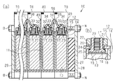
- (A) is a perspective view of the battery module which concerns on one Embodiment of this invention
- (b) is a fragmentary perspective view which expands and shows a part of battery module.
- (A) is sectional drawing of a battery module
- (b) is a fragmentary sectional view which expands and shows the connection terminal of a battery cell.
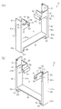
- (A) And (b) is a perspective view of a 1st battery holder.
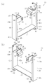
- (A) And (b) is a perspective view of a 2nd battery holder. Sectional drawing explaining an effect
- the battery module 10 includes a plurality of battery cells 11.
- Each of the plurality of battery cells 11 is juxtaposed in a state of being individually held by the battery holders 40 and 70.
- the first battery holder 40 and the second battery holder 70 are alternately arranged in parallel.
- Each battery holder 40, 70 is made of an insulating resin.
- Each battery cell 11 is arranged in parallel so that connection terminals 17 having different polarities are adjacent to each other in the direction in which the battery cells 11 are arranged.
- “parallel arrangement direction” indicates “parallel arrangement direction of battery cells 11”.
- Connection terminals 17 of adjacent battery cells 11 are alternately connected by bus bars 30. Thereby, the battery cells 11 are connected in series.
- the battery cells 11 held by the battery holders 40 and 70 are sandwiched between a first end plate 28 and a second end plate 29 provided at both ends in the juxtaposed direction.
- Bolts B are inserted through the second end plate 29 toward the first end plate 28.
- the battery cells 11 held by the battery holders 40 and 70 are connected to the first end plate 28, the second end plate 29, and the like. It is pinched by.
- a plate-like elastic member 27 is provided between the first end plate 28 and the battery cell 11 adjacent to the first end plate 28.
- the battery cell 11 has a case 12.
- An electrode assembly 13 is accommodated in the case 12.
- the case 12 includes a bottomed cylindrical main body 14 that houses the electrode assembly 13 and a lid 15 that closes an opening of the main body 14.
- the electrode assembly 13 is configured by laminating a plurality of positive and negative electrodes.
- the lid 15 is provided with two through holes 16.
- One connection terminal 17 protrudes from each through hole 16 one by one.
- the two connection terminals 17 are a positive terminal and a negative terminal.
- “projection direction” indicates “direction in which the connection terminal 17 projects from the case 12”.
- the connection terminal 17 has a base 18 disposed in the case 12.
- the base 18 is connected to the electrode assembly 13 via the conductive member 19.
- a cylindrical shaft portion 20 extends from the base portion 18.
- the shaft portion 20 protrudes from the through hole 16 to the outside of the case 12.
- the shaft portion 20 has a male screw 21 on the outer peripheral surface of the portion protruding outside the case 12.
- the shaft portion 20 has a screw hole 23 extending from the tip protruding out of the case 12 toward the base portion 18.
- a female screw is formed on the inner peripheral surface of the screw hole 23.
- a resin insulating ring 24 that insulates the connection terminal 17 and the lid 15 is interposed between the inner peripheral surface of the through-hole 16 and the shaft portion 20 and between the nut 22 and the lid 15.
- An O-ring 25 is provided on the outer peripheral surface of the base end of the shaft portion 20. The O-ring 25 is interposed between the base portion 18 and the lid 15 and insulates the connection terminal 17 and the lid 15.
- the bus bar 30 has a mountain-shaped bent portion 31.
- the bent portion 31 is formed by bending the central portion of the metal plate so as to protrude in the thickness direction.
- the bus bar 30 has flat connection portions 32 on both sides of the bent portion 31.
- the connecting portion 32 is provided with a through hole 33 that penetrates in the thickness direction.
- the bus bar 30 is fixed to the connection terminal 17 by screwing a screw 34 inserted through the through hole 33 into the screw hole 23 of the connection terminal 17.
- the first battery holder 40 has a rectangular flat plate-shaped first covering wall 41.
- a second covering wall 42 is provided at one of the longitudinal ends of the first covering wall 41, and a third covering wall 43 is provided at the other end.
- the second covering wall 42 and the third covering wall 43 are both formed in a rectangular flat plate shape and extend in the thickness direction of the first covering wall 41.
- a region surrounded by the first covering wall 41, the second covering wall 42, and the third covering wall 43 forms an accommodating portion S in which the battery cell 11 is accommodated.
- a first terminal accommodating portion 44 is provided on the surface of the second covering wall 42 that defines the accommodating portion S.
- the first terminal accommodating portion 44 is formed in a U shape so as to open in the lateral direction of the second covering wall 42.
- a first standing wall 48 extends upward from the first terminal accommodating portion 44.
- the first standing wall 48 has a protruding wall 49 that extends in a direction opposite to the second covering wall 42 and the third covering wall 43.
- the protruding wall 49 is provided continuously to the first end portion 42 a in the short direction of the second covering wall 42.
- a side wall 50 extends from the protruding wall 49 along the first terminal accommodating portion 44.
- the second terminal accommodating portion 51 is also provided on the surface of the third covering wall 43 that partitions the accommodating portion S.
- the second terminal accommodating portion 51 is also formed in a U shape so as to open in the lateral direction of the third covering wall 43.
- the second terminal accommodating portion 51 has the same shape as the first terminal accommodating portion 44.
- a second standing wall 55 extends upward from the second terminal accommodating portion 51.
- the second standing wall 55 has a connection wall 56 extending in the opposing direction of the second covering wall 42 and the third covering wall 43.
- the connection wall 56 is provided continuously to the first end portion 43 a in the short direction of the third covering wall 43.
- the height dimension of the connection wall 56 from the second terminal accommodating portion 51 is smaller than the height dimension of the protruding wall 49 from the first terminal accommodating portion 44.
- the connection wall 56 is provided with a pair of partition walls 60 extending upward from both ends of the connection wall 56.
- a notch 58 is formed between the pair of partition walls 60.
- a side wall 57 extends from the connection wall
- the first and second terminal accommodating portions 44 and 51 are respectively provided with columnar column portions 61.
- the column portion 61 has an axis extending in the short direction of the respective covering walls 42 and 43.
- the column portion 61 is provided with an insertion hole 62.
- the insertion hole 62 penetrates the column part 61 in the axial direction.
- the second covering wall 42 and the third covering wall 43 have a rectangular flat plate-like extending wall 63 at the first end portions 42b and 43b in the longitudinal direction thereof.
- the extending wall 63 is provided continuously to the second and third covering walls 42 and 43, and extends in the longitudinal direction of the second and third covering walls 42 and 43.
- the second covering wall 42 and the third covering wall 43 have columnar leg portions 64 at the second end portions 42c and 43c in the longitudinal direction thereof.
- the leg portion 64 has an axis extending in the short direction of the covering walls 42 and 43.
- the leg portion 64 is provided with an insertion hole 65.
- the insertion hole 65 penetrates the leg portion 64 in the axial direction.
- the second battery holder 70 has the same configuration as the first battery holder 40 except for the positions of the first standing wall 48 and the second standing wall 55. have. For this reason, the same code
- the positions of the first standing wall 48 and the second standing wall 55 of the second battery holder 70 are opposite to those of the first battery holder 40.
- the first standing wall 48 of the second battery holder 70 is provided in the second terminal accommodating portion 51 provided continuously with the third covering wall 43.
- the second standing wall 55 of the second battery holder 70 is provided in the first terminal accommodating portion 44 provided continuously with the second covering wall 42.
- the plurality of battery cells 11 are juxtaposed in a state of being held by the battery holders 40 and 70.
- a projecting wall 49, a connection wall 56, and a partition wall 60 are disposed between the connection terminals 17 adjacent in the direction in which the battery cells 11 are arranged side by side.
- the protruding wall 49, the connecting wall 56, and the partition wall 60 protrude in the protruding direction from the connecting terminal 17.
- the bus bar 30 connects the connection terminals 17 adjacent to each other in the juxtaposition direction by straddling the connection wall 56 with the bent portion 31.
- the pair of partition walls 60 of the connection wall 56 are disposed so as to sandwich the bent portion 31 straddling the connection wall 56 from both sides.
- the top of the bent portion 31 is disposed in the notch 58 between the pair of partition walls 60. That is, the pair of partition walls 60 partition the notch 58 that is the installation position of the bus bar 30 with the bent portion 31 sandwiched between the partition walls 60. Therefore, the connection wall 56 and the partition wall 60 are provided between the adjacent connection terminals 17 connected to each other by the bus bar 30.
- protruding walls 49 are arranged between the bus bars 30 adjacent in the juxtaposed direction. That is, the protruding wall 49 is disposed between the adjacent connection terminals 17 that are not connected to each other by the bus bar 30, in other words, between the adjacent connection terminals 17 to which different bus bars 30 are connected.
- the protruding wall 49 protrudes in the protruding direction from the bent portion 31 of the bus bar 30. Specifically, the protruding wall 49 protrudes in the protruding direction from the surface facing the battery cell 11 at the top of the bent portion 31. Accordingly, the protruding length of the bent portion 31 of the bus bar 30 is set to a dimension that straddles the connecting wall 56 but does not straddle the protruding wall 49.
- the battery cell 11 As the battery cell 11 is used, a film is formed on the surface of the electrode. As the thickness of the coating increases, the battery cell 11 expands and the distance between the connection terminals 17 adjacent in the juxtaposed direction increases. Then, the stress applied to the bus bar 30 increases, and the inclination of the bent portion 31 becomes gentle. That is, the thickness, thickness, inclination angle, and the like of the bent portion 31 are set such that the battery cell 11 can be extended in the juxtaposition direction when the battery cell 11 expands. As the bent portion 31 is deformed as described above, the stress applied to the bus bar 30 is reduced.
- the expansion limit which can charge / discharge the battery cell 11 appropriately is calculated
- the protruding length of the bent portion 31 of the bus bar 30 is set so that the bent portion 31 and the connection wall 56 do not contact when the battery cell 11 reaches the expansion limit.
- a difference between the first distance and the second distance is obtained, and a shortened length, which is a length that the bent portion 31 shortens in the protruding direction when the distance between the connecting portions 32 increases by the difference, is obtained.
- the protrusion length of the bending part 31 is set so that the separation distance of the bending part 31 and the connection wall 56 may become larger than said shortening length at the time of manufacture of the battery module 10. FIG. By setting as described above, even when the battery cell 11 expands to the expansion limit, the bent portion 31 does not contact the connection wall 56.
- the elastic member 27 is provided between the first end plate 28 and the battery cell 11 adjacent to the first end plate 28.
- the elastic member 27 can absorb the increase in load applied to the end plates 28 and 29 due to the expansion of the battery cell 11 by elastically deforming and contracting.
- a protruding wall 49 is provided between the bus bars 30 adjacent in the juxtaposed direction. For this reason, it can suppress that the battery cell 11 is connected in the part which is not intended by the electrically-conductive member. Therefore, since the short circuit of the battery cell 11 is suppressed, damage to the battery cell 11 can be suppressed.
- the bus bar 30 is provided with a bent portion 31 that protrudes in a direction intersecting the juxtaposed direction. When the battery cell 11 expands and stress is applied to the bus bar 30, the bent portion 31 is deformed, so that the bus bar 30 extends in the juxtaposition direction. Thereby, the stress applied to the bus bar 30 is reduced.
- connection portion 32 is difficult to be separated from the connection terminal 17. Therefore, an increase in contact resistance between the bus bar 30 and the connection terminal 17 is suppressed.
- deformation of the bent portion 31 reduces the stress applied to the bus bar 30 due to the expansion of the battery cell 11, so that the bus bar 30 is also prevented from being damaged. Therefore, the connection state of the battery cells 11 by the bus bar 30 can be maintained satisfactorily.
- connection wall 56 is provided between adjacent connection terminals 17 connected by the bus bar 30.
- the connection wall 56 protrudes in the protruding direction from the connection terminal 17. For this reason, it can suppress that the connection terminal 17 adjacent by the foreign material different from the bus-bar 30 is connected.
- a pair of partition walls 60 protrude from the connection wall 56 so as to sandwich the bent portion 31 of the bus bar 30. In this case, since the installation position of the bus bar 30 is partitioned by the pair of partition walls 60, the bus bar 30 can be positioned.
- the protruding wall 49 is provided in each of the battery holders 40 and 70. For this reason, the protruding wall 49 can be easily provided between the bus bars 30 adjacent to each other in the direction in which the battery cells 11 are arranged simply by arranging the battery holders 40 and 70 holding the battery cells 11 in parallel.
- the protruding length of the bent portion 31 is set so that the bent portion 31 and the connection wall 56 do not contact even when the battery cell 11 expands. For this reason, it can suppress that the bending part 31 and the connection wall 56 contact, and force is added to the bus bar 30, and the contact resistance of the connection terminal 17 and the bus bar 30 increases.
- An elastic member 27 is provided between the first end plate 28 and the battery cell 11 adjacent to the first end plate 28.
- the elastic member 27 can absorb the expansion of the battery cell 11 by being elastically deformed and contracted. For this reason, the load added to the 1st end plate 28 and the 2nd end plate 29 becomes small, and it can control that battery cell 11 expands and each end plates 28 and 29 are damaged.
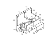
- the bus bar 30 may have a bent portion 80 that protrudes in a direction different from the protruding direction.
- the connection wall 81 is provided with a notch 82 through which the bent portion 80 is inserted so as to penetrate in the thickness direction of the connection wall 81.
- protrusion wall 49 should just protrude in the protrusion direction rather than the connection terminal 17, and does not need to protrude in the protrusion direction rather than the bending part 31.
- FIG. -Connection wall 56 may be omitted.
- the partition wall 60 that sandwiches the bent portion 31 may be omitted from the connection wall 56.
- the protruding wall 49 may be provided on a member different from the battery holders 40 and 70.
- a protruding wall may be provided on the insulating ring 24 of the battery cell 11.
- a protruding wall may be provided on an insulating plate interposed between adjacent battery cells 11.
- the bent portion 31 may contact the connection wall 56 when the battery cell 11 expands.
- -Battery holders 40 and 70 may be omitted.
- the protruding wall 49 may be provided on a member different from the battery holders 40 and 70.
- the elastic member 27 may be omitted.
Landscapes
- Chemical & Material Sciences (AREA)
- Chemical Kinetics & Catalysis (AREA)
- Electrochemistry (AREA)
- General Chemical & Material Sciences (AREA)
- Connection Of Batteries Or Terminals (AREA)
- Battery Mounting, Suspending (AREA)
Priority Applications (3)
| Application Number | Priority Date | Filing Date | Title |
|---|---|---|---|
| US15/507,119 US10177352B2 (en) | 2014-09-03 | 2015-08-10 | Battery module |
| DE112015004027.7T DE112015004027T5 (de) | 2014-09-03 | 2015-08-10 | Batteriemodul |
| CN201580045178.0A CN106575729B (zh) | 2014-09-03 | 2015-08-10 | 电池模块 |
Applications Claiming Priority (2)
| Application Number | Priority Date | Filing Date | Title |
|---|---|---|---|
| JP2014-179493 | 2014-09-03 | ||
| JP2014179493A JP6327072B2 (ja) | 2014-09-03 | 2014-09-03 | 電池モジュール |
Publications (1)
| Publication Number | Publication Date |
|---|---|
| WO2016035518A1 true WO2016035518A1 (ja) | 2016-03-10 |
Family
ID=55439585
Family Applications (1)
| Application Number | Title | Priority Date | Filing Date |
|---|---|---|---|
| PCT/JP2015/072691 Ceased WO2016035518A1 (ja) | 2014-09-03 | 2015-08-10 | 電池モジュール |
Country Status (5)
| Country | Link |
|---|---|
| US (1) | US10177352B2 (enExample) |
| JP (1) | JP6327072B2 (enExample) |
| CN (1) | CN106575729B (enExample) |
| DE (1) | DE112015004027T5 (enExample) |
| WO (1) | WO2016035518A1 (enExample) |
Families Citing this family (11)
| Publication number | Priority date | Publication date | Assignee | Title |
|---|---|---|---|---|
| JP6685760B2 (ja) | 2016-02-19 | 2020-04-22 | 株式会社Gsユアサ | 蓄電装置 |
| JP6946837B2 (ja) * | 2017-08-10 | 2021-10-13 | 株式会社豊田自動織機 | 電池パック |
| US10581041B2 (en) * | 2017-10-24 | 2020-03-03 | Ford Global Technologies, Llc | Battery array plate assembly with pressure retention pad |
| CN113795976B (zh) * | 2019-05-22 | 2023-08-22 | 三洋电机株式会社 | 汇流条板 |
| JP7132179B2 (ja) * | 2019-06-18 | 2022-09-06 | 矢崎総業株式会社 | バスバーモジュール |
| JP7132178B2 (ja) * | 2019-06-18 | 2022-09-06 | 矢崎総業株式会社 | バスバーモジュール |
| KR102769904B1 (ko) * | 2019-08-07 | 2025-02-17 | 주식회사 엘지에너지솔루션 | 배터리 모듈들의 기계적, 전기적 고정구조를 통합한 배터리 팩 |
| KR20210086090A (ko) * | 2019-12-31 | 2021-07-08 | 삼성에스디아이 주식회사 | 배터리 팩 |
| CN113794017B (zh) * | 2021-09-16 | 2023-08-04 | 深圳市壹加智慧科技有限公司 | 房车电池 |
| EP4239773B1 (en) * | 2022-01-14 | 2025-11-26 | Contemporary Amperex Technology (Hong Kong) Limited | Battery, power consuming device, method for preparing battery and device for preparing battery |
| KR20240121613A (ko) * | 2023-02-02 | 2024-08-09 | 삼성에스디아이 주식회사 | 이차전지 팩 |
Citations (5)
| Publication number | Priority date | Publication date | Assignee | Title |
|---|---|---|---|---|
| JP2004095380A (ja) * | 2002-08-30 | 2004-03-25 | Yazaki Corp | バッテリ接続プレート |
| JP2011076936A (ja) * | 2009-09-30 | 2011-04-14 | Toshiba Corp | 組電池およびこれを備えた二次電池装置 |
| JP2011210710A (ja) * | 2010-03-12 | 2011-10-20 | Autonetworks Technologies Ltd | 電池モジュール |
| JP2012022895A (ja) * | 2010-07-14 | 2012-02-02 | Toshiba Corp | 二次電池装置 |
| US20150171405A1 (en) * | 2013-12-17 | 2015-06-18 | Samsung Sdi Co., Ltd. | Battery module |
Family Cites Families (8)
| Publication number | Priority date | Publication date | Assignee | Title |
|---|---|---|---|---|
| JP3990960B2 (ja) * | 2002-08-30 | 2007-10-17 | 矢崎総業株式会社 | バッテリ接続プレートおよびその取付構造 |
| US20070087266A1 (en) * | 2005-10-18 | 2007-04-19 | Debbi Bourke | Modular battery system |
| JP5465440B2 (ja) * | 2009-01-28 | 2014-04-09 | 三洋電機株式会社 | 組電池 |
| JP5658450B2 (ja) * | 2009-11-12 | 2015-01-28 | 川崎重工業株式会社 | 電池システム |
| CN102117930B (zh) * | 2010-01-05 | 2015-09-16 | 三星Sdi株式会社 | 电池组 |
| US20110293994A1 (en) * | 2010-05-27 | 2011-12-01 | Gm Global Technology Operations Llc. | Battery pack assembly using clad electrical connections |
| JP2014060111A (ja) | 2012-09-19 | 2014-04-03 | Nissan Motor Co Ltd | 組電池 |
| JP5733332B2 (ja) * | 2013-02-13 | 2015-06-10 | 株式会社豊田自動織機 | 電池モジュール |
-
2014
- 2014-09-03 JP JP2014179493A patent/JP6327072B2/ja not_active Expired - Fee Related
-
2015
- 2015-08-10 WO PCT/JP2015/072691 patent/WO2016035518A1/ja not_active Ceased
- 2015-08-10 CN CN201580045178.0A patent/CN106575729B/zh not_active Expired - Fee Related
- 2015-08-10 DE DE112015004027.7T patent/DE112015004027T5/de not_active Withdrawn
- 2015-08-10 US US15/507,119 patent/US10177352B2/en active Active
Patent Citations (5)
| Publication number | Priority date | Publication date | Assignee | Title |
|---|---|---|---|---|
| JP2004095380A (ja) * | 2002-08-30 | 2004-03-25 | Yazaki Corp | バッテリ接続プレート |
| JP2011076936A (ja) * | 2009-09-30 | 2011-04-14 | Toshiba Corp | 組電池およびこれを備えた二次電池装置 |
| JP2011210710A (ja) * | 2010-03-12 | 2011-10-20 | Autonetworks Technologies Ltd | 電池モジュール |
| JP2012022895A (ja) * | 2010-07-14 | 2012-02-02 | Toshiba Corp | 二次電池装置 |
| US20150171405A1 (en) * | 2013-12-17 | 2015-06-18 | Samsung Sdi Co., Ltd. | Battery module |
Also Published As
| Publication number | Publication date |
|---|---|
| US10177352B2 (en) | 2019-01-08 |
| JP2016054063A (ja) | 2016-04-14 |
| DE112015004027T5 (de) | 2017-05-18 |
| CN106575729A (zh) | 2017-04-19 |
| JP6327072B2 (ja) | 2018-05-23 |
| US20170288183A1 (en) | 2017-10-05 |
| CN106575729B (zh) | 2019-02-22 |
Similar Documents
| Publication | Publication Date | Title |
|---|---|---|
| WO2016035518A1 (ja) | 電池モジュール | |
| JP6281398B2 (ja) | 電池モジュール | |
| US10388934B2 (en) | Battery module and method for manufacturing battery module | |
| US9979003B2 (en) | Bus bar including two conductive concave portions and battery module | |
| JP6252776B2 (ja) | 電池モジュール | |
| CN109155385B (zh) | 汇流排组装结构和电池模块 | |
| KR20170042587A (ko) | 배터리 모듈용 리셉터클, 및 상기 유형의 리셉터클을 포함하는 배터리 모듈 | |
| US20200013997A1 (en) | Battery pack | |
| JP6409345B2 (ja) | 電池モジュール及び電池パック | |
| JP6421497B2 (ja) | 電池モジュール | |
| JP2011253779A (ja) | 組電池 | |
| JP6398078B2 (ja) | 蓄電ユニット | |
| JP6488700B2 (ja) | 電池モジュール及び電池モジュールの製造方法 | |
| JP7134626B2 (ja) | 蓄電装置 | |
| JP6794709B2 (ja) | 電池モジュール | |
| WO2015170581A1 (ja) | 電池モジュール | |
| JP6233242B2 (ja) | 電池モジュール | |
| JP2015172411A (ja) | 締結部材 | |
| JP6337695B2 (ja) | 電池パック | |
| JP6233076B2 (ja) | 電池モジュール | |
| WO2016194545A1 (ja) | 電池パック | |
| JP6344148B2 (ja) | 電池パック | |
| JP2020030915A (ja) | 蓄電装置 | |
| JP2015162389A (ja) | 電池体 | |
| WO2016042855A1 (ja) | ハーネス取付構造及び電池パック |
Legal Events
| Date | Code | Title | Description |
|---|---|---|---|
| 121 | Ep: the epo has been informed by wipo that ep was designated in this application |
Ref document number: 15837286 Country of ref document: EP Kind code of ref document: A1 |
|
| WWE | Wipo information: entry into national phase |
Ref document number: 15507119 Country of ref document: US |
|
| WWE | Wipo information: entry into national phase |
Ref document number: 112015004027 Country of ref document: DE |
|
| 122 | Ep: pct application non-entry in european phase |
Ref document number: 15837286 Country of ref document: EP Kind code of ref document: A1 |