WO2016031411A1 - メカニカルシール - Google Patents
メカニカルシール Download PDFInfo
- Publication number
- WO2016031411A1 WO2016031411A1 PCT/JP2015/070103 JP2015070103W WO2016031411A1 WO 2016031411 A1 WO2016031411 A1 WO 2016031411A1 JP 2015070103 W JP2015070103 W JP 2015070103W WO 2016031411 A1 WO2016031411 A1 WO 2016031411A1
- Authority
- WO
- WIPO (PCT)
- Prior art keywords
- rotating
- notch
- rotation
- sealing ring
- mechanical seal
- Prior art date
Links
Images


Classifications
-
- F—MECHANICAL ENGINEERING; LIGHTING; HEATING; WEAPONS; BLASTING
- F16—ENGINEERING ELEMENTS AND UNITS; GENERAL MEASURES FOR PRODUCING AND MAINTAINING EFFECTIVE FUNCTIONING OF MACHINES OR INSTALLATIONS; THERMAL INSULATION IN GENERAL
- F16J—PISTONS; CYLINDERS; SEALINGS
- F16J15/00—Sealings
- F16J15/16—Sealings between relatively-moving surfaces
- F16J15/34—Sealings between relatively-moving surfaces with slip-ring pressed against a more or less radial face on one member
- F16J15/36—Sealings between relatively-moving surfaces with slip-ring pressed against a more or less radial face on one member connected by a diaphragm or bellow to the other member
-
- F—MECHANICAL ENGINEERING; LIGHTING; HEATING; WEAPONS; BLASTING
- F16—ENGINEERING ELEMENTS AND UNITS; GENERAL MEASURES FOR PRODUCING AND MAINTAINING EFFECTIVE FUNCTIONING OF MACHINES OR INSTALLATIONS; THERMAL INSULATION IN GENERAL
- F16J—PISTONS; CYLINDERS; SEALINGS
- F16J15/00—Sealings
- F16J15/16—Sealings between relatively-moving surfaces
- F16J15/32—Sealings between relatively-moving surfaces with elastic sealings, e.g. O-rings
- F16J15/3204—Sealings between relatively-moving surfaces with elastic sealings, e.g. O-rings with at least one lip
-
- F—MECHANICAL ENGINEERING; LIGHTING; HEATING; WEAPONS; BLASTING
- F16—ENGINEERING ELEMENTS AND UNITS; GENERAL MEASURES FOR PRODUCING AND MAINTAINING EFFECTIVE FUNCTIONING OF MACHINES OR INSTALLATIONS; THERMAL INSULATION IN GENERAL
- F16J—PISTONS; CYLINDERS; SEALINGS
- F16J15/00—Sealings
- F16J15/16—Sealings between relatively-moving surfaces
- F16J15/34—Sealings between relatively-moving surfaces with slip-ring pressed against a more or less radial face on one member
- F16J15/3464—Mounting of the seal
- F16J15/348—Pre-assembled seals, e.g. cartridge seals
-
- F—MECHANICAL ENGINEERING; LIGHTING; HEATING; WEAPONS; BLASTING
- F16—ENGINEERING ELEMENTS AND UNITS; GENERAL MEASURES FOR PRODUCING AND MAINTAINING EFFECTIVE FUNCTIONING OF MACHINES OR INSTALLATIONS; THERMAL INSULATION IN GENERAL
- F16J—PISTONS; CYLINDERS; SEALINGS
- F16J15/00—Sealings
- F16J15/16—Sealings between relatively-moving surfaces
- F16J15/34—Sealings between relatively-moving surfaces with slip-ring pressed against a more or less radial face on one member
- F16J15/38—Sealings between relatively-moving surfaces with slip-ring pressed against a more or less radial face on one member sealed by a packing
-
- Y—GENERAL TAGGING OF NEW TECHNOLOGICAL DEVELOPMENTS; GENERAL TAGGING OF CROSS-SECTIONAL TECHNOLOGIES SPANNING OVER SEVERAL SECTIONS OF THE IPC; TECHNICAL SUBJECTS COVERED BY FORMER USPC CROSS-REFERENCE ART COLLECTIONS [XRACs] AND DIGESTS
- Y10—TECHNICAL SUBJECTS COVERED BY FORMER USPC
- Y10S—TECHNICAL SUBJECTS COVERED BY FORMER USPC CROSS-REFERENCE ART COLLECTIONS [XRACs] AND DIGESTS
- Y10S277/00—Seal for a joint or juncture
- Y10S277/91—O-ring seal
Definitions
- the present invention relates to a mechanical seal used for sealing a rotary device such as a submersible pump and a land-use general-purpose pump, and more specifically, a spring that applies a sealing surface pressure on a sliding surface of a fixed-side sealing ring and a rotating-side sealing ring. Relates to a mechanical seal on the rotating side.
- a fixed-side sealing ring 32 is formed in the opening of the shaft hole 51 of the housing 30 as a kind of mechanical seal in which a spring for applying a sealing surface pressure exists on the rotation side.
- the rotary side sealing ring 33 which is fitted in the recess 52 in an airtight manner via the cup gasket 31 while being axially movable on the outer periphery of the rotary shaft 50 is a coil spring 41 backed up by a collar 40.
- a sealing sliding surface S is formed by being pressed against the fixed-side sealing ring 32 by an axial urging force, and a bellows 45 is provided as an operating shaft packing between the outer peripheral surface of the rotating shaft 50 and the back surface 33a of the rotating-side sealing ring 33.
- a bellows 45 hereinafter referred to as “prior art”. For example, see Patent Documents 1 and 2). .).
- the front neck portion 45a of the bellows 45 having a sickle-shaped cross section is fixed to the inner side of the back surface portion 46a of the metal case 46 fitted to the outer periphery of the rotation-side sealing ring 33,
- the inner cylindrical portion 45b of the bellows 45 is in close contact with the back surface 33a of the rotation-side sealing ring 33, and is tightened by a metal drive ring 47 fitted to the outer peripheral surface thereof. Is crimped with an appropriate tightening allowance.
- a protrusion 46c extending in the axial direction is provided on the inner diameter side of the back surface portion 46a of the case 46, and the protrusion 46c is loosely fitted with an axially-notched groove 47a formed on the outer peripheral surface of the drive ring 47.
- a depression 46e formed in the outer diameter cylindrical portion 46d of 46 is fitted in a recess 33b formed on the outer peripheral surface of the rotation-side sealing ring 33. That is, the driving force from the rotary shaft 50 is transmitted to the rotation-side sealing ring 33 through the inner cylindrical portion 45b of the bellows 45, the cutout groove 47a of the drive ring 47, the protrusion 46c of the case 46, and the recessed portion 46e of the case 46. , Rotate integrally with the rotary shaft 50.
- the following two methods are known as means for integrating the rotary side sealing ring 33 with the rotary side member such as the bellows 45.
- First means As shown in FIGS. 8B and 8C, the tip of the rotation side sealing ring 33 of the outer diameter cylindrical portion 46d of the case 46 is crimped to the inner diameter side to form a bent portion 46f. The surface 33c of the rotation-side sealing ring 33 is wrapped with the bent portion 46f.
- the bent portion 46f is originally not in contact with the surface 33c of the rotation-side sealing ring 33.
- the crimping jig, the crimping conditions, and the rotation-side component (rotation-side) Depending on the finished dimensions of the sealing ring 33, the bellows 45, the drive ring 47 and the case 46), it is too caulked as shown in FIG. 8B, or the caulking is normal as shown in FIG. Due to the fact that 46f is in strong contact with the surface 33c of the rotation-side sealing ring 33, there is a problem that distortion and cracks occur in the rotation-side sealing ring 33.
- non-drying adhesive is apply
- the present invention has been made to solve the above-described problems of the prior art, and without using a caulking means and an adhesive means using an adhesive, the rotation side sealing ring can be rotated by a bellows or the like other than the rotation side sealing ring. It aims at providing the mechanical seal which can be integrated with the structural member of the side.
- a mechanical seal of the present invention is a mechanical seal that is firstly attached to a shaft sealing portion formed between a housing and a rotating shaft, and seals between the housing and the rotating shaft.
- a bellows that seals between the rotary seal ring axially urged by the biasing member and the outer peripheral surface of the rotary shaft, a case fitted on the rotary seal ring and the outer periphery of the bellows, and the bellows
- the mechanical seal having a drive ring for tightening the rotating shaft, a plurality of notch grooves penetrating in the axial direction are provided in the outer peripheral portion of the rotating seal ring, and the side surface on the sealing sliding surface side of the rotating seal ring Is provided with a non-rotating cutout portion extending in the circumferential direction from the cutout groove, and an inner diameter capable of passing through the cutout groove facing the cutout groove at an end of the case on the rotation side sealing ring side.
- the mechanical seal of the present invention is secondly characterized in that, in the first feature, a bellows sealing surface is formed on a side of the bellows that contacts the back surface of the rotation-side sealing ring, and the bellows sealing surface or the vicinity thereof is formed. Is provided with a plurality of protrusions protruding in the circumferential direction from the bellows sealing surface to the rotation side sealing ring side, and the protrusions are formed on the rotation side when the rotation side sealing ring and the bellows are integrated.
- the sealing ring By pushing the sealing ring in the axial direction, the back surface of the rotating side sealing ring and the bellows sealing surface are brought into a non-contact state, and when the mechanical seal is mounted between the housing and the rotating shaft, it is elastically deformed. Thus, the back surface of the rotary side sealing ring and the bellows sealing surface are set to contact each other. According to this feature, the rotating side sealing ring is always pushed by the spring force of the protrusion, so that the rotating side sealing ring is displaced in the circumferential direction and is detached from other rotating side components even during transportation and handling. This can be prevented, and the rotation-side sealing ring can be reliably locked to the other rotation-side components.
- the dimensional relationship between the axial length from the inside of the back of the case to the back of the detent projection and the axial length from the inside of the back of the case to the side of the non-rotating notch of the rotary seal ring Manufacture is facilitated because there is no need to determine exactly. Further, the assembly can be facilitated, and it is possible to prevent occurrence of cracks in the side surface of the rotation stop notch, cracks in the rotation side sealing ring, and distortion of the sealing sliding surface due to forced insertion.
- the non-rotating notch is formed so as to extend from the notch groove to one side in the circumferential direction, and the back surface of the non-rotating convex
- the side surface of the non-rotating cutout portion that is in contact is characterized by being formed in parallel to a surface orthogonal to the rotation axis. According to this feature, it is possible to easily process the rotation stop notch.
- the mechanical seal of the present invention is, fourthly, in the first or second feature, the non-rotating notch is formed so as to extend from the notch groove to one side in the circumferential direction, and is in contact with the back surface of the non-rotating convex.
- the side surface of the non-rotating notch that is in contact is characterized by being inclined so as to become deeper toward the peripheral end. According to this feature, the non-rotating convex portion is not easily detached from the non-rotating notch portion.
- the non-rotating notch is formed so as to extend from the notch groove in one of the circumferential directions, and the back of the non-rotating convex is contacted.
- the side surface of the non-rotating notch that is in contact is characterized by being inclined so as to become shallower toward the peripheral end. According to this feature, the non-rotating convex portion can be easily fitted into the non-rotating notch portion, and both can be closely locked with each other in the relative rotation in the circumferential direction.
- the non-rotating notch portion is formed so as to extend from the notch groove to one side in the circumferential direction, and the back surface of the non-rotating convex portion is contacted.
- a side surface of the non-rotating cutout portion that is in contact is formed in parallel to a surface orthogonal to the rotation axis, and a concave portion that is recessed in the axial direction is formed in the vicinity of the peripheral end. According to this feature, the non-rotating convex portion is more difficult to separate from the non-rotating notch portion.
- the non-rotating notch portion is formed so as to extend in both the circumferential direction from the notch groove, and the back surface of the non-rotating convex portion is contacted.
- the side surface of the non-rotating notch that is in contact is formed in parallel to a surface orthogonal to the rotation axis. According to this feature, even when the rotation shaft rotates in either direction, the non-rotating convex portion is not easily detached from the non-rotating notch portion.
- the non-rotating notch is formed so as to extend in both the circumferential direction from the notch groove, and the back of the non-rotating convex is contacted.
- the side surface of the non-rotating notch that is in contact is characterized by being inclined so as to become deeper toward the peripheral end. According to this feature, even when the rotation shaft rotates in either direction, the non-rotating convex portion is more difficult to be detached from the non-rotating notch portion.
- the non-rotating notch is formed so as to extend in both the circumferential direction from the notch groove, and the back of the non-rotating convex is
- the side surface of the non-rotating notch that is in contact is characterized by being inclined so as to become shallower toward the peripheral end. According to this feature, even in a type in which the rotating shaft rotates in either direction, the non-rotating convex portion is easy to fit into the non-rotating notch portion, and the two are closely related with each other in the circumferential rotation. Stopped.
- the mechanical seal according to the tenth aspect of the present invention is characterized in that, in any of the third to ninth features, the bottom surface of the non-rotating notch is formed in parallel with the outer peripheral surface of the rotation-side sealing ring. It is said. According to this feature, the rotation stop notch can be easily processed.
- the mechanical seal of the present invention is formed such that the bottom surface of the non-rotating cutout portion becomes shallower toward the circumferential end. It is characterized by having. According to this feature, both of the non-rotating convex portion and the non-rotating notch portion are closely locked together with the relative rotation in the circumferential direction.
- the present invention has the following excellent effects. (1) Since no caulking means or non-drying adhesive means is used, the sealing fluid leaks due to the occurrence of distortion and cracks in the rotary seal ring 5 due to the caulking means and uneven application of the non-drying adhesive, Adhesion of non-drying adhesive to the sealing sliding surface can be eliminated, the life of the rotating side seal ring is improved, the reliability of integration of the rotating side components is increased, and the sealing property of the sealing sliding surface is maintained. can do.
- the rotation-side seal ring Since a plurality of protrusions are provided in the circumferential direction, the rotation-side seal ring is always pushed by the spring force of the protrusions. It is possible to prevent the rotation-side component from being detached, and the rotation-side sealing ring can be reliably locked to another rotation-side component.
- the dimensional relationship between the axial length from the inside of the back of the case to the back of the detent projection and the axial length from the inside of the back of the case to the side of the non-rotating notch of the rotary seal ring Manufacture is facilitated because there is no need to determine exactly. Further, the assembly can be facilitated, and it is possible to prevent occurrence of cracks in the side surface of the rotation stop notch, cracks in the rotation side sealing ring, and distortion of the sealing sliding surface due to forced insertion.
- the non-rotating notch is formed so as to extend from the notch groove to one side in the circumferential direction, and the side surface of the non-rotating notch that contacts the back surface of the non-rotating convex is formed parallel to the plane orthogonal to the rotation axis. By doing so, it is possible to facilitate the processing of the rotation stop notch.
- the non-rotating notch is formed so as to extend from the notch groove to one side in the circumferential direction, and the side surface of the non-rotating notch contacting the back surface of the non-rotating convex is inclined so as to become deeper toward the circumferential end. As a result, the non-rotating convex portion is difficult to separate from the non-rotating notch portion.
- the non-rotating notch is formed so as to extend from the notch groove to one side in the circumferential direction, and the side surface of the non-rotating notch contacting the back of the non-rotating convex is inclined so as to become shallower toward the peripheral end. By doing so, the non-rotating convex portion can be easily fitted into the non-rotating notch portion, and both can be closely locked with each other in the relative rotation in the circumferential direction.
- the non-rotating notch is formed so as to extend from the notch groove to one side in the circumferential direction, and the side surface of the non-rotating notch that is in contact with the back surface of the non-rotating convex is formed in parallel to the plane orthogonal to the rotation axis. In addition, since the concave portion that is recessed in the axial direction is formed in the vicinity of the peripheral end, the non-rotating convex portion is more difficult to separate from the non-rotating notch portion.
- the non-rotating notch is formed so as to extend in both the circumferential direction from the notch groove, and the side surface of the non-rotating notch that contacts the back surface of the non-rotating convex is formed in parallel to the plane orthogonal to the rotation axis. Therefore, even when the rotation shaft rotates in either direction, the non-rotating convex portion is not easily detached from the non-rotating notch portion.
- the non-rotating notch is formed so as to extend both in the circumferential direction from the notch groove, and the side surface of the non-rotating notch contacting the back surface of the non-rotating convex is inclined so as to become deeper toward the circumferential end.
- the non-rotating notch is formed so as to extend both in the circumferential direction from the notch groove, and the side surface of the non-rotating notch that contacts the back surface of the non-rotating convex is inclined so as to become shallower toward the peripheral end. Therefore, even in the type in which the rotating shaft rotates in either direction, the non-rotating convex portion can be easily fitted into the non-rotating notch portion, and both are intimately engaged with each other due to the relative rotation in the circumferential direction. Stopped.
- the bottom surface of the rotation stop notch is formed in parallel with the outer peripheral surface of the rotation-side sealing ring, the rotation stop notch can be easily processed.
- the bottom surface of the non-rotating notch is formed so that the depth becomes shallower toward the end in the circumferential direction, so that with the relative rotation in the circumferential direction of the non-rotating convex and the non-rotating notch Both are closely locked.
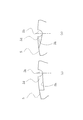
- FIG. 2 is a cross-sectional view taken along the line AA in FIG. 3A is an enlarged front view of the outer peripheral portion of the rotary side sealing ring of FIG. 2
- FIG. 3B is a plan view of FIG. 3A
- FIG. 3C is FIG.
- It is a top view which shows the various shapes of the rotation stop notch provided in the rotation side sealing ring of the mechanical seal which concerns on Example 1 of this invention.
- It is a front view which shows the various bottom face shapes of the rotation stop notch part in the mechanical seal which concerns on Embodiment 1 of this invention.
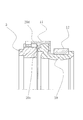
- FIG. 1 A mechanical seal according to Embodiment 1 of the present invention will be described with reference to FIGS. 1 to 5.
- the left side of the paper is the outside of the machine, and the right side is the inside of the machine.
- the mechanical seal shown in FIG. 1 is provided with a seal member such as a stationary seal ring 4 and a rotation seal ring 5 mounted on a shaft seal portion 3 formed between a housing 1 and a rotation shaft 2, and the housing 1 and the rotation shaft. 2 and a biasing member (coil spring 9) for applying a sealing surface pressure between the stationary seal ring 4 and the rotation-side seal ring 5 is present on the rotation side.
- a seal member such as a stationary seal ring 4 and a rotation seal ring 5 mounted on a shaft seal portion 3 formed between a housing 1 and a rotation shaft 2, and the housing 1 and the rotation shaft. 2 and a biasing member (coil spring 9) for applying a sealing surface pressure between the stationary seal ring 4 and the rotation-side seal ring 5 is present on the rotation side.
- the fixed-side sealing ring 4 is fitted in an airtight manner through a cup gasket 7 in a fitting recess 6 formed in the opening of the shaft sealing portion 3 of the housing 1.
- the rotation-side sealing ring 5 arranged on the outer periphery of the rotation shaft 2 so as to be axially movable is fixed to the fixed-side sealing ring 4 by the axial biasing force of the coil spring 9 backed up by the collar 8 fixed to the rotation shaft 2.
- a sealing sliding surface S is formed by the axial biasing force of the coil spring 9 backed up by the collar 8 fixed to the rotation shaft 2.
- a bellows 10 is interposed as an operating shaft packing between the outer peripheral surface of the rotating shaft 2 and the back surface 5a of the rotating side sealing ring 5, and the structure between the rotating side sealing ring 5 and the rotating shaft 2 is sealed with the bellows 10. It has become.
- the bellows 10 is formed of, for example, an elastic material such as a rubber material, and has a sickle neck in cross section.
- a tip neck portion 10a is a back portion of a metal case 11 fitted on the outer periphery of the rotation-side sealing ring 5. It is fixed inside 11a. Further, the distal neck portion 10 a is in close contact with the back surface 5 a of the rotation side sealing ring 5. Further, the inner cylindrical portion 10 b of the bellows 10 is fastened by a metal drive ring 12 fitted on the outer peripheral surface thereof, and is crimped to the outer peripheral surface of the rotating shaft 2 with an appropriate tightening allowance.
- a protrusion 11c extending in the axial direction toward the collar 8 is provided on the inner diameter side of the back surface portion 11a of the case 11, and this protrusion 11c is formed in an axially extending notch groove 12a formed on the outer peripheral surface of the drive ring 12. It comes to loose fit.
- a plurality of cutout grooves 5 b penetrating in the axial direction are provided on the outer peripheral portion of the rotation-side sealing ring 5.
- the cutout grooves 5b are provided in six equal distributions, but the present invention is not limited to this and may be two or more.
- the shape (refer FIG.2 and FIG.3 (a)) seen from the front of the notch groove 5b has comprised semicircle shape, it is not limited to this, For example, a rectangular shape may be sufficient.
- a non-rotating notch portion 5d is provided so as to extend in the circumferential direction from the notch groove 5b. Yes. The role and shape of the rotation stop notch 5d will be described in detail later.
- the end portion 11d of the case 11 shown in FIG. 1 on the rotating seal ring 5 side has a shape that can pass through the notch groove 5b at a position corresponding to the notch groove 5b, and bulges in the inner diameter direction.
- a stop projection 11e is provided (particularly, refer to FIG. 2).
- the detent protrusion 11e can also pass through the notch grooves 5b corresponding to the radial and circumferential positions of the notch grooves 5b. In this way, they are provided in a 6-spacing manner in a semicircular shape slightly smaller than the notch groove 5b.
- the length in the axial direction from the inside of the back surface portion 11a of the case 11 to the back surface 11f of the detent projection 11e is L1
- the free length in the axial direction of the front neck portion 10a of the bellows in a state where no pressing load is applied.
- a slight gap is formed between the back surface 11f of the non-rotating projection 11e and the side surface 5e of the non-rotating notch 5d.
- the rotation-side sealing ring 5 is transmitted with driving force from the rotary shaft 2 via the inner cylindrical portion 10b of the bellows 10, the cutout groove 12a of the drive ring 12, the protrusion 11c of the case 11, and the non-rotating convex portion 11e of the case 11. , Rotate integrally with the rotary shaft 2.
- an assembly including the rotation-side sealing ring 5, the bellows 10, the case 11, and the drive ring 12 may be referred to as a rotation-side component.
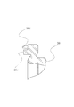
- FIG. 4 is a plan view of the outer peripheral surface of the rotation-side sealing ring 5 and shows various planar shapes of the rotation stop notch 5d.
- the non-rotating notch 5d is formed so as to extend from the notch groove 5b to one side in the circumferential direction, and the side surface 5e of the non-rotating notch that abuts the back surface 11f of the non-rotating convex 11e is the rotation shaft. It is formed in parallel to a plane orthogonal to. This example is easy to process and has an orthodox shape.
- the circumferential length R of the non-rotating notch 5d may be at least the same as the circumferential length of the non-rotating convex 11e.
- the non-rotating convex 11e is detached from the non-rotating notch 5d.
- the non-rotating notch 5d is formed so as to extend from the notch groove 5b to one side in the circumferential direction, and the side surface 5e of the non-rotating notch that abuts the back surface 11f of the non-rotating convex 11e is the rotation shaft. So that the non-rotating notch portion 5d becomes deeper toward the peripheral end (the side surface 5e of the non-rotating notch portion 5d faces the contact portion 5f of the non-rotating notch portion 5d). Inclined) In this example, there is an effect that the non-rotating convex portion 11e is difficult to be separated from the non-rotating notch portion 5d.
- the non-rotating notch 5d is formed so as to extend from the notch groove 5b to one side in the circumferential direction, and the side surface 5e of the non-rotating notch that abuts the back surface 11f of the non-rotating convex 11e is the rotation shaft. So that the non-rotating notch portion 5b becomes shallower toward the circumferential end (the side surface 5e of the non-rotating notch portion approaches the side surface 5c toward the contact portion 5f of the non-rotating notch portion). So that it is inclined.
- This example has an effect that the non-rotating convex portion 11e is easily fitted into the non-rotating notch portion 5d, and the two are closely locked together with the relative rotation of both in the circumferential direction.
- the non-rotating notch 5d is formed so as to extend from the notch groove 5b to one side in the circumferential direction, and the side surface 5e of the non-rotating notch that abuts the back surface 11f of the non-rotating convex 11e is the rotation shaft. Is formed in parallel with a surface orthogonal to the surface, and a concave portion is formed in the axial direction in the vicinity of the peripheral end. This example has an effect that the non-rotating convex portion 11e is more difficult to be separated from the non-rotating notch portion 5d.
- the non-rotating notch portion 5d is formed so as to extend both in the circumferential direction from the notch groove 5b, and the side surface 5e of the non-rotating notch portion contacting the back surface 11f of the non-rotating convex portion 11e is the rotation shaft. It is formed in parallel to a plane orthogonal to. This example has an effect that the non-rotating convex portion 11e is less likely to be detached from the non-rotating notch portion 5d even when the rotary shaft 2 rotates in either direction.
- the non-rotating notch 5d is formed so as to extend in both the circumferential direction from the notch groove 5b, and the side surface 5e of the non-rotating notch that abuts the back surface 11f of the non-rotating convex 11e is the rotating shaft. It is not parallel to the plane perpendicular to the surface, that is, it is inclined so as to become deeper toward the peripheral end. In this example, even when the rotating shaft 2 rotates in either direction, there is an effect that the non-rotating convex portion 11e is more difficult to separate from the non-rotating notch portion 5d.
- the non-rotating notch 5d is formed so as to extend both in the circumferential direction from the notch groove 5b, and the side surface 5e of the non-rotating notch that abuts the back surface 11f of the non-rotating convex 11e is a rotating shaft. It is not parallel to the plane orthogonal to the surface, that is, is inclined so as to become shallower toward the peripheral edge. In this example, even in the type in which the rotating shaft 2 rotates in either direction, the rotation preventing projection 11e can be easily fitted into the rotation stopping notch 5d, and the two are in close contact with each other in the circumferential rotation. There is an effect of being locked.
- FIG. 5 is a front view of the outer peripheral surface of the rotation-side sealing ring 5 and shows various bottom shapes of the rotation stop notch.
- the bottom surface 5 h of the rotation stop notch 5 d is formed in parallel with the outer peripheral surface of the rotation-side sealing ring 5. This example is easy to process and has an orthodox shape.
- the bottom surface 5h of the rotation stop notch 5d is formed so that the depth becomes shallower toward the end in the circumferential direction.
- the mechanical seal according to the first embodiment of the present invention has the following effects. (1) In fixing the rotation-side seal ring 5 in the integration of the rotation-side structural members that are assemblies of the rotation-side seal ring 5, the bellows 10, the case 11, and the drive ring 12, the rotation-preventing convex portion 11e of the case 11 is fixed. And the rotation-side sealing ring 5 are locked together by fitting with the non-rotating cutout 5d, and there is no need to use caulking means or non-drying adhesive means. It is possible to eliminate the occurrence of distortion and cracks in the sealing ring 5, leakage of the sealing fluid due to uneven application of the non-drying adhesive, and adhesion of the non-drying adhesive to the sealing sliding surface S.
- the life of the rotating side seal ring 5 can be improved, the reliability of the integration of the rotating side components can be increased, and the sealing performance of the sealing sliding surface S can be maintained.
- the shape of the non-rotating cutout 5d it is possible to prevent the rotation-side sealing ring 5 and the case 11 from being detached and to facilitate the fitting. Furthermore, the fitting state of both can be made close. Specifically, it is as follows.
- the non-rotating notch portion 5d is formed so as to extend from the notch groove 5b to one side in the circumferential direction, and the side surface 5e of the non-rotating notch portion that contacts the back surface 11f of the non-rotating convex portion 11e is a surface orthogonal to the rotation axis. Are not parallel to each other, that is, are inclined so as to be deeper toward the circumferential end, so that the non-rotating convex portion 11e is unlikely to be detached from the non-rotating notch portion 5d.
- the non-rotating notch portion 5d is formed to extend from the notch groove 5b to one side in the circumferential direction, and the side surface 5e of the non-rotating notch portion that contacts the back surface 11f of the non-rotating convex portion 11e is a surface orthogonal to the rotation axis.
- the detent projection 11e can be easily fitted into the detent cutout portion 5d, and both of them with relative rotation in the circumferential direction. Are closely locked.
- the non-rotating notch portion 5d is formed so as to extend from the notch groove 5b to one side in the circumferential direction, and the side surface 5e of the non-rotating notch portion that contacts the back surface 11f of the non-rotating convex portion 11e is a surface orthogonal to the rotation axis. Are formed in parallel to each other, and a recess recessed in the axial direction is formed in the vicinity of the peripheral end, so that the non-rotating convex portion 11e is further less likely to be detached from the non-rotating notch portion 5d.
- the non-rotating notch portion 5d is formed so as to extend both in the circumferential direction from the notch groove 5b, and the side surface 5e that abuts the back surface 11f of the non-rotating convex portion 11e is formed in parallel to the surface orthogonal to the rotation axis.
- the non-rotating notch 5d is formed so as to extend in both the circumferential direction from the notch groove 5b, and the side surface 5e of the non-rotating notch that contacts the back surface 11f of the non-rotating convex 11e is a surface orthogonal to the rotation axis. Is not parallel, that is, is inclined so as to become deeper toward the peripheral end, so that the non-rotating projection 11e is further detached from the non-rotating notch 5d even when the rotary shaft 2 rotates in both directions. Hard to do.
- the non-rotating notch portion 5d is formed so as to extend both in the circumferential direction from the notch groove 5b, and the side surface 5e of the non-rotating notch portion that contacts the back surface 11f of the non-rotating convex portion 11e is a surface orthogonal to the rotation axis.
- Non-parallel i.e., inclined so as to become shallower toward the peripheral edge, even in the type in which the rotating shaft 2 rotates in both directions, the non-rotating convex portion 11e can be easily fitted into the non-rotating notch portion 5d.
- both are closely latched with relative rotation of both circumferential directions.
- the bottom surface 5h of the non-rotating notch portion 5d is formed so that the depth becomes shallower toward the end portion in the circumferential direction, so that the circumferential direction of the non-rotating convex portion 11e and the non-rotating notch portion 5d is increased. The two are closely locked together with the relative rotation.
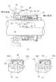
- the mechanical seal which concerns on Example 2 of this invention is demonstrated.
- the mechanical seal according to the second embodiment is different from the first embodiment in that a plurality of protrusions protruding toward the rotation-side sealing ring are provided on the side of the bellows that contacts the back surface of the rotation-side sealing ring.
- the other points are basically the same as those of the first embodiment, the same members as those of the first embodiment are denoted by the same reference numerals, and a duplicate description is omitted.
- the bellows 20 is formed of a rubber material, a bellows sealing surface 20c is formed on the side of the bellows 20 that contacts the back surface 5a of the rotating side sealing ring 5, and the bellows sealing surface 20c has a bellows on the outer diameter side.
- a plurality of protrusions 20d protruding from the sealing surface 20c toward the rotation-side sealing ring 5 are provided in the circumferential direction.
- the protrusion 20d pushes the rotation-side sealing ring 5 in the axial direction, so that the back surface 5a of the rotation-side sealing ring 5 and the bellows sealing surface 20c And has a spring function that can securely contact the side surface 5e of the non-rotating cutout portion 5d of the rotation-side sealing ring 5 and the back surface 11f of the non-rotating convex portion 11e of the case 11.
- the seal is mounted between the housing 1 and the rotary shaft 2, the back surface 5a of the rotary seal ring 5 and the bellows seal surface 20c are set in contact with each other by elastic deformation.
- the shape of the protrusion 20d is not particularly limited. Further, the place where the protrusion 20d is provided is not limited to the outer diameter side of the bellows sealing surface 20c, and may be any place near the bellows sealing surface 20c.
- the rotation-side sealing ring 5 is always pushed by the spring force of the protrusion 20d, so that the rotation-side sealing ring 5 is displaced in the circumferential direction during transportation and handling, and from other rotation-side components. Separation can be prevented, and the rotation-side sealing ring 5 can be reliably locked to the other rotation-side components.
- the length in the axial direction from the inner side of the back surface portion 11a of the case 11 to the back surface 11f of the detent projection 11e is L1
- the tip neck portion of the bellows depending on the completed state of the component dimensions of the rotating side component members
- a length obtained by adding the free length in the axial direction of 10a (the axial length in a state where no pressing load is applied) and the axial length from the back surface 5a of the rotation-side sealing ring 5 to the side surface 5e of the rotation notch When L2 is L2, L2> L1 or L2 ⁇ L1 may be satisfied.
- the tip neck 10a is deformed by the force when the bellows 10 is installed inside the case 11, and the back surface 11f of the non-rotating projection 11e of the case 11 and the non-rotating notch 5d of the rotation side sealing ring 5 are provided.
- the side surface 5e of the non-rotating notch portion is in contact with each other.
- the back surface 11f of the non-rotating convex portion 11e of the case 11 and the side surface 5e of the non-rotating notch portion of the non-rotating notch portion 5d of the rotating side sealing ring 5 are provided. Do not touch.
- Example 2 of this invention has the following effects. (1) Since the rotation-side sealing ring 5 is always pushed by the spring force of the protrusion 20d, the rotation-side sealing ring 5 is displaced in the circumferential direction and is detached from the other rotation-side components even during transportation and handling. This can prevent the rotation-side sealing ring 5 from being reliably locked to the other rotation-side components.
Abstract
Description
第1の手段:図8(b)及び(c)に示すように、ケース46の外径筒状部46dの回転側密封環33の先端を内径側にカシメて折曲部46fを形成し、該折曲部46fでもって回転側密封環33の表面33cを包み込む。
第2の手段:回転側密封環33の背面33aとベローズ45の密封面45cとの間に不乾性接着剤等を塗布し、回転側密封環33をベローズ45に係止する。
また、上記の第2の手段では、不乾性接着剤を回転側密封間33の背面33aとベローズ45の密封面45cとの間に塗布し、両者を接着するが、接着剤を均一に塗布することが難しく、塗布ムラが発生し、密封流体が回転側密封環33の背面33aとベローズ45の密封面45cとの間から漏れ出たり、不乾性接着剤が密封摺動面Sに付着・浸入し、トルクアップが発生し起動不良に至るという問題があった。
この特徴によれば、カシメ手段又は不乾性接着剤による接着手段を用いることがないので、カシメ手段による回転側密封環5の歪み及びクラックの発生並びに不乾性接着剤の塗布ムラに起因する不乾性接着剤の漏れ、不乾性接着剤の密封摺動面への付着を排除でき、回転側密封環の寿命を向上させ、回転側の構成部材の一体化の信頼性を増大させ、密封摺動面の密封性を維持することができる。
この特徴によれば、突起のスプリング力により、回転側密封環を常に押した状態にあるため、輸送、取扱いにおいても回転側密封環が周方向にずれて他の回転側の構成部材から離脱することが防止でき、回転側密封環を他の回転側の構成部材に確実に係止することができる。
また、ケースの背面部の内側から廻り止め凸部の背面までの軸方向長さと、ケースの背面部の内側から回転側密封環の廻り止め切欠部の側面までの軸方向長さとの寸法関係を厳密に求める必要がないので、製造が容易になる。
さらに、組立が容易になると共に、無理に嵌入することによる廻り止め切欠部の側面の欠け、回転側密封環にクラック、密封摺動面の歪み発生を防止することができる。
この特徴によれば、廻り止め切欠部の加工を容易にすることができる。
この特徴によれば、廻り止め凸部が廻り止め切欠部から離脱しにくい。
この特徴によれば、廻り止め凸部を廻り止め切欠部に嵌入しやすく、また、両者の周方向の相対回転に伴い両者を密接に係止させることができる。
この特徴によれば、廻り止め凸部が廻り止め切欠部から、一層、離脱しにくい。
この特徴によれば、回転軸が両方向のいずれかに回転する場合にも、廻り止め凸部が廻り止め切欠部から離脱しにくい。
この特徴によれば、回転軸が両方向のいずれかに回転する場合にも、廻り止め凸部が廻り止め切欠部から、一層、離脱しにくい。
この特徴によれば、回転軸が両方向のいずれかに回転するタイプにおいても、廻り止め凸部を廻り止め切欠部に嵌入しやすく、また、両者の周方向の相対回転に伴い両者が密接に係止される。
この特徴によれば、廻り止め切欠部の加工を容易に行うことができる。
この特徴によれば、廻り止め凸部と廻り止め切欠部の周方向の相対回転に伴い両者が密接に係止される。
(1)カシメ手段又は不乾性接着剤による接着手段を用いることがないので、カシメ手段による回転側密封環5の歪み及びクラックの発生並びに不乾性接着剤の塗布ムラに起因する密封流体の漏れ、不乾性接着剤の密封摺動面への付着を排除でき、回転側密封環の寿命を向上させ、回転側の構成部材の一体化の信頼性を増大させ、密封摺動面の密封性を維持することができる。
また、ケースの背面部の内側から廻り止め凸部の背面までの軸方向長さと、ケースの背面部の内側から回転側密封環の廻り止め切欠部の側面までの軸方向長さとの寸法関係を厳密に求める必要がないので、製造が容易になる。
さらに、組立が容易になると共に、無理に嵌入することによる廻り止め切欠部の側面の欠け、回転側密封環にクラック、密封摺動面の歪み発生を防止することができる。
(4)廻り止め切欠部は、切欠溝から周方向の一方に延びるように形成され、廻り止め凸部の背面と当接する廻り止め切欠部の側面は、周端に向かって深くなるように傾斜していることにより、廻り止め凸部が廻り止め切欠部から離脱しにくい。
(5)廻り止め切欠部は、切欠溝から周方向の一方に延びるように形成され、廻り止め凸部の背面と当接する廻り止め切欠部の側面は、周端に向かって浅くなるように傾斜していることにより、廻り止め凸部を廻り止め切欠部に嵌入しやすく、また、両者の周方向の相対回転に伴い両者を密接に係止させることができる。
(6)廻り止め切欠部は、切欠溝から周方向の一方に延びるように形成され、廻り止め凸部の背面と当接する廻り止め切欠部の側面は、回転軸と直交する面に平行に形成され、周端付近において軸方向に凹んだ凹部が形成されていることにより、廻り止め凸部が廻り止め切欠部から、一層、離脱しにくい。
(8)廻り止め切欠部は、切欠溝から周方向の双方に延びるように形成され、廻り止め凸部の背面と当接する廻り止め切欠部の側面は、周端に向かって深くなるように傾斜していることにより、回転軸が両方向のいずれかに回転する場合にも、廻り止め凸部が廻り止め切欠部から、一層、離脱しにくい。
(9)廻り止め切欠部は、切欠溝から周方向の双方に延びるように形成され、廻り止め凸部の背面と当接する廻り止め切欠部の側面は、周端に向かって浅くなるように傾斜していることにより、回転軸が両方向のいずれかに回転するタイプにおいても、廻り止め凸部を廻り止め切欠部に嵌入しやすく、また、両者の周方向の相対回転に伴い両者が密接に係止される。
(11)廻り止め切欠部の底面は、周方向の端部に向けて深さが浅くなるように形成されていることにより、廻り止め凸部と廻り止め切欠部の周方向の相対回転に伴い両者が密接に係止される。
図1において、紙面の左側は機外側であり、右側は機内側である。
また、回転側密封環5の密封摺動面S側の側面5c(特に、図3(c)参照。)には、切欠溝5bから周方向に延びるように廻り止め切欠部5dが設けられている。廻り止め切欠部5dの役割及び形状等については後に詳細に説明する。
なお、回転軸2が時計方向に回転される場合、廻り止め凸部11eは当接部5gと当接する。
なお、本発明において、回転側密封環5、ベローズ10、ケース11及びドライブリング12からなる組立体を回転側の構成部材ということがある。
図4は、回転側密封環5の外周面を見た平面図であり、廻り止め切欠部5dの種々の平面形状が示されている。
図4(a)では、廻り止め切欠部5dは切欠溝5bから周方向の一方に延びるように形成され、廻り止め凸部11eの背面11fと当接する廻り止め切欠部の側面5eは、回転軸と直交する面に平行に形成されている。この例は、加工が容易であり、オーソドックスな形状である。
また、廻り止め切欠部5dの周方向の長さRは、少なくとも廻り止め凸部11eの周方向の長さと同じであればよいが、廻り止め凸部11eが廻り止め切欠部5dから離脱する危険性を回避する意味で、切欠溝5bの周方向の最大幅bの1倍~5倍に設定されることが望ましい。
図5(a)では、廻り止め切欠部5dの底面5hは、回転側密封環5の外周面と平行に形成されている。この例は、加工が容易であり、オーソドックスな形状である。
(1)回転側密封環5、ベローズ10、ケース11及びドライブリング12の組立体である回転側の構成部材の一体化における回転側密封環5の固定においては、ケース11の廻り止め凸部11eと回転側密封環5の廻り止め切欠部5dとの嵌合により一体的に係止されるものであり、カシメ手段又は不乾性接着剤による接着手段を用いることがないので、カシメ手段による回転側密封環5の歪み及びクラックの発生並びに不乾性接着剤の塗布ムラに起因する密封流体の漏れ、不乾性接着剤の密封摺動面Sへの付着を排除できる。その結果、回転側密封環5の寿命を向上させることができ、回転側の構成部材の一体化の信頼性を増大させ、密封摺動面Sの密封性を維持することができる。
(2)廻り止め切欠部5dの形状を工夫することにより、回転側密封環5とケース11との離脱を防止することができると共に嵌合を容易にすることができる。さらに、両者の嵌合状態を密接にすることができる。
具体的には、次のとおりである。
(a)廻り止め切欠部5dは切欠溝5bから周方向の一方に延びるように形成され、廻り止め凸部11eの背面11fと当接する廻り止め切欠部の側面5eは、回転軸と直交する面に非平行、すなわち、周端に向かって深くなるように傾斜していることにより、廻り止め凸部11eが廻り止め切欠部5dから離脱しにくい。
(b)廻り止め切欠部5dは切欠溝5bから周方向の一方に延びるように形成され、廻り止め凸部11eの背面11fと当接する廻り止め切欠部の側面5eは、回転軸と直交する面に非平行、すなわち、周端に向かって浅くなるように傾斜していることにより、廻り止め凸部11eを廻り止め切欠部5dに嵌入しやすく、また、両者の周方向の相対回転に伴い両者が密接に係止される。
(c)廻り止め切欠部5dは切欠溝5bから周方向の一方に延びるように形成され、廻り止め凸部11eの背面11fと当接する廻り止め切欠部の側面5eは、回転軸と直交する面に平行に形成され、周端付近において軸方向に凹んだ凹部が形成されていることにより、廻り止め凸部11eが廻り止め切欠部5dから、一層、離脱しにくい。
(d)廻り止め切欠部5dは切欠溝5bから周方向の双方に延びるように形成され、廻り止め凸部11eの背面11fと当接する側面5eは、回転軸と直交する面に平行に形成されていることにより、回転軸2が両方向に回転する場合にも、廻り止め凸部11eが廻り止め切欠部5dから離脱しにくい。
(e)廻り止め切欠部5dは切欠溝5bから周方向の双方に延びるように形成され、廻り止め凸部11eの背面11fと当接する廻り止め切欠部の側面5eは、回転軸と直交する面に非平行、すなわち、周端に向かって深くなるように傾斜していることにより、回転軸2が両方向に回転する場合にも、廻り止め凸部11eが廻り止め切欠部5dから、一層、離脱しにくい。
(f)廻り止め切欠部5dは切欠溝5bから周方向の双方に延びるように形成され、廻り止め凸部11eの背面11fと当接する廻り止め切欠部の側面5eは、回転軸と直交する面に非平行、すなわち、周端に向かって浅くなるように傾斜していることにより、回転軸2が両方向に回転するタイプにおいても、廻り止め凸部11eを廻り止め切欠部5dに嵌入しやすく、また、両者の周方向の相対回転に伴い両者が密接に係止される。
(g)廻り止め切欠部5dの底面5hは、周方向の端部に向けて深さが浅くなるように形成されていることにより、廻り止め凸部11eと廻り止め切欠部5dの周方向の相対回転に伴い両者が密接に係止される。
実施例2に係るメカニカルシールは、ベローズの回転側密封環の背面と当接する側に回転側密封環側に突出する複数の突起が設けられ構成されている点で、実施例1と相違するが、その他の点は実施例1と基本的に同じであり、実施例1と同じ部材には同じ符号を付し、重複する説明は省略する。
L2>L1の場合、ベローズ10がケース11内部に設置される際の力により先端頚部10aが変形し、ケース11の廻り止め凸部11eの背面11fと回転側密封環5の廻り止め切欠部5dの廻り止め切欠部の側面5eとは接触し、L2<L1の場合、ケース11の廻り止め凸部11eの背面11fと回転側密封環5の廻り止め切欠部5dの廻り止め切欠部の側面5eとは接触しない。
ケース11の廻り止め凸部11eの背面11fと回転側密封環5の廻り止め切欠部5dの廻り止め切欠部の側面5eとが接触した場合は、回転側密封環5の他の回転側の構成部材との組立が難しくなると共に、無理に嵌入すると廻り止め切欠部5dの廻り止め切欠部の側面5eが欠けたり、回転側密封環5にクラック、密封摺動面Sに歪みが発生し、漏れにつながる可能性がある。
一方、ケース11の廻り止め凸部11eの背面11fと回転側密封環5の廻り止め切欠部5dの側面5eとが接触しない場合は、両者の間に隙間が生じるため、回転側密封環5は不確実な係止状態となり、輸送、取扱いにおいて、回転側密封環5が脱落する可能性がある。
実施例2においては、突起20dのスプリング力により、回転側密封環5を常に押した状態にあるため、実施例1において懸念される点を払拭することができる。
(1)突起20dのスプリング力により、回転側密封環5を常に押した状態にあるため、輸送、取扱いにおいても回転側密封環5が周方向にずれて他の回転側の構成部材から離脱することが防止でき、回転側密封環5を他の回転側の構成部材に確実に係止することができる。
(2)ケース11の背面部11aの内側から廻り止め凸部11eの背面11fまでの軸方向長さL1と、ケース11の背面部11aの内側から回転側密封環5の廻り止め切欠部5dの側面5eまでの軸方向長さL2との寸法関係を厳密に求める必要がないので、製造が容易になる。
(3)組立が容易になると共に、無理に嵌入することによる廻り止め切欠部5dの側面5eの欠け、回転側密封環5にクラック、密封摺動面Sの歪み発生を防止することができる。
2 回転軸
3 軸封部
4 固定側密封環
5 回転側密封環
5a 背面
5b 切欠溝
5c 側面
5d 廻り止め切欠部
5e 廻り止め切欠部の側面
5f 廻り止め切欠部の当接部
5g 当接部
5h 廻り止め切欠部の底面
6 嵌合凹部
7 カップガスケット
8 カラー
9 付勢部材(コイルスプリング)
10 ベローズ
10a 先端頚部
10b 内径筒状部
11 ケース
11a 背面部
11c 突起
11d 端部
11e 廻り止め凸部
11f 廻り止め凸部の背面
11g 廻り止め凸部の側部
12 ドライブリング
12a 切欠溝
20 ベローズ
20c ベローズ密封面
20d 突起
Claims (11)
- ハウジングと回転軸との間に形成した軸封部に装着されて、ハウジングと回転軸との間をシールするメカニカルシールであって、付勢部材で軸方向に付勢された回転側密封環と回転軸の外周面の間を密封するベローズと、前記回転側密封環及び前記ベローズの外周に嵌着されたケースと、前記ベローズを回転軸に締め付けるドライブリングとを有するメカニカルシールにおいて、前記回転側密封環の外周部には軸方向に貫通する複数の切欠溝が設けられ、前記回転側密封環の密封摺動面側の側面には前記切欠溝から周方向に延びるように廻り止め切欠部が設けられ、前記ケースの前記回転側密封環側の端部には、前記切欠溝に対向して前記切欠溝を通過可能な内径方向に膨出する廻り止め凸部が設けられることを特徴とするメカニカルシール。
- 前記ベローズの前記回転側密封環の背面と当接する側にはベローズ密封面が形成され、前記ベローズ密封面またはこの近傍には、前記ベローズ密封面より前記回転側密封環側に突出する突起が周方向に複数設けられ、前記突起は、前記回転側密封環と前記ベローズが一体化される際には突起が前記回転側密封環を軸方向に押すことにより、回転側密封環の背面とベローズ密封面とを非接触状態にさせると共に、メカニカルシールが前記ハウジングと回転軸との間に装着された際には弾性変形して前記回転側密封環の背面とベローズ密封面とが当接するように設定されることを特徴とする請求項1記載のメカニカルシール。
- 前記廻り止め切欠部は、切欠溝から周方向の一方に延びるように形成され、廻り止め凸部の背面と当接する廻り止め切欠部の側面は、回転軸と直交する面に平行に形成されていることを特徴とする請求項1または2記載のメカニカルシール。
- 廻り止め切欠部は、切欠溝から周方向の一方に延びるように形成され、廻り止め凸部の背面と当接する廻り止め切欠部の側面は、周端に向かって深くなるように傾斜していることを特徴とする請求項1または2記載のメカニカルシール。
- 廻り止め切欠部は、切欠溝から周方向の一方に延びるように形成され、廻り止め凸部の背面と当接する廻り止め切欠部の側面は、周端に向かって浅くなるように傾斜していることを特徴とする請求項1または2記載のメカニカルシール。
- 廻り止め切欠部は、切欠溝から周方向の一方に延びるように形成され、廻り止め凸部の背面と当接する廻り止め切欠部の側面は、回転軸と直交する面に平行に形成され、周端付近において軸方向に凹んだ凹部が形成されていることを特徴とする請求項1または2記載のメカニカルシール。
- 廻り止め切欠部は、切欠溝から周方向の双方に延びるように形成され、廻り止め凸部の背面と当接する廻り止め切欠部の側面は、回転軸と直交する面に平行に形成されていることを特徴とする請求項1または2記載のメカニカルシール。
- 廻り止め切欠部は、切欠溝から周方向の双方に延びるように形成され、廻り止め凸部の背面と当接する廻り止め切欠部の側面は、周端に向かって深くなるように傾斜していることを特徴とする請求項1または2記載のメカニカルシール。
- 廻り止め切欠部は、切欠溝から周方向の双方に延びるように形成され、廻り止め凸部の背面と当接する廻り止め切欠部の側面は、周端に向かって浅くなるように傾斜していることを特徴とする請求項1または2記載のメカニカルシール。
- 廻り止め切欠部の底面は、回転側密封環の外周面と平行に形成されていることを特徴とする請求項3ないし請求項9のいずれか1項に記載のメカニカルシール。
- 廻り止め切欠部の底面は、周方向の端部に向けて深さが浅くなるように形成されていることを特徴とする請求項3ないし請求項9のいずれか1項に記載のメカニカルシール。
Priority Applications (5)
| Application Number | Priority Date | Filing Date | Title |
|---|---|---|---|
| CN201580043082.0A CN106662256B (zh) | 2014-08-26 | 2015-07-14 | 机械密封件 |
| US15/503,331 US10024436B2 (en) | 2014-08-26 | 2015-07-14 | Mechanical seal |
| EP15836001.6A EP3187756B1 (en) | 2014-08-26 | 2015-07-14 | Mechanical seal |
| KR1020177007224A KR101894272B1 (ko) | 2014-08-26 | 2015-07-14 | 메커니컬 시일 |
| JP2016545042A JP6456966B2 (ja) | 2014-08-26 | 2015-07-14 | メカニカルシール |
Applications Claiming Priority (2)
| Application Number | Priority Date | Filing Date | Title |
|---|---|---|---|
| JP2014172091 | 2014-08-26 | ||
| JP2014-172091 | 2014-08-26 |
Publications (1)
| Publication Number | Publication Date |
|---|---|
| WO2016031411A1 true WO2016031411A1 (ja) | 2016-03-03 |
Family
ID=55399312
Family Applications (1)
| Application Number | Title | Priority Date | Filing Date |
|---|---|---|---|
| PCT/JP2015/070103 WO2016031411A1 (ja) | 2014-08-26 | 2015-07-14 | メカニカルシール |
Country Status (6)
| Country | Link |
|---|---|
| US (1) | US10024436B2 (ja) |
| EP (1) | EP3187756B1 (ja) |
| JP (1) | JP6456966B2 (ja) |
| KR (1) | KR101894272B1 (ja) |
| CN (1) | CN106662256B (ja) |
| WO (1) | WO2016031411A1 (ja) |
Cited By (2)
| Publication number | Priority date | Publication date | Assignee | Title |
|---|---|---|---|---|
| US20180238452A1 (en) * | 2017-02-23 | 2018-08-23 | Aes Engineering Ltd. | Mechanical seal |
| JP2019116941A (ja) * | 2017-12-27 | 2019-07-18 | イーグルブルグマンジャパン株式会社 | メカニカルシール |
Families Citing this family (3)
| Publication number | Priority date | Publication date | Assignee | Title |
|---|---|---|---|---|
| CN107956878B (zh) * | 2017-12-28 | 2024-02-02 | 温州市天成密封件制造有限公司 | 外周波浪形密封环机械密封 |
| JP7118563B2 (ja) * | 2019-07-29 | 2022-08-16 | 矢崎総業株式会社 | シール部材および防水構造 |
| US20230265927A1 (en) * | 2022-01-20 | 2023-08-24 | John Crane Inc. | Flexible sealing membrane and seal assembly for rotary shaft equipment |
Citations (4)
| Publication number | Priority date | Publication date | Assignee | Title |
|---|---|---|---|---|
| JPH0128382Y2 (ja) * | 1985-08-20 | 1989-08-29 | ||
| JPH0422657U (ja) * | 1990-06-15 | 1992-02-25 | ||
| JPH051075U (ja) * | 1991-06-21 | 1993-01-08 | イーグル工業株式会社 | 回転型メカニカルシール |
| JP2007032652A (ja) * | 2005-07-25 | 2007-02-08 | Eagle Ind Co Ltd | メカニカルシール装置 |
Family Cites Families (27)
| Publication number | Priority date | Publication date | Assignee | Title |
|---|---|---|---|---|
| US2360372A (en) * | 1943-07-26 | 1944-10-17 | Crane Packing Co | Fluid seal |
| US2426047A (en) * | 1944-09-14 | 1947-08-19 | Crane Packing Co | Fluid seal unit |
| US2598886A (en) * | 1949-06-09 | 1952-06-03 | Brummer Olin | Cartridge type seal |
| US2995391A (en) * | 1957-10-11 | 1961-08-08 | Chicago Rawhide Mfg Co | Seals and improved shells therefor |
| US3117793A (en) * | 1960-10-26 | 1964-01-14 | Victor Mfg & Gasket Co | Rotary face type seal |
| US3961799A (en) * | 1975-09-29 | 1976-06-08 | Sealol, Inc. | Conversion kit |
| JPH017888Y2 (ja) * | 1980-12-18 | 1989-03-02 | ||
| DE3213378C2 (de) * | 1982-04-10 | 1984-10-11 | Pacific Wietz Gmbh + Co Kg, 4600 Dortmund | Mehrschichtiger Gleitkörper und Verfahren zu seiner Herstellung |
| JPH0557529U (ja) * | 1992-01-14 | 1993-07-30 | イーグル工業株式会社 | メカニカルシール |
| GB9606815D0 (en) * | 1996-03-30 | 1996-06-05 | Crane John Uk Ltd | Mechanical face seals |
| US5797602A (en) * | 1996-10-10 | 1998-08-25 | Pac-Seal Inc. International | Mechanical seal for water pump of heavy duty vehicle |
| US6113106A (en) * | 1997-11-03 | 2000-09-05 | Freudenberg-Nok General Partnership | Gimballed mechanical face seal |
| JP2000074226A (ja) * | 1998-08-27 | 2000-03-14 | Eagle Ind Co Ltd | メカニカルシール |
| DE19914930A1 (de) * | 1999-04-01 | 2000-10-19 | Freudenberg Carl Fa | Gleitringdichtung |
| US6398223B1 (en) * | 2000-08-21 | 2002-06-04 | John Crane Inc. | Mechanical face seal |
| JP4180832B2 (ja) * | 2002-04-24 | 2008-11-12 | イーグル工業株式会社 | メカニカルシール装置 |
| GB0214857D0 (en) * | 2002-06-26 | 2002-08-07 | Aes Eng Ltd | Mechanical seal drive and coupling device |
| JP4481690B2 (ja) * | 2004-03-19 | 2010-06-16 | イーグル工業株式会社 | メカニカルシール装置 |
| EP1909003B1 (en) | 2005-07-22 | 2015-08-26 | Eagle Industry Co., Ltd. | Mechanical seal device |
| US7708285B2 (en) * | 2005-10-21 | 2010-05-04 | A.W. Chesterton Company | Elastomer spring mechanical seal |
| KR101420741B1 (ko) * | 2006-06-08 | 2014-07-17 | 이글 고오교 가부시키가이샤 | 메카니컬 실링 |
| JP4724731B2 (ja) * | 2008-04-11 | 2011-07-13 | 日本ピラー工業株式会社 | メカニカルシール及びメカニカルシール装置 |
| WO2012044912A2 (en) * | 2010-09-30 | 2012-04-05 | Envirotech Pumpsystems, Inc. | Seal cartridge for a centrifugal pump |
| CN202251961U (zh) * | 2011-09-20 | 2012-05-30 | 宁波精科机械密封件制造有限公司 | 一种机械密封装置 |
| CN102878300A (zh) * | 2012-09-06 | 2013-01-16 | 苏州市东立机械有限公司 | 一种机械密封装置 |
| CN203463666U (zh) * | 2013-09-25 | 2014-03-05 | 浙江丰源泵业有限公司 | 泵用双端面机械密封结构 |
| JP6328658B2 (ja) * | 2013-11-12 | 2018-05-23 | イーグル工業株式会社 | メカニカルシール |
-
2015
- 2015-07-14 US US15/503,331 patent/US10024436B2/en active Active
- 2015-07-14 EP EP15836001.6A patent/EP3187756B1/en active Active
- 2015-07-14 CN CN201580043082.0A patent/CN106662256B/zh active Active
- 2015-07-14 WO PCT/JP2015/070103 patent/WO2016031411A1/ja active Application Filing
- 2015-07-14 JP JP2016545042A patent/JP6456966B2/ja active Active
- 2015-07-14 KR KR1020177007224A patent/KR101894272B1/ko active IP Right Grant
Patent Citations (4)
| Publication number | Priority date | Publication date | Assignee | Title |
|---|---|---|---|---|
| JPH0128382Y2 (ja) * | 1985-08-20 | 1989-08-29 | ||
| JPH0422657U (ja) * | 1990-06-15 | 1992-02-25 | ||
| JPH051075U (ja) * | 1991-06-21 | 1993-01-08 | イーグル工業株式会社 | 回転型メカニカルシール |
| JP2007032652A (ja) * | 2005-07-25 | 2007-02-08 | Eagle Ind Co Ltd | メカニカルシール装置 |
Non-Patent Citations (1)
| Title |
|---|
| See also references of EP3187756A4 * |
Cited By (2)
| Publication number | Priority date | Publication date | Assignee | Title |
|---|---|---|---|---|
| US20180238452A1 (en) * | 2017-02-23 | 2018-08-23 | Aes Engineering Ltd. | Mechanical seal |
| JP2019116941A (ja) * | 2017-12-27 | 2019-07-18 | イーグルブルグマンジャパン株式会社 | メカニカルシール |
Also Published As
| Publication number | Publication date |
|---|---|
| CN106662256B (zh) | 2018-10-19 |
| US10024436B2 (en) | 2018-07-17 |
| US20170234433A1 (en) | 2017-08-17 |
| CN106662256A (zh) | 2017-05-10 |
| KR20170042362A (ko) | 2017-04-18 |
| KR101894272B1 (ko) | 2018-09-04 |
| JP6456966B2 (ja) | 2019-01-23 |
| EP3187756A4 (en) | 2018-04-25 |
| EP3187756B1 (en) | 2020-02-05 |
| JPWO2016031411A1 (ja) | 2017-06-08 |
| EP3187756A1 (en) | 2017-07-05 |
Similar Documents
| Publication | Publication Date | Title |
|---|---|---|
| JP6456966B2 (ja) | メカニカルシール | |
| JP6113733B2 (ja) | 密封装置 | |
| WO2017104278A1 (ja) | 密封装置 | |
| JP5626928B2 (ja) | 軸封装置 | |
| JP2001263500A (ja) | リップ型シール | |
| US9644745B2 (en) | Mechanical seal | |
| JP5108889B2 (ja) | シール装置 | |
| WO2016047352A1 (ja) | メカニカルシール | |
| JP2001263499A (ja) | リップ型シール | |
| JP4849235B2 (ja) | 密封装置 | |
| JP4211078B2 (ja) | 配管の接続構造 | |
| JP2014163459A (ja) | 補強環付きダストシール | |
| JP5037322B2 (ja) | 密封装置 | |
| JPH0712762Y2 (ja) | 密封装置 | |
| JPH02173475A (ja) | 回転軸密閉用のエラストマー軸パツキンリング | |
| WO2021215295A1 (ja) | ガスケットの装着構造 | |
| JPH0615173Y2 (ja) | メカニカルシール | |
| WO2021014842A1 (ja) | 密封構造 | |
| JPH0810713Y2 (ja) | 密封装置 | |
| JP2005273693A (ja) | 密封装置 | |
| JP2008057710A (ja) | 密封装置 | |
| JP3859801B2 (ja) | 耐圧オイルシール | |
| JP2518289Y2 (ja) | 密封装置 | |
| JPH0641020Y2 (ja) | ユニタイズドシール | |
| JPH0640378Y2 (ja) | 密封装置 |
Legal Events
| Date | Code | Title | Description |
|---|---|---|---|
| 121 | Ep: the epo has been informed by wipo that ep was designated in this application |
Ref document number: 15836001 Country of ref document: EP Kind code of ref document: A1 |
|
| ENP | Entry into the national phase |
Ref document number: 2016545042 Country of ref document: JP Kind code of ref document: A |
|
| WWE | Wipo information: entry into national phase |
Ref document number: 15503331 Country of ref document: US |
|
| NENP | Non-entry into the national phase |
Ref country code: DE |
|
| ENP | Entry into the national phase |
Ref document number: 20177007224 Country of ref document: KR Kind code of ref document: A |
|
| REEP | Request for entry into the european phase |
Ref document number: 2015836001 Country of ref document: EP |
|
| WWE | Wipo information: entry into national phase |
Ref document number: 2015836001 Country of ref document: EP |