WO2021215295A1 - ガスケットの装着構造 - Google Patents
ガスケットの装着構造 Download PDFInfo
- Publication number
- WO2021215295A1 WO2021215295A1 PCT/JP2021/015264 JP2021015264W WO2021215295A1 WO 2021215295 A1 WO2021215295 A1 WO 2021215295A1 JP 2021015264 W JP2021015264 W JP 2021015264W WO 2021215295 A1 WO2021215295 A1 WO 2021215295A1
- Authority
- WO
- WIPO (PCT)
- Prior art keywords
- peripheral surface
- diameter
- gasket
- surface portion
- inner peripheral
- Prior art date
Links
- 230000002093 peripheral effect Effects 0.000 claims description 207
- 230000037431 insertion Effects 0.000 claims description 50
- 238000003780 insertion Methods 0.000 claims description 50
- 238000007789 sealing Methods 0.000 claims description 26
- 230000003014 reinforcing effect Effects 0.000 claims description 24
- 239000003973 paint Substances 0.000 description 5
- 238000000465 moulding Methods 0.000 description 2
- 239000012530 fluid Substances 0.000 description 1
- JEIPFZHSYJVQDO-UHFFFAOYSA-N iron(III) oxide Inorganic materials O=[Fe]O[Fe]=O JEIPFZHSYJVQDO-UHFFFAOYSA-N 0.000 description 1
- 239000000463 material Substances 0.000 description 1
- 239000002184 metal Substances 0.000 description 1
Images


Classifications
-
- F—MECHANICAL ENGINEERING; LIGHTING; HEATING; WEAPONS; BLASTING
- F16—ENGINEERING ELEMENTS AND UNITS; GENERAL MEASURES FOR PRODUCING AND MAINTAINING EFFECTIVE FUNCTIONING OF MACHINES OR INSTALLATIONS; THERMAL INSULATION IN GENERAL
- F16J—PISTONS; CYLINDERS; SEALINGS
- F16J15/00—Sealings
- F16J15/56—Other sealings for reciprocating rods
-
- B—PERFORMING OPERATIONS; TRANSPORTING
- B25—HAND TOOLS; PORTABLE POWER-DRIVEN TOOLS; MANIPULATORS
- B25B—TOOLS OR BENCH DEVICES NOT OTHERWISE PROVIDED FOR, FOR FASTENING, CONNECTING, DISENGAGING OR HOLDING
- B25B27/00—Hand tools, specially adapted for fitting together or separating parts or objects whether or not involving some deformation, not otherwise provided for
- B25B27/0028—Tools for removing or installing seals
-
- F—MECHANICAL ENGINEERING; LIGHTING; HEATING; WEAPONS; BLASTING
- F16—ENGINEERING ELEMENTS AND UNITS; GENERAL MEASURES FOR PRODUCING AND MAINTAINING EFFECTIVE FUNCTIONING OF MACHINES OR INSTALLATIONS; THERMAL INSULATION IN GENERAL
- F16J—PISTONS; CYLINDERS; SEALINGS
- F16J15/00—Sealings
- F16J15/16—Sealings between relatively-moving surfaces
- F16J15/32—Sealings between relatively-moving surfaces with elastic sealings, e.g. O-rings
- F16J15/3248—Sealings between relatively-moving surfaces with elastic sealings, e.g. O-rings provided with casings or supports
- F16J15/3252—Sealings between relatively-moving surfaces with elastic sealings, e.g. O-rings provided with casings or supports with rigid casings or supports
-
- F—MECHANICAL ENGINEERING; LIGHTING; HEATING; WEAPONS; BLASTING
- F16—ENGINEERING ELEMENTS AND UNITS; GENERAL MEASURES FOR PRODUCING AND MAINTAINING EFFECTIVE FUNCTIONING OF MACHINES OR INSTALLATIONS; THERMAL INSULATION IN GENERAL
- F16J—PISTONS; CYLINDERS; SEALINGS
- F16J15/00—Sealings
- F16J15/16—Sealings between relatively-moving surfaces
- F16J15/32—Sealings between relatively-moving surfaces with elastic sealings, e.g. O-rings
- F16J15/3268—Mounting of sealing rings
-
- F—MECHANICAL ENGINEERING; LIGHTING; HEATING; WEAPONS; BLASTING
- F16—ENGINEERING ELEMENTS AND UNITS; GENERAL MEASURES FOR PRODUCING AND MAINTAINING EFFECTIVE FUNCTIONING OF MACHINES OR INSTALLATIONS; THERMAL INSULATION IN GENERAL
- F16J—PISTONS; CYLINDERS; SEALINGS
- F16J15/00—Sealings
- F16J15/02—Sealings between relatively-stationary surfaces
- F16J15/06—Sealings between relatively-stationary surfaces with solid packing compressed between sealing surfaces
- F16J15/10—Sealings between relatively-stationary surfaces with solid packing compressed between sealing surfaces with non-metallic packing
- F16J15/12—Sealings between relatively-stationary surfaces with solid packing compressed between sealing surfaces with non-metallic packing with metal reinforcement or covering
- F16J15/121—Sealings between relatively-stationary surfaces with solid packing compressed between sealing surfaces with non-metallic packing with metal reinforcement or covering with metal reinforcement
Definitions
- the present invention relates to a gasket mounting structure for sealing an annular gap.
- FIG. 9 is a schematic cross-sectional view of a sealed structure including a gasket according to a conventional example.
- the illustrated gasket 700 is used to seal an annular gap between the housing 600 and the shaft 500 that is inserted through the insertion hole 610 provided in the housing 600. Further, the shaft 500 is inserted from the sealed target side (O) to be sealed toward the opposite side (A). Then, before the shaft 500 is inserted into the insertion hole 610, the gasket 700 is previously attached to the insertion hole 610 by a jig (not shown).
- the gasket 700 includes a reinforcing ring 710 and an elastic seal body 720 integrally provided on the reinforcing ring 710.
- the reinforcing ring 710 has a cylindrical portion 711 and an inward flange portion 712 provided at the end of the cylindrical portion 711 on the sealing target side (O).
- the seal main body portion 720 integrally has an outer peripheral seal portion 721 that is fitted and fixed to the inner peripheral surface of the insertion hole 610 and a seal protrusion 722 that is in close contact with the outer peripheral surface of the shaft 500.
- the gasket 700 configured in this way is mounted in the insertion hole 610 so that the inward flange portion 712 of the reinforcing ring 710 is on the sealing target side (O) (see FIG. 9A).
- the gasket 700 can also be mounted so that the inward flange portion 712 of the reinforcing ring 710 is on the side (A) opposite to the sealing target side (O) (see FIG. 9B).
- the sealing property can be obtained, but there is a risk that the inward flange portion 712 of the reinforcing ring 710 may be exposed to the atmosphere or the like and rust.
- An object of the present invention is to provide a gasket mounting structure capable of suppressing an error in the gasket mounting direction.
- the present invention has adopted the following means to solve the above problems.
- the mounting structure of the gasket of the present invention is A gasket that seals an annular gap between the housing and a shaft that is inserted from the side to be sealed to the opposite side with respect to the insertion hole provided in the housing.
- a gasket mounting structure comprising a jig for mounting the gasket in the insertion hole in advance before the shaft is inserted into the insertion hole.
- the gasket is Reinforcing ring and An elastic seal body having an outer peripheral seal portion fitted and fixed to the inner peripheral surface of the insertion hole and a seal protrusion in close contact with the outer peripheral surface of the shaft, and integrally provided on the reinforcing ring.
- the side to be sealed with respect to the seal protrusion is composed of a small diameter inner peripheral surface portion, and the side opposite to the sealing target side from the seal protrusion is with respect to the small diameter inner peripheral surface portion. It is composed of a large-diameter inner peripheral surface with a large inner diameter.
- the jig is A small-diameter outer peripheral surface portion that can hold the gasket by being press-fitted into the inner peripheral surface of the seal protrusion, and a small-diameter outer peripheral surface portion.
- a medium-diameter outer peripheral surface portion having an outer diameter larger than the inner diameter of the small-diameter inner peripheral surface portion, smaller than the inner diameter of the large-diameter inner peripheral surface portion, and larger than the outer diameter of the small-diameter outer peripheral surface portion.
- a large-diameter outer peripheral surface portion having an outer diameter larger than the inner diameter of the large-diameter inner peripheral surface portion and larger than the outer diameter of the medium-diameter outer peripheral surface portion.
- the stepped surface between the medium-diameter outer peripheral surface portion and the large-diameter outer peripheral surface portion becomes the end surface of the gasket on the large-diameter inner peripheral surface portion side.
- the small-diameter outer peripheral surface is press-fitted into the inner peripheral surface of the seal protrusion, and the gasket is held by the jig.
- the stepped surface between the small-diameter outer peripheral surface and the medium-diameter outer peripheral surface abuts against the end surface of the gasket on the small-diameter inner peripheral surface side. It is characterized in that the small-diameter outer peripheral surface portion is configured so as not to reach a position in contact with the seal protrusion.
- the gasket when the jig is inserted into the gasket from the large diameter inner peripheral surface side, the gasket is held by the jig. On the other hand, when the jig is inserted into the gasket from the small diameter inner peripheral surface side, the gasket is not held by the jig. Therefore, in the case of a structure in which the gasket is mounted in the insertion hole from the small diameter inner peripheral surface side, by adopting the mounting structure of the present invention, it is possible to suppress an error in the mounting direction of the gasket.
- the mounting structure of the other gasket of the present invention is A gasket that seals an annular gap between the housing and a shaft that is inserted from the side to be sealed to the opposite side with respect to the insertion hole provided in the housing.
- a gasket mounting structure comprising a jig for mounting the gasket in the insertion hole in advance before the shaft is inserted into the insertion hole.
- the gasket is Reinforcing ring and An elastic seal body having an outer peripheral seal portion fitted and fixed to the inner peripheral surface of the insertion hole and a seal protrusion in close contact with the outer peripheral surface of the shaft, and integrally provided on the reinforcing ring.
- the side to be sealed with respect to the seal protrusion is composed of a small diameter inner peripheral surface portion, and the side opposite to the sealing target side from the seal protrusion is with respect to the small diameter inner peripheral surface portion. It is composed of a large-diameter inner peripheral surface with a large inner diameter.
- the jig is A small-diameter outer peripheral surface portion that is configured to be able to hold the gasket by being press-fitted into the inner peripheral surface of the small-diameter inner peripheral surface portion.
- a large-diameter outer peripheral surface portion having an outer diameter larger than the inner diameter of the large-diameter inner peripheral surface portion and larger than the outer diameter of the small-diameter outer peripheral surface portion.
- the stepped surface between the small-diameter outer peripheral surface and the large-diameter outer peripheral surface abuts against the end surface of the gasket on the small-diameter inner peripheral surface side.
- the small-diameter outer peripheral surface portion is press-fitted into the inner peripheral surface of the small-diameter inner peripheral surface portion, and the gasket is held by the jig.
- the stepped surface between the small-diameter outer peripheral surface portion and the large-diameter outer peripheral surface portion becomes the end surface of the gasket on the large-diameter inner peripheral surface portion side.
- a gap is formed between the small-diameter outer peripheral surface portion and the large-diameter inner peripheral surface portion.
- the gasket when the jig is inserted into the gasket from the small diameter inner peripheral surface side, the gasket is held by the jig.
- the gasket when the jig is inserted into the gasket from the large-diameter inner peripheral surface side, the gasket is not held by the jig. Therefore, in the case of a structure in which the gasket is mounted in the insertion hole from the large-diameter inner peripheral surface side, by adopting the mounting structure of the present invention, it is possible to suppress an error in the mounting direction of the gasket.
- the small-diameter inner peripheral surface portion is provided with a plurality of protrusions to be compressed on the small-diameter outer peripheral surface portion at intervals in the circumferential direction.
- the gasket can be held by press-fitting the small-diameter outer peripheral surface portion of the jig into the inner peripheral surface of the small-diameter inner peripheral surface portion of the gasket without increasing the force required for press-fitting.
- FIG. 1 is a plan view of the gasket according to Examples 1 and 2 of the present invention.
- FIG. 2 is a partially cutaway sectional view of the gasket according to Examples 1 and 2 of the present invention.
- FIG. 3 is a schematic cross-sectional view of a sealed structure including the gasket according to the first embodiment of the present invention.
- FIG. 4 is a schematic cross-sectional view showing a state when the gasket according to the first embodiment of the present invention is attached.
- FIG. 5 is a schematic cross-sectional view showing a state when the jig according to the first embodiment of the present invention is inserted into the gasket in the wrong direction.
- FIG. 6 is a schematic cross-sectional view of a sealed structure including the gasket according to the second embodiment of the present invention.
- FIG. 1 is a plan view of the gasket according to Examples 1 and 2 of the present invention.
- FIG. 2 is a partially cutaway sectional view of the gasket according to Examples 1 and 2 of the present invention.
- FIG. 7 is a schematic cross-sectional view showing a state when the gasket according to the second embodiment of the present invention is attached.
- FIG. 8 is a schematic cross-sectional view showing a state in which the jig according to the second embodiment of the present invention is inserted into the gasket in the wrong direction.
- FIG. 9 is a schematic cross-sectional view of a sealed structure including a gasket according to a conventional example.
- Example 1 The gasket mounting structure according to the first embodiment of the present invention will be described with reference to FIGS. 1 to 5.
- the gasket according to this embodiment can be suitably applied as, for example, a seal for an electric oil pump of an automobile.
- the gasket according to this embodiment can be applied not only to the sealing structure of each part provided in the automobile, but also to the sealing structure provided in a general industrial machine.
- FIG. 1 is a plan view of the gasket according to the first embodiment of the present invention.
- FIG. 2 is a partially broken cross-sectional view of the gasket according to the first embodiment of the present invention.
- the cross-sectional view in FIG. 2 is a cross-sectional view taken along the line AA in FIG.
- the portion (projection 123a) shown by the dotted line in FIGS. 1 and 2 is a portion related to the structure of the gasket according to the second embodiment.
- the gasket 100 is composed of a reinforcing ring 110 made of metal or the like, and a seal body 120 made of an elastic body (for example, made of rubber) integrally provided on the reinforcing ring 110.
- the gasket 100 can be obtained by molding the seal main body 120 by insert molding using the reinforcing ring 110 as an insert component.
- the reinforcing ring 110 includes a cylindrical portion 111 and an inward flange portion 112 provided at one end of the cylindrical portion 111 (the end on the sealing target side in the sealing structure).
- the seal main body 120 integrally has an outer peripheral seal portion 121 on the outer peripheral surface side and a seal protrusion 122 on the inner peripheral surface side. Further, of the inner peripheral surface of the seal main body 120, one end side (sealed target side in the sealing structure) of the seal protrusion 122 is composed of a small diameter inner peripheral surface portion 123, and the other end side (sealed target side) of the seal protrusion 122. The side opposite to the small diameter inner peripheral surface portion 123) is composed of a large diameter inner peripheral surface portion 124 having an inner diameter larger than that of the small diameter inner peripheral surface portion 123.
- FIG. 3 is a schematic cross-sectional view of a sealed structure including the gasket according to the first embodiment of the present invention.
- the sealing structure according to this embodiment is a gasket 100 that seals the housing 600, the shaft 500 that is inserted through the insertion hole 610 provided in the housing 600, and the annular gap between the housing 600 and the shaft 500. It is composed of and.
- the shaft 500 is configured to be inserted from the sealing target side (O) to be sealed toward the opposite side (A). That is, in FIG. 3, the shaft 500 is inserted into the insertion hole 610 in the direction of arrow P.
- the gasket 100 is attached to the insertion hole 610 in advance. Further, a fluid to be sealed such as oil is sealed on the side to be sealed (O), and the opposite side (A) is exposed to, for example, the atmosphere.
- a fluid to be sealed such as oil is sealed on the side to be sealed (O), and the opposite side (A) is exposed to, for example, the atmosphere.
- the outer peripheral sealing portion 121 is fitted and fixed to the inner peripheral surface of the insertion hole 610, and the sealing protrusion 122 is brought into close contact with the outer peripheral surface 510 of the shaft 500, whereby the gasket 100 , The annular gap between the housing 600 and the shaft 500 is sealed.
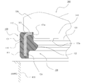
- FIG. 4 is a schematic cross-sectional view showing a state when the gasket according to the first embodiment of the present invention is attached.
- FIG. 5 is a schematic cross-sectional view showing a state when the jig according to the first embodiment of the present invention is inserted into the gasket in the wrong direction.
- the gasket 100 is mounted in the insertion hole 610 of the housing 600 from the small diameter inner peripheral surface portion 123 side. That is, in this embodiment, the gasket 100 is inserted into the insertion hole 610 by the jig 200 in the direction opposite to the insertion direction of the shaft 500 with respect to the insertion hole 610.
- the jig 200 includes a small-diameter outer peripheral surface portion 210, a medium-diameter outer peripheral surface portion 220, and a large-diameter outer peripheral surface portion 230 in order from the tip side.
- the small-diameter outer peripheral surface portion 210 is configured to be able to hold the gasket 100 by being press-fitted into the inner peripheral surface of the seal protrusion 122 of the gasket 100.
- the outer diameter of the medium-diameter outer peripheral surface portion 220 is larger than the inner diameter of the small-diameter inner peripheral surface portion 123 of the gasket 100, smaller than the inner diameter of the large-diameter inner peripheral surface portion 124, and smaller than the outer diameter of the small-diameter outer peripheral surface portion 210 of the jig 200. It is configured to be large. Further, the outer diameter of the large-diameter outer peripheral surface portion 230 is larger than the inner diameter of the large-diameter inner peripheral surface portion 124 of the gasket 100, and is larger than the outer diameter of the medium-diameter outer peripheral surface portion 220 of the jig 200.
- FIG. 4 shows a state in which the jig 200 is inserted into the gasket 100 from the large-diameter inner peripheral surface portion 124 side.
- the stepped surface 231 between the medium-diameter outer peripheral surface portion 220 and the large-diameter outer peripheral surface portion 230 abuts on the end surface of the gasket 100 on the large-diameter inner peripheral surface portion 124 side, and the small-diameter outer peripheral surface portion 210 is press-fitted into the inner peripheral surface of the seal protrusion 122. NS.
- the gasket 100 is held by the jig 200.
- the gasket 100 can be mounted in the insertion hole 610 by inserting the gasket 100 into the insertion hole 610 of the housing 600 while the gasket 100 is held by the jig 200.
- FIG. 5 shows a state in which the jig 200 is inserted into the gasket 100 from the small diameter inner peripheral surface portion 123 side.
- the stepped surface 221 between the small-diameter outer peripheral surface portion 210 and the medium-diameter outer peripheral surface portion 220 abuts on the end surface of the gasket 100 on the small-diameter inner peripheral surface portion 123 side, and does not reach the position where the small-diameter outer peripheral surface portion 210 contacts the seal protrusion 122. Therefore, the gasket 100 cannot be held on the jig 200.
- Example 2 shows Example 2 of the present invention.
- the case where the gasket is attached to the insertion hole from the small diameter inner peripheral surface side is shown.
- this embodiment the case of the structure in which the gasket is attached to the insertion hole from the large-diameter inner peripheral surface side is shown. Since other basic configurations and operations are the same as those in the first embodiment, the same components are designated by the same reference numerals, and the description thereof will be omitted as appropriate.
- the gasket 100 according to the present embodiment has the same basic configuration as the gasket 100 described in the first embodiment. However, in the case of this embodiment, it is desirable that a plurality of protrusions 123a shown by dotted lines are provided on the inner peripheral surface portion 123 of the seal main body portion 120 at intervals in the circumferential direction. However, it is different from the case of Example 1.
- FIG. 6 is a schematic cross-sectional view of a sealed structure including the gasket according to the second embodiment of the present invention.
- the shaft 500 is configured to be inserted from the sealing target side (O) to be sealed toward the opposite side (A). That is, in FIG. 6, the shaft 500 is inserted into the insertion hole 610 in the direction of arrow P. Before the shaft 500 is inserted into the insertion hole 610, the gasket 100 is attached to the insertion hole 610 in advance.
- the outer peripheral sealing portion 121 is fitted and fixed to the inner peripheral surface of the insertion hole 610, and the sealing protrusion 122 is brought into close contact with the outer peripheral surface 510 of the shaft 500, whereby the gasket 100 , The annular gap between the housing 600X and the shaft 500 is sealed.
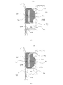
- FIG. 7 is a schematic cross-sectional view showing a state when the gasket according to the second embodiment of the present invention is attached.
- FIG. 8 is a schematic cross-sectional view showing a state in which the jig according to the second embodiment of the present invention is inserted into the gasket in the wrong direction.
- the gasket 100 is mounted in the insertion hole 610 of the housing 600X from the large diameter inner peripheral surface portion 124 side. That is, in this embodiment, the gasket 100 is inserted into the insertion hole 610 by the jig 300 in the same direction as the insertion direction of the shaft 500 with respect to the insertion hole 610.
- the jig 300 includes a small-diameter outer peripheral surface portion 310 and a large-diameter outer peripheral surface portion 320 in this order from the tip end side.
- the small-diameter outer peripheral surface portion 310 is configured to be able to hold the gasket 100 by being press-fitted into the inner peripheral surface of the small-diameter inner peripheral surface portion 123 of the gasket 100.
- the outer diameter of the large-diameter outer peripheral surface portion 320 is configured to be larger than the inner diameter of the large-diameter inner peripheral surface portion 124 and larger than the outer diameter of the small-diameter outer peripheral surface portion 310.
- FIG. 7 shows a state in which the jig 300 is inserted into the gasket 100 from the small diameter inner peripheral surface portion 123 side.
- the stepped surface 321 between the small-diameter outer peripheral surface portion 310 and the large-diameter outer peripheral surface portion 320 abuts on the end surface of the gasket 100 on the small-diameter inner peripheral surface portion 123 side, and the small-diameter outer peripheral surface portion 310 is press-fitted into the inner peripheral surface of the small-diameter inner peripheral surface portion 123.
- the gasket 100 is held by the jig 300.
- the gasket 100 can be mounted in the insertion hole 610 by inserting the gasket 100 into the insertion hole 610 of the housing 600X while the gasket 100 is held by the jig 300.
- FIG. 8 shows a state in which the jig 300 is inserted into the gasket 100 from the large-diameter inner peripheral surface portion 124 side.
- the stepped surface 321 between the small-diameter outer peripheral surface portion 310 and the large-diameter outer peripheral surface portion 320 abuts on the end surface of the gasket 100 on the large-diameter inner peripheral surface portion 124 side, and between the small-diameter outer peripheral surface portion 310 and the large-diameter inner peripheral surface portion 124.
- a gap S is formed. Therefore, the gasket 100 cannot be held on the jig 300.
- the small-diameter outer peripheral surface portion 310 of the jig 300 is press-fitted into the inner peripheral surface of the small-diameter inner peripheral surface portion 123 of the gasket 100 without increasing the force required for press-fitting, and the gasket 100 is pressed. Can be held.
- the reinforcing ring 110 is composed of the cylindrical portion 111 and the inward flange portion 112 provided at one end of the cylindrical portion 111 is shown.
- the reinforcing ring according to the present invention can also be applied when it is composed of a cylindrical portion and an outward flange portion provided at one end of the cylindrical portion. Further, the reinforcing ring according to the present invention can be applied even when it is composed of only a cylindrical portion.
Landscapes
- Engineering & Computer Science (AREA)
- General Engineering & Computer Science (AREA)
- Mechanical Engineering (AREA)
- Gasket Seals (AREA)
Abstract
ガスケットの装着方向の誤りを抑制することのできるガスケットの装着構造を提供する。 治具200がガスケット100対して大径内周面部124側から挿入されると、小径外周面部210がシール突起122の内周面に圧入されて、治具200にガスケット100が保持された状態となり、治具200がガスケット100に対して小径内周面部123側から挿入されると、小径外周面部210がシール突起122に接する位置まで届かないように構成されていることを特徴とする。
Description
本発明は、環状隙間を封止するためのガスケットの装着構造に関する。
従来、環状隙間を封止するためのガスケットが知られている。図9を参照して、従来例に係るガスケットについて説明する。図9は従来例に係るガスケットを備える密封構造の模式的断面図である。図示のガスケット700は、ハウジング600と、ハウジング600に設けられた挿通孔610に対して挿通される軸500との間の環状隙間を封止するために用いられる。また、軸500は、密封対象となる密封対象側(O)から、その反対側(A)に向けて挿通される。そして、軸500が挿通孔610に挿通される前に、不図示の治具によって、予め挿通孔610にガスケット700は装着される。
図9(a)に示すように、ガスケット700は、補強環710と、補強環710に一体的に設けられる弾性体製のシール本体部720とを備えている。また、補強環710は、円筒部711と、円筒部711における密封対象側(O)の端部に設けられる内向きフランジ部712とを有している。更に、シール本体部720は、挿通孔610の内周面に嵌合固定される外周シール部721と、軸500の外周面に密着するシール突起722とを一体に有している。
このように構成されるガスケット700は、補強環710における内向きフランジ部712が密封対象側(O)となるように、挿通孔610に装着される(図9(a)参照)。しかしながら、ガスケット700は、補強環710における内向きフランジ部712が密封対象側(O)とは反対側(A)となるようにも装着することができる(図9(b)参照)。このように、反対向きに装着されると、密封性は得られるものの、補強環710の内向きフランジ部712が大気等に曝されて錆びついてしまうなどのおそれもある。
ガスケット700の装着方向の誤りを防止する対策としては、ガスケット700の両端面のうちの一方にペイントすることで、装着後に、ペイントの有無をチェックすることも考えられる。しかしながら、この対策では、ペイント塗布と、そのチェックが必要になるため、コストアップとなってしまう。
本発明の目的は、ガスケットの装着方向の誤りを抑制することのできるガスケットの装着構造を提供することにある。
本発明は、上記課題を解決するために以下の手段を採用した。
本発明のガスケットの装着構造は、
ハウジングと、前記ハウジングに設けられた挿通孔に対して、密封対象となる密封対象側から、その反対側に向けて挿通される軸と、の間の環状隙間を封止するガスケットと、
前記軸が前記挿通孔に挿通される前に、予め前記挿通孔に前記ガスケットを装着するための治具と、により構成されるガスケットの装着構造であって、
前記ガスケットは、
補強環と、
前記挿通孔の内周面に嵌合固定される外周シール部と、前記軸の外周面に密着するシール突起とを一体に有し、前記補強環に一体的に設けられる弾性体製のシール本体部と、
を備え、
前記シール本体部の内周面のうち、前記シール突起よりも前記密封対象側は小径内周面部により構成され、前記シール突起よりも前記密封対象側とは反対側は前記小径内周面部よりも内径が大きな大径内周面部により構成されており、
前記治具は、
前記シール突起の内周面に圧入されることで前記ガスケットを保持可能に構成される小径外周面部と、
外径が、前記小径内周面部の内径よりも大きく、前記大径内周面部の内径よりも小さく、かつ前記小径外周面部の外径よりも大きな中径外周面部と、
外径が、前記大径内周面部の内径よりも大きく、かつ前記中径外周面部の外径よりも大きな大径外周面部と、
を備え、
前記治具が前記ガスケットに対して前記大径内周面部側から挿入されると、前記中径外周面部と前記大径外周面部との段差面が前記ガスケットにおける前記大径内周面部側の端面に突き当たり、前記小径外周面部が前記シール突起の内周面に圧入されて、前記治具に前記ガスケットが保持された状態となり、
前記治具が前記ガスケットに対して前記小径内周面部側から挿入されると、前記小径外周面部と前記中径外周面部との段差面が前記ガスケットにおける前記小径内周面部側の端面に突き当たり、前記小径外周面部が前記シール突起に接する位置まで届かないように構成されていることを特徴とする。
本発明によれば、治具がガスケットに対して大径内周面部側から挿入されると、ガスケットは治具に保持される。これに対して、治具がガスケットに対して小径内周面部側から挿入されると、ガスケットは治具には保持されない。従って、小径内周面部側からガスケットが挿通孔に装着される構造の場合においては、本発明の装着構造が採用されることで、ガスケットの装着方向の誤りを抑制することができる。
また、本発明の他のガスケットの装着構造は、
ハウジングと、前記ハウジングに設けられた挿通孔に対して、密封対象となる密封対象側から、その反対側に向けて挿通される軸と、の間の環状隙間を封止するガスケットと、
前記軸が前記挿通孔に挿通される前に、予め前記挿通孔に前記ガスケットを装着するための治具と、により構成されるガスケットの装着構造であって、
前記ガスケットは、
補強環と、
前記挿通孔の内周面に嵌合固定される外周シール部と、前記軸の外周面に密着するシール突起とを一体に有し、前記補強環に一体的に設けられる弾性体製のシール本体部と、
を備え、
前記シール本体部の内周面のうち、前記シール突起よりも前記密封対象側は小径内周面部により構成され、前記シール突起よりも前記密封対象側とは反対側は前記小径内周面部よりも内径が大きな大径内周面部により構成されており、
前記治具は、
前記小径内周面部の内周面に圧入されることで前記ガスケットを保持可能に構成される小径外周面部と、
外径が、前記大径内周面部の内径よりも大きく、かつ前記小径外周面部の外径よりも大きな大径外周面部と、
を備え、
前記治具が前記ガスケットに対して前記小径内周面部側から挿入されると、前記小径外周面部と前記大径外周面部との段差面が前記ガスケットにおける前記小径内周面部側の端面に突き当たり、前記小径外周面部が前記小径内周面部の内周面に圧入されて、前記治具に前記ガスケットが保持された状態となり、
前記治具が前記ガスケットに対して前記大径内周面部側から挿入されると、前記小径外周面部と前記大径外周面部との段差面が前記ガスケットにおける前記大径内周面部側の端面に突き当たり、前記小径外周面部と前記大径内周面部との間には隙間が形成されるように構成されていることを特徴とする。
本発明によれば、治具がガスケットに対して小径内周面部側から挿入されると、ガスケットは治具に保持される。これに対して、治具がガスケットに対して大径内周面部側から挿入されると、ガスケットは治具には保持されない。従って、大径内周面部側からガスケットが挿通孔に装着される構造の場合においては、本発明の装着構造が採用されることで、ガスケットの装着方向の誤りを抑制することができる。
前記小径内周面部には、前記小径外周面部に圧縮される突起が周方向に間隔を空けて複数設けられているとよい。
これにより、圧入に必要な力を高めることなく、治具の小径外周面部をガスケットの小径内周面部の内周面に圧入させて、ガスケットを保持することができる。
以上説明したように、本発明によれば、ガスケットの装着方向の誤りを抑制することができる。
以下に図面を参照して、この発明を実施するための形態を、実施例に基づいて例示的に詳しく説明する。ただし、この実施例に記載されている構成部品の寸法、材質、形状、その相対配置などは、特に特定的な記載がない限りは、この発明の範囲をそれらのみに限定する趣旨のものではない。
(実施例1)
図1~図5を参照して、本発明の実施例1に係るガスケットの装着構造について説明する。本実施例に係るガスケットは、例えば、自動車の電動オイルポンプ用シールとして好適に適用することができる。ただし、本実施例に係るガスケットは、自動車に備えられる各部の密封構造部の他、一般的な産業機械に備えられる密封構造部にも適用可能である。
図1~図5を参照して、本発明の実施例1に係るガスケットの装着構造について説明する。本実施例に係るガスケットは、例えば、自動車の電動オイルポンプ用シールとして好適に適用することができる。ただし、本実施例に係るガスケットは、自動車に備えられる各部の密封構造部の他、一般的な産業機械に備えられる密封構造部にも適用可能である。
<ガスケット>
特に、図1及び図2を参照して、本実施例に係るガスケットについて説明する。図1は本発明の実施例1に係るガスケットの平面図である。図2は本発明の実施例1に係るガスケットの一部破断断面図である。なお、図2中の断面図は、図1中のAA断面図である。また、図1,2中の点線で示した部分(突起123a)は、実施例2に係るガスケットの構成に関する部分である。
特に、図1及び図2を参照して、本実施例に係るガスケットについて説明する。図1は本発明の実施例1に係るガスケットの平面図である。図2は本発明の実施例1に係るガスケットの一部破断断面図である。なお、図2中の断面図は、図1中のAA断面図である。また、図1,2中の点線で示した部分(突起123a)は、実施例2に係るガスケットの構成に関する部分である。
本実施例に係るガスケット100は、金属などにより構成される補強環110と、補強環110に一体的に設けられる弾性体製(例えばゴム製)のシール本体部120とから構成される。例えば、補強環110をインサート部品として、インサート成形によりシール本体部120を成形することにより、ガスケット100を得ることができる。
補強環110は、円筒部111と、円筒部111における一端部(密封構造において、密封対象側の端部)に設けられる内向きフランジ部112とを備えている。
シール本体部120は、外周面側の外周シール部121と、内周面側のシール突起122とを一体に有している。また、シール本体部120の内周面のうち、シール突起122よりも一端側(密封構造において密封対象側)は小径内周面部123により構成され、シール突起122よりも他端側(密封対象側とは反対側)は小径内周面部123よりも内径が大きな大径内周面部124により構成されている。
<密封構造>
特に、図3を参照して、本実施例に係るガスケットを備える密封構造について説明する。図3は本発明の実施例1に係るガスケットを備える密封構造の模式的断面図である。本実施例に係る密封構造は、ハウジング600と、ハウジング600に設けられた挿通孔610に対して挿通される軸500と、これらハウジング600と軸500との間の環状隙間を封止するガスケット100とから構成される。本実施例においては、軸500は、密封対象となる密封対象側(O)から、その反対側(A)に向けて挿通されるように構成されている。すなわち、図3中、矢印P方向に軸500は挿通孔610に挿通される。なお、軸500が挿通孔610に挿通される前に、予め挿通孔610にガスケット100は装着される。また、密封対象側(O)には油などの密封対象流体が密封され、反対側(A)は、例えば、大気に曝される。
特に、図3を参照して、本実施例に係るガスケットを備える密封構造について説明する。図3は本発明の実施例1に係るガスケットを備える密封構造の模式的断面図である。本実施例に係る密封構造は、ハウジング600と、ハウジング600に設けられた挿通孔610に対して挿通される軸500と、これらハウジング600と軸500との間の環状隙間を封止するガスケット100とから構成される。本実施例においては、軸500は、密封対象となる密封対象側(O)から、その反対側(A)に向けて挿通されるように構成されている。すなわち、図3中、矢印P方向に軸500は挿通孔610に挿通される。なお、軸500が挿通孔610に挿通される前に、予め挿通孔610にガスケット100は装着される。また、密封対象側(O)には油などの密封対象流体が密封され、反対側(A)は、例えば、大気に曝される。
以上のように構成される密封構造によれば、挿通孔610の内周面に外周シール部121が嵌合固定され、シール突起122が軸500の外周面510に密着することで、ガスケット100によって、ハウジング600と軸500との間の環状隙間が封止される。
<ガスケットの装着構造>
特に、図4及び図5を参照して、本実施例に係るガスケットの装着構造について説明する。図4は本発明の実施例1に係るガスケットの装着時の様子を示す模式的断面図である。図5は本発明の実施例1に係る治具を誤った方向でガスケットに挿入した場合の様子を示す模式的断面図である。
特に、図4及び図5を参照して、本実施例に係るガスケットの装着構造について説明する。図4は本発明の実施例1に係るガスケットの装着時の様子を示す模式的断面図である。図5は本発明の実施例1に係る治具を誤った方向でガスケットに挿入した場合の様子を示す模式的断面図である。
本実施例においては、小径内周面部123側からガスケット100がハウジング600の挿通孔610に装着される構造となっている。すなわち、本実施例においては、挿通孔610に対する軸500の挿通方向とは逆向きに、治具200によって、ガスケット100が挿通孔610に挿通される。
治具200は、先端側から順に、小径外周面部210と、中径外周面部220と、大径外周面部230とを備えている。小径外周面部210は、ガスケット100におけるシール突起122の内周面に圧入されることで、ガスケット100を保持可能に構成されている。中径外周面部220の外径は、ガスケット100の小径内周面部123の内径よりも大きく、大径内周面部124の内径よりも小さく、かつ治具200の小径外周面部210の外径よりも大きくなるように構成されている。また、大径外周面部230の外径は、ガスケット100の大径内周面部124の内径よりも大きく、かつ治具200の中径外周面部220の外径よりも大きく構成されている。
図4においては、治具200がガスケット100に対して大径内周面部124側から挿入される場合の様子を示している。この場合、中径外周面部220と大径外周面部230との段差面231がガスケット100における大径内周面部124側の端面に突き当たり、小径外周面部210がシール突起122の内周面に圧入される。これにより、治具200にガスケット100が保持された状態となる。このように、治具200にガスケット100を保持させた状態で、ハウジング600の挿通孔610にガスケット100を挿入させることで、ガスケット100を挿通孔610に装着させることができる。
図5においては、治具200がガスケット100に対して小径内周面部123側から挿入される場合の様子を示している。この場合、小径外周面部210と中径外周面部220との段差面221がガスケット100における小径内周面部123側の端面に突き当たり、小径外周面部210がシール突起122に接する位置まで届かない。従って、治具200にガスケット100を保持することができない。
<本実施例に係るガスケットの装着構造の優れた点>
本実施例に係るガスケット100の装着構造によれば、治具200がガスケット100に対して大径内周面部124側から挿入されると、ガスケット100は治具200に保持される。これに対して、治具200がガスケット100に対して小径内周面部123側から挿入されると、ガスケット100は治具200には保持されない。従って、本実施例のように、小径内周面部123側からガスケット100が挿通孔610に装着される構造の場合においては、ガスケット100の装着方向の誤りを抑制することができる。そのため、ガスケット100の装着方向の誤りを防止するために、ガスケット100にペイントする必要もない。また、ガスケット100は正しい方向に、より確実に装着されるため、補強環110が錆びてしまうことも抑制することができる。
本実施例に係るガスケット100の装着構造によれば、治具200がガスケット100に対して大径内周面部124側から挿入されると、ガスケット100は治具200に保持される。これに対して、治具200がガスケット100に対して小径内周面部123側から挿入されると、ガスケット100は治具200には保持されない。従って、本実施例のように、小径内周面部123側からガスケット100が挿通孔610に装着される構造の場合においては、ガスケット100の装着方向の誤りを抑制することができる。そのため、ガスケット100の装着方向の誤りを防止するために、ガスケット100にペイントする必要もない。また、ガスケット100は正しい方向に、より確実に装着されるため、補強環110が錆びてしまうことも抑制することができる。
(実施例2)
図1,2及び図6~図8には、本発明の実施例2が示されている。上記実施例1では、小径内周面部側からガスケットが挿通孔に装着される構造の場合を示した。これに対し、本実施例においては、大径内周面部側からガスケットが挿通孔に装着される構造の場合を示す。その他の基本的な構成および作用については実施例1と同一なので、同一の構成部分については同一の符号を付して、その説明は適宜省略する。
図1,2及び図6~図8には、本発明の実施例2が示されている。上記実施例1では、小径内周面部側からガスケットが挿通孔に装着される構造の場合を示した。これに対し、本実施例においては、大径内周面部側からガスケットが挿通孔に装着される構造の場合を示す。その他の基本的な構成および作用については実施例1と同一なので、同一の構成部分については同一の符号を付して、その説明は適宜省略する。
<ガスケット>
特に、図1及び図2を参照して、本実施例に係るガスケットについて説明する。本実施例に係るガスケット100は、上記実施例1で説明したガスケット100と基本的な構成は同一である。ただし、本実施例の場合には、シール本体部120の内周面に設けられた小径内周面部123に、点線で示す突起123aが周方向に間隔を空けて複数設けられるのが望ましい点のみが、実施例1の場合とは異なっている。
特に、図1及び図2を参照して、本実施例に係るガスケットについて説明する。本実施例に係るガスケット100は、上記実施例1で説明したガスケット100と基本的な構成は同一である。ただし、本実施例の場合には、シール本体部120の内周面に設けられた小径内周面部123に、点線で示す突起123aが周方向に間隔を空けて複数設けられるのが望ましい点のみが、実施例1の場合とは異なっている。
<密封構造>
特に、図6を参照して、本実施例に係るガスケットを備える密封構造について説明する。図6は本発明の実施例2に係るガスケットを備える密封構造の模式的断面図である。本実施例に係る密封構造においても、ハウジング600Xと、ハウジング600Xに設けられた挿通孔610に対して挿通される軸500と、これらハウジング600Xと軸500との間の環状隙間を封止するガスケット100とから構成される。また、本実施例においても、軸500は、密封対象となる密封対象側(O)から、その反対側(A)に向けて挿通されるように構成されている。すなわち、図6中、矢印P方向に軸500は挿通孔610に挿通される。なお、軸500が挿通孔610に挿通される前に、予め挿通孔610にガスケット100は装着される。
特に、図6を参照して、本実施例に係るガスケットを備える密封構造について説明する。図6は本発明の実施例2に係るガスケットを備える密封構造の模式的断面図である。本実施例に係る密封構造においても、ハウジング600Xと、ハウジング600Xに設けられた挿通孔610に対して挿通される軸500と、これらハウジング600Xと軸500との間の環状隙間を封止するガスケット100とから構成される。また、本実施例においても、軸500は、密封対象となる密封対象側(O)から、その反対側(A)に向けて挿通されるように構成されている。すなわち、図6中、矢印P方向に軸500は挿通孔610に挿通される。なお、軸500が挿通孔610に挿通される前に、予め挿通孔610にガスケット100は装着される。
以上のように構成される密封構造によれば、挿通孔610の内周面に外周シール部121が嵌合固定され、シール突起122が軸500の外周面510に密着することで、ガスケット100によって、ハウジング600Xと軸500との間の環状隙間が封止される。
<ガスケットの装着構造>
特に、図7及び図8を参照して、本実施例に係るガスケットの装着構造について説明する。図7は本発明の実施例2に係るガスケットの装着時の様子を示す模式的断面図である。図8は本発明の実施例2に係る治具を誤った方向でガスケットに挿入した場合の様子を示す模式的断面図である。
特に、図7及び図8を参照して、本実施例に係るガスケットの装着構造について説明する。図7は本発明の実施例2に係るガスケットの装着時の様子を示す模式的断面図である。図8は本発明の実施例2に係る治具を誤った方向でガスケットに挿入した場合の様子を示す模式的断面図である。
本実施例においては、大径内周面部124側からガスケット100がハウジング600Xの挿通孔610に装着される構造となっている。すなわち、本実施例においては、挿通孔610に対する軸500の挿通方向と同じ向きに、治具300によって、ガスケット100が挿通孔610に挿通される。
治具300は、先端側から順に、小径外周面部310と、大径外周面部320とを備えている。小径外周面部310は、ガスケット100における小径内周面部123の内周面に圧入されることでガスケット100を保持可能に構成されている。大径外周面部320の外径は、大径内周面部124の内径よりも大きく、かつ小径外周面部310の外径よりも大きくなるように構成されている。
図7においては、治具300がガスケット100に対して小径内周面部123側から挿入される場合の様子を示している。この場合、小径外周面部310と大径外周面部320との段差面321がガスケット100における小径内周面部123側の端面に突き当たり、小径外周面部310が小径内周面部123の内周面に圧入される。これにより、治具300にガスケット100が保持された状態となる。このように、治具300にガスケット100を保持させた状態で、ハウジング600Xの挿通孔610にガスケット100を挿入させることで、ガスケット100を挿通孔610に装着させることができる。
図8においては、治具300がガスケット100に対して大径内周面部124側から挿入される場合の様子を示している。この場合、小径外周面部310と大径外周面部320との段差面321がガスケット100における大径内周面部124側の端面に突き当たり、小径外周面部310と大径内周面部124との間には隙間Sが形成される。従って、治具300にガスケット100を保持することができない。
<本実施例に係るガスケットの装着構造の優れた点>
本実施例に係るガスケット100の装着構造によれば、治具300がガスケット100に対して小径内周面部123側から挿入されると、ガスケット100は治具300に保持される。これに対して、治具300がガスケット100に対して大径内周面部124側から挿入されると、ガスケット100は治具300には保持されない。従って、本実施例のように、大径内周面部124側からガスケット100が挿通孔610に装着される構造の場合においては、ガスケット100の装着方向の誤りを抑制することができる。そのため、ガスケット100の装着方向の誤りを防止するために、ガスケット100にペイントする必要もない。また、ガスケット100は正しい方向に、より確実に装着されるため、補強環110が錆びてしまうことも抑制することができる。
本実施例に係るガスケット100の装着構造によれば、治具300がガスケット100に対して小径内周面部123側から挿入されると、ガスケット100は治具300に保持される。これに対して、治具300がガスケット100に対して大径内周面部124側から挿入されると、ガスケット100は治具300には保持されない。従って、本実施例のように、大径内周面部124側からガスケット100が挿通孔610に装着される構造の場合においては、ガスケット100の装着方向の誤りを抑制することができる。そのため、ガスケット100の装着方向の誤りを防止するために、ガスケット100にペイントする必要もない。また、ガスケット100は正しい方向に、より確実に装着されるため、補強環110が錆びてしまうことも抑制することができる。
また、本実施例においては、ガスケット100の小径内周面部123に、治具300における小径外周面部310に圧縮される突起123aが周方向に間隔を空けて複数設けられる構成を採用すると好適である。このような突起123aを複数設けることで、圧入に必要な力を高めることなく、治具300の小径外周面部310をガスケット100の小径内周面部123の内周面に圧入させて、ガスケット100を保持することができる。
上記各実施例においては、補強環110が、円筒部111と、円筒部111における一端部に設けられる内向きフランジ部112とにより構成される場合を示した。しかしながら、本発明に係る補強環は、円筒部と、円筒部の一端部設けられる外向きフランジ部とにより構成される場合も適用可能である。また、本発明に係る補強環は、円筒部のみから構成される場合も適用可能である。
100 ガスケット
110 補強環
111 円筒部
112 内向きフランジ部
120 シール本体部
121 外周シール部
122 シール突起
123 小径内周面部
123a 突起
124 大径内周面部
200 治具
210 小径外周面部
220 中径外周面部
221 段差面
230 大径外周面部
231 段差面
300 治具
310 小径外周面部
320 大径外周面部
321 段差面
500 軸
510 外周面
600,600X ハウジング
610 挿通孔
110 補強環
111 円筒部
112 内向きフランジ部
120 シール本体部
121 外周シール部
122 シール突起
123 小径内周面部
123a 突起
124 大径内周面部
200 治具
210 小径外周面部
220 中径外周面部
221 段差面
230 大径外周面部
231 段差面
300 治具
310 小径外周面部
320 大径外周面部
321 段差面
500 軸
510 外周面
600,600X ハウジング
610 挿通孔
Claims (3)
- ハウジングと、前記ハウジングに設けられた挿通孔に対して、密封対象となる密封対象側から、その反対側に向けて挿通される軸と、の間の環状隙間を封止するガスケットと、
前記軸が前記挿通孔に挿通される前に、予め前記挿通孔に前記ガスケットを装着するための治具と、により構成されるガスケットの装着構造であって、
前記ガスケットは、
補強環と、
前記挿通孔の内周面に嵌合固定される外周シール部と、前記軸の外周面に密着するシール突起とを一体に有し、前記補強環に一体的に設けられる弾性体製のシール本体部と、
を備え、
前記シール本体部の内周面のうち、前記シール突起よりも前記密封対象側は小径内周面部により構成され、前記シール突起よりも前記密封対象側とは反対側は前記小径内周面部よりも内径が大きな大径内周面部により構成されており、
前記治具は、
前記シール突起の内周面に圧入されることで前記ガスケットを保持可能に構成される小径外周面部と、
外径が、前記小径内周面部の内径よりも大きく、前記大径内周面部の内径よりも小さく、かつ前記小径外周面部の外径よりも大きな中径外周面部と、
外径が、前記大径内周面部の内径よりも大きく、かつ前記中径外周面部の外径よりも大きな大径外周面部と、
を備え、
前記治具が前記ガスケットに対して前記大径内周面部側から挿入されると、前記中径外周面部と前記大径外周面部との段差面が前記ガスケットにおける前記大径内周面部側の端面に突き当たり、前記小径外周面部が前記シール突起の内周面に圧入されて、前記治具に前記ガスケットが保持された状態となり、
前記治具が前記ガスケットに対して前記小径内周面部側から挿入されると、前記小径外周面部と前記中径外周面部との段差面が前記ガスケットにおける前記小径内周面部側の端面に突き当たり、前記小径外周面部が前記シール突起に接する位置まで届かないように構成されていることを特徴とするガスケットの装着構造。 - ハウジングと、前記ハウジングに設けられた挿通孔に対して、密封対象となる密封対象側から、その反対側に向けて挿通される軸と、の間の環状隙間を封止するガスケットと、 前記軸が前記挿通孔に挿通される前に、予め前記挿通孔に前記ガスケットを装着するための治具と、により構成されるガスケットの装着構造であって、
前記ガスケットは、
補強環と、
前記挿通孔の内周面に嵌合固定される外周シール部と、前記軸の外周面に密着するシール突起とを一体に有し、前記補強環に一体的に設けられる弾性体製のシール本体部と、
を備え、
前記シール本体部の内周面のうち、前記シール突起よりも前記密封対象側は小径内周面部により構成され、前記シール突起よりも前記密封対象側とは反対側は前記小径内周面部よりも内径が大きな大径内周面部により構成されており、
前記治具は、
前記小径内周面部の内周面に圧入されることで前記ガスケットを保持可能に構成される小径外周面部と、
外径が、前記大径内周面部の内径よりも大きく、かつ前記小径外周面部の外径よりも大きな大径外周面部と、
を備え、
前記治具が前記ガスケットに対して前記小径内周面部側から挿入されると、前記小径外周面部と前記大径外周面部との段差面が前記ガスケットにおける前記小径内周面部側の端面に突き当たり、前記小径外周面部が前記小径内周面部の内周面に圧入されて、前記治具に前記ガスケットが保持された状態となり、
前記治具が前記ガスケットに対して前記大径内周面部側から挿入されると、前記小径外周面部と前記大径外周面部との段差面が前記ガスケットにおける前記大径内周面部側の端面に突き当たり、前記小径外周面部と前記大径内周面部との間には隙間が形成されるように構成されていることを特徴とするガスケットの装着構造。 - 前記小径内周面部には、前記小径外周面部に圧縮される突起が周方向に間隔を空けて複数設けられていることを特徴とする請求項2に記載のガスケットの装着構造。
Priority Applications (3)
| Application Number | Priority Date | Filing Date | Title |
|---|---|---|---|
| JP2022516971A JP7170938B2 (ja) | 2020-04-23 | 2021-04-13 | ガスケットの装着構造 |
| CN202180014859.6A CN115087823A (zh) | 2020-04-23 | 2021-04-13 | 密封垫的安装结构 |
| US17/801,515 US20230003302A1 (en) | 2020-04-23 | 2021-04-13 | Gasket mounting structure |
Applications Claiming Priority (2)
| Application Number | Priority Date | Filing Date | Title |
|---|---|---|---|
| JP2020-076863 | 2020-04-23 | ||
| JP2020076863 | 2020-04-23 |
Publications (1)
| Publication Number | Publication Date |
|---|---|
| WO2021215295A1 true WO2021215295A1 (ja) | 2021-10-28 |
Family
ID=78269374
Family Applications (1)
| Application Number | Title | Priority Date | Filing Date |
|---|---|---|---|
| PCT/JP2021/015264 WO2021215295A1 (ja) | 2020-04-23 | 2021-04-13 | ガスケットの装着構造 |
Country Status (4)
| Country | Link |
|---|---|
| US (1) | US20230003302A1 (ja) |
| JP (1) | JP7170938B2 (ja) |
| CN (1) | CN115087823A (ja) |
| WO (1) | WO2021215295A1 (ja) |
Citations (5)
| Publication number | Priority date | Publication date | Assignee | Title |
|---|---|---|---|---|
| JPS6219178U (ja) * | 1985-07-17 | 1987-02-04 | ||
| JPH03130330U (ja) * | 1990-04-16 | 1991-12-27 | ||
| JPH0663234U (ja) * | 1993-02-10 | 1994-09-06 | 三菱自動車工業株式会社 | シール材の圧入装置 |
| JP2005205558A (ja) * | 2004-01-23 | 2005-08-04 | Fuji Heavy Ind Ltd | オイルシール圧入装置 |
| JP2006300114A (ja) * | 2005-04-18 | 2006-11-02 | Jtekt Corp | 環状シール部材の圧入状態判定方法とシール組込装置 |
Family Cites Families (26)
| Publication number | Priority date | Publication date | Assignee | Title |
|---|---|---|---|---|
| US2861330A (en) * | 1956-12-20 | 1958-11-25 | George H Kratz | Retainer applying tool |
| US2998644A (en) * | 1958-06-16 | 1961-09-05 | Federal Mogul Bower Bearings | Seal driver assembly |
| US3030702A (en) * | 1959-03-02 | 1962-04-24 | Chicago Rawhide Mfg Co | Seal installation tool |
| US3165949A (en) * | 1961-08-30 | 1965-01-19 | Federal Mogul Bower Bearings | Seal driver assembly |
| US4218813A (en) * | 1979-01-31 | 1980-08-26 | Garlock Inc. | Method and tool for installing shafts through seals |
| JPS59116179U (ja) * | 1983-01-24 | 1984-08-06 | エヌオーケー株式会社 | オイルシ−ル取付用治具 |
| US4551898A (en) * | 1984-02-06 | 1985-11-12 | Kent-Moore Corporation | Crankshaft seal installing tool |
| GB2199381A (en) * | 1986-12-23 | 1988-07-06 | Ford Motor Co | Seal installation |
| US4815884A (en) * | 1988-05-23 | 1989-03-28 | General Motors Corporation | Removable seal protector and shaft insertion guide |
| JP3130330B2 (ja) | 1991-06-12 | 2001-01-31 | 沖電気工業株式会社 | 半導体集積回路の製造方法 |
| US5875550A (en) * | 1997-07-23 | 1999-03-02 | Freudenberg-Nok General Partnership | Steer spindle bullet tool |
| US5893202A (en) * | 1997-09-19 | 1999-04-13 | Chiquita Brands, Inc. | Tool and method for installing the inner oil seal in the hub of a wheel assembly |
| DE10325254C5 (de) * | 2003-06-03 | 2011-03-31 | Carl Freudenberg Kg | Montageschutzring |
| US7096551B2 (en) * | 2004-05-13 | 2006-08-29 | Skf Usa Inc. | Installation tool for oil and grease seals |
| US7959157B2 (en) * | 2006-12-13 | 2011-06-14 | Skf Usa Inc. | Seal with guide member |
| US7900357B2 (en) * | 2007-03-20 | 2011-03-08 | GM Global Technology Operations LLC | Seal installation tool and method of using same |
| US8028852B2 (en) * | 2008-05-30 | 2011-10-04 | Freudenberg-Nok General Partnership | Two-piece shipping cap for a seal |
| US8756784B2 (en) * | 2010-01-22 | 2014-06-24 | Gm Global Technology Operations, Llc | Seal protector assembly |
| US8328200B2 (en) * | 2010-04-22 | 2012-12-11 | Freudenberg-Nok General Partnership | Multiple use installation aid for radial shaft seals |
| DE102014016722A1 (de) * | 2014-11-13 | 2016-05-19 | Carl Freudenberg Kg | Montagevorrichtung für einen Dichtring |
| WO2017135337A1 (ja) * | 2016-02-03 | 2017-08-10 | Nok株式会社 | ガスケット |
| US20210164570A1 (en) * | 2018-08-02 | 2021-06-03 | Nok Corporation | Sealing apparatus and gasket |
| CN113874640B (zh) * | 2019-07-24 | 2022-09-20 | Nok株式会社 | 密封装置 |
| WO2021079585A1 (ja) * | 2019-10-21 | 2021-04-29 | Nok株式会社 | ガスケット |
| JP7385624B2 (ja) * | 2021-06-09 | 2023-11-22 | 三菱電線工業株式会社 | 軸シール梱包用スリーブ |
| US11802622B2 (en) * | 2021-10-29 | 2023-10-31 | Kaco Gmbh + Co. Kg | Shaft seal, in particular radial shaft seal |
-
2021
- 2021-04-13 CN CN202180014859.6A patent/CN115087823A/zh active Pending
- 2021-04-13 WO PCT/JP2021/015264 patent/WO2021215295A1/ja active Application Filing
- 2021-04-13 JP JP2022516971A patent/JP7170938B2/ja active Active
- 2021-04-13 US US17/801,515 patent/US20230003302A1/en active Pending
Patent Citations (5)
| Publication number | Priority date | Publication date | Assignee | Title |
|---|---|---|---|---|
| JPS6219178U (ja) * | 1985-07-17 | 1987-02-04 | ||
| JPH03130330U (ja) * | 1990-04-16 | 1991-12-27 | ||
| JPH0663234U (ja) * | 1993-02-10 | 1994-09-06 | 三菱自動車工業株式会社 | シール材の圧入装置 |
| JP2005205558A (ja) * | 2004-01-23 | 2005-08-04 | Fuji Heavy Ind Ltd | オイルシール圧入装置 |
| JP2006300114A (ja) * | 2005-04-18 | 2006-11-02 | Jtekt Corp | 環状シール部材の圧入状態判定方法とシール組込装置 |
Also Published As
| Publication number | Publication date |
|---|---|
| JP7170938B2 (ja) | 2022-11-14 |
| JPWO2021215295A1 (ja) | 2021-10-28 |
| CN115087823A (zh) | 2022-09-20 |
| US20230003302A1 (en) | 2023-01-05 |
Similar Documents
| Publication | Publication Date | Title |
|---|---|---|
| JP3137481U (ja) | リップタイプシールの装着構造 | |
| JP6113733B2 (ja) | 密封装置 | |
| JP2008309263A (ja) | 密封装置 | |
| WO2019171771A1 (ja) | 密封装置及びその組立て方法 | |
| JP6456966B2 (ja) | メカニカルシール | |
| JPWO2009017022A1 (ja) | シール装置 | |
| US11187326B2 (en) | Mechanical seal | |
| WO2021215295A1 (ja) | ガスケットの装着構造 | |
| JP2001520738A (ja) | 金属製支持体を備えたラジアルシール | |
| JP5016423B2 (ja) | リップタイプシール | |
| JP4849235B2 (ja) | 密封装置 | |
| US20200278028A1 (en) | Sealing apparatus | |
| JP4727328B2 (ja) | 管部材の接合装置 | |
| US9297457B2 (en) | Sealing device | |
| JP2021032377A (ja) | 密封装置 | |
| JP2008025788A (ja) | 密封装置 | |
| WO2021014842A1 (ja) | 密封構造 | |
| JP2001074145A (ja) | 回転軸シール | |
| JP2008025392A (ja) | クランクシャフト用オイルシールの取り付け構造 | |
| JP7432367B2 (ja) | 密封装置 | |
| JPH1182751A (ja) | 密封装置 | |
| JP2002310305A (ja) | 密封装置 | |
| JP2021183858A (ja) | 密封装置 | |
| JP2005273693A (ja) | 密封装置 | |
| JP2003097716A (ja) | 車軸用密封装置 |
Legal Events
| Date | Code | Title | Description |
|---|---|---|---|
| 121 | Ep: the epo has been informed by wipo that ep was designated in this application |
Ref document number: 21792461 Country of ref document: EP Kind code of ref document: A1 |
|
| ENP | Entry into the national phase |
Ref document number: 2022516971 Country of ref document: JP Kind code of ref document: A |
|
| NENP | Non-entry into the national phase |
Ref country code: DE |
|
| 122 | Ep: pct application non-entry in european phase |
Ref document number: 21792461 Country of ref document: EP Kind code of ref document: A1 |