WO2016027430A1 - 燃料電池装置 - Google Patents
燃料電池装置 Download PDFInfo
- Publication number
- WO2016027430A1 WO2016027430A1 PCT/JP2015/003958 JP2015003958W WO2016027430A1 WO 2016027430 A1 WO2016027430 A1 WO 2016027430A1 JP 2015003958 W JP2015003958 W JP 2015003958W WO 2016027430 A1 WO2016027430 A1 WO 2016027430A1
- Authority
- WO
- WIPO (PCT)
- Prior art keywords
- flow path
- air
- path portion
- heat
- gas
- Prior art date
- Legal status (The legal status is an assumption and is not a legal conclusion. Google has not performed a legal analysis and makes no representation as to the accuracy of the status listed.)
- Ceased
Links
Images


Classifications
-
- H—ELECTRICITY
- H01—ELECTRIC ELEMENTS
- H01M—PROCESSES OR MEANS, e.g. BATTERIES, FOR THE DIRECT CONVERSION OF CHEMICAL ENERGY INTO ELECTRICAL ENERGY
- H01M8/00—Fuel cells; Manufacture thereof
- H01M8/04—Auxiliary arrangements, e.g. for control of pressure or for circulation of fluids
- H01M8/04007—Auxiliary arrangements, e.g. for control of pressure or for circulation of fluids related to heat exchange
- H01M8/04014—Heat exchange using gaseous fluids; Heat exchange by combustion of reactants
-
- H—ELECTRICITY
- H01—ELECTRIC ELEMENTS
- H01M—PROCESSES OR MEANS, e.g. BATTERIES, FOR THE DIRECT CONVERSION OF CHEMICAL ENERGY INTO ELECTRICAL ENERGY
- H01M8/00—Fuel cells; Manufacture thereof
- H01M8/06—Combination of fuel cells with means for production of reactants or for treatment of residues
- H01M8/0606—Combination of fuel cells with means for production of reactants or for treatment of residues with means for production of gaseous reactants
- H01M8/0612—Combination of fuel cells with means for production of reactants or for treatment of residues with means for production of gaseous reactants from carbon-containing material
- H01M8/0618—Reforming processes, e.g. autothermal, partial oxidation or steam reforming
-
- H—ELECTRICITY
- H01—ELECTRIC ELEMENTS
- H01M—PROCESSES OR MEANS, e.g. BATTERIES, FOR THE DIRECT CONVERSION OF CHEMICAL ENERGY INTO ELECTRICAL ENERGY
- H01M8/00—Fuel cells; Manufacture thereof
- H01M8/24—Grouping of fuel cells, e.g. stacking of fuel cells
- H01M8/2465—Details of groupings of fuel cells
- H01M8/2484—Details of groupings of fuel cells characterised by external manifolds
-
- H—ELECTRICITY
- H01—ELECTRIC ELEMENTS
- H01M—PROCESSES OR MEANS, e.g. BATTERIES, FOR THE DIRECT CONVERSION OF CHEMICAL ENERGY INTO ELECTRICAL ENERGY
- H01M8/00—Fuel cells; Manufacture thereof
- H01M8/10—Fuel cells with solid electrolytes
- H01M8/12—Fuel cells with solid electrolytes operating at high temperature, e.g. with stabilised ZrO2 electrolyte
- H01M2008/1293—Fuel cells with solid oxide electrolytes
-
- Y—GENERAL TAGGING OF NEW TECHNOLOGICAL DEVELOPMENTS; GENERAL TAGGING OF CROSS-SECTIONAL TECHNOLOGIES SPANNING OVER SEVERAL SECTIONS OF THE IPC; TECHNICAL SUBJECTS COVERED BY FORMER USPC CROSS-REFERENCE ART COLLECTIONS [XRACs] AND DIGESTS
- Y02—TECHNOLOGIES OR APPLICATIONS FOR MITIGATION OR ADAPTATION AGAINST CLIMATE CHANGE
- Y02E—REDUCTION OF GREENHOUSE GAS [GHG] EMISSIONS, RELATED TO ENERGY GENERATION, TRANSMISSION OR DISTRIBUTION
- Y02E60/00—Enabling technologies; Technologies with a potential or indirect contribution to GHG emissions mitigation
- Y02E60/30—Hydrogen technology
- Y02E60/50—Fuel cells
Definitions
- the present disclosure relates to a fuel cell device that generates power using fuel gas and oxidant gas.
- a fuel cell device is a power generator that directly converts chemical energy of fuel gas and oxidant gas into electrical energy. Its power generation efficiency is very high, and the discharged gas is relatively clean, so it is attracting attention as a next-generation power generation device.
- a cooling gas is introduced during a high load operation to lower the temperature of the cell stack.
- This disclosure is intended to provide a fuel cell device that can suppress a temperature distribution difference in the stacking direction in a fuel cell device having a cell stack in which flat single cells are stacked.
- a fuel cell device is a fuel cell device that generates electric power using a fuel gas and an oxidant gas, and reforms a raw material gas to generate a fuel gas, and heats through the oxidant gas.
- a cell stack that generates power by receiving supply of fuel gas and oxidant gas heated by the heating channel, and exhaust for passing combustion exhaust gas that burns the fuel gas discharged from the cell stack And a flow path.
- the oxidant gas flowing in from the inlet provided at one end of the heating flow path receives heat from the cell stack and the discharge flow path and flows out from the outlet provided at the other end of the heating flow path.
- This fuel cell device is provided with a heat return portion that returns the heat of the oxidant gas on the other end side to the oxidant gas on the one end side.
- the heat of the oxidant gas on the other end side of the heating flow path can be returned to the oxidant gas on the one end side of the heating flow path. Since the oxidant gas flowing into the heating flow path from the inlet increases in temperature as it flows in the heating flow path, the oxidant gas in the heating flow path when the heat is refluxed as described above. The temperature is adjusted in a uniform direction. In order to equalize the amount of radiant heat from the cell stack in the stacking direction, it is desirable to reduce the temperature difference between the cell stack temperature and the heating channel wall temperature in each part of the stacking direction. In the present disclosure, the temperature difference between the cell stack temperature and the heating channel wall temperature can be reduced because the oxidant gas temperature in the heating channel is adjusted in a uniform direction.
- the heat return unit is configured by folding at least the heating flow path so that one end side and the other end side are arranged close to each other.
- the heating channel has a first channel part that extends from below to above, and a second channel part that is connected to the first channel part and that goes from above to below.
- the discharge flow path can also have a third flow path portion that extends from the bottom to the top and a fourth flow path portion that is connected to the third flow path portion and that extends from the top to the bottom.
- the second flow path portion is arranged so as to surround the cell stack so as to receive radiant heat from the cell stack.
- the third flow path part, the fourth flow path part, and the first flow path part are arranged in order outside the second flow path part, so that the first flow path part receives heat from the fourth flow path part,
- the second flow path portion is configured to receive heat from the third flow path portion.
- the second flow path part, the third flow path part, the fourth flow path part, and the first flow path part are sequentially arranged so as to surround the cell stack, and the temperature of the oxidant gas flowing through the inside thereof.
- the first flow path portion configured to sufficiently rise is disposed on the outermost side. Therefore, the first flow path portion can serve as a heat insulating material, the amount of heat insulating material provided separately can be reduced, and a temperature distribution difference in the stacking direction can also be suppressed.
- a fuel cell device having a cell stack in which flat single cells are stacked, a fuel cell device capable of suppressing a temperature distribution difference in the stacking direction regardless of a flow path in the cell stack is provided. it can.
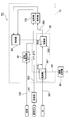
- FIG. 1 is a schematic diagram illustrating an internal structure of the fuel cell device according to the first embodiment of the present disclosure.
- FIG. 2 is a block diagram for explaining the flow of gas and water in the fuel cell apparatus shown in FIG.
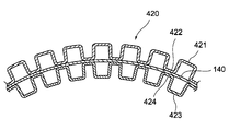
- FIG. 3 is a partial cross-sectional view for explaining the heat transfer area enlarged portion shown in FIG. 1.
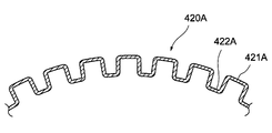
- FIG. 4 is a partial cross-sectional view for explaining a modification of the heat transfer area expanding portion shown in FIG.
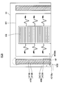
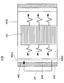
- FIG. 5 is a diagram for describing the configuration of the heat return unit in the fuel cell device according to the first embodiment of the present disclosure.
- FIG. 6 is a schematic diagram illustrating an internal structure of the fuel cell device according to the second embodiment of the present disclosure.
- FIG. 7 is a diagram for describing the configuration of the heat return unit in the fuel cell device according to the second embodiment of the present disclosure.
- FIG. 8 is a diagram for describing the configuration of the heat return unit in the fuel cell device according to the third embodiment of the present disclosure.
- FIG. 9 is a diagram for describing the configuration of the heat return unit in the fuel cell device according to the fourth embodiment of the present disclosure.
- FIG. 10 is a diagram for describing a specific example of the heat return unit in the fuel cell device according to the fourth embodiment of the present disclosure.
- FIG. 11 is a diagram for describing a specific example of the heat return unit in the fuel cell device according to the fourth embodiment of the present disclosure.
- the fuel cell apparatus FC includes a cell stack CS, a casing 10, a combustor 20, and a reforming unit 30.
- the cell stack CS is an aggregate of a plurality of single cells.
- Each single cell is a solid oxide fuel cell (SOFC), in which a fuel electrode (anode) is formed on one surface of a flat solid electrolyte, and air is formed on the other surface.
- the electrode (cathode) is formed.
- SOFC solid oxide fuel cell
- These fuel electrode and air electrode are both porous bodies formed of conductive ceramics.
- the cell stack CS In the cell stack CS, all single cells are stacked in the vertical direction, and these are electrically connected in series.
- the cell stack CS is erected on the upper surface side of the base plate BP via the stack adapter AD.
- the stack adapter AD is a plate-like member in which a plurality of gas flow paths are formed.
- the fuel gas is supplied to the cell stack CS through the stack adapter AD. Further, gas is discharged from the cell stack CS (discharge of residual fuel gas and air that has not been used for power generation) via the stack adapter AD.
- the base plate BP is a circular metal plate disposed horizontally within the casing 10. The internal space of the casing 10 is roughly divided into two upper and lower chambers by the base plate BP.
- the casing 10 is a substantially cylindrical housing that accommodates the cell stack CS, the combustor 20, the reforming unit 30, and the like.
- the casing 10 is entirely covered with a heat insulating material on its side surface and upper surface.
- the casing 10 includes a first cylindrical body 110, a second cylindrical body 120, a third cylindrical body 130, a fourth cylindrical body 140, a fifth cylindrical body 150, and a sixth cylindrical body 160. And have.
- the first cylindrical body 110, the second cylindrical body 120, the third cylindrical body 130, the fourth cylindrical body 140, the fifth cylindrical body 150, and the sixth cylindrical body 160 are all made of metal and centered. It is formed in a substantially cylindrical shape around the axis, and is arranged so that the respective central axes are coaxial.
- FIG. 1 is a schematic cross-sectional view of a fuel cell device FC whose cross section is a plane along the central axis.
- the first cylindrical body 110 is a cylindrical body arranged on the innermost side of the casing 10 and accommodates the cell stack CS and the stack adapter AD therein.
- the upper end of the first cylindrical body 110 is closed by a horizontal top plate 181. Further, the lower end of the first cylindrical body 110 is fixed in contact with the upper surface of the base plate BP.
- the height from the lower end to the upper end of the first cylindrical body 110 is higher than the height from the lower end of the stack adapter AD to the upper end of the cell stack CS. For this reason, the top plate 181 and the upper end of the cell stack CS are separated from each other.
- a plurality of air outlets 111 that are through holes are formed in the lower portion of the first cylindrical body 110.
- the plurality of air outlets 111 are formed at equal intervals at the same height.
- the air outlet 111 is a hole through which air for power generation (oxidant gas) supplied toward the cell stack CS passes.
- the second tubular body 120 is a tubular body disposed so as to surround the first tubular body 110 from the outside.
- a constant gap is formed between the inner surface of the second cylindrical body 120 and the outer surface of the first cylindrical body 110 over the entire circumference.
- a space formed between the second cylindrical body 120 and the first cylindrical body 110 is an air flow path 403 (corresponding to a second flow path portion) through which the power generation air is heated. .
- the inner diameter of the second cylindrical body 120 is substantially equal to the outer diameter of the base plate BP.
- the inner side surface in the vicinity of the lower end portion of the second cylindrical body 120 is in contact with the side surface of the base plate BP over the entire circumference. In the contact portion, the second cylindrical body 120 is fixed to the base plate BP. With such a configuration, gas cannot enter or leave between the space below the base plate BP and the air flow path 403.
- 3rd cylindrical body 130 is a cylindrical body arrange
- a constant gap is formed between the inner surface of the third cylindrical body 130 and the outer surface of the second cylindrical body 120 over the entire circumference.
- a space formed between the third cylindrical body 130 and the second cylindrical body 120 corresponds to an exhaust gas passage 411 (corresponding to a third passage portion) through which high-temperature combustion exhaust gas generated by combustion in the combustor 20 passes. ).
- the upper end of the third cylindrical body 130 is disposed at a position lower than the upper end of the second cylindrical body 120.
- the third cylindrical body 130 extends further below the lower end of the base plate BP.
- the fourth tubular body 140 is a tubular body disposed so as to surround the third tubular body 130 from the outside.
- a constant gap is formed over the entire circumference between the inner surface of the fourth cylindrical body 140 and the outer surface of the third cylindrical body 130.
- a space formed between the fourth cylindrical body 140 and the third cylindrical body 130 corresponds to an exhaust gas flow path 412 (a fourth flow path portion) through which high-temperature combustion exhaust gas generated by combustion in the combustor 20 passes. ).
- the exhaust gas flow channel 412 is connected to the exhaust gas flow channel 413 located further below.
- the exhaust gas channel 413 is a channel that guides the combustion exhaust gas to the side of the reforming unit 30.
- the upper end of the second cylindrical body 120 and the upper end of the fourth cylindrical body 140 have the same position in the height direction.
- the two are connected by a top plate 182 which is a horizontally arranged donut-shaped disk (a state in which a substantially circular hole is formed at a substantially central position, hereinafter the same). That is, the upper end of the second cylindrical body 120 is connected to the inner peripheral end of the top plate 182, and the upper end of the fourth cylindrical body 140 is connected to the outer peripheral end of the top plate 182.
- a gap is formed between the upper end of the third cylindrical body 130 and the top plate 182. For this reason, the exhaust gas flow channel 411 and the exhaust gas flow channel 412 are connected to each other at their upper ends.
- the lower end of the third cylindrical body 130 and the inner surface of the fourth cylindrical body 140 are connected by a bottom plate 183 that is a horizontally arranged donut-shaped disk. That is, the lower end of the exhaust gas passage 412 is closed by the bottom plate 183.
- a gas discharge pipe 191 is connected to the lower part of the fourth cylindrical body 140 (slightly above the bottom plate 183).
- the internal space of the gas exhaust pipe 191 communicates with the exhaust gas passage 413.
- the gas discharge pipe 191 is a pipe for discharging the combustion exhaust gas that has passed through the exhaust gas flow path 413 to the outside of the casing 10 and supplying it to the exhaust heat recovery unit 62 described later.
- the fourth tubular body 140 extends further downward than the lower end of the third tubular body 130.
- a horizontal flange portion 141 extending outward from the lower end is formed at the lower end of the fourth cylindrical body 140.
- the flange portion 141 is a flange used for fixing the casing 10 when the fuel cell device FC is installed.
- a bottom plate 184 that is a horizontal disc is disposed.
- the outer diameter of the bottom plate 184 is substantially equal to the inner diameter of the fourth cylindrical body 140.
- the bottom plate 184 is fixed in a state where the entire outer surface thereof is in contact with the inner surface of the fourth cylindrical body 140.
- a heat insulating material TI is disposed in the space below the bottom plate 184.
- the fifth cylindrical body 150 is a cylindrical body arranged on the outermost side of the casing 10, and is arranged so as to surround the upper part of the fourth cylindrical body 140 from the outside.
- a constant gap is formed between the inner side surface of the fifth cylindrical body 150 and the outer side surface of the fourth cylindrical body 140 over the entire circumference.
- a space formed between the fifth cylindrical body 150 and the fourth cylindrical body 140 is an air flow path 401 (corresponding to the first flow path portion) through which the power generation air is heated. .
- the fifth cylindrical body 150 extends further upward than the upper ends of any of the first cylindrical body 110, the second cylindrical body 120, the third cylindrical body 130, and the fourth cylindrical body 140.
- the upper end of the fifth cylindrical body 150 is closed by a horizontal top plate 185.
- a gap 402 is formed between the top plate 185 and the top plate 182.
- the upper end portion of the air flow path 401 and the upper end portion of the air flow path 403 are connected to each other through a gap 402.
- the lower end of the fifth cylindrical body 150 and the outer surface of the fourth cylindrical body 140 are connected to each other by a bottom plate 186 that is a horizontally arranged donut-shaped disk. That is, the lower end of the air flow path 401 is blocked by the bottom plate 186.
- An air introduction pipe 192 is connected to the lower part of the fifth cylindrical body 150 (slightly above the bottom plate 186). The internal space of the air introduction pipe 192 communicates with the air flow path 401.
- the air introduction pipe 192 is a pipe for introducing power generation air into the casing 10.
- the air temperature rise amount while passing through the air flow path 401 corresponding to the first flow path portion of the present disclosure is between the air flow path 403 corresponding to the second flow path portion of the present disclosure. It is comprised so that it may become larger than the temperature rise amount of air.
- the heat transfer area expanding portion 420 is provided between the air flow path 401 and the exhaust gas flow path 412 corresponding to the fourth flow path portion.
- the heat transfer area expanding section 420 will be described with reference to FIG.
- the heat transfer area expanding portion 420 is configured as a corrugated fin provided on both side surfaces of the fourth tubular body 140.
- Corrugated fins having convex portions 421 and concave portions 422 alternately are formed on the outer side of the fourth cylindrical body 140, that is, on the air flow path 401 side.
- Corrugated fins having convex portions 423 and concave portions 424 alternately are formed on the inner side of the fourth cylindrical body 140, that is, on the exhaust gas flow channel 412 side.
- the heat transfer area between the air flow path 401 and the exhaust gas flow path 412 is expanded, the heat of the combustion exhaust gas flowing through the exhaust gas flow path 412 is efficiently transmitted to the fourth cylindrical body 140, The transferred heat is also efficiently transferred to the air flowing through the air flow path 401. Therefore, the temperature rise amount of the air flowing through the air flow path 401 is larger than the temperature rise amount of the air flowing through the air flow path 403.
- the temperature of the upper part tends to be lower than the temperature of the middle part and the lower part. Therefore, the efficiently heated air passes from the air flow path 401 through the gap 402 to the air flow path 403 from above. Therefore, heat can be efficiently applied to the upper part of the cell stack CS.
- the temperature distribution in the stacking direction of the cell stack CS (the direction in which the air flow path 403 extends) can be reduced.
- a gap is provided between the top plate 181 and the top plate 185, and the air heated by flowing through the air flow path 401 enters the gap, so that the upper portion of the cell stack CS is Heat can be applied more efficiently.
- the convex part 421A and the recessed part 422A are directly provided in the 4th cylindrical body 140, and the effect similar to the heat-transfer area expansion part 420 mentioned above is also obtained as the heat-transfer-area expansion part 420A. be able to. Furthermore, since the heat transfer area expanding section 420A can reduce the number of parts compared to the heat transfer area expanding section 420 shown in FIG. 3, it is also possible to realize weight reduction and cost reduction.
- the sixth cylindrical body 160 is a cylindrical body that is disposed at a position inside the third cylindrical body 130 and on the lower side of the base plate BP.
- the sixth cylindrical body 160 has an upper cylindrical portion 161 that is an upper portion and a lower cylindrical portion 162 that is a lower portion.
- the diameter of the upper cylindrical portion 161 is smaller than the diameter of the lower cylindrical portion 162.
- the lower end of the upper cylindrical portion 161 and the upper end of the lower cylindrical portion 162 are connected by an intermediate portion 163 that is a horizontally arranged donut-shaped disk.
- the upper end of the upper cylindrical portion 161 is in contact with the lower surface of the base plate BP.
- the lower end of the lower cylindrical portion 162 is in contact with the upper surface of the bottom plate 184.
- the diameter of the lower cylindrical portion 162 is smaller than the diameter of the third cylindrical body 130. Therefore, a gap is formed between the third cylindrical body 130 and the sixth cylindrical body 160 over the entire circumference. Further, the reforming unit 30 is disposed in the gap, but a gap is also formed between the reforming unit 30 and the sixth cylindrical body 160 over the entire circumference.
- the space formed inside the sixth cylindrical body 160 is also referred to as “inner space 601”.
- a space formed between the lower cylindrical portion 162 of the sixth cylindrical body 160 and the inner cylinder 320 of the reforming unit 30 is also referred to as “outer space 602”.
- a plurality of outlets 165 that are through holes are formed at a position lower than the lower end portion of the reforming unit 30.
- the plurality of outlets 165 are formed so as to be arranged at equal intervals at the same height.
- the inner space 601 and the outer space 602 are communicated with each other through these outlets 165.
- the outlet 165 is a hole through which high-temperature flue gas generated by combustion in the combustor 20 passes.
- the combustor 20 mixes and burns residual fuel gas that has not been used for power generation (hereinafter also referred to as “residual fuel”) and residual air that has not been used for power generation (hereinafter also referred to as “residual air”).
- the combustor 20 is made of stainless steel.
- the entire combustor 20 is formed in a substantially cylindrical shape, and is disposed so as to protrude downward from the center of the lower surface of the base plate BP. Further, the combustor 20 is arranged at a position (a position along the central axis of the upper cylindrical portion 161) that is the center of the casing 10 in a top view.
- Residual fuel and residual air discharged from the cell stack CS are both supplied to the upper end of the combustor 20 through a flow path formed in the stack adapter AD and a flow path formed in the base plate BP. Thereafter, the residual fuel and the residual air reach the lower end portion of the combustor 20 through a flow path formed in the combustor 20, and are jetted downward while being mixed at the lower end portion. At the lower end of the combustor 20, the ejected residual fuel and residual air are combusted, and high-temperature combustion exhaust gas is generated. Further, the combustor 20 itself also becomes high temperature due to the heat of the combustion.
- An igniter IG is disposed below the combustor 20.
- the igniter IG is an apparatus for igniting a mixed gas of residual fuel and residual air ejected from the combustor 20 and starting combustion.
- the igniter IG penetrates the bottom plate 184 and the heat insulating material TI up and down, and is arranged in a state where an upper end portion where spark discharge is generated is brought close to the lower end of the combustor 20. Ignition by the igniter IG is performed when the fuel cell device FC is started.
- the configuration of the reforming unit 30 will be described.
- a reformer 302 that generates fuel gas (hydrogen-containing gas) from city gas by a reforming reaction and an evaporator 301 that generates water vapor and supplies the steam to the reformer 302 are integrated.
- the entire reforming unit 30 has a substantially cylindrical shape, and is disposed in a space between the third cylindrical body 130 and the sixth cylindrical body 160 in the casing 10.
- the reforming unit 30 includes an outer cylinder 310, an inner cylinder 320, a top plate 330, a first bottom plate 340, a second bottom plate 350, a first partition plate 360, and a second partition plate 370. Yes.
- the portion below the first bottom plate 340 is the portion of the reforming unit 30.
- the outline is defined.
- the outer cylinder 310 is a cylindrical body that forms the outer surface of the reforming unit 30.
- the central axis of the outer cylinder 310 coincides with the central axis of the third cylindrical body 130.
- the outer diameter of the outer cylinder 310 is substantially equal to the inner diameter of the third cylindrical body 130.
- the outer cylinder 310 is substantially in contact with the inner surface of the third cylindrical body 130 on the entire outer surface.
- the outer cylinder 310 extends further downward than the bottom plate 183.
- the inner cylinder 320 is a cylindrical body that forms the inner surface of the reforming unit 30.
- the central axis of the inner cylinder 320 coincides with the central axis of the third cylindrical body 130.
- the outer diameter of the inner cylinder 320 is smaller than the inner diameter of the outer cylinder 310. For this reason, a space is formed between the outer cylinder 310 and the inner cylinder 320. A part of the space is a space in which water flows as water vapor. Further, another part of the space is a space in which a reforming reaction occurs and fuel gas is generated.
- the inner diameter of the inner cylinder 320 is larger than the outer diameter of the lower cylindrical portion 162 of the third cylindrical body 130. For this reason, as already described, a gap is formed between the reforming unit 30 and the sixth cylindrical body 160 over the entire circumference.
- the height of the upper end of the inner cylinder 320 is the same as the height of the upper end of the outer cylinder 310.
- the lower end of the inner cylinder 320 is higher than the lower end of the outer cylinder 310 and is the same as the lower end of the bottom plate 183.
- the top plate 330 is a donut-shaped disk arranged horizontally.
- the outer surface of the top plate 330 is connected to the upper end portion of the inner surface of the outer cylinder 310. Further, the inner surface of the top plate 330 is connected to the upper end portion of the outer surface of the inner cylinder 320. Thus, the top plate 330 connects the upper end of the outer cylinder 310 and the upper end of the inner cylinder 320.
- the first bottom plate 340 is a donut-shaped disk arranged horizontally.
- the first bottom plate 340 is disposed at the same height as the bottom plate 183.
- the outer surface of the first bottom plate 340 is connected to the inner surface of the first partition plate 360 described later. Further, the inner side surface of the first bottom plate 340 is connected to the lower end portion of the inner side surface of the inner cylinder 320.
- the second bottom plate 350 is a donut-shaped disk arranged horizontally.
- the outer surface of the second bottom plate 350 is connected to the lower end portion of the inner surface of the outer cylinder 310.
- the inner side surface of the second bottom plate 350 is connected to the lower end portion of the outer side surface of the first partition plate 360 described later. For this reason, the second bottom plate 350 is disposed at a position lower than the first bottom plate 340.
- the first partition plate 360 is a cylindrical body part of which is disposed inside the reforming unit 30.
- the central axis of the first partition plate 360 coincides with the central axis of the outer cylinder 310 and the central axis of the inner cylinder 320.
- the outer diameter of the first partition plate 360 is smaller than the inner diameter of the outer cylinder 310. Therefore, a constant gap is formed between the outer cylinder 310 and the first partition plate 360 over the entire circumference.
- the height of the upper end of the first partition plate 360 is lower than the height of the upper end of the outer cylinder 310. For this reason, there is a gap between the upper end of the first partition plate 360 and the lower surface of the top plate 330.
- the height of the lower end of the first partition plate 360 is the same as the height of the lower end of the outer cylinder 310.
- the second bottom plate 350 is connected to the lower end of the first partition plate 360 from the outside.
- a first bottom plate 340 is connected to the first partition plate 360 from the inside.
- the second partition plate 370 is a cylindrical body that is entirely disposed inside the reforming unit 30.
- the central axis of the second partition plate 370 coincides with the central axis of the outer cylinder 310 and the central axis of the inner cylinder 320.
- the outer diameter of the second partition plate 370 is smaller than the inner diameter of the first partition plate 360. For this reason, a fixed gap is formed between the second partition plate 370 and the first partition plate 360 over the entire circumference.
- the inner diameter of the second partition plate 370 is larger than the outer diameter of the inner cylinder 320. For this reason, a constant gap is formed between the second partition plate 370 and the inner cylinder 320 over the entire circumference.
- the second partition plate 370 is fixed to the top plate 330 with its upper end in contact with the bottom surface of the top plate 330.
- the height of the lower end of the second partition plate 370 is higher than the height of the lower end of the inner cylinder 320. For this reason, there is a gap between the lower end of the second partition plate 370 and the upper surface of the first bottom plate 340.
- the reforming unit 30 has a first space 381, which is a space formed between the outer cylinder 310 and the first partition plate 360, and the first partition plate 360 and the second partition plate.
- a second space 382 that is a space formed between the second partition 370 and a third space 383 that is a space formed between the second partition plate 370 and the inner cylinder 320 is formed.
- the first space 381 and the second space 382 are connected above the first partition plate 360, and the second space 382 and the third space 383 are connected below the second partition plate 370.
- a water supply pipe 391 is connected to the second bottom plate 350 from below.
- the water supply pipe 391 is a pipe for supplying water to the first space 381.
- the other end of the water supply pipe 391 is connected to a water supply pump (not shown) disposed outside the casing 10.
- the first space 381, the second space 382, and the wall surface partitioning them correspond to a portion that receives water supply from the outside and generates water vapor, that is, the evaporator 301. It has become a part.
- a support plate 352 is disposed in the first space 381.
- the support plate 352 is a donut-shaped plate that is horizontally disposed so as to partition the first space 381 vertically.
- the support plate 352 is fixed to the outer cylinder 310 and the first partition plate 360 at the same height as the first bottom plate 340.
- a plurality of through holes are formed in the support plate 352 so that water can pass through the support plate 352.
- a heat transfer promoting member CB for promoting heat transfer from the outer cylinder 310 to water is filled in the first space 381 above the support plate 352.
- the heat transfer promoting member CB is a plurality of alumina spheres (ceramic balls).
- the city gas supply pipe 392 is a pipe for supplying city gas to the entrance portion of the third space 383.
- the other end of the city gas supply pipe 392 is connected to a desulfurizer 61 (see FIG. 2).
- the third space 383 is filled with the reforming catalyst RC.
- the reforming catalyst RC is a catalyst in which a catalytic metal such as nickel is supported on the surface of an alumina sphere.
- a horizontal metal mesh (not shown) is fixed at a position slightly higher than the lower end of the second partition plate 370 in the third space 383, and the reforming catalyst RC is viewed from below by the metal mesh. It is supported.
- the city gas supplied from the city gas supply pipe 392 to the inside of the reforming unit 30 is mixed with water vapor at the entrance of the third space 383 and then flows upward in the third space 383.
- the gas reforming reaction occurs when the city gas and steam touch the reforming catalyst RC, and fuel gas (hydrogen-containing gas) is generated.
- the third space 383 and the wall surface partitioning the third space 383 are a portion where the steam reforming reaction occurs due to the supply of steam from the evaporator 301 and the supply of city gas from the outside. That is, it is a part corresponding to the reformer 302.
- the reforming catalyst RC is filled over the entire circumferential direction of the third space 383. For this reason, the water vapor supplied from the evaporator 301 does not pass through the third space 383 without touching the reforming catalyst RC.
- the fuel gas supply pipe 393 is a pipe for supplying the fuel gas generated in the reforming unit 30 (the reformer 302) to the cell stack CS.
- the other end of the fuel gas supply pipe 393 is connected to the lower surface of the base plate BP.
- the fuel gas reaches the base plate BP from the upper part of the third space 383 through the fuel gas supply pipe 393. Thereafter, the liquid is supplied to the cell stack CS through the flow path formed in the base plate BP and the flow path formed in the stack adapter AD.
- the reforming unit 30 is supported from below by a cylindrical seal block SB made of a heat resistant material.
- the upper end of the seal block SB is in contact with the lower surface (first bottom plate 340) of the reforming unit 30, and the lower end is in contact with the upper surface of the bottom plate 184.
- the inner diameter of the seal block SB is equal to the inner diameter of the reforming unit 30.
- the dimension (thickness) in the radial direction of the seal block SB is smaller than the dimension (thickness) in the radial direction of the reforming unit 30. For this reason, as shown in FIG. 1, a space SP is formed outside the seal block SB (below the reforming unit 30).
- the space outside the sixth cylindrical body 160 and the space SP are separated by the reforming unit 30 and the seal block SB, and gas cannot pass between them. Since high-temperature combustion exhaust gas does not flow into the space SP, the temperature in the space SP is kept relatively low.
- Air is supplied into the casing 10 through an air introduction pipe 192 from a blower (not shown) arranged outside the casing 10.
- the air supplied through the air introduction pipe 192 flows upward through the air flow path 401. Thereafter, the air flows into the air flow path 403 via the gap 402 and flows downward in the air flow path 403.
- an exhaust gas flow path 411 and an exhaust gas flow path 412 are formed. Inside the exhaust gas passage 411 and the exhaust gas passage 412, high-temperature combustion exhaust gas passes. For this reason, the air introduced into the casing 10 is heated by the combustion exhaust gas while passing through the air flow path 401 and the air flow path 403 to increase its temperature. That is, heat exchange is performed between air and combustion exhaust gas.
- the cell stack CS is at a high temperature during power generation, and the first cylindrical body 110 is also at a high temperature due to radiant heat from the cell stack CS. For this reason, the air is further heated by touching the first tubular body 110 when passing through the air flow path 403.
- the air flow path 401 and the air flow path 403 are flow paths that flow while the air is heated by the heat of the combustion exhaust gas and the radiant heat from the cell stack CS.
- air heating flow path 40 the air flow path 401 and the air flow path 403 are collectively referred to as “air heating flow path 40”.
- the exhaust gas flow channel 411 and the exhaust gas flow channel 412 are collectively referred to as “gas exhaust flow channel 41”.
- the air heating channel 40 is arranged so as to surround the cell stack CS from the side.
- the air heating channel 40 corresponds to a preheater that exchanges heat between the combustion exhaust gas generated by the combustion in the combustor 20 and flowing through the gas discharge channel 41 and the air supplied to the cell stack CS. Can do.
- the air that has reached the lower part of the air flow path 403 is ejected from the air outlet 111 formed in the first cylindrical body 110 toward the cell stack CS. Thereafter, the air reaches the air electrode of each single cell and is used for power generation.
- the flow of the fuel gas supplied to the cell stack CS and the flow of the city gas that is the raw material of the fuel gas will be described.
- the city gas is supplied from the outside of the casing 10 into the reforming unit 30 through the city gas supply pipe 392.
- a desulfurizer 61 is disposed between the city gas supply source and the city gas supply pipe 392.
- the desulfurizer 61 is a device for removing sulfur components contained in city gas.
- the city gas is supplied into the reforming unit 30 after the sulfur component that adversely affects the performance of the single cell is removed by the desulfurizer 61.
- the city gas supplied from the city gas supply pipe 392 to the inside of the reforming unit 30 is mixed with water vapor at the entrance of the third space 383. Thereafter, it flows upward in the third space 383 filled with the reforming catalyst RC.
- High-temperature combustion exhaust gas passes through a space formed between the lower cylindrical portion 162 of the sixth cylindrical body 160 and the inner cylinder 320 of the reforming unit 30. For this reason, the city gas and water vapor are heated by the combustion exhaust gas while passing through the third space 383, and the temperature thereof is increased. That is, heat exchange is performed between the city gas and water vapor and the combustion exhaust gas.
- the reforming catalyst RC filled in the third space 383 is also at a high temperature due to heat transfer through the inner cylinder 320.
- the sixth cylindrical body 160 surrounding the combustor 20 is heated by the radiant heat from the combustor 20 in addition to being heated by the combustion exhaust gas, and thus is very hot.
- the radiant heat from the sixth cylindrical body 160 that has reached a high temperature also referred to as radiant heat reached from the combustor 20 via the sixth cylindrical body 160
- the inner cylinder 320 of the reforming unit 30 reaches the inner cylinder 320 of the reforming unit 30. is doing. That is, the reformer 302 including the inner cylinder 320 is heated not only by the combustion exhaust gas but also by the radiant heat from the combustor 20.
- the fuel gas generated in the reformer 302 is supplied to the cell stack CS through the fuel gas supply pipe 393 and the flow path in the stack adapter AD.
- the fuel gas reaches the fuel electrode of each single cell and is used for power generation.
- the combustion exhaust gas flows upward in the outer space 602 along the inner cylinder 320.
- the heat of the combustion exhaust gas is transmitted to the third space 383 through the inner cylinder 320 and used as part of the heat for maintaining the steam reforming reaction.
- the combustion exhaust gas that has passed through the outer space 602 flows upward through the exhaust gas channel 411 while exchanging heat with the air flowing through the air channel 403. Subsequently, while exchanging heat with the air flowing through the air flow path 401, the exhaust gas flow path 412 flows downward and flows into the exhaust gas flow path 413.
- the outer cylinder 310 of the reforming unit 30 is in contact with the inner surface of the third cylindrical body 130 at a portion above the support plate 352. For this reason, the outer cylinder 310 is heated by the combustion exhaust gas passing through the exhaust gas flow path 413.
- Water supplied from the water supply pipe 391 into the first space 381 is heated by heat transfer from the outer cylinder 310 (heat of combustion exhaust gas) to become steam. That is, heat exchange is performed between the water and the combustion exhaust gas, whereby water vapor is generated in the first space 381.
- the combustion exhaust gas that has reached the lower end of the exhaust gas channel 413 through the exhaust gas channel 412 is supplied to the exhaust heat recovery device 62 through the gas exhaust pipe 191.
- the exhaust heat recovery device 62 generates hot water by exchanging heat between the combustion exhaust gas and water.
- the fuel cell apparatus FC can generate hot water in addition to generating power, and is a cogeneration system that uses energy with high efficiency.
- Water is supplied to the reforming unit 30 (evaporator 301) through a water supply pipe 391 from a water supply pump (not shown) disposed outside the casing 10.
- the water supply pipe 391 is connected to the second bottom plate 350 from below. For this reason, the supplied water first accumulates in a space formed in the lower portion of the first space 381. Specifically, the first space 381 accumulates in the water storage section WS that is a space below the support plate 352.
- the water reservoir WS includes a portion of the outer cylinder 310 that is below the bottom plate 183 (hereinafter, this portion is also referred to as “partition wall 311”), a second bottom plate 350, and a first partition plate 360 of the first partition plate 360. It is a space partitioned by a portion below the bottom plate 340 (hereinafter, this portion is also expressed as “partition wall 361”).
- the partition wall 311, the second bottom plate 350, and the partition wall 361 that partition the water storage section WS are shaped such that a part of the bottom surface of the reforming unit 30 extends downward. These are all arranged in the space SP. That is, the high-temperature combustion exhaust gas does not reach and is disposed in a relatively low temperature space.
- the outer cylinder 310 is heated by the combustion exhaust gas passing through the exhaust gas flow path 412, since the partition wall 311 is disposed below the bottom plate 183, it is not directly heated by the combustion exhaust gas. For this reason, water does not boil in the water reservoir WS, and the entire water reservoir WS is filled with water (liquid).
- the height of the water surface in the first space 381 is maintained at a position slightly higher than the upper surface of the support plate 352. For this reason, the heat transfer promoting member CB (alumina sphere) filled on the upper side of the support plate 352 is partially submerged.
- the heat transfer promotion member CB is also at a high temperature due to heat transfer from the outer cylinder 310 that is at a high temperature due to the combustion exhaust gas.
- the water present above the support plate 352 boils by being in contact with the high-temperature heat transfer promotion member CB, and becomes water vapor.
- the heat return portion is configured by folding back the air heating flow path 40.
- the air heating channel 40 includes an air channel 401 and an air channel 403.
- An inflow port 401 a is provided at the lower end (one end side) of the air flow path 401.
- the upper end of the air flow path 401 is connected to the upper end of the air flow path 403.
- An outlet 403 b is provided at the lower end (the other end side) of the air flow path 403.
- the air flowing in from the inlet 401a receives heat from the gas discharge channel 41 and the cell stack CS while flowing from the air channel 401 to the air channel 403, and its temperature rises.
- the air flowing through the air flow paths 401 and 403 has the highest temperature in the vicinity of the outlet 403b. Since the inflow port 403b and the inflow port 401a are arranged close to each other, the heat transfer HF is generated from the high-temperature air in the vicinity of the outflow port 403b to the low-temperature air in the vicinity of the inflow port 401a. Therefore, the heat return part 50 which returns the heat of the air in the other end side of the air heating flow path 40 to the air in the one end side is formed.
- the amount of air temperature increase during passage through the air flow path 401 is greater than the amount of air temperature increase during passage through the air flow path 403. It is comprised so that it may become.
- the configuration in which the amount of increase in the temperature of air while passing through the air flow path 401 is larger than the amount of increase in the temperature of air while passing through the air flow path 403 is not limited to this. Such a mode can also be taken.
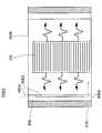
- FIG. 5 is a diagram illustrating a fuel cell device FCB according to the second embodiment of the present disclosure.
- the fuel cell device FCB differs from the fuel cell device FC only in the mode of the air heating channel 40B having the air channel 401B and the air channel 403B, and the gas exhaust channel 41B including the exhaust gas channel 411B and the exhaust gas channel 412B. ing.
- the flow path width of the air flow path 401B is configured to be narrower than the flow path width of the air flow path 403B. Therefore, more heat is received from the gas discharge channel 41 while flowing through the air channel 401B than during flowing through the air channel 403B. Therefore, the temperature rise amount of the air flowing through the air flow path 401B is larger than the temperature rise amount of the air flowing through the air flow path 403B.
- the exhaust gas flow channel 412B is configured to have a narrower channel width than the exhaust gas flow channel 411B. With this configuration, heat exchange between the exhaust gas flow path 412B and the air flow path 401B is promoted, and the temperature increase amount of the air flowing through the air flow path 401B is the temperature increase of the air flowing through the air flow path 403B. Larger than the amount.
- the temperature of the upper part tends to be lower than the temperature of the middle part and the lower part of the cell stack CS, and efficiently heated air passes from the air flow path 401B through the gap 402 to the air flow path 403B from above. Therefore, heat can be efficiently applied to the upper part of the cell stack CS.
- a gap is provided between the top plate 181 and the top plate 185, and the air heated by flowing through the air flow path 401B enters the gap, so the top of the cell stack CS. In contrast, heat can be efficiently applied.
- the heat return portion is configured by folding the air heating flow path 40B.
- the air heating channel 40B has an air channel 401B and an air channel 403B.
- An inflow port 401Ba is provided at the lower end (one end side) of the air flow path 401B.
- the upper end of the air channel 401B is connected to the upper end of the air channel 403B.
- An outlet 403Bb is provided at the lower end (the other end side) of the air flow path 403B.
- the air flowing in from the inlet 401Ba flows from the air flow path 401B to the air flow path 403B, it receives heat from the gas discharge flow path 41B and the cell stack CS, and its temperature rises.
- the air flowing through the air flow paths 401B and 403B has the highest temperature in the vicinity of the outlet 403Bb. Since the inflow port 403Bb and the inflow port 401Ba are arranged close to each other, the heat transfer HF is generated from the high-temperature air in the vicinity of the outflow port 403Bb to the low-temperature air in the vicinity of the inflow port 401Ba. Therefore, the heat return part 50B which returns the heat of the air in the other end side of the air heating flow path 40B to the air in the one end side is formed.
- FIG. 8 shows a flow path configuration according to the third embodiment.
- the air heating flow path 40D is composed of an air flow path 401D and an air flow path 403D.
- the gas discharge channel 41D is configured by an exhaust gas channel 411D and an exhaust gas channel 412D.
- the air channel 401D and the air channel 403D are channels having the same width.
- the exhaust gas channel 411D and the exhaust gas channel 412D are channels having the same width.
- the inflow port 401Da is provided at the lower end (one end side) of the air flow path 401D.
- the upper end of the air flow path 401D is connected to the upper end of the air flow path 403D.
- An outlet 403Db is provided at the lower end (the other end side) of the air flow path 403D.
- the air flowing in from the inlet 401Da flows from the air flow path 401D to the air flow path 403D, it receives heat from the gas discharge flow path 41D and the cell stack CS, and the temperature rises.
- the air flowing through the air flow paths 401D and 403D has the highest temperature in the vicinity of the outlet 403Db. Since the inflow port 403Db and the inflow port 401Da are arranged close to each other, the heat transfer HF is generated from the high-temperature air in the vicinity of the outflow port 403Db to the low-temperature air in the vicinity of the inflow port 401Da. Therefore, the heat return part 50D which returns the heat of the air in the other end side of the air heating flow path 40D to the air in the one end side is formed.
- FIG. 9 shows a flow path configuration according to the fourth embodiment.
- neither the air heating flow path 40E nor the gas discharge flow path 41E has a folded structure, and both are configured as straight pipe lines.
- An inlet 40Ea is provided at the upper end (one end side) of the air heating channel 40E.
- An outlet 40Eb is provided at the lower end (the other end side) of the air heating channel 40E.
- the air flowing in from the inlet 40Ea receives heat from the gas discharge channel 41D and the cell stack CS while flowing through the air heating channel 40E, and its temperature rises.
- the temperature of the air flowing through the air heating channel 40E is highest near the outlet 40Eb.
- the heat return part 50E which returns the heat of the air in the other end side of the air heating flow path 40E to the air in the one end side of the air heating flow path 40E is provided. Therefore, heat transfer HF is generated from the high-temperature air near the outlet 40Eb to the low-temperature air near the inlet 40Ea.
- FIG. 10 shows a specific example of the heat return unit 50E.
- the heat return unit 50E1 shown in FIG. 10 includes a pump 50E1a and a heat return pipe 50E1b.
- the heat return pipe 50E1b connects the upper end side (one end side) and the lower end side (the other end side) of the air heating flow path 40E.
- the pump 50E1a is provided in the middle of the heat return pipe 50E1b.
- the pump 50E1a is driven, high-temperature air on the lower end side (the other end side) of the air heating flow path 40E can be sent to the upper end side (one end side). Therefore, heat transfer HF is generated from the high-temperature air near the outlet 40Eb to the low-temperature air near the inlet 40Ea.
- FIG. 11 shows a specific example of the heat return unit 50E.
- the heat return unit 50E2 shown in FIG. 11 is configured by a heat pipe.
- a working fluid is sealed inside the heat return unit 50E2.
- the heat return unit 50E2 is provided from the upper end side (one end side) to the lower end side (the other end side) of the air heating flow path 40E.
- the temperature of the lower end side (the other end side) of the heat return unit 50E2 is increased by the high temperature air.
- the temperature of the working fluid sealed inside also rises and convects to the upper end side (one end side).
- the heat return part 50E2 is comprised by a heat pipe, the heat
Landscapes
- Engineering & Computer Science (AREA)
- Chemical & Material Sciences (AREA)
- Life Sciences & Earth Sciences (AREA)
- Manufacturing & Machinery (AREA)
- Sustainable Development (AREA)
- Sustainable Energy (AREA)
- Chemical Kinetics & Catalysis (AREA)
- Electrochemistry (AREA)
- General Chemical & Material Sciences (AREA)
- Fuel Cell (AREA)
- Combustion & Propulsion (AREA)
Priority Applications (1)
| Application Number | Priority Date | Filing Date | Title |
|---|---|---|---|
| DE112015003788.8T DE112015003788B4 (de) | 2014-08-19 | 2015-08-06 | Brennstoffzellen-Einheit |
Applications Claiming Priority (4)
| Application Number | Priority Date | Filing Date | Title |
|---|---|---|---|
| JP2014-166527 | 2014-08-19 | ||
| JP2014166527 | 2014-08-19 | ||
| JP2015151575A JP6409710B2 (ja) | 2014-08-19 | 2015-07-31 | 燃料電池装置 |
| JP2015-151575 | 2015-07-31 |
Publications (1)
| Publication Number | Publication Date |
|---|---|
| WO2016027430A1 true WO2016027430A1 (ja) | 2016-02-25 |
Family
ID=55350399
Family Applications (1)
| Application Number | Title | Priority Date | Filing Date |
|---|---|---|---|
| PCT/JP2015/003958 Ceased WO2016027430A1 (ja) | 2014-08-19 | 2015-08-06 | 燃料電池装置 |
Country Status (3)
| Country | Link |
|---|---|
| JP (1) | JP6409710B2 (enExample) |
| DE (1) | DE112015003788B4 (enExample) |
| WO (1) | WO2016027430A1 (enExample) |
Cited By (1)
| Publication number | Priority date | Publication date | Assignee | Title |
|---|---|---|---|---|
| JP2017183131A (ja) * | 2016-03-31 | 2017-10-05 | Toto株式会社 | 固体酸化物形燃料電池装置 |
Families Citing this family (2)
| Publication number | Priority date | Publication date | Assignee | Title |
|---|---|---|---|---|
| WO2017221790A1 (ja) * | 2016-06-20 | 2017-12-28 | 京セラ株式会社 | 燃料電池モジュールおよび燃料電池装置 |
| JP6519807B2 (ja) * | 2016-07-28 | 2019-05-29 | Toto株式会社 | 固体酸化物形燃料電池装置 |
Citations (5)
| Publication number | Priority date | Publication date | Assignee | Title |
|---|---|---|---|---|
| US20050123808A1 (en) * | 2003-12-05 | 2005-06-09 | Siemens Westinghouse Power Corporation | Integral air preheater and start-up heating means for solid oxide fuel cell power generators |
| JP2007287424A (ja) * | 2006-04-14 | 2007-11-01 | Honda Motor Co Ltd | 燃料電池システム |
| WO2009119616A1 (ja) * | 2008-03-26 | 2009-10-01 | 京セラ株式会社 | 改質器、セルスタック装置および燃料電池モジュールならびに燃料電池装置 |
| JP2013114853A (ja) * | 2011-11-28 | 2013-06-10 | Aisin Seiki Co Ltd | 燃料電池装置 |
| JP2014086180A (ja) * | 2012-10-19 | 2014-05-12 | Osaka Gas Co Ltd | 燃焼装置 |
Family Cites Families (2)
| Publication number | Priority date | Publication date | Assignee | Title |
|---|---|---|---|---|
| JP2010027215A (ja) * | 2008-07-15 | 2010-02-04 | Nissan Motor Co Ltd | 燃料電池 |
| JP6229611B2 (ja) * | 2014-07-22 | 2017-11-15 | 株式会社デンソー | 燃料電池装置 |
-
2015
- 2015-07-31 JP JP2015151575A patent/JP6409710B2/ja active Active
- 2015-08-06 DE DE112015003788.8T patent/DE112015003788B4/de active Active
- 2015-08-06 WO PCT/JP2015/003958 patent/WO2016027430A1/ja not_active Ceased
Patent Citations (5)
| Publication number | Priority date | Publication date | Assignee | Title |
|---|---|---|---|---|
| US20050123808A1 (en) * | 2003-12-05 | 2005-06-09 | Siemens Westinghouse Power Corporation | Integral air preheater and start-up heating means for solid oxide fuel cell power generators |
| JP2007287424A (ja) * | 2006-04-14 | 2007-11-01 | Honda Motor Co Ltd | 燃料電池システム |
| WO2009119616A1 (ja) * | 2008-03-26 | 2009-10-01 | 京セラ株式会社 | 改質器、セルスタック装置および燃料電池モジュールならびに燃料電池装置 |
| JP2013114853A (ja) * | 2011-11-28 | 2013-06-10 | Aisin Seiki Co Ltd | 燃料電池装置 |
| JP2014086180A (ja) * | 2012-10-19 | 2014-05-12 | Osaka Gas Co Ltd | 燃焼装置 |
Cited By (1)
| Publication number | Priority date | Publication date | Assignee | Title |
|---|---|---|---|---|
| JP2017183131A (ja) * | 2016-03-31 | 2017-10-05 | Toto株式会社 | 固体酸化物形燃料電池装置 |
Also Published As
| Publication number | Publication date |
|---|---|
| DE112015003788T5 (de) | 2017-05-04 |
| JP6409710B2 (ja) | 2018-10-24 |
| DE112015003788B4 (de) | 2025-05-08 |
| JP2016046247A (ja) | 2016-04-04 |
Similar Documents
| Publication | Publication Date | Title |
|---|---|---|
| TWI357682B (enExample) | ||
| JP6101781B2 (ja) | 燃料電池モジュール | |
| TW200919815A (en) | Fuel cell apparatus | |
| JP2017105695A (ja) | 水素生成装置及び燃料電池システム | |
| JP6640962B2 (ja) | 改質器、セルスタック装置、燃料電池モジュールおよび燃料電池装置 | |
| JP6409710B2 (ja) | 燃料電池装置 | |
| JP6331973B2 (ja) | 燃料電池装置 | |
| JP6229611B2 (ja) | 燃料電池装置 | |
| JP5907751B2 (ja) | 固体酸化物形燃料電池 | |
| JP2018120653A (ja) | 燃料電池装置 | |
| JP7215032B2 (ja) | 燃料電池装置 | |
| JP6613933B2 (ja) | 燃料電池装置 | |
| JP6405900B2 (ja) | 燃料電池装置 | |
| JP5244488B2 (ja) | 燃料電池用改質器 | |
| JP5959222B2 (ja) | 固体酸化物形燃料電池 | |
| JP6379789B2 (ja) | 燃料電池装置 | |
| JP6177359B2 (ja) | 固体酸化物形燃料電池 | |
| JP2016152075A (ja) | 燃料電池装置 | |
| JP2021086713A (ja) | 燃料電池モジュール | |
| JP2016023106A (ja) | 蒸発器及びこれを備えた燃料電池装置 | |
| JP6331965B2 (ja) | 燃料電池装置 | |
| JP6398557B2 (ja) | 燃料電池装置 | |
| JP6277898B2 (ja) | 燃料電池装置 | |
| JP2016130195A (ja) | 水素生成装置 | |
| JP6175010B2 (ja) | 燃料電池モジュール |
Legal Events
| Date | Code | Title | Description |
|---|---|---|---|
| 121 | Ep: the epo has been informed by wipo that ep was designated in this application |
Ref document number: 15833115 Country of ref document: EP Kind code of ref document: A1 |
|
| WWE | Wipo information: entry into national phase |
Ref document number: 112015003788 Country of ref document: DE |
|
| 122 | Ep: pct application non-entry in european phase |
Ref document number: 15833115 Country of ref document: EP Kind code of ref document: A1 |
|
| WWG | Wipo information: grant in national office |
Ref document number: 112015003788 Country of ref document: DE |