WO2016017470A1 - 切削インサート、切削工具及び切削加工物の製造方法 - Google Patents
切削インサート、切削工具及び切削加工物の製造方法 Download PDFInfo
- Publication number
- WO2016017470A1 WO2016017470A1 PCT/JP2015/070673 JP2015070673W WO2016017470A1 WO 2016017470 A1 WO2016017470 A1 WO 2016017470A1 JP 2015070673 W JP2015070673 W JP 2015070673W WO 2016017470 A1 WO2016017470 A1 WO 2016017470A1
- Authority
- WO
- WIPO (PCT)
- Prior art keywords
- cutting edge
- rake face
- corner
- rake
- cutting
- Prior art date
- Legal status (The legal status is an assumption and is not a legal conclusion. Google has not performed a legal analysis and makes no representation as to the accuracy of the status listed.)
- Ceased
Links
Images








Classifications
-
- B—PERFORMING OPERATIONS; TRANSPORTING
- B23—MACHINE TOOLS; METAL-WORKING NOT OTHERWISE PROVIDED FOR
- B23B—TURNING; BORING
- B23B27/00—Tools for turning or boring machines; Tools of a similar kind in general; Accessories therefor
- B23B27/04—Cutting-off tools
- B23B27/045—Cutting-off tools with chip-breaking arrangements
-
- B—PERFORMING OPERATIONS; TRANSPORTING
- B23—MACHINE TOOLS; METAL-WORKING NOT OTHERWISE PROVIDED FOR
- B23B—TURNING; BORING
- B23B27/00—Tools for turning or boring machines; Tools of a similar kind in general; Accessories therefor
- B23B27/14—Cutting tools of which the bits or tips or cutting inserts are of special material
-
- B—PERFORMING OPERATIONS; TRANSPORTING
- B23—MACHINE TOOLS; METAL-WORKING NOT OTHERWISE PROVIDED FOR
- B23B—TURNING; BORING
- B23B27/00—Tools for turning or boring machines; Tools of a similar kind in general; Accessories therefor
- B23B27/14—Cutting tools of which the bits or tips or cutting inserts are of special material
- B23B27/141—Specially shaped plate-like cutting inserts, i.e. length greater or equal to width, width greater than or equal to thickness
- B23B27/143—Specially shaped plate-like cutting inserts, i.e. length greater or equal to width, width greater than or equal to thickness characterised by having chip-breakers
-
- B—PERFORMING OPERATIONS; TRANSPORTING
- B23—MACHINE TOOLS; METAL-WORKING NOT OTHERWISE PROVIDED FOR
- B23B—TURNING; BORING
- B23B27/00—Tools for turning or boring machines; Tools of a similar kind in general; Accessories therefor
- B23B27/22—Cutting tools with chip-breaking equipment
-
- B—PERFORMING OPERATIONS; TRANSPORTING
- B23—MACHINE TOOLS; METAL-WORKING NOT OTHERWISE PROVIDED FOR
- B23B—TURNING; BORING
- B23B2200/00—Details of cutting inserts
- B23B2200/04—Overall shape
- B23B2200/0447—Parallelogram
- B23B2200/0452—Parallelogram rounded
-
- B—PERFORMING OPERATIONS; TRANSPORTING
- B23—MACHINE TOOLS; METAL-WORKING NOT OTHERWISE PROVIDED FOR
- B23B—TURNING; BORING
- B23B2200/00—Details of cutting inserts
- B23B2200/08—Rake or top surfaces
- B23B2200/081—Rake or top surfaces with projections
-
- B—PERFORMING OPERATIONS; TRANSPORTING
- B23—MACHINE TOOLS; METAL-WORKING NOT OTHERWISE PROVIDED FOR
- B23B—TURNING; BORING
- B23B2200/00—Details of cutting inserts
- B23B2200/08—Rake or top surfaces
- B23B2200/086—Rake or top surfaces with one or more grooves
- B23B2200/087—Rake or top surfaces with one or more grooves for chip breaking
-
- B—PERFORMING OPERATIONS; TRANSPORTING
- B23—MACHINE TOOLS; METAL-WORKING NOT OTHERWISE PROVIDED FOR
- B23B—TURNING; BORING
- B23B2200/00—Details of cutting inserts
- B23B2200/28—Angles
- B23B2200/286—Positive cutting angles
-
- B—PERFORMING OPERATIONS; TRANSPORTING
- B23—MACHINE TOOLS; METAL-WORKING NOT OTHERWISE PROVIDED FOR
- B23B—TURNING; BORING
- B23B2200/00—Details of cutting inserts
- B23B2200/32—Chip breaking or chip evacuation
- B23B2200/321—Chip breaking or chip evacuation by chip breaking projections
-
- B—PERFORMING OPERATIONS; TRANSPORTING
- B23—MACHINE TOOLS; METAL-WORKING NOT OTHERWISE PROVIDED FOR
- B23B—TURNING; BORING
- B23B2200/00—Details of cutting inserts
- B23B2200/32—Chip breaking or chip evacuation
- B23B2200/323—Chip breaking or chip evacuation by chip breaking depressions
-
- B—PERFORMING OPERATIONS; TRANSPORTING
- B23—MACHINE TOOLS; METAL-WORKING NOT OTHERWISE PROVIDED FOR
- B23B—TURNING; BORING
- B23B27/00—Tools for turning or boring machines; Tools of a similar kind in general; Accessories therefor
- B23B27/14—Cutting tools of which the bits or tips or cutting inserts are of special material
- B23B27/141—Specially shaped plate-like cutting inserts, i.e. length greater or equal to width, width greater than or equal to thickness
Definitions
- This aspect relates to a cutting insert, a cutting tool, and a manufacturing method of a cut product using the cutting insert.
- Cutting inserts disclosed in International Publication No. 2011/037186 (Patent Document 1) and Japanese Patent Application Laid-Open No. 2010-69614 (Patent Document 2) are known as cutting inserts used in turning.
- the rake face extending along the cutting edge has a first region and a second region.
- the rake angle of the second region is larger than the rake angle of the first region.
- the cutting insert disclosed in Patent Document 2 has a recess formed between a cutting edge (corner cutting edge) located at an upper corner portion and a projection on the upper surface.
- This aspect is made in view of the above problems, and provides a cutting insert capable of stably discharging chips even when the amount of cutting is changed in the cutting process using the corner portion. is there.
- a cutting insert according to an aspect is provided in the corner portion and an upper surface having a pair of sides adjacent to the corner portion, a lower surface, a side surface located between the upper surface and the lower surface, and the corner portion. It has a corner cutting edge.
- the upper surface includes a first rake face positioned along the corner cutting edge, a raised portion that is located on the inner side of the first rake face and is raised upward, the corner cutting edge, and the raised edge. And a second rake face recessed with respect to the first rake face.
- the rake angle in the first region corresponding to the center of the corner cutting edge in the second rake surface is located on the side of the first region in the second rake surface. It is characterized by being larger than the rake angle in two regions.
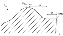
- FIG. 6 is a cross-sectional view of the B1-B1 cross section in the cutting insert shown in FIG. 6 is a cross-sectional view taken along B2-B2 in the cutting insert shown in FIG. FIG.
- FIG. 6 is a cross-sectional view of a B3-B3 cross section in the cutting insert shown in FIG. 5.
- FIG. 6 is a cross-sectional view of a B4-B4 cross section in the cutting insert shown in FIG. 5.
- It is the schematic which shows 1 process of the manufacturing method of the cut workpiece of one Embodiment of this invention. It is the schematic which shows 1 process of the manufacturing method of the cut workpiece of one Embodiment of this invention. It is the schematic which shows 1 process of the manufacturing method of the cut workpiece of one Embodiment of this invention. It is the schematic which shows 1 process of the manufacturing method of the cut workpiece of one
- the cutting insert of one embodiment is explained in detail using a drawing.
- the drawings referred to below for convenience of explanation, among the constituent members of the embodiment, only the main members necessary for explaining the present invention are shown in a simplified manner. Therefore, the cutting insert of the present invention may include any constituent member that is not shown in the referenced drawings.
- the dimension of the member in each figure does not represent the dimension of an actual structural member, the dimension ratio of each member, etc. faithfully.
- a cutting insert 1 (hereinafter also simply referred to as an insert 1) according to an embodiment will be described with reference to FIGS.
- the insert 1 of this embodiment includes an upper surface 3, a lower surface 5, a side surface 7, a cutting edge 9, and a through hole 11.
- Examples of the material of the insert 1 include cemented carbide or cermet.
- composition of the cemented carbide examples include WC—Co, WC—TiC—Co, and WC—TiC—TaC—Co.
- WC—Co is produced by adding cobalt (Co) powder to tungsten carbide (WC) and sintering.
- WC—TiC—Co is obtained by adding titanium carbide (TiC) to WC—Co.
- WC—TiC—TaC—Co is obtained by adding tantalum carbide (TaC) to WC—TiC—Co.
- cermet is a sintered composite material in which a metal is combined with a ceramic component.
- an example of the cermet is mainly composed of a titanium compound such as titanium carbide (TiC) or titanium nitride (TiN).
- the surface of the member constituting the insert 1 may be coated with a film using a chemical vapor deposition (CVD) method or a physical vapor deposition (PVD) method.
- CVD chemical vapor deposition
- PVD physical vapor deposition
- the composition of the coating include titanium carbide (TiC), titanium nitride (TiN), titanium carbonitride (TiCN), and alumina (Al 2 O 3 ).
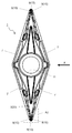
- the upper surface 3 When viewed from above, the upper surface 3 has a polygonal shape, and as shown in FIG. 2, in the present embodiment, has a rhombus shape.
- the rhombus upper surface 3 has a corner portion and a pair of side portions. Each of the pair of side portions is adjacent to the corner portion. That is, the pair of side portions are positioned so as to sandwich the corner portion therebetween.
- the polygonal shape does not mean strictly a polygonal shape.
- the corner portion on the upper surface 3 in the present embodiment is not a strict corner, and has a rounded shape when viewed from the upper surface.
- the upper surface 3 in the present embodiment has two corner portions that are acute angles in a top view. For this reason, there are two pairs of side portions located so as to sandwich the corner portion therebetween.
- the number of acute corners may be one or two.
- the pair of sides are linear when viewed from above.
- the lower surface 5 is a surface located on the opposite side to the upper surface 3.
- the lower surface 5 functions as a seating surface for the insert pocket when the insert 1 is attached to the holder.
- the lower surface 5 in the present embodiment has a polygonal shape corresponding to the upper surface 3.
- the lower surface 5 has a rhombus shape like the upper surface 3, but is slightly smaller than the upper surface 3.
- the lower surface 5 may be the same size as the upper surface 3. In this case, the peripheral edge of the lower surface 5 overlaps with the peripheral edge of the upper surface 3 in a top view.
- the shape of the upper surface 3 and the lower surface 5 is not limited to the above form.
- the shapes of the upper surface 3 and the lower surface 5 are substantially square.
- the shape of the upper surface 3 and the lower surface 5 may be a polygonal shape such as a triangle or a pentagon.
- the upper surface 3 and the lower surface 5 in this embodiment are rhombuses.
- the quadrangular shape is not limited to a rhombus, and may be a parallelogram, for example.
- the width in the longitudinal direction (vertical direction in FIG. 2) of the upper surface 3 of the rhombus in the insert 1 of this embodiment is set to about 15 to 25 mm, for example. Further, the width in the direction orthogonal to the longitudinal direction (left-right direction in FIG. 2) is set to about 3 to 10 mm, for example.
- the longitudinal direction of the rhombus-shaped lower surface 5 and the width in the direction orthogonal to the longitudinal direction are set according to the size of the upper surface 3.
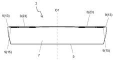
- the thickness of the insert 1 is set to about 3 to 7 mm, for example. At this time, the thickness refers to the height direction (up and down direction in FIG. 3) from the uppermost portion of the upper surface 3 to the lowermost portion of the lower surface 5 when the insert 1 is viewed from the side. It means width.
- the insert 1 of the present embodiment has a through hole 11 that penetrates from the center of the upper surface 3 to the center of the lower surface 5.
- the through hole 11 is provided to insert a screw when the insert 1 is fixed to the holder of the cutting tool with a screw.
- a clamp structure may be employed instead of the above-described method using screw fixing.
- the central axis O1 of the through hole 11 extends in the vertical direction. Therefore, in the following, a reference plane S1 that is orthogonal to the central axis O1 and is located between the upper surface 3 and the lower surface 5 is set.
- the reference plane S1 is used for evaluating the vertical position of each component in the insert 1 of the present embodiment.
- the reference surface S1 is positioned in parallel to the lower surface 5.
- the center of the upper surface 3 means the center of gravity on the upper surface 3.
- the intersection of the diagonal lines becomes the center of the upper surface 3.
- the center of the lower surface 5 means the center of gravity of the lower surface 5.
- the intersection of the diagonal lines becomes the center of the lower surface 5.
- the side surface 7 is located between the upper surface 3 and the lower surface 5 and is connected to the upper surface 3 and the lower surface 5. As described above, since the lower surface 5 is slightly smaller than the upper surface 3, the side surface 7 is inclined so as to approach the central axis O1 from the upper surface 3 side toward the lower surface 5 side.
- a cutting edge 9 is provided on the ridge line where the upper surface 3 and the side surface 7 intersect.
- the cutting edge 9 has a corner cutting edge 13 (main cutting edge) and a secondary cutting edge 15.
- the corner cutting edge 13 is provided at a corner portion on the upper surface 3.
- the auxiliary cutting edges 15 are respectively provided on a pair of sides on the upper surface 3. That is, the auxiliary cutting edge 15 in the present embodiment means a portion of the cutting edge 9 provided on a pair of sides on the upper surface 3.
- the corner cutting blade 13 has a rounded shape in a top view. Specifically, the corner cutting edge 13 has an arc shape convex outward. Further, the corner cutting edge 13 has a constant height in a side view.
- the auxiliary cutting edge 15 has a substantially linear shape when viewed from above. Further, the auxiliary cutting edge 15 has a portion inclined so as to approach the lower surface 5 as it is away from the corner cutting edge 13 in a side view.
- the sub cutting edge 15 is provided in a pair of side part in the upper surface 3, when it sees from the upper surface, it becomes a linear shape.
- the region where the upper surface 3 and the side surface 7 intersect and where the cutting edge 9 is provided may be subjected to a so-called honing process. That is, the ridgeline where the upper surface 3 and the side surface 7 intersect with each other may not be a strict line shape due to the intersection of two surfaces. If the above-mentioned ridgeline is a strict line shape, the strength of the cutting edge 9 is lowered. Therefore, R honing is performed in which this region has a curved surface shape.
- the insert 11 of this embodiment is a so-called single-sided insert 1 in which the cutting edge 9 is provided only on the ridgeline where the upper surface 3 and the side surface 7 intersect.
- the insert 1 may be a so-called double-sided insert in which a cutting edge is provided on a ridge line where the lower surface 5 and the side surface 7 intersect in addition to a ridge line where the upper surface 3 and the side surface 7 intersect. no problem.
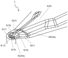
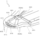
- the upper surface 3 in the present embodiment has a first rake surface 17, a second rake surface 19, a third rake surface 21, and a raised portion 23.
- the first rake face 17 is positioned along the corner cutting edge 13 in a top view, and is inclined downward as the distance from the corner cutting edge 13 increases.
- the second rake face 19 is located between the corner cutting edge 13 and the raised portion 23 in a top view. Since the first rake face 17 is located along the entire corner cutting edge 13, at least a part of the first rake face 17 is located between the corner cutting edge 13 and the second rake face 19. Yes. In the present embodiment, the second rake face 19 is positioned inside the first rake face 17. Therefore, the second rake face 19 is located between the first rake face 17 and the raised portion 23.
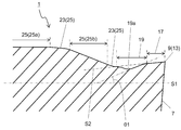
- the second rake face 19 is recessed with respect to the first rake face 17. That is, the second rake face 19 is a concave portion with respect to the first rake face 17. For this reason, the second rake face 19 is concave downward when the first rake face 17 is used as a reference. Specifically, when viewed in cross section, the second rake face 19 is positioned below the virtual extension line S2 obtained by extending the first rake face 17 toward the inside of the upper surface 3.
- the third rake face 21 is positioned along the auxiliary cutting edge 15 in a top view, and is inclined downward as the distance from the auxiliary cutting edge 15 increases.
- the width of the first rake face 17 indicated by the distance between the outer edge and the inner edge of the first rake face 17 in the direction perpendicular to the cutting edge 9 in a top view is set to about 0.08 to 0.25 mm. Is done.
- the width of the third rake face 21 indicated by the distance between the outer edge and the inner edge of the third rake face 21 in the direction orthogonal to the cutting edge 9 in a top view is 0.15 to 0.4 mm. Set to degree.
- the raised portion 23 is located on the inner side of the upper surface 3 with respect to the first rake face 17 and the third rake face 21, and is raised upward.
- the raised portion 23 is a portion that curves the chips that have passed through the first rake face 17 and the second rake face 19. In addition, it protrudes upward means the state provided so that the height from the reference plane S1 may become higher than the lower end of the 1st rake face 17 and the 3rd rake face 21. .
- the raised portion 23 in the present embodiment has a tip portion 25 positioned so as to include the bisector L of the corner portion.
- the tip 25 is positioned on the bisector L of the corner so as to include the bisector L of the corner. Further, the tip 25 protrudes toward the corner cutting edge 13.
- the tip portion 25 is positioned closer to the corner portion than the upper surface portion 25a parallel to the reference surface S1 and the upper surface portion 25a. And it has the front end surface part 25b which inclines below as it approaches a corner part.
- the upper surface portion 25 a is provided at a position higher than the cutting edge 9. Further, the tip surface portion 25b is a flat inclined surface.
- the upper surface 3 has the second rake face 19 positioned inside at least a part of the first rake face 17 as described above. Therefore, when cutting is performed using the corner cutting edge 13, when the feed is low and the thickness of the chip is thin, the chip is drawn into the second rake face 19, so that the chip can be bent stably. it can.
- the chip contacts the raised portion 23 without contacting the second rake face 19.
- the 2nd rake face 19 which is a hollow shape does not become obstructive when a thick chip advances.
- the chips do not contact the second rake face 19, the area of the upper surface 3 where the chips contact can be reduced. Therefore, it is possible to suppress the frictional heat generated with the contact of chips.
- the second rake face 19 is inclined so as to incline downward as the distance from the corner cutting edge 13 increases. have.
- the inclination angle of the inclined surface with respect to the reference surface S ⁇ b> 1 is the rake angle of the second rake surface 19. If the inclination angle of the inclined surface with respect to the reference surface S1 is not constant in one cross section, the maximum value of the inclination angle with respect to the reference surface S1 is set as the rake angle of the second rake surface 19. Since the second rake face 19 is recessed with respect to the first rake face 17, the rake angle of the second rake face 19 is larger than the rake angle of the first rake face 17.
- an area corresponding to the center of the corner cutting edge 13 on the second rake face 19 (hereinafter referred to as a first area for convenience) and a second located on the side of the first area on the second rake face 19.
- the area and rake angle are not the same value.
- the rake angle in the first region on the second rake surface 19 is larger than the rake angle in the second region on the second rake surface 19.
- the rake angle ⁇ 1 in the first region and the rake angle ⁇ 2 in the region corresponding to both ends of the corner cutting edge 13 in the second region are not the same value.
- the rake angle ⁇ 1 in the first region of the second rake face 19 is larger than the rake angle ⁇ 2 in the end region.
- the chip can be stably curved in the first region of the second rake face 19.
- the traveling direction of the chips drawn into the first region and the traveling direction of the chips drawn into the second region are different from each other. For this reason, if the rake angle of the second region is large and the chips drawn into the second region are also greatly curved, the traveling direction of the chips tends to become unstable.
- the chips drawn into the first region are greatly curved, while the chips drawn into the second region are curved slightly. Therefore, the chips drawn into the second region are easily pulled by the chips drawn into the first region, and the chip discharge direction is stabilized.
- the cut amount is large or small. Even so, chips can be discharged stably.
- the second rake face 19 preferably has a rake angle that decreases from the first area toward the end area in the second area. That is, it is preferable that the rake angle of the second rake face 19 becomes smaller in the second area from the area close to the first area toward the end area.
- the end region means a region corresponding to both end portions of the corner cutting edge 13 in the second region.
- the rake angle when the rake angle is measured in a region located between the first region and the end region, the rake angle is smaller than the rake angle ⁇ 1 in the first region, and the end portion It is larger than the rake angle ⁇ 2 in the region.
- the second rake face 19 has a height from the lower surface 5 at the lower end that increases from the region adjacent to the first region toward the end region.
- this height is higher than the height of the lower end in the first region. High and smaller than the height of the lower end in the end region.
- the width W1 of the corner cutting edge 13 in the direction perpendicular to the bisector L of the corner cutting edge 13 when viewed from above is larger than the width W2 of the second rake face 19.
- Chips generated by the auxiliary cutting edge 15 flow on the third rake face 21.
- the sub cutting edge 15 is formed in a pair of side part which is a substantially linear shape as above-mentioned. Therefore, the traveling direction of the chips generated by the auxiliary cutting edge 15 is easily stabilized.
- the tip when viewed from the top, advances from the boundary portion between the corner cutting edge 13 and the auxiliary cutting edge 15 to the inside of the top surface and in a direction perpendicular to the cutting edge 9 at the boundary portion.
- the end of the second rake face 19 is located. Therefore, it is possible to avoid the chips generated by the auxiliary cutting edge 15 from entering the second rake face 19 while the chips generated by the corner cutting edge 13 are more reliably advanced to the second rake face 19.
- the corner cutting edge 13 has a convex curve shape and the secondary cutting edge 15 has a linear shape
- the boundary portion between the corner cutting edge 13 and the secondary cutting edge 15 is a curved portion from the straight line portion of the cutting edge. It means the part that changes to.
- the bottom of the second rake face 19 has a concave curve shape.
- the bottom of the second rake face 19 may be a flat surface, as shown in FIG. 7, when the bottom of the second rake face 19 has a concave curve shape, the chips are stabilized along the bottom. Easier to proceed. Therefore, it is possible to bend the chips stably.
- the second rake face 19 in the present embodiment has a convex curve shape toward the corner cutting edge 13 at a portion facing the corner cutting edge 13 on the outer peripheral edge when viewed from above.
- variety of the 1st rake face 17 located between the corner cutting edge 13 and the 2nd rake face 19 can be suppressed. Therefore, variation in timing at which chips generated in each region of the corner cutting edge 13 proceed to the second rake face 19 is suppressed. Therefore, the chips can be smoothly advanced to the second rake face 19.
- the above portion when viewed from above, is not simply a convex curve shape, but an arc shape.
- region of the corner cutting edge 13 advances to the 2nd rake face 19 can further be suppressed.
- the rake angle ⁇ 1 in the first region of the second rake surface 19 is larger than the rake angle in the second region of the second rake surface 19, while the rake of the first rake surface 17 is.
- the angle is constant from a position corresponding to the center of the corner cutting edge 13 to a position corresponding to both ends of the corner cutting edge 13.
- the second rake face 19 is located on the inner side of the first rake face 17 and is connected to the raised portion 23. Thereby, the chips passing through the second rake face 19 can be smoothly brought into contact with the raised portion 23. Therefore, chips can be favorably curved at the raised portion 23.
- the present invention is not limited to this configuration, and the second rake face 19 may not be connected to the raised portion 23. 11 and 12, the second rake face 19 is located surrounded by the first rake face 17, and the second rake face 19 is separated from the raised portion 23.
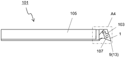
- the cutting tool 101 of this embodiment includes a holder 105 having an insert pocket 103 (hereinafter also simply referred to as a pocket 103) on the tip side, and a corner cutting edge 13 protruding from the tip of the holder 105.
- the cutting insert 1 mounted in the pocket 103 is provided.
- the holder 105 has an elongated bar shape.
- One pocket 103 is provided on the tip side of the holder 105.
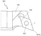
- the pocket 103 is a portion to which the insert 1 is attached, and is open to the front end surface of the holder 105. At this time, since the pocket 103 is also open to the side surface of the holder 105, the insert 1 can be easily mounted.
- the pocket 103 has a seating surface parallel to the lower surface of the holder 105 and a constraining side surface inclined with respect to the seating surface.
- the insert 1 is installed in the pocket 103.
- the insert 1 is mounted such that the corner cutting edge 13 protrudes from the tip of the holder 105.
- the insert 1 is attached to the holder 105 with a fixing screw 107. That is, the insert 1 is inserted into the holder 105 by inserting the fixing screw 107 into the through hole of the insert 1 and inserting the tip of the fixing screw 107 into the screw hole formed in the pocket 103 and screwing the screw portions together. It is installed.
- steel, cast iron or the like can be used.
- steel having high toughness among these members it is preferable to use steel having high toughness among these members.
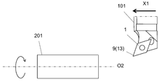
- the cut workpiece is produced by cutting the work material 201.
- the manufacturing method of the cut workpiece in the present embodiment includes the following steps. That is, (1) rotating the work material 201; (2) a step of bringing a corner cutting edge of the cutting tool 101 represented by the above embodiment into contact with the rotating work material 201; (3) a step of separating the cutting tool 101 from the work material 201; It has.
- the work material 201 is rotated around the axis O ⁇ b> 2, and the cutting tool 101 is relatively moved closer to the work material 201.
- the corner cutting edge of the cutting tool 101 is brought into contact with the rotating workpiece 201 to cut the workpiece 201.
- the cutting tool 101 is relatively moved away from the work material 201.
- the cutting tool 101 is moved in the X1 direction while the axis O2 is fixed and the workpiece 201 is rotated, thereby approaching the workpiece 201.
- the workpiece 201 is cut by bringing the corner cutting edge 13 in the cutting insert 1 into contact with the rotating workpiece 201.
- the cutting tool 101 is moved away in the X2 direction while the work material 201 is rotated.
- the cutting tool 101 is brought into contact with the work material 201 by moving the cutting tool 101 in each step, or the cutting tool 101 is separated from the work material 201.
- the cutting tool 101 is not limited to such a form.
- the work material 201 may be brought close to the cutting tool 101 in the step (1).
- the work material 201 may be moved away from the cutting tool 101.
- the state where the workpiece 201 is rotated and the corner cutting edge 13 in the cutting insert 1 is brought into contact with a different part of the workpiece 201 may be repeated.
- representative examples of the material of the work material 201 include carbon steel, alloy steel, stainless steel, cast iron, or non-ferrous metal.
- the present invention is not limited to the above-described embodiment, and it is needless to say that any embodiment can be used without departing from the gist of the present invention.
- Cutting insert DESCRIPTION OF SYMBOLS 3 ... Upper surface 5 ... Lower surface 7 ... Side surface 9 ... Cutting edge 11 ... Through-hole 13 ... Corner cutting edge 15 ... Sub cutting edge 17 ... 1st rake face 19 ... 2nd scoop surface 19a ... Bottom 21 ... 3rd scoop surface 23 ... Raised portion 25 ... Tip portion 25a ... Top surface portion 25b ... Tip surface portion 101 ... Cutting Tool 103 ... Insert pocket (pocket) 105 ... Holder 107 ... Fixing screw 201 ... Work material
Landscapes
- Engineering & Computer Science (AREA)
- Mechanical Engineering (AREA)
- Cutting Tools, Boring Holders, And Turrets (AREA)
Abstract
Description
以下、一実施形態の切削インサートについて、図面を用いて詳細に説明する。但し、以下で参照する各図は、説明の便宜上、実施形態の構成部材のうち、本発明を説明するために必要な主要部材のみを簡略化して示したものである。従って、本発明の切削インサートは、参照する各図に示されていない任意の構成部材を備え得る。また、各図中の部材の寸法は、実際の構成部材の寸法及び各部材の寸法比率等を忠実に表したものではない。
次に、本発明の一実施形態の切削工具101について図面を用いて説明する。
次に、本発明の一実施形態の切削加工物の製造方法について図面を用いて説明する。
(1)被削材201を回転させる工程と、
(2)回転している被削材201に上記実施形態に代表される切削工具101のコーナ切刃を接触させる工程と、
(3)切削工具101を被削材201から離す工程と、
を備えている。
3・・・上面
5・・・下面
7・・・側面
9・・・切刃
11・・・貫通孔
13・・・コーナ切刃
15・・・副切刃
17・・・第1すくい面
19・・・第2すくい面
19a・・・底部
21・・・第3すくい面
23・・・隆起部
25・・・先端部
25a・・・上面部分
25b・・・先端面部分
101・・・切削工具
103・・・インサートポケット(ポケット)
105・・・ホルダ
107・・・固定ネジ
201・・・被削材
Claims (11)
- コーナ部及び該コーナ部にそれぞれ隣接する一対の辺部を有する上面と、下面と、前記上面及び前記下面の間に位置する側面と、前記コーナ部に設けられたコーナ切刃とを備え、
前記上面は、前記コーナ切刃に沿って位置する第1すくい面と、該第1すくい面よりも内側に位置しており、上方に向かって隆起する隆起部と、前記コーナ切刃と前記隆起部との間に位置して、前記第1すくい面に対して窪んだ第2すくい面と、を有し、
前記第2すくい面における前記コーナ切刃の中心に対応する第1領域でのすくい角が、前記第2すくい面における前記第1領域の側方に位置する第2領域でのすくい角よりも大きいことを特徴とする切削インサート。 - 前記第2すくい面は、前記第1領域から前記第2領域における前記コーナ切刃の両端部に対応する端部領域に向かうにしたがってすくい角が小さくなっていることを特徴とする請求項1に記載の切削インサート。
- 上面視した場合に、前記コーナ切刃の二等分線に直交する方向における前記コーナ切刃及び前記第2すくい面の幅は、前記コーナ切刃の前記幅が前記第2すくい面の前記幅よりも大きいことを特徴とする請求項1又は2に記載の切削インサート。
- 前記上面における前記辺部に設けられた副切刃をさらに有し、
上面視した場合に、前記第2すくい面の端部は、前記コーナ切刃と前記副切刃との境界部分から、前記上面の内側であって前記境界部分における前記切刃に直交する方向に進んだ先に位置していることを特徴とする請求項3に記載の切削インサート。 - 上面視した場合に、前記第2すくい面の外周縁における前記コーナ切刃と対向する部分が、前記コーナ切刃に向かって凸曲線形状であることを特徴とする請求項1~4のいずれか1つに記載の切削インサート。
- 上面視した場合に、前記第2すくい面の外周縁における前記コーナ切刃と対向する部分が、円弧形状であることを特徴とする請求項5に記載の切削インサート。
- 前記コーナ切刃に直交し、前記コーナ切刃の二等分線を含む断面において、前記第2すくい面の底部が凹曲線形状であることを特徴とする請求項1~6のいずれか1つに記載の切削インサート。
- 前記第2すくい面は、前記コーナ切刃の中心に対応する位置から前記コーナ切刃の両端部に対応する位置に向かうにしたがって下端の前記下面からの高さが高くなっていることを特徴とする請求項1~7のいずれか1つに記載の切削インサート。
- 前記第1すくい面のすくい角は、前記コーナ切刃の中心に対応する位置から前記コーナ切刃の両端部に対応する位置にかけて一定であることを特徴とする請求項1~8のいずれか1つに記載の切削インサート。
- 先端側にインサートポケットを有するホルダと、
前記コーナ切刃が前記ホルダの先端から突出するように前記インサートポケットに装着された、請求項1~9のいずれか1つに記載の切削インサートとを具備した切削工具。 - 被削材を回転させる工程と、
回転している前記被削材に請求項10に記載の切削工具における前記コーナ切刃を接触させる工程と、
回転している前記被削材から前記切削工具を離す工程とを備えた切削加工物の製造方法。
Priority Applications (2)
| Application Number | Priority Date | Filing Date | Title |
|---|---|---|---|
| JP2016538279A JP6645964B2 (ja) | 2014-07-29 | 2015-07-21 | 切削インサート、切削工具及び切削加工物の製造方法 |
| US15/329,732 US10099294B2 (en) | 2014-07-29 | 2015-07-21 | Cutting insert, cutting tool, and method for manufacturing machined product |
Applications Claiming Priority (2)
| Application Number | Priority Date | Filing Date | Title |
|---|---|---|---|
| JP2014-153501 | 2014-07-29 | ||
| JP2014153501 | 2014-07-29 |
Publications (1)
| Publication Number | Publication Date |
|---|---|
| WO2016017470A1 true WO2016017470A1 (ja) | 2016-02-04 |
Family
ID=55217373
Family Applications (1)
| Application Number | Title | Priority Date | Filing Date |
|---|---|---|---|
| PCT/JP2015/070673 Ceased WO2016017470A1 (ja) | 2014-07-29 | 2015-07-21 | 切削インサート、切削工具及び切削加工物の製造方法 |
Country Status (3)
| Country | Link |
|---|---|
| US (1) | US10099294B2 (ja) |
| JP (1) | JP6645964B2 (ja) |
| WO (1) | WO2016017470A1 (ja) |
Cited By (8)
| Publication number | Priority date | Publication date | Assignee | Title |
|---|---|---|---|---|
| US9849514B2 (en) * | 2013-05-28 | 2017-12-26 | Kyocera Corporation | Cutting insert and cutting tool, and method for producing cut workpieces using cutting tool |
| US20190168310A1 (en) * | 2016-07-28 | 2019-06-06 | Kyocera Corporation | Cutting insert, cutting tool, and method of manufacturing machined product |
| JP6648392B1 (ja) * | 2018-09-06 | 2020-02-14 | 住友電工ハードメタル株式会社 | 切削インサート |
| JPWO2021005951A1 (ja) * | 2019-07-08 | 2021-01-14 | ||
| WO2021095520A1 (ja) * | 2019-11-13 | 2021-05-20 | 京セラ株式会社 | 切削インサート、切削工具及び切削加工物の製造方法 |
| JP2021522074A (ja) * | 2018-04-26 | 2021-08-30 | アクチボラグ サンドビック コロマント | 旋削インサート |
| JPWO2021241623A1 (ja) * | 2020-05-26 | 2021-12-02 | ||
| CN114951768A (zh) * | 2021-02-24 | 2022-08-30 | 株式会社电装 | 旋转切削工具 |
Families Citing this family (9)
| Publication number | Priority date | Publication date | Assignee | Title |
|---|---|---|---|---|
| JP6315350B2 (ja) * | 2015-10-23 | 2018-04-25 | 住友電工ハードメタル株式会社 | 回転切削工具 |
| JP6035697B1 (ja) * | 2015-12-24 | 2016-11-30 | 株式会社タンガロイ | 切削インサートおよび切削工具 |
| US11077502B2 (en) * | 2016-06-17 | 2021-08-03 | Kyocera Corporation | Cutting insert, cutting tool, and method of manufacturing machined product |
| EP3260225B1 (en) * | 2016-06-20 | 2022-11-30 | Sandvik Intellectual Property AB | Turning insert |
| KR20180088637A (ko) * | 2016-12-20 | 2018-08-06 | 스미또모 덴꼬오 하드메탈 가부시끼가이샤 | 절삭 공구 및 그 제조 방법 |
| EP3476508A1 (en) * | 2017-10-31 | 2019-05-01 | Sandvik Intellectual Property AB | Turning insert |
| EP3702075B1 (en) | 2019-02-28 | 2023-12-20 | AB Sandvik Coromant | Turning insert for metal cutting |
| JP7041408B1 (ja) * | 2021-04-30 | 2022-03-24 | 株式会社タンガロイ | 切削インサート |
| USD1082874S1 (en) * | 2022-04-05 | 2025-07-08 | Sumitomo Electric Hardmetal Corp. | Cutting tool |
Citations (4)
| Publication number | Priority date | Publication date | Assignee | Title |
|---|---|---|---|---|
| US3395434A (en) * | 1966-06-01 | 1968-08-06 | Sandvikens Jernverks Ab | Cutting insert for chip cutting machining |
| JPH04115506U (ja) * | 1991-03-29 | 1992-10-14 | 三菱マテリアル株式会社 | スローアウエイチツプ |
| JP2004216510A (ja) * | 2003-01-15 | 2004-08-05 | Kyocera Corp | 切削インサート |
| WO2012067103A1 (ja) * | 2010-11-15 | 2012-05-24 | 三菱マテリアル株式会社 | 切削インサート |
Family Cites Families (14)
| Publication number | Priority date | Publication date | Assignee | Title |
|---|---|---|---|---|
| SE459237B (sv) * | 1987-10-26 | 1989-06-19 | Sandvik Ab | Vaendskaer foer planfraesning |
| SE500722C2 (sv) * | 1993-01-27 | 1994-08-15 | Sandvik Ab | Skär med vriden spånyta |
| IL110785A (en) * | 1994-08-25 | 1998-04-05 | Iscar Ltd | Cutting insert for a rotary milling cutter |
| BRPI0721368A2 (pt) * | 2007-02-16 | 2013-01-15 | Taegutec Ltd. | inserto de corte de lado duplo e fresa montando o mesmo |
| JP5515504B2 (ja) | 2008-08-22 | 2014-06-11 | 三菱マテリアル株式会社 | 切削インサート |
| CN102802855B (zh) * | 2009-06-29 | 2015-07-15 | 京瓷株式会社 | 切削镶刀及切削工具、以及使用该切削工具的切削加工物的制造方法 |
| BR112012006490B1 (pt) | 2009-09-25 | 2020-09-29 | Tungaloy Corporation | Inserto de corte com uma borda de corte |
| US8997610B2 (en) * | 2009-11-27 | 2015-04-07 | Kyocera Corporation | Cutting insert, cutting tool, and method of manufacturing machined product using the same |
| WO2011142297A1 (ja) * | 2010-05-11 | 2011-11-17 | 株式会社タンガロイ | 切削インサート |
| EP2703108B2 (en) * | 2011-04-28 | 2022-09-21 | Kyocera Corporation | Cutting insert, cutting tool, and method for producing cut producing using same |
| CN103619517B (zh) * | 2011-06-30 | 2016-04-06 | 京瓷株式会社 | 切削镶刀及切削工具、以及使用该切削工具的切削加工物的制造方法 |
| DE102013101818A1 (de) * | 2012-03-20 | 2013-09-26 | Kennametal India Limited | Wendeplatten-Fräseinsatz |
| US9079257B2 (en) * | 2013-01-28 | 2015-07-14 | Kennametal Inc. | Indexable cutting insert for machining composite materials |
| US9796024B2 (en) * | 2014-04-07 | 2017-10-24 | Kennametal India Limited | Cutting insert with enhanced chip breaking performance |
-
2015
- 2015-07-21 WO PCT/JP2015/070673 patent/WO2016017470A1/ja not_active Ceased
- 2015-07-21 JP JP2016538279A patent/JP6645964B2/ja active Active
- 2015-07-21 US US15/329,732 patent/US10099294B2/en active Active
Patent Citations (4)
| Publication number | Priority date | Publication date | Assignee | Title |
|---|---|---|---|---|
| US3395434A (en) * | 1966-06-01 | 1968-08-06 | Sandvikens Jernverks Ab | Cutting insert for chip cutting machining |
| JPH04115506U (ja) * | 1991-03-29 | 1992-10-14 | 三菱マテリアル株式会社 | スローアウエイチツプ |
| JP2004216510A (ja) * | 2003-01-15 | 2004-08-05 | Kyocera Corp | 切削インサート |
| WO2012067103A1 (ja) * | 2010-11-15 | 2012-05-24 | 三菱マテリアル株式会社 | 切削インサート |
Cited By (18)
| Publication number | Priority date | Publication date | Assignee | Title |
|---|---|---|---|---|
| US9849514B2 (en) * | 2013-05-28 | 2017-12-26 | Kyocera Corporation | Cutting insert and cutting tool, and method for producing cut workpieces using cutting tool |
| US20190168310A1 (en) * | 2016-07-28 | 2019-06-06 | Kyocera Corporation | Cutting insert, cutting tool, and method of manufacturing machined product |
| US11517965B2 (en) * | 2016-07-28 | 2022-12-06 | Kyocera Corporation | Cutting insert, cutting tool, and method of manufacturing machined product |
| JP2021522074A (ja) * | 2018-04-26 | 2021-08-30 | アクチボラグ サンドビック コロマント | 旋削インサート |
| JP7342027B2 (ja) | 2018-04-26 | 2023-09-11 | エービー サンドビック コロマント | 旋削インサート |
| JP6648392B1 (ja) * | 2018-09-06 | 2020-02-14 | 住友電工ハードメタル株式会社 | 切削インサート |
| WO2020049678A1 (ja) | 2018-09-06 | 2020-03-12 | 住友電工ハードメタル株式会社 | 切削インサート |
| US11400521B2 (en) | 2018-09-06 | 2022-08-02 | Sumitomo Electric Hardmetal Corp. | Cutting insert |
| JPWO2021005951A1 (ja) * | 2019-07-08 | 2021-01-14 | ||
| JP7325510B2 (ja) | 2019-07-08 | 2023-08-14 | 京セラ株式会社 | 切削インサート、切削工具及び切削加工物の製造方法 |
| WO2021005951A1 (ja) * | 2019-07-08 | 2021-01-14 | 京セラ株式会社 | 切削インサート、切削工具及び切削加工物の製造方法 |
| JPWO2021095520A1 (ja) * | 2019-11-13 | 2021-05-20 | ||
| WO2021095520A1 (ja) * | 2019-11-13 | 2021-05-20 | 京セラ株式会社 | 切削インサート、切削工具及び切削加工物の製造方法 |
| JP7381599B2 (ja) | 2019-11-13 | 2023-11-15 | 京セラ株式会社 | 切削インサート、切削工具及び切削加工物の製造方法 |
| JPWO2021241623A1 (ja) * | 2020-05-26 | 2021-12-02 | ||
| WO2021241623A1 (ja) * | 2020-05-26 | 2021-12-02 | 京セラ株式会社 | 切削インサート、切削工具及び切削加工物の製造方法 |
| JP7344385B2 (ja) | 2020-05-26 | 2023-09-13 | 京セラ株式会社 | 切削インサート、切削工具及び切削加工物の製造方法 |
| CN114951768A (zh) * | 2021-02-24 | 2022-08-30 | 株式会社电装 | 旋转切削工具 |
Also Published As
| Publication number | Publication date |
|---|---|
| US20170209935A1 (en) | 2017-07-27 |
| JP6645964B2 (ja) | 2020-02-14 |
| JPWO2016017470A1 (ja) | 2017-04-27 |
| US10099294B2 (en) | 2018-10-16 |
Similar Documents
| Publication | Publication Date | Title |
|---|---|---|
| WO2016017470A1 (ja) | 切削インサート、切削工具及び切削加工物の製造方法 | |
| JP6343016B2 (ja) | 切削インサート、切削工具及び切削加工物の製造方法 | |
| JP6356781B2 (ja) | 切削インサート、切削工具及び切削加工物の製造方法 | |
| JP6005838B2 (ja) | 切削インサート、切削工具および切削加工物の製造方法 | |
| JP6530417B2 (ja) | 切削インサート、切削工具及び切削加工物の製造方法 | |
| JP6190039B2 (ja) | 切削インサート、切削工具及び切削加工物の製造方法 | |
| JP6730442B2 (ja) | 切削インサート、切削工具及び切削加工物の製造方法 | |
| JP5926366B2 (ja) | 切削インサート、切削工具および切削加工物の製造方法 | |
| JP6462126B2 (ja) | 切削インサート、切削工具及びこれを用いた切削加工物の製造方法 | |
| JP6542975B2 (ja) | インサート、切削工具及び切削加工物の製造方法 | |
| JP6059041B2 (ja) | 切削インサートおよび切削工具、並びにそれらを用いた切削加工物の製造方法 | |
| JP7381599B2 (ja) | 切削インサート、切削工具及び切削加工物の製造方法 | |
| JPWO2019004030A1 (ja) | 切削インサート、切削工具及び切削加工物の製造方法 | |
| JP6352639B2 (ja) | 切削インサート、切削工具および切削加工物の製造方法 | |
| JP2019171511A (ja) | 切削インサート、切削工具及び切削加工物の製造方法 | |
| WO2021005951A1 (ja) | 切削インサート、切削工具及び切削加工物の製造方法 | |
| JP6282921B2 (ja) | 切削インサート、切削工具および切削加工物の製造方法 | |
| JP6306433B2 (ja) | 切削インサート、切削工具および切削加工物の製造方法 | |
| JP7257413B2 (ja) | 切削インサート、切削工具及び切削加工物の製造方法 | |
| JP2018034282A (ja) | 切削インサート、切削工具及び切削加工物の製造方法 | |
| JP6363355B2 (ja) | 切削インサート、切削工具および被削加工物の製造方法 |
Legal Events
| Date | Code | Title | Description |
|---|---|---|---|
| 121 | Ep: the epo has been informed by wipo that ep was designated in this application |
Ref document number: 15827044 Country of ref document: EP Kind code of ref document: A1 |
|
| ENP | Entry into the national phase |
Ref document number: 2016538279 Country of ref document: JP Kind code of ref document: A |
|
| WWE | Wipo information: entry into national phase |
Ref document number: 15329732 Country of ref document: US |
|
| NENP | Non-entry into the national phase |
Ref country code: DE |
|
| 122 | Ep: pct application non-entry in european phase |
Ref document number: 15827044 Country of ref document: EP Kind code of ref document: A1 |