WO2016017044A1 - エンジンのブリーザ装置 - Google Patents
エンジンのブリーザ装置 Download PDFInfo
- Publication number
- WO2016017044A1 WO2016017044A1 PCT/JP2014/083916 JP2014083916W WO2016017044A1 WO 2016017044 A1 WO2016017044 A1 WO 2016017044A1 JP 2014083916 W JP2014083916 W JP 2014083916W WO 2016017044 A1 WO2016017044 A1 WO 2016017044A1
- Authority
- WO
- WIPO (PCT)
- Prior art keywords
- breather
- separator
- passage
- pipe
- engine
- Prior art date
- Legal status (The legal status is an assumption and is not a legal conclusion. Google has not performed a legal analysis and makes no representation as to the accuracy of the status listed.)
- Ceased
Links
Images





Classifications
-
- F—MECHANICAL ENGINEERING; LIGHTING; HEATING; WEAPONS; BLASTING
- F01—MACHINES OR ENGINES IN GENERAL; ENGINE PLANTS IN GENERAL; STEAM ENGINES
- F01M—LUBRICATING OF MACHINES OR ENGINES IN GENERAL; LUBRICATING INTERNAL COMBUSTION ENGINES; CRANKCASE VENTILATING
- F01M13/00—Crankcase ventilating or breathing
- F01M13/04—Crankcase ventilating or breathing having means for purifying air before leaving crankcase, e.g. removing oil
-
- F—MECHANICAL ENGINEERING; LIGHTING; HEATING; WEAPONS; BLASTING
- F02—COMBUSTION ENGINES; HOT-GAS OR COMBUSTION-PRODUCT ENGINE PLANTS
- F02B—INTERNAL-COMBUSTION PISTON ENGINES; COMBUSTION ENGINES IN GENERAL
- F02B33/00—Engines characterised by provision of pumps for charging or scavenging
- F02B33/02—Engines with reciprocating-piston pumps; Engines with crankcase pumps
- F02B33/04—Engines with reciprocating-piston pumps; Engines with crankcase pumps with simple crankcase pumps, i.e. with the rear face of a non-stepped working piston acting as sole pumping member in co-operation with the crankcase
-
- B—PERFORMING OPERATIONS; TRANSPORTING
- B01—PHYSICAL OR CHEMICAL PROCESSES OR APPARATUS IN GENERAL
- B01D—SEPARATION
- B01D46/00—Filters or filtering processes specially modified for separating dispersed particles from gases or vapours
- B01D46/0027—Filters or filtering processes specially modified for separating dispersed particles from gases or vapours with additional separating or treating functions
- B01D46/003—Filters or filtering processes specially modified for separating dispersed particles from gases or vapours with additional separating or treating functions including coalescing means for the separation of liquid
- B01D46/0031—Filters or filtering processes specially modified for separating dispersed particles from gases or vapours with additional separating or treating functions including coalescing means for the separation of liquid with collecting, draining means
-
- F—MECHANICAL ENGINEERING; LIGHTING; HEATING; WEAPONS; BLASTING
- F02—COMBUSTION ENGINES; HOT-GAS OR COMBUSTION-PRODUCT ENGINE PLANTS
- F02B—INTERNAL-COMBUSTION PISTON ENGINES; COMBUSTION ENGINES IN GENERAL
- F02B33/00—Engines characterised by provision of pumps for charging or scavenging
- F02B33/02—Engines with reciprocating-piston pumps; Engines with crankcase pumps
- F02B33/24—Engines with reciprocating-piston pumps; Engines with crankcase pumps with crankcase pumps other than with reciprocating pistons only
-
- F—MECHANICAL ENGINEERING; LIGHTING; HEATING; WEAPONS; BLASTING
- F02—COMBUSTION ENGINES; HOT-GAS OR COMBUSTION-PRODUCT ENGINE PLANTS
- F02M—SUPPLYING COMBUSTION ENGINES IN GENERAL WITH COMBUSTIBLE MIXTURES OR CONSTITUENTS THEREOF
- F02M25/00—Engine-pertinent apparatus for adding non-fuel substances or small quantities of secondary fuel to combustion-air, main fuel or fuel-air mixture
- F02M25/06—Engine-pertinent apparatus for adding non-fuel substances or small quantities of secondary fuel to combustion-air, main fuel or fuel-air mixture adding lubricant vapours
-
- F—MECHANICAL ENGINEERING; LIGHTING; HEATING; WEAPONS; BLASTING
- F02—COMBUSTION ENGINES; HOT-GAS OR COMBUSTION-PRODUCT ENGINE PLANTS
- F02M—SUPPLYING COMBUSTION ENGINES IN GENERAL WITH COMBUSTIBLE MIXTURES OR CONSTITUENTS THEREOF
- F02M35/00—Combustion-air cleaners, air intakes, intake silencers, or induction systems specially adapted for, or arranged on, internal-combustion engines
- F02M35/10—Air intakes; Induction systems
- F02M35/10209—Fluid connections to the air intake system; their arrangement of pipes, valves or the like
- F02M35/10222—Exhaust gas recirculation [EGR]; Positive crankcase ventilation [PCV]; Additional air admission, lubricant or fuel vapour admission
-
- F—MECHANICAL ENGINEERING; LIGHTING; HEATING; WEAPONS; BLASTING
- F01—MACHINES OR ENGINES IN GENERAL; ENGINE PLANTS IN GENERAL; STEAM ENGINES
- F01M—LUBRICATING OF MACHINES OR ENGINES IN GENERAL; LUBRICATING INTERNAL COMBUSTION ENGINES; CRANKCASE VENTILATING
- F01M13/00—Crankcase ventilating or breathing
- F01M2013/0038—Layout of crankcase breathing systems
-
- F—MECHANICAL ENGINEERING; LIGHTING; HEATING; WEAPONS; BLASTING
- F01—MACHINES OR ENGINES IN GENERAL; ENGINE PLANTS IN GENERAL; STEAM ENGINES
- F01M—LUBRICATING OF MACHINES OR ENGINES IN GENERAL; LUBRICATING INTERNAL COMBUSTION ENGINES; CRANKCASE VENTILATING
- F01M13/00—Crankcase ventilating or breathing
- F01M13/04—Crankcase ventilating or breathing having means for purifying air before leaving crankcase, e.g. removing oil
- F01M2013/0438—Crankcase ventilating or breathing having means for purifying air before leaving crankcase, e.g. removing oil with a filter
-
- F—MECHANICAL ENGINEERING; LIGHTING; HEATING; WEAPONS; BLASTING
- F01—MACHINES OR ENGINES IN GENERAL; ENGINE PLANTS IN GENERAL; STEAM ENGINES
- F01M—LUBRICATING OF MACHINES OR ENGINES IN GENERAL; LUBRICATING INTERNAL COMBUSTION ENGINES; CRANKCASE VENTILATING
- F01M13/00—Crankcase ventilating or breathing
- F01M13/04—Crankcase ventilating or breathing having means for purifying air before leaving crankcase, e.g. removing oil
- F01M2013/0461—Crankcase ventilating or breathing having means for purifying air before leaving crankcase, e.g. removing oil with a labyrinth
-
- F—MECHANICAL ENGINEERING; LIGHTING; HEATING; WEAPONS; BLASTING
- F02—COMBUSTION ENGINES; HOT-GAS OR COMBUSTION-PRODUCT ENGINE PLANTS
- F02M—SUPPLYING COMBUSTION ENGINES IN GENERAL WITH COMBUSTIBLE MIXTURES OR CONSTITUENTS THEREOF
- F02M35/00—Combustion-air cleaners, air intakes, intake silencers, or induction systems specially adapted for, or arranged on, internal-combustion engines
- F02M35/16—Combustion-air cleaners, air intakes, intake silencers, or induction systems specially adapted for, or arranged on, internal-combustion engines characterised by use in vehicles
- F02M35/162—Motorcycles; All-terrain vehicles, e.g. quads, snowmobiles; Small vehicles, e.g. forklifts
-
- Y—GENERAL TAGGING OF NEW TECHNOLOGICAL DEVELOPMENTS; GENERAL TAGGING OF CROSS-SECTIONAL TECHNOLOGIES SPANNING OVER SEVERAL SECTIONS OF THE IPC; TECHNICAL SUBJECTS COVERED BY FORMER USPC CROSS-REFERENCE ART COLLECTIONS [XRACs] AND DIGESTS
- Y02—TECHNOLOGIES OR APPLICATIONS FOR MITIGATION OR ADAPTATION AGAINST CLIMATE CHANGE
- Y02T—CLIMATE CHANGE MITIGATION TECHNOLOGIES RELATED TO TRANSPORTATION
- Y02T10/00—Road transport of goods or passengers
- Y02T10/10—Internal combustion engine [ICE] based vehicles
- Y02T10/12—Improving ICE efficiencies
Definitions
- the present invention relates to a breather device for an engine having a breather chamber that introduces an oil mist containing blow-by gas in the engine and performs gas-liquid separation and a breather passage that guides the oil mist from a crank chamber to the breather chamber. is there.
- oil mist in the engine is introduced into the breather chamber, and the oil mist is separated into gas and liquid in the breather chamber.
- the blow-by gas separated from the gas and liquid in the breather chamber is returned to the intake air of the engine, and the liquid component is returned to the oil pan (for example, Patent Document 1).
- An object of the present invention is to provide an engine breather device capable of improving the gas-liquid separation effect.
- a breather device for an engine includes a breather chamber in which a labyrinth structure is formed in which oil mist in the engine is introduced to perform gas-liquid separation, and a crank chamber in which a crankshaft is disposed.
- a separator that is housed in the passage and has a breathable shielding structure.
- the “air-permeable shielding structure” refers to a structure that allows the gas component of the oil mist to pass through and deposits the liquid component in droplets.
- the gas component passes through the separator, and the liquid component is formed into droplets, captured by the separator, and attached to the separator.
- the adhering liquid component is collected in the breather chamber, for example, by its own weight.
- the cylindrical passage is preferably formed by a pipe body connected to the engine body.
- the pipe body can be connected to the engine body while the separator is accommodated in the pipe body.
- the separator can be easily attached by forming the pipe body and the separator as a subunit.
- the cylindrical passage has an insertion port into which the separator is inserted and a storage portion in which the separator is stored, and the separator is inserted between the insertion port and the storage portion. It is preferable that a retaining piece for preventing the mouth from coming out is provided. According to this configuration, the separator can be prevented from moving due to the passage of oil mist or a pressure difference.
- the retaining piece is, for example, a circlip.
- the cylindrical passage further has a reduced diameter portion whose inner diameter is reduced, and the accommodating portion is located between the insertion port and the reduced diameter portion. It is preferable. According to this configuration, by providing the reduced diameter portion, it is possible to prevent the separator inserted into the pipe body from the insertion port from moving to the back side of the pipe body. As a result, the separator can be positioned by the retaining piece and the reduced diameter portion.
- the breather passage or the blow-by gas passage has an elastic pipe portion having elasticity and a metal pipe portion connected to the elastic pipe portion, and the separator is accommodated in the metal pipe portion.
- the separator is accommodated in the elastic pipe portion.
- the separator is accommodated in the metal pipe portion. Deterioration of the elastic pipe portion can be suppressed.
- the cylindrical passage extends in a vertical direction, and the crank chamber or the breather chamber is disposed below the separator. According to this configuration, the liquid component captured by the separator falls into the crank chamber or the breather chamber by its own weight.
- the separator is preferably a cylindrical body formed by tangling metal fibers. According to this configuration, since the separator is made of metal, the durability is higher than that of a resin.
- the breather passage or the blow-by gas passage has an elastic pipe portion having elasticity and a metal pipe portion made of a metal material, and the metal pipe portion is a first tip portion press-fitted into the engine body.
- an L-shaped base having a second tip connected to the elastic pipe portion, and the outer surface of the L-shaped base portion of the metal pipe portion opposite to the first tip is in the press-fitting direction, It is preferably press-molded on a flat surface perpendicular to the press-fitting direction.
- left and right directions in this specification refer to the left and right as viewed from a rider riding a motorcycle.
- FIG. 1 is a side view of a motorcycle equipped with an engine equipped with a breather device according to a first embodiment of the present invention.
- a body frame FR of the motorcycle has a main frame 1 that forms a front half and a seat rail 2 that forms a rear half.
- the seat rail 2 is attached to the rear portion of the main frame 1.
- a head pipe 4 is provided at the front end of the main frame 1, and a front fork 8 is pivotally supported on the head pipe 4 via a steering shaft (not shown).
- a front wheel 10 is attached to the lower end portion of the front fork 8, and a steering handle 6 is fixed to the upper end portion of the front fork 8.
- a swing arm bracket 9 is provided at the rear end of the main frame 1 which is the lower center of the vehicle body frame FR.
- a swing arm 12 is pivotally supported around a pivot shaft 16 attached to the swing arm bracket 9 so as to be swingable up and down.
- a rear wheel 14 is rotatably supported at the rear end of the swing arm 12.
- An engine E is attached to the front side of the swing arm bracket 9 at the center lower part of the body frame FR.
- the engine E drives the rear wheel 14 via the drive chain 11.
- the engine E is a 4-cylinder 4-cycle parallel multi-cylinder water-cooled engine. However, the number of cylinders, the type, etc. of the engine E are not limited to this.
- the engine E includes a crankshaft 26 that is a rotating shaft having an axis extending in the left-right direction (vehicle width direction), a crankcase 28 that supports the crankshaft 26, an oil pan 29 that is connected to the lower side, and a crankcase
- the cylinder block 30 protruded upward from the upper surface of 28, and the cylinder head 32 above it.
- the crankcase 28, the cylinder block 30 and the cylinder head 32 constitute an engine body EB.
- the crankcase 28 has a vertically split structure, and is composed of an upper crankcase upper 28a and a lower crankcase lower 28b.
- a crank chamber 82 in which the crankshaft 26 is disposed is formed in the crankcase 28.
- the crank chamber 82 includes a gear chamber that houses a transmission gear train behind the crankshaft 26.
- a fuel tank 15 is disposed on the upper part of the main frame 1, and a driver's seat 18 and a passenger seat 20 are supported on the seat rail 2.
- a resin cowling 22 is mounted on the front of the vehicle body.
- An intake duct 50 is disposed on the left side of the body frame FR.
- the intake duct 50 is supported by the head pipe 4 in such a manner that the front end opening 50 a faces the air intake port 24 of the cowling 22.
- the air introduced from the front end opening 50 a of the intake duct 50 is pressurized by the ram effect when flowing in the intake duct 50.
- the air cleaner 40 and the supercharger 42 for purifying outside air are arranged in the vehicle width direction on the upper surface of the rear portion of the crankcase 28 behind the cylinder block 30 with the air cleaner 40 as the outside.
- the intake duct 50 passes from the front of the engine E to the left outer side of the cylinder block 30 and the cylinder head 32 and guides the traveling wind to the air cleaner 40 as intake air.
- the supercharger 42 is driven by the power of the engine, pressurizes the clean air from the air cleaner 40 and supplies it to the engine E.
- An intake chamber 46 is disposed between the supercharger 42 and the intake port 44 of the engine E, and the supercharger 42 and the intake chamber 46 are directly connected.
- the intake chamber 46 stores high-pressure intake air supplied from the supercharger 42.
- a throttle body 45 is disposed between the intake chamber 46 and the intake port 44.
- the intake duct 50, the air cleaner 40, the supercharger 42, the intake chamber 46, and the throttle body 45 constitute an intake passage IP of the engine E.
- a breather chamber 55 is formed in the rear part of the crankcase upper 28a.
- the oil mist M inside the engine E is introduced into the breather chamber 55, and the gas / liquid separation of the oil mist M is performed in the breather chamber 55.
- the breather chamber 55 is provided on the rear side of the cylinder and is formed vertically long in the vertical direction. Specifically, the breather chamber 55 extends from the vicinity of the upper end portion of the crankcase upper 28a to the lower end portion. However, the breather chamber 55 does not reach the crankcase lower 28b. Therefore, a sealing member for sealing the breather chamber 55 can be omitted.
- the breather chamber 55 has a maze structure (labyrinth structure). Specifically, in the breather chamber 55, a plurality of subdivided rooms are lined up and down, and a passage that communicates each room is formed narrow.
- the breather chamber 55 of this embodiment has three rooms: an uppermost room 55a, a lowermost room 55b, and an intermediate room 55c.
- An upper opening 66 is formed in the upper part of the breather chamber 55, and a lower opening 68 is formed in the lower part of the breather chamber 55.
- the lower opening 68 is for discharging the liquid component of the oil mist M that has been gas-liquid separated in the breather chamber 55, and is open to the lower end surface 67 of the crankcase upper 28a.
- a connection pipe 51 is fitted and attached to the lower opening 68, and an oil return pipe 52 is connected to the connection pipe 51. The liquid component separated in the breather chamber 55 through the oil return pipe 52 is returned to the oil pan 29 (FIG. 1).
- An upper cover 70 shown in FIG. 3 is attached to the crankcase upper 28a so as to cover the upper portion of the upper opening 66.
- the upper cover 70 is attached to the crankcase 28 with a plurality of bolts 71.
- Two first and second through holes 72 and 74 are formed in the upper cover 70 side by side in the left-right direction. The first and second through holes 72 and 74 allow the breather chamber 55 to communicate with the outside.
- the blow-by take-out pipe 76 is attached to the first through hole 72 on the left side, and the blow-out take-out pipe 76 is connected to the outlet pipe 60 of FIG.
- the outlet pipe 60 is connected to the upstream side of the supercharger 42 in the intake passage IP of the engine E, in the present embodiment, to the air cleaner 40.
- the blow-by gas G which is a gas component separated in the breather chamber 55 (FIG. 2), is returned to the intake passage IP through the outlet pipe 60.
- the blow-by take-out pipe 76 is made of a metal pipe, and the outlet pipe 60 is a hose made of an elastic member such as rubber. Details of the blow-by take-out pipe 76 will be described later.
- the breather pipe 75 is attached to the second through hole 74 on the right side of FIG. As shown in FIG. 2, the breather pipe 75 extends substantially in the vertical direction, and the outlet (lower end) 75 a of the breather pipe 75 is disposed at a position away from the upper opening 66 in the breather chamber 55. Specifically, the breather pipe 75 passes through the uppermost room 55a and opens to the intermediate room 55c.
- the upper end portion 75 b of the breather pipe 75 is fitted inside the root portion of the protruding pipe portion 77 provided on the upper cover 70.
- One end portion 78 a of the breather hose 78 is connected to the upper end portion of the protruding pipe portion 77.
- the other end 78b of the breather hose 78 is connected to the introduction pipe 84 of FIG.
- the breather hose 78 is made of an elastic member such as rubber, and the breather pipe 75 and the introduction pipe 84 are metal pipes.
- the introduction pipe 84 is connected to an introduction port 86 formed in the upper part of the crank chamber 82.
- the protruding pipe portion 77 and the introduction pipe 84 and the breather hose 78 are connected by a fixture 80 such as a band.
- the introduction pipe 84 is formed in an L shape having a first tip portion 84a and a second tip portion 84b.
- the first tip 84 a is press-fitted into the inlet 86 of the engine body EB, and the second tip 84 b is connected to the other end 78 b of the breather hose 78.
- a flat surface 85 perpendicular to the press-fitting direction D is formed on the outer diameter surface of the L-shaped base 84c of the introduction pipe 84 on the outer diameter surface opposite to the press-fitting direction D from the inside.
- a V-shaped cut 132 is made in a pipe member 130 such as an iron pipe, and the cut portion is removed.
- the pipe member 130 is bent along the notch 132, and the contact portion 134 is fixed by welding to form an L shape.
- the die 136 is brought into contact with the outer diameter surface of the base portion 84c of the introduction pipe 84, and the inner surface of the base portion 84c is moved to the arrow P by the pin 138 inserted from the first tip portion 84a.
- the flat surface 85 is formed by pressing in this direction.
- (d) by applying press input in the press-fitting direction D to the flat surface 85, the introduction pipe 84 is press-fitted into the introduction port 86 of the engine body EB.
- the introduction port 86 shown in FIG. 3 is formed at the upper end of the crankcase 28 at a position spaced rearward from the cylinder axis. Specifically, as shown in FIG. 4, a crank chamber opening 90 is formed in the upper portion of the crank chamber 82, and the crank chamber opening 90 is closed by a crank chamber cover 88. The crank chamber cover 88 is attached to the upper surface of the crankcase 28 using a plurality of bolts 92 (FIG. 3).
- the introduction pipe 84 protrudes upward from the upper end of the crankcase 28 and is connected to a breather hose 78 that passes outside the engine.
- the introduction pipe 84, the breather hose 78, and the breather pipe 75 shown in FIG. 2 constitute a breather passage 95 that guides the oil mist M from the crank chamber 82 to the breather chamber 55.
- the breather passage 95 is constituted by the three members 84, 78, 75, but may be constituted by a single member.
- the breather chamber 55, the breather passage 95, and the blow-by gas passage 58 constitute a breather device 100 for the engine E.
- the breather passage 95 is formed in a U-shape that is convex upward as a whole. Specifically, along the flow of the oil mist M, the introduction pipe 84 extends upward, the breather hose 78 extends in the left-right direction, and the breather pipe 75 extends downward. Thereby, the gas-liquid separation effect can be obtained even in the breather passage 95.
- the breather passage 95 can be lengthened as compared with the case where the passage is formed inside the crankcase 28, and the inside of the breather passage 95 is caused by outside air.
- the flowing gas can be cooled.
- the gas-liquid separation effect in the breather passage 95 is improved.
- the breather chamber 55 is formed adjacent to the water jacket 94 of the crankcase upper 28 a on the intake side (rear side) of the crankcase 28. Thereby, since the temperature rise in the breather chamber 55 is suppressed, the gas-liquid separation effect in the breather chamber 55 is improved.
- a separator 69 for promoting gas-liquid separation of the oil mist M is attached to the blow-by take-out pipe 76 shown in FIG.
- the separator 69 is a cylindrical body formed by entangled metal fibers, and in this embodiment, the separator 69 is configured by gathering and winding one curved wire.
- a plurality of curved wires may be assembled and entangled.
- metal fibers wires
- resin fibers resin porous materials, ceramic resin porous materials, and the like may be used.
- the separator 69 has a shielding structure having air permeability. Specifically, the passage is shielded in order to weaken the flow rate of the oil mist M passing through the separator 69.
- the separator 69 has a filter structure in which a sufficiently small ventilation passage is formed compared to the pipe diameter.
- the separator 69 only needs to have a structure that allows the gas component of the oil mist M to pass therethrough and deposits the liquid component in droplets, and the air passage of the separator 69 is linear or non-linear.
- the cross-sectional area of the notification passage may be larger or smaller than the outer shape of the oil mist particles.
- the separator 69 of this embodiment is inserted into the blow-by gas passage 58 of FIG. 5, but the separator 69 is accommodated in a cylindrical passage 105 formed between the breather passage 95 and the blow-by gas passage 58. That's fine.
- the cylindrical passage 105 is formed by a pipe body connected to the engine main body EB.
- the blow-by take-out pipe 76 constitutes this pipe body.
- the base end portion 76 a of the blow-by take-out pipe 76 is press-fitted into the first through hole 72 of the upper cover 70 and has an outer diameter slightly larger than the inner diameter of the first through hole 72 so as to be an interference fit. Yes. Further, the blow-by take-out pipe 76 has a main body portion 76c whose diameter is increased from the base end portion 76a through the stepped portion 76b. The step-by-step portion 76b defines the press-fitting position of the blow-by take-out pipe 76, and the main body portion 76c The entry from the first through hole 72 is prevented.
- the blow-by take-out pipe 76 has an insertion port 112 into which the separator 69 is inserted, and an accommodating portion 114 in which the separator 69 is accommodated. That is, the separator 69 is inserted from the insertion port 112 on the distal end side and is accommodated in the accommodating portion 114 formed in the main body portion 76c.
- a retaining piece 116 for preventing the separator 69 from coming out of the insertion port 112 is provided between the insertion port 112 and the accommodating portion 114.
- the retaining piece 116 is composed of an annular circlip.
- the retaining piece 116 is set in the recess 87 so that the inner diameter of the retaining piece 116 is smaller than the outer diameter of the separator 69. This restricts the separator 69 from moving beyond the retaining piece 116 to the blow-by gas passage 58 side.
- the retaining piece 116 is formed in an annular shape, and the inner diameter portion of the retaining piece 116 is disposed radially inward from the outer shape of the separator 69 over the entire circumference in the circumferential direction. What is necessary is just to protrude in the radial inside rather than the external shape of the separator 69.
- the separator 69 can be attached and detached by removing the retaining piece 116. Thereby, since the separator 69 can be cleaned and replaced, the convenience is improved.
- the blow-by take-out pipe 76 further has a reduced diameter portion 118 whose inner diameter is reduced, and the accommodating portion 114 is located between the reduced diameter portion 118 and the insertion port 112.
- the base end portion 76 a constitutes the reduced diameter portion 118.
- the outer diameter X1 of the separator 69 is set to be larger than the inner diameter X2 of the reduced diameter portion 118 and smaller than the inner diameter X3 of the accommodating portion (main body portion) 114 (X2 ⁇ X1 ⁇ X3). This restricts the separator 69 from moving toward the engine body EB. As described above, the axial movement of the separator 69 is restricted by the retaining piece 116 and the reduced diameter portion 118.
- the outlet pipe 60 made of an elastic hose is connected to the tip of the blow-by take-out pipe 76.
- the blow-by take-out pipe 76 and the outlet pipe 60 are connected by a fixture 81 such as a band.
- a projecting portion 83 projecting radially outward is formed on the main body portion 76 c of the blow-by take-out pipe 76, thereby preventing the lead-out pipe 60 from coming off the blow-by take-out pipe 76.
- the blow-by take-out pipe 76 and the lead-out pipe 60 are clamped by the fixture 81 on the engine body EB side with respect to the protrusion 83. Thereby, the movement to the axial direction of the fixture 81 is controlled.
- a portion of the inner surface of the blow-by take-out pipe 76 corresponding to the protruding portion 83 is formed with a concave portion 87 recessed outward in the radial direction, and the retaining piece 116 is fitted into the concave portion 87. Thereby, the movement of the retaining piece 116 in the axial direction is restricted.
- a recess 87 for fitting the retaining piece 116 is formed by using a protruding portion 83 provided for retaining the lead-out pipe 60.
- the axial dimension of the separator 69 is set to be equal to or shorter than the length from the protruding portion 83 to the stepped portion 76b because the separator 69 can be easily arranged in the blow-by take-out pipe 76.
- the separator 69 is enlarged to enhance the liquid component capturing effect, and the axial movement of the separator 69 is also restricted. Since it is possible, it is more preferable.
- the blow-by take-out pipe 76 is inclined upward and extends rearward, and a breather chamber 55 is disposed below the separator 69. Therefore, the liquid component of the oil mist M adhering to the separator 69 flows down by its own weight and is collected in the breather chamber 55.
- blow-by gas G and oil of the engine E of this embodiment will be described.
- air-fuel mixture leaks from the gap between the piston and the cylinder, and blow-by gas leaks into the crank chamber 82.
- oil that has been supplied from the oil pan 29 and lubricated and cooled each part of the engine E is returned into the oil pan 29 below the crank chamber 82.
- the oil mist M containing blow-by gas G is guided to the inside of the introduction pipe 84 (the breather passage 95) at the top of the crank chamber 82.
- the oil mist M guided to the introduction pipe 84 is introduced into the breather chamber 55 through the breather hose 78 and the breather pipe 75 shown in FIG.
- the oil mist M introduced into the breather chamber 55 is gas-liquid separated in the breather chamber 55.
- the blow-by gas G which is a gas component of the oil mist M, moves above the breather chamber 55, and passes through the outlet pipe 58 connected to the blow-by take-out pipe 76 of FIG. Returned to
- the separator 69 is disposed downstream of the breather chamber 55, that is, in the blow-by gas passage 58 through which the blow-by gas G after gas-liquid separation in the breather chamber 55 passes. Therefore, even if the liquid component separated into the gas and liquid in the breather chamber 55 jumps out toward the blow-by gas passage 58 due to the pressure pulsation in the crank chamber 82, it is captured by the separator 69. Thereby, the liquid component can be prevented from flowing into the blow-by gas passage 58 beyond the separator 69. Further, since the passage resistance is increased by the separator 69, it is possible to prevent the blow-by gas G from flowing backward from the downstream side of the separator 69 to the upstream side.
- the separator 69 is disposed in a blow-by take-out pipe 76 connected to the engine body EB.
- the blow-by take-out pipe 76 can be connected to the engine body EB in a state where the separator 69 is accommodated in the blow-by take-out pipe 76.
- the separator 69 can be easily attached to the engine body EB.
- a retaining piece 116 is provided between the insertion port 112 of the blow-by take-out pipe 76 and the accommodating portion 114. Thereby, it is possible to prevent the separator 69 from moving due to the passage of the blow-by gas G or the pressure difference before and after the separator 69.
- the accommodating portion is located between the insertion port 112 of the blow-by take-out pipe 76 and the reduced diameter portion 118, and the separator 69 is disposed between the retaining piece 116 and the reduced diameter portion 118. Thereby, it is possible to prevent the separator 69 inserted into the blow-by take-out pipe 76 from the insertion port 112 from moving in the axial direction of the blow-by take-out pipe 76.
- the separator 69 is disposed in the blow-by take-out pipe 76 that is a metal pipe portion
- the retaining piece 116 is fitted in the recess 87 formed in the blow-by take-out pipe 76.
- the recess 87 is formed at the same time as the protrusion 83 for preventing the outlet pipe 60 that is an elastic pipe portion from coming off. In this manner, the retaining piece 116 can be easily provided using the protrusion 83 for preventing the lead-out pipe 60 from coming off.
- the separator 69 when the separator 69 is accommodated in the outlet pipe (elastic pipe portion) 60, there is a concern that the outlet pipe 60 and the separator 69 come into contact with each other and the outlet pipe 60 deteriorates, but the blow-by take-out pipe (metal pipe portion).
- the separator 69 By providing the separator 69 in 76, deterioration of the outlet pipe 60 can be suppressed.
- the separator 69 can be accommodated in the outlet pipe 60 that is an elastic pipe portion.
- blow-by take-out pipe 76 extends obliquely upward from the breather chamber 55 toward the rear, the liquid component separated by the separator 69 falls into the breather chamber 55 by its own weight.
- the separator 69 is a cylindrical body formed by entangled metal fibers, it has higher durability than that made of resin. Further, since the separator 69 is configured by gathering and entwining one wire, the wire does not fall out even if a part of the separator 69 is unwound.
- the outer diameter surface of the base 84 c of the introduction pipe 84 opposite to the first tip portion 84 a and the press-fitting direction D is press-molded into a flat surface 85 perpendicular to the press-fitting direction D.
- FIG. 8 shows the storage structure of the separator 69 in the breather apparatus 100 according to the second embodiment of the present invention.
- the separator 69 is disposed inside the introduction pipe 84 in the breather passage 95. That is, the introduction pipe 84 constitutes a pipe body that forms the cylindrical passage 105.
- the separator 69 is disposed not in the elastic pipe portion (breather hose 78) in the breather passage 95 but in the metal pipe portion (introduction pipe 84).
- the separator 69 may be provided in the breather hose 78 that is an elastic pipe portion.
- the separator 69 is disposed at the second tip end portion 84 b of the introduction pipe 84. That is, the opening of the second tip end portion 84 b constitutes the insertion port 112 into which the separator 69 is inserted. Furthermore, the introduction pipe 84 also includes a retaining piece 116 similar to that of the first embodiment.
- the breather hose 78 connected to the second tip end portion 84 b is inclined downward toward the breather chamber 55. Therefore, the liquid component of the oil mist M that has been made droplets by the separator 69 is collected in the breather chamber 55.
- the configuration other than the arrangement of the separator 69 is the same as that of the first embodiment. Therefore, the second embodiment also has the same effect as the first embodiment.
- FIG. 9 shows the storage structure of the separator 69 in the breather device 100 according to the third embodiment of the present invention.
- the upper opening 66 of the breather chamber 55 is provided with a hose connection part 120 protruding upward, and a breather hose 78 is connected to the hose connection part 120.
- a breather pipe 75 is connected to the pipe connection part 122 that protrudes downward from the upper opening 66.
- the hose connection part 120 and the pipe connection part 122 are made of metal pipes, and the breather pipe 75 is made of an elastic member such as rubber.
- the separator 69 of the third embodiment is disposed inside the hose connection part 122 in the breather passage 95. That is, the hose connection portion 122 constitutes a pipe body that forms the cylindrical passage 105.
- the separator 69 is disposed not in the elastic pipe portion (breather hose 78) in the breather passage 95 but in the metal pipe portion (pipe connection portion 122). Specifically, the separator 69 is disposed at the lower end portion 122 a of the pipe connection portion 122. That is, the opening of the lower end 122a constitutes the insertion port 112 into which the separator 69 is inserted. Further, although not shown, the pipe connecting portion 122 is also provided with a retaining piece 116 similar to that of the first embodiment. The liquid component of the oil mist M that has been made into droplets by the separator 69 falls from the pipe connection part 122 through the breather pipe 75 and is collected in the breather chamber 55. Also in the third embodiment, the separator 69 may be provided on the breather pipe 75 which is an elastic pipe portion.
- the separator 69 is disposed in the pipe connecting portion 122.
- the separator 69 is connected to the upper end portion 120a of the hose connecting portion 120 in the breather passage 95, Or you may arrange
- the hose connection part 120 or the breather pipe 75 constitutes a pipe body that forms the cylindrical passage 105.
- the liquid component of the oil mist M that has been made into droplets by the separator 69 falls through the breather pipe 75 and is collected in the breather chamber 55.
- a reduced diameter portion may be provided on the side opposite to the retaining piece 116 with the separator 69 in the pipe body interposed therebetween.
- the reduced diameter portion may be constituted by, for example, a protrusion 118A that protrudes inward in the radial direction from the inner peripheral surface of the pipe body, as shown by a two-dot chain line in FIG.
- the protrusions 118A may be formed over the entire circumference in the circumferential direction, or a plurality of protrusions 118A may be provided apart from each other in the circumferential direction.
- the separator 69 is arranged in the breather passage 95 upstream of the breather chamber 55. Therefore, the passage speed (pressure fluctuation) of the oil mist M in the breather passage 95 is suppressed by the separator 69, and the pressure fluctuation in the breather chamber 55 can be suppressed. Thereby, it is possible to prevent the liquid component separated in the breather chamber 55 from being blown into the blow-by gas passage 58 on the downstream side.
- the breather device 100 of the present invention is suitably used for a supercharged engine.
- a supercharged engine has a high crank chamber pressure and a high demand for gas-liquid separation.
- one separator 69 is provided between the breather passage 95 and the blow-by gas passage 58.
- the separator 69 may be provided at two or more locations. Specifically, for example, the separator 69 (FIG. 5) of the first embodiment may be provided in the blow-by gas passage 58 and the separator 69 (FIG. 8) of the second embodiment may be provided in the breather passage 95. Thereby, the gas-liquid separation effect of the oil mist M further improves.
- the passage areas of the ventilation passages of the separators 69 may be varied.
- the passage area of the ventilation passage of the separator 69 arranged on the downstream side is preferably made smaller than the passage area on the upstream side.
- the pipe body into which the separator 69 is inserted has its axis oriented in the up-down direction or inclined in the up-down direction in the mounted state.
- the end on the breather chamber 55 side is positioned below in the mounted state.
- the separator 69 is accommodated in a pipe body that is detachably attached to the engine body EB.
- a cylindrical passage is formed in the engine body EB, and the separator 69 is placed in the cylindrical passage. You may arrange.
- the cylindrical passage 105 may have an elliptical shape or a polygonal shape equal to or more than a triangular shape in addition to a circular cross-sectional shape.
- the present invention is not limited to the above embodiment, and various additions, changes, or deletions are possible without departing from the gist of the present invention.
- the breather device 100 of the present invention can be applied to engines other than motorcycles, such as ships, ships, and the like. It can also be applied to.
- the breather apparatus 100 of this invention is applicable besides a supercharged engine. Therefore, such a thing is also included in the scope of the present invention.
Landscapes
- Engineering & Computer Science (AREA)
- Mechanical Engineering (AREA)
- General Engineering & Computer Science (AREA)
- Chemical & Material Sciences (AREA)
- Combustion & Propulsion (AREA)
- Chemical Kinetics & Catalysis (AREA)
- Lubrication Details And Ventilation Of Internal Combustion Engines (AREA)
Abstract
エンジン(E)のブリーザ装置(100)は、エンジン(E)内のオイルミスト(M)が導入されるブリーザ室(55)と、クランク室(82)からブリーザ室(55)にオイルミスト(M)を導くブリーザ通路(95)と、ブリーザ室(55)で気液分離されたブローバイガス(G)を吸気通路(IP)に導くブローバイガス通路(58)とを備えている。ブローバイガス通路(58)に形成されたブローバイ取出しパイプ(76)に、セパレータ(69)が収容されている。オイルミスト(M)がセパレータ(69)により液滴化され、その液体成分がブリーザ室(55)に回収される。
Description
この出願は、2014年7月29日出願の特願2014-153656および特願2014-153657の優先権を主張するものであり、その全体を参照により本願の一部をなすものとして引用する。
本発明は、エンジン内のブローバイガスを含んだオイルミストが導入されて気液分離を行うブリーザ室と、クランク室からブリーザ室にオイルミストを導くブリーザ通路とを備えたエンジンのブリーザ装置に関するものである。
例えば、自動二輪車のような乗物に搭載されるエンジンでは、ブリーザ室にエンジン内のオイルミストが導入され、ブリーザ室内でオイルミストの気液分離が行われる。ブリーザ室で気液分離されたブローバイガスがエンジンの吸気に戻され、液体成分がオイルパンに戻される(例えば、特許文献1)。
このようなエンジンでは、気液分離効果を向上させることが求められる。
本発明は、気液分離効果を向上させることができるエンジンのブリーザ装置を提供することを目的とする。
上記目的を達成するために、本発明のエンジンのブリーザ装置は、エンジン内のオイルミストが導入されて気液分離を行うラビリンス構造が形成されたブリーザ室と、クランクシャフトが配置されるクランク室から前記ブリーザ室にオイルミストを導くブリーザ通路と、前記ブリーザ室で気液分離されたブローバイガスを吸気通路に導くブローバイガス通路と、前記ブリーザ通路から前記ブローバイガス通路までの間に形成される筒状通路に収容されて通気性を有する遮蔽構造となるセパレータとを備えている。ここで、「通気性を有する遮蔽構造」とは、オイルミストの気体成分を通過させ、液体成分を液滴化して付着させる構造をいう。
上記構成によれば、筒状通路を流れるオイルミストがセパレータを通過する際に、気体成分はセパレータを通過し、液体成分は液滴化されてセパレータに捕捉されて、セパレータに付着する。付着した液体成分は、例えば自重により、ブリーザ室に回収される。これにより、ブリーザ装置の気液分離効果が向上する。
本発明において、前記筒状通路は、エンジン本体に接続されたパイプ体によって形成されていることが好ましい。この構成によれば、パイプ体にセパレータを収容した状態で、エンジン本体にパイプ体を接続することができる。このように、パイプ体とセパレータとをサブユニット化することで、セパレータの取り付けが容易になる。
本発明において、前記筒状通路は、前記セパレータが挿入される挿入口と、前記セパレータが収容される収容部分とを有し、前記挿入口と前記収容部分との間に、前記セパレータが前記挿入口から抜けるのを防ぐ抜け止め片が設けられていることが好ましい。この構成によれば、オイルミストの通過や圧力差により、セパレータが移動するのを防止できる。抜け止め片は、例えば、サークリップである。
前記抜け止め片が設けられる場合、前記筒状通路は、さらに、内径が縮径する縮径部分を有し、前記挿入口と前記縮径部分との間に、前記収容部分が位置していることが好ましい。この構成によれば、縮径部分を設けることにより、挿入口からパイプ体に挿入されたセパレータがパイプ体の奥側に移動するのを防ぐことができる。その結果、抜け止め片および縮径部分により、セパレータの位置決めが可能となる。
本発明において、前記ブリーザ通路または前記ブローバイガス通路は、弾性を有する弾性パイプ部分と、前記弾性パイプ部分に連結される金属パイプ部分とを有し、前記セパレータが金属パイプ部分に収容されていることが好ましい。弾性パイプ部分にセパレータを収容すると、弾性パイプ部分とセパレータとが接触して、弾性パイプ部分が劣化することが懸念されるが、この構成によれば、金属パイプ部分にセパレータを収容しているので、弾性パイプ部分の劣化を抑制できる。
本発明において、前記筒状通路が上下方向に沿って延び、前記セパレータの下方に前記クランク室または前記ブリーザ室が配置されていることが好ましい。この構成によれば、セパレータにより捕捉した液体成分が自重でクランク室またはブリーザ室内に落下する。
本発明において、前記セパレータは、金属繊維をからませて形成される円柱体であることが好ましい。この構成によれば、セパレータが金属製であるから、樹脂製である場合に比べて耐久性が高い。
本発明において、前記ブリーザ通路または前記ブローバイガス通路は、弾性を有する弾性パイプ部分と、金属材料からなる金属パイプ部分とを有し、前記金属パイプ部分は、エンジン本体に圧入される第1先端部と、記弾性パイプ部分に連結される第2先端部とを有するL字形に形成され、前記金属パイプ部分のL字形の基部における前記第1先端部と圧入方向の反対側の外形面が、前記圧入方向と垂直な平坦面にプレス成形されていることが好ましい。この構成によれば、平坦面を押し付けて金属パイプ部分をエンジン本体に圧入することができるから、金属パイプ部分の取り付けが容易である。また、平坦面はプレス加工で成形されているので、製造が容易で、構造も簡単である。
請求の範囲および/または明細書および/または図面に開示された少なくとも2つの構成のどのような組合せも、本発明に含まれる。特に、請求の範囲の各請求項の2つ以上のどのような組合せも、本発明に含まれる。
本発明は、添付の図面を参考にした以下の好適な実施形態の説明からより明瞭に理解されるであろう。しかしながら、実施形態および図面は単なる図示および説明のためのものであり、本発明の範囲を定めるために利用されるべきものではない。本発明の範囲は添付の請求の範囲によって定まる。添付図面において、複数の図面における同一の部品番号は、同一または相当部分を示す。
本発明の第1実施形態に係るブリーザ装置を備えたエンジンを搭載した自動二輪車を示す側面図である。
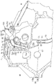
同エンジンのクランクケースを示す縦断面図である。
同クランクケースの上部を後方斜め上方から見た斜視図である。
同クランクケースの上部の縦断面図である。
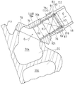
同ブリーザ装置のセパレータの収納部分を示す断面図である。
同セパレータを示す斜視図である。
同エンジンの導入パイプの製造工程を示すフロー図である。
本発明の第2実施形態に係るブリーザ装置のセパレータの収納部分を示す断面図である。
本発明の第3実施形態に係るブリーザ装置のセパレータの収納部分を示す断面図である。
以下、本発明の好ましい実施形態について図面を参照しながら説明する。この明細書中の左右方向は、自動二輪車に乗車したライダーから見た左右を言う。
図1は本発明の第1実施形態に係るブリーザ装置を備えたエンジンを搭載した自動二輪車の側面図である。この自動二輪車の車体フレームFRは、前半部を形成するメインフレーム1と、後半部を形成するシートレール2とを有している。シートレール2は、メインフレーム1の後部に取り付けられている。メインフレーム1の前端にヘッドパイプ4が設けられ、このヘッドパイプ4にステアリングシャフト(図示せず)を介してフロントフォーク8が回動自在に軸支されている。フロントフォーク8の下端部に前輪10が取り付けられ、フロントフォーク8の上端部に操向用のハンドル6が固定されている。
一方、車体フレームFRの中央下部であるメインフレーム1の後端部に、スイングアームブラケット9が設けられている。このスイングアームブラケット9に取り付けたピボット軸16の回りに、スイングアーム12が上下揺動自在に軸支されている。このスイングアーム12の後端部に、後輪14が回転自在に支持されている。車体フレームFRの中央下部でスイングアームブラケット9の前側に、エンジンEが取り付けられている。エンジンEがドライブチェーン11を介して後輪14を駆動する。エンジンEは、4気筒4サイクルの並列多気筒水冷エンジンである。ただし、エンジンEの気筒数、形式等はこれに限定されるものではない。
エンジンEは、左右方向(車幅方向)に延びる軸心を有する回転軸であるクランクシャフト26と、クランクシャフト26を支持するクランクケース28と、その下方に連結されたオイルパン29と、クランクケース28の上面から上方に突出したシリンダブロック30と、その上方のシリンダヘッド32とを有している。これらクランクケース28、シリンダブロック30およびシリンダヘッド32によりエンジン本体EBが構成されている。
クランクケース28は上下2つ割り構造で、上側のクランクケースアッパ28aと下側のクランクケースロワ28bとで構成されている。クランクケース28には、クランクシャフト26が配置されるクランク室82が形成されている。クランク室82は、クランクシャフト26の後方の変速ギヤ列を収納するギヤ室を含んでいる。
シリンダヘッド32の前面の4つの排気ポートに、4本の排気管36が接続されている。これら4本の排気管36が、エンジンEの下方の集合排気管37で集合され、後輪14の右側に配置された排気マフラー38に接続されている。メインフレーム1の上部に燃料タンク15が配置され、シートレール2に操縦者用シート18および同乗車用シート20が支持されている。また、車体前部に、樹脂製のカウリング22が装着されている。
車体フレームFRの左側に、吸気ダクト50が配置されている。吸気ダクト50は、前端開口50aをカウリング22の空気取入口24に臨ませた配置でヘッドパイプ4に支持されている。吸気ダクト50の前端開口50aから導入された空気は、吸気ダクト50内を流動する際にラム効果により昇圧される。
シリンダブロック30の後方でクランクケース28の後部の上面に、外気を浄化するエアクリーナ40および過給機42が、エアクリーナ40を外側にして車幅方向に並んで配置されている。吸気ダクト50は、エンジンEの前方からシリンダブロック30およびシリンダヘッド32の左外側方を通過して、エアクリーナ40に走行風を吸気として導いている。過給機42は、エンジンの動力により駆動され、エアクリーナ40からの清浄空気を加圧してエンジンEに供給する。
過給機42とエンジンEの吸気ポート44との間に、吸気チャンバ46が配置され、過給機42と吸気チャンバ46とが直接接続されている。吸気チャンバ46は、過給機42から供給された高圧の吸気を貯留する。吸気チャンバ46と吸気ポート44との間には、スロットルボディ45が配置されている。これら吸気ダクト50、エアクリーナ40、過給機42、吸気チャンバ46およびスロットルボディ45によりエンジンEの吸気通路IPが構成されている。
図2に示すように、クランクケースアッパ28aの内部の後部に、ブリーザ室55が形成されている。ブリーザ室55にエンジンE内部のオイルミストMが導入されて、ブリーザ室55内でオイルミストMの気液分離が行われる。ブリーザ室55は、シリンダの後側に設けられ、上下方向に縦長に形成されている。詳細には、ブリーザ室55は、クランクケースアッパ28aの上端部近傍から下端部まで延びている。ただし、ブリーザ室55は、クランクケースロア28bまでは達していない。したがって、ブリーザ室55をシールするためのシール部材を省略できる。
ブリーザ室55は、迷路構造(ラビリンス構造)を有している。詳細には、ブリーザ室55は、細分化された部屋が上下に複数並んでおり、各部屋を連通する通路は狭く形成されている。本実施形態のブリーザ室55は、最上部の部屋55a、最下部の部屋55bおよび中間の部屋55cの3つの部屋を有している。
ブリーザ室55の上部に上部開口66が形成され、ブリーザ室55の下部に下部開口68が形成されている。下部開口68は、ブリーザ室55内で気液分離されたオイルミストMの液体成分を排出するためのもので、クランクケースアッパ28aの下端面67に開口している。下部開口68に接続パイプ51が嵌合して取り付けられており、この接続パイプ51にオイル戻しパイプ52が接続されている。オイル戻しパイプ52を介して、ブリーザ室55で気液分離された液体成分がオイルパン29(図1)に戻される。
上部開口66の上方を覆うように、図3に示す上部カバー70がクランクケースアッパ28aに取り付けられている。上部カバー70は、複数のボルト71によりクランクケース28に取り付けられる。上部カバー70に、左右方向に並んで2つの第1および第2貫通孔72,74が形成されている。第1および第2貫通孔72,74は、ブリーザ室55と外部とを連通させる。
左側の第1貫通孔72にブローバイ取出しパイプ76が装着され、ブローバイ取出しパイプ76に、ブローバイガス通路58を形成する図1の導出パイプ60が連結される。導出パイプ60は、エンジンEの吸気通路IPにおける過給機42の上流側、本実施形態では、エアクリーナ40に接続されている。導出パイプ60を介して、ブリーザ室55(図2)で気液分離されたガス成分であるブローバイガスGが吸気通路IPに戻される。本実施形態では、ブローバイ取出しパイプ76は金属製のパイプからなり、導出パイプ60はゴムのような弾性部材からなるホースである。ブローバイ取出しパイプ76の詳細は後述する。
図3の右側の第2貫通孔74にブリーザパイプ75が装着されている。図2に示すように、ブリーザパイプ75は、ほぼ上下方向に延び、ブリーザパイプ75の出口(下端)75aは、ブリーザ室55における上部開口66から下方に離れた位置に配置されている。具体的には、ブリーザパイプ75は、最上部の部屋55aを通過して、中間の部屋55cに開口している。
ブリーザパイプ75の上端部75bは、上部カバー70に設けた突出パイプ部77の根元部分の内側に嵌合されている。突出パイプ部77の上端部分に、ブリーザホース78の一端部78aが接続されている。ブリーザホース78の他端部78bは、図3の導入パイプ84に接続されている。ブリーザホース78はゴムのような弾性部材からなり、ブリーザパイプ75および導入パイプ84は金属製のパイプである。導入パイプ84は、クランク室82の上部に形成された導入口86に接続されている。突出パイプ部77および導入パイプ84とブリーザホース78とは、バンドのような取付具80により接続されている。
図4に示すように、導入パイプ84は、第1先端部84aと第2先端部84bとを有するL字形に形成されている。第1先端部84aはエンジン本体EBの導入口86に圧入され、第2先端部84bがブリーザホース78の他端部78bに連結されている。導入パイプ84のL字形の基部84cにおける第1先端部84aと圧入方向Dの反対側の外径面に、内側からのプレス加工により、圧入方向Dと直交する平坦面85が形成されている。
詳細には、図7の(a)に示すように、鉄パイプのようなパイプ部材130にV字形状の切り込み132を入れ、切込み部分を取り除く。つづいて、(b)に示すように、切り込み132に沿ってパイプ部材130を折り曲げ、接触部134を溶接により固着し、L字形状とする。つぎに、(c)に示すように、導入パイプ84の基部84cの外径面に、金型136を当接させ、第1先端部84aから挿入したピン138で基部84cの内径面を矢印Pの方向に押圧することで、平坦面85を形成する。(d)に示すように、平坦面85に圧入方向Dに圧入力を付加することで、導入パイプ84がエンジン本体EBの導入口86に圧入される。
図3に示す導入口86は、シリンダ軸心から後方に離間した位置で、クランクケース28の上端部に形成される。詳細には、図4に示すように、クランク室82の上部にクランク室開口90が形成され、クランク室開口90がクランク室カバー88により閉塞されている。クランク室カバー88は、クランクケース28の上面に、複数のボルト92(図3)を用いて取り付けられている。
導入パイプ84は、クランクケース28の上端部から上方へ突出して配置され、エンジンの外側を通るブリーザホース78に接続される。図2に示す導入パイプ84、ブリーザホース78およびブリーザパイプ75が、クランク室82からブリーザ室55にオイルミストMを導くブリーザ通路95を構成する。本実施形態では、3つの部材84、78、75でブリーザ通路95を構成しているが、単一の部材で構成してもよい。また、ブリーザ室55とブリーザ通路95とブローバイガス通路58とによりエンジンEのブリーザ装置100が構成される。
ブリーザ通路95は全体として上方に凸となるU字形状に形成されている。具体的には、オイルミストMの流れに沿って、導入パイプ84が上方に延び、ブリーザホース78が左右方向に延び、ブリーザパイプ75が下方に延びている。これにより、ブリーザ通路95内でも気液分離効果を得ることができる。
このようにクランクケース28の外部にブリーザ通路95を設けることで、クランクケース28の内部に通路を形成する場合に比べてブリーザ通路95を長くすることができるうえに、外気によりブリーザ通路95内を流れるガスを冷却することができる。その結果、ブリーザ通路95内での気液分離効果が向上する。また、ブリーザ室55は、クランクケース28の吸気側(後側)で、クランクケースアッパ28aのウォータージャケット94に隣接して形成されている。これにより、ブリーザ室55内の温度上昇が抑制されるので、ブリーザ室55内での気液分離効果が向上する。
図3に示すブローバイ取出しパイプ76に、オイルミストMの気液分離を促進させるセパレータ69が装着されている。図6に示すように、セパレータ69は、金属繊維をからませて形成される円柱体であり、本実施形態では、湾曲した1本のワイヤを集合させて絡ませて構成されている。湾曲した複数のワイヤを集合させて絡ませて構成してもよい。金属繊維(ワイヤ)に代えて、樹脂繊維、樹脂多孔質材料、セラミック樹脂多孔質材料等を用いてもよい。
セパレータ69は、通気性を有する遮蔽構造を備える。具体的には、セパレータ69を通過するオイルミストMの流速を弱めるために通路を遮蔽する構造を有する。セパレータ69は、パイプ径に比べて十分小さな通気通路が形成されたフィルタ構造を有している。セパレータ69は、オイルミストMの気体成分を通過させ、液体成分を液滴化して付着させる構造を備えていればよく、セパレータ69の通気通路は、直線状であっても、非直線状であってもよく、通知通路の断面積は、オイルミスト粒子の外形よりも大きくても小さくてもよい。
本実施形態のセパレータ69は、図5のブローバイガス通路58に挿入されているが、セパレータ69は、ブリーザ通路95からブローバイガス通路58までの間に形成される筒状通路105に収容されていればよい。筒状通路105は、エンジン本体EBに接続されたパイプ体によって形成されており、本実施形態では、ブローバイ取出しパイプ76がこのパイプ体を構成している。
ブローバイ取出しパイプ76の基端部76aは、上部カバー70の第1貫通孔72に圧入嵌合され、締り嵌めとなるように、外径が第1貫通孔72の内径よりも若干大きく形成されている。さらに、ブローバイ取出しパイプ76は、基端部76aから段差部76bを介して拡径される本体部76cを有し、この段差部76bによりブローバイ取出しパイプ76の圧入位置が規定され、本体部76cが第1貫通孔72から内側に入るのが阻止されている。
ブローバイ取出しパイプ76は、セパレータ69が挿入される挿入口112と、セパレータ69が収容される収容部分114とを有している。つまり、セパレータ69は、先端側の挿入口112から挿入され、本体部76cに形成された収容部分114に収容される。これら挿入口112と収容部分114との間に、セパレータ69が挿入口112から抜けるのを防ぐ抜け止め片116が設けられている。本実施形態では、抜け止め片116は、環状のサークリップで構成されている。
抜け止め片116は、凹部87に嵌まり込んだ状態で、抜け止め片116の内径が、セパレータ69の外径よりも小さく設定されている。これにより、セパレータ69が、抜け止め片116を超えてブローバイガス通路58側に移動することが規制される。本実施形態では、抜け止め片116は環状に形成され、周方向の全周に渡って抜け止め片116の内径部がセパレータ69の外形よりも径方向内側に配置されているが、その一部分がセパレータ69の外形よりも径方向内側に突出していればよい。
本実施形態のように、抜け止め片116をブローバイ取出しパイプ76に対して着脱自在に設ければ、抜け止め片116を取り外すことで、セパレータ69の着脱も可能となる。これにより、セパレータ69の洗浄、交換が可能となるから、利便性が向上する。
ブローバイ取出しパイプ76は、さらに、内径が縮径する縮径部分118を有し、この縮径部分118と挿入口112との間に、収容部分114が位置している。本実施形態では、前記基端部76aが縮径部分118を構成している。セパレータ69の外径X1は、縮径部分118の内径X2よりも大きく、且つ収容部分(本体部)114の内径X3よりも小さく設定されている(X2<X1<X3)。これにより、セパレータ69がエンジン本体EB側へ移動するのが規制されている。このように、セパレータ69は、抜け止め片116と縮径部分118とにより軸方向の移動が規制されている。
ブローバイ取出しパイプ76の先端に、弾性ホースからなる前記導出パイプ60が接続されている。ブローバイ取出しパイプ76と導出パイプ60は、バンドのような取付具81により接続されている。ブローバイ取出しパイプ76の本体部76cに、径方向外方に突出する突出部83が形成され、導出パイプ60がブローバイ取出しパイプ76から外れるのを防いでいる。この突出部83よりもエンジン本体EB側で、取付具81によりブローバイ取出しパイプ76と導出パイプ60とがクランプされている。これにより、取付具81の軸方向への移動が規制されている。
ブローバイ取出しパイプ76の内面における突出部83に対応する部分は、径方向外側に凹んだ凹部87が形成されており、この凹部87に前記抜け止め片116が嵌め込まれている。これにより、抜け止め片116の軸方向への移動が規制されている。本実施形態では、導出パイプ60の抜け止め用に設けた突出部83を利用して、抜け止め片116を嵌め込むための凹部87を形成している。このように、1つの工程で、突出部83と凹部87とが形成されるから、製造作業が容易化される。
セパレータ69の軸方向寸法は、突出部83から段差部76bまでの長さ以下に設定すれば、ブローバイ取出しパイプ76内に容易に配置できるので好ましい。特に、セパレータ69の軸方向寸法を突出部83から段差部76bまでの長さと同じとすれば、セパレータ69を大形化して液体成分の捕捉効果を高めつつ、セパレータ69の軸方の移動も規制できるから、より好ましい。
ブローバイ取出しパイプ76は、後方に向かって上方に傾斜して延びており、セパレータ69の下方にブリーザ室55が配置されている。したがって、セパレータ69に付着したオイルミストMの液体成分は、自重で流下してブリーザ室55に回収される。
つぎに、本実施形態のエンジンEのブローバイガスGおよびオイルの流れを説明する。図1のエンジンEが始動すると、ピストンとシリンダの間隙から混合気が漏出しクランク室82内にブローバイガスが漏れ出す。一方、クランク室82の下方のオイルパン29内には、このオイルパン29から供給され、エンジンEの各部位を潤滑、冷却した後のオイルが戻されている。
図4に示すように、ブローバイガスGを含んだオイルミストMが、クランク室82の上部の導入パイプ84の内部(ブリーザ通路95)に導かれる。導入パイプ84に導かれたオイルミストMは、図2に示すブリーザホース78およびブリーザパイプ75を通って、ブリーザ室55に導入される。
ブリーザ室55に導入されたオイルミストMは、ブリーザ室55内で気液分離される。オイルミストMの気体成分であるブローバイガスGは、ブリーザ室55の上方に移動し、図5のブローバイ取出しパイプ76に連結された導出パイプ58を介して、エンジンEの吸気通路IP(図1)に戻される。
ブローバイガスGが、ブローバイガス通路58を通過する際、気体成分はセパレータ69を通過し、液体成分はセパレータ69により液滴化されてセパレータ69に付着する。液滴化された液体成分は、ブローバイ取出しパイプ76から下方のブリーザ室55に回収される。このセパレータ69で液滴化された液体成分であるオイルOLと、図2のブリーザ室55内で気液分離されたオイルミストMの液体成分であるオイルOLは、オイル戻しパイプ52を通って、図1のオイルパン29に戻される。このように、ブリーザ室55での気液分離に加えて、セパレータ69でも気液分離が行われるので、ブリーザ装置55の気液分離効果が向上する。
セパレータ69が、ブリーザ室55の下流側、すなわち、ブリーザ室55で気液分離された後のブローバイガスGが通過するブローバイガス通路58に配置されている。したがって、ブリーザ室55で気液分離された液体成分が、クランク室82の圧力脈動によって、ブローバイガス通路58に向かって飛び出たとしても、セパレータ69により捕捉される。これにより、液体成分が、セパレータ69を超えてブローバイガス通路58に流入するのを防ぐことができる。また、セパレータ69により通路抵抗が大きくなるので、セパレータ69の下流側から上流側にブローバイガスGが逆流するのを抑制できる。
図5に示すように、セパレータ69は、エンジン本体EBに接続されたブローバイ取出しパイプ76に配置されている。これにより、ブローバイ取出しパイプ76にセパレータ69を収容した状態で、エンジン本体EBにブローバイ取出しパイプ76を接続することができる。このように、ブローバイ取出しパイプ76とセパレータ69とをサブユニット化することで、セパレータ69のエンジン本体EBへの取り付けが容易になる。
ブローバイ取出しパイプ76の挿入口112と収容部分114との間に、抜け止め片116が設けられている。これにより、ブローバイガスGの通過や、セパレータ69の前後の圧力差により、セパレータ69が移動するのを防止できる。
また、ブローバイ取出しパイプ76の挿入口112と縮径部分118との間に、収容部分が位置し、抜け止め片116と縮径部分118との間にセパレータ69が配置されている。これにより、挿入口112からブローバイ取出しパイプ76に挿入されたセパレータ69がブローバイ取出しパイプ76の軸方向に移動するのを防ぐことができる。
さらに、金属パイプ部分であるブローバイ取出しパイプ76にセパレータ69が配置されているので、ブローバイ取出しパイプ76に形成された凹部87内に抜け止め片116が嵌め込まれている。凹部87は、弾性パイプ部分である導出パイプ60が外れるのを防ぐための突出部83と同時に形成される。このように、導出パイプ60の外れ防止用の突出部83を利用して容易に抜け止め片116を設けることができる。
また、導出パイプ(弾性パイプ部分)60にセパレータ69を収容すると、導出パイプ60とセパレータ69とが接触して、導出パイプ60が劣化することが懸念されるが、ブローバイ取出しパイプ(金属パイプ部分)76にセパレータ69を設けることで、導出パイプ60の劣化を抑制できる。ただし、セパレータ69との接触に起因する導出パイプ60の劣化を抑制できる場合、弾性パイプ部分である導出パイプ60にセパレータ69を収容することもできる。
ブローバイ取出しパイプ76がブリーザ室55から後方に向かって上方に傾斜して延びているので、セパレータ69により分離した液体成分が自重でブリーザ室55内に落下する。
図6に示すように、セパレータ69は、金属繊維をからませて形成される円柱体であるので、樹脂製に比べて、耐久性が高い。また、セパレータ69は、1本のワイヤを集合させて絡ませて構成されているので、一部が解けてもワイヤが抜け落ちることがない。
図3に示すように、導入パイプ84の基部84cにおける第1先端部84aと圧入方向Dの反対側の外径面が、圧入方向Dと垂直な平坦面85にプレス成形されている。これにより、平坦面85を押し付けて導入パイプ84をエンジン本体EBに圧入することができるから、導入パイプ84のエンジン本体EBへの取り付けが容易である。また、平坦面85はプレス加工で成形されているので、導入パイプ84の構造も簡単である。
図8は、本発明の第2実施形態に係るブリーザ装置100におけるセパレータ69の収納構造を示す。第2実施形態では、セパレータ69は、ブリーザ通路95における導入パイプ84の内側に配置されている。つまり、導入パイプ84が、筒状通路105を形成するパイプ体を構成する。換言すれば、セパレータ69は、ブリーザ通路95における弾性パイプ部分(ブリーザホース78)ではなく、金属パイプ部分(導入パイプ84)に配置されている。この第2実施形態においても、弾性パイプ部分であるブリーザホース78にセパレータ69を設けてもよい。
詳細には、セパレータ69は、導入パイプ84の第2先端部84bに配置されている。つまり、第2先端部84bの開口が、セパレータ69を挿入する挿入口112を構成する。さらに、導入パイプ84も、第1実施形態と同様の抜け止め片116を備えている。第2先端部84bに接続されるブリーザホース78は、ブリーザ室55に向かって下方に傾斜している。したがって、セパレータ69で液滴化されたオイルミストMの液体成分は、ブリーザ室55に回収される。セパレータ69の配置以外の構成は、第1実施形態と同じである。したがって、第2実施形態も第1実施形態と同様の効果を奏する。
図9は、本発明の第3実施形態に係るブリーザ装置100におけるセパレータ69の収納構造を示す。第3実施形態では、ブリーザ室55の上部開口66に、上方に突出するホース接続部120が装着され、このホース接続部120にブリーザホース78が接続されている。また、上部開口66から下方に突出するパイプ接続部122に、ブリーザパイプ75が接続されている。ホース接続部120およびパイプ接続部122は金属パイプからなり、ブリーザパイプ75はゴムのような弾性部材からなる。第3実施形態のセパレータ69は、ブリーザ通路95におけるホース接続部122の内側に配置されている。つまり、ホース接続部122が、筒状通路105を形成するパイプ体を構成する。
第2実施形態と同様に、セパレータ69は、ブリーザ通路95における弾性パイプ部分(ブリーザホース78)ではなく、金属パイプ部分(パイプ接続部122)に配置されている。詳細には、セパレータ69は、パイプ接続部122の下端部122aに配置されている。つまり、下端部122aの開口が、セパレータ69を挿入する挿入口112を構成する。さらに、図示はしていないが、パイプ接続部122にも、第1実施形態と同様の抜け止め片116が設けられている。セパレータ69で液滴化されたオイルミストMの液体成分は、パイプ接続部122からブリーザパイプ75を通って落下し、ブリーザ室55に回収される。この第3実施形態においても、弾性パイプ部分であるブリーザパイプ75にセパレータ69を設けてもよい。
セパレータ69の配置以外の構成は、第1および第2実施形態と同じである。したがって、第3実施形態も第1および第2実施形態と同様の効果を奏する。また、第3実施形態では、セパレータ69をパイプ接続部122に配置しているが、図9に二点鎖線で示すように、セパレータ69を、ブリーザ通路95におけるホース接続部120の上端部120a、あるいはブリーザパイプ75の下端部(出口)75aの内側に配置してもよい。この場合、ホース接続部120またはブリーザパイプ75が、筒状通路105を形成するパイプ体を構成する。この場合も、セパレータ69で液滴化されたオイルミストMの液体成分は、ブリーザパイプ75を通って落下し、ブリーザ室55に回収される。
第2および第3実施形態においても、パイプ体におけるセパレータ69を挟んで、抜け止め片116と反対側に、縮径部分を設けてもよい。縮径部分は、例えば、図9に二点鎖線で示すような、パイプ体の内周面から径方向内方に突出する突起部118Aで構成してもよい。突起部118Aは周方向の全周に渡って形成されてもよく、また、周方向に離間して複数設けられてもよい。
また、第2および第3実施形態では、ブリーザ室55の上流側のブリーザ通路95にセパレータ69が配置されている。したがって、ブリーザ通路95内のオイルミストMの通過速度(圧力変動)がセパレータ69により抑制され、ブリーザ室55内の圧力変動を抑制できる。これにより、ブリーザ室55で気液分離された液体成分が、下流側のブローバイガス通路58内に吹き飛ばされることを防ぐことができる。
本発明のブリーザ装置100は、過給エンジンに好適に用いられる。このようなエンジンは、クランク室の圧力が高く、気液分離の要求が高い。また、上記各実施形態では、セパレータ69は、ブリーザ通路95からブローバイガス通路58まで間に1つ設けられていたが、2つ以上の個所に設けてもよい。具体的には、例えば、ブローバイガス通路58に第1実施形態のセパレータ69(図5)を設けたうえで、ブリーザ通路95に第2実施形態のセパレータ69(図8)を設けてもよい。これにより、オイルミストMの気液分離効果がさらに向上する。複数個所にセパレータ69を設ける場合、セパレータ69の通気通路の通路面積を異ならせてもよい。この場合、例えば、下流側に配置されるセパレータ69の通気通路の通路面積を、上流側の通路面積よりも小さくするのがよい。
セパレータ69が挿入されるパイプ体は、その軸心が、搭載状態で、上下方向を向くか、あるいは上下方向に傾斜していることが好ましい。この場合、搭載状態において、ブリーザ室55側の端部が下方に位置するのが好ましい。これにより、セパレータ69に捕捉された液体成分が自重でブリーザ室55に流下するので、セパレータ69に捕捉された液体成分が逆流するのを防ぐことができる。
上記第1~第3実施形態では、エンジン本体EBに着脱自在に取り付けられるパイプ体にセパレータ69を収容したが、エンジン本体EB内に筒状通路を形成し、その筒状通路内にセパレータ69を配置してもよい。また、筒状通路105は、横断面形状が円形のほか、楕円形、三角形以上の多角形でもよい。
本発明は、以上の実施形態に限定されるものでなく、本発明の要旨を逸脱しない範囲内で、種々の追加、変更または削除が可能である。例えば、上記実施形態では、自動二輪車のエンジンに適用した例を説明したが、本発明のブリーザ装置100は、自動二輪車以外の車両、船舶等のエンジンにも適用可能で、さらに、地上設置のエンジンにも適用できる。また、本発明のブリーザ装置100は、過給エンジン以外にも適用できる。したがって、そのようなものも本発明の範囲内に含まれる。
26 クランクシャフト
55 ブリーザ室
58 ブローバイガス通路
60 導出パイプ(弾性パイプ部分)
69 セパレータ(円柱体)
82 クランク室
95 ブリーザ通路
100 ブリーザ装置
75 ブリーザパイプ(パイプ体)
76 ブローバイ取出しパイプ(パイプ体、金属パイプ部分)
78 ブリーザホース(弾性パイプ部分)
84 導入パイプ(パイプ体、金属パイプ部分)
85 平坦面
105 筒状通路
112 挿入口
114 収容部分
116 抜け止め片(サークリップ)
118 縮径部分
120 ホース接続部(パイプ体)
122 パイプ接続部(パイプ体、金属パイプ部分)
E エンジン
EB エンジン本体
G ブローバイガス
IP 吸気通路
M オイルミスト
55 ブリーザ室
58 ブローバイガス通路
60 導出パイプ(弾性パイプ部分)
69 セパレータ(円柱体)
82 クランク室
95 ブリーザ通路
100 ブリーザ装置
75 ブリーザパイプ(パイプ体)
76 ブローバイ取出しパイプ(パイプ体、金属パイプ部分)
78 ブリーザホース(弾性パイプ部分)
84 導入パイプ(パイプ体、金属パイプ部分)
85 平坦面
105 筒状通路
112 挿入口
114 収容部分
116 抜け止め片(サークリップ)
118 縮径部分
120 ホース接続部(パイプ体)
122 パイプ接続部(パイプ体、金属パイプ部分)
E エンジン
EB エンジン本体
G ブローバイガス
IP 吸気通路
M オイルミスト
Claims (8)
- エンジン内のオイルミストが導入されて気液分離を行うラビリンス構造が形成されたブリーザ室と、
クランクシャフトが配置されるクランク室から前記ブリーザ室にオイルミストを導くブリーザ通路と、
前記ブリーザ室で気液分離されたブローバイガスを吸気通路に導くブローバイガス通路と、
前記ブリーザ通路から前記ブローバイガス通路までの間に形成される筒状通路に収容されて通気性を有する遮蔽構造となるセパレータと、
を備えたエンジンのブリーザ装置。 - 請求項1に記載のブリーザ装置において、前記筒状通路は、エンジン本体に接続されたパイプ体によって形成されているエンジンのブリーザ装置。
- 請求項1または2に記載のブリーザ装置において、前記筒状通路は、前記セパレータが挿入される挿入口と、前記セパレータが収容される収容部分とを有し、
前記挿入口と前記収容部分との間に、前記セパレータが前記挿入口から抜けるのを防ぐ抜け止め片が設けられているエンジンのブリーザ装置。 - 請求項3に記載のブリーザ装置において、前記筒状通路は、さらに、内径が縮径する縮径部分を有し、
前記挿入口と前記縮径部分との間に、前記収容部分が位置しているエンジンのブリーザ装置。 - 請求項1から4のいずれか一項に記載のブリーザ装置において、前記ブリーザ通路または前記ブローバイガス通路は、弾性を有する弾性パイプ部分と、前記弾性パイプ部分が連結される金属パイプ部分とを有し、
前記セパレータが金属パイプ部分に収容されているエンジンのブリーザ装置。 - 請求項1から5のいずれか一項に記載のブリーザ装置において、前記筒状通路が上下方向に沿って延び、
前記セパレータの下方に前記クランク室または前記ブリーザ室が配置されているエンジンのブリーザ装置。 - 請求項1から6のいずれか一項に記載のブリーザ装置において、前記セパレータは、金属繊維をからませて形成される円柱体であるエンジンのブリーザ装置。
- 請求項1から7のいずれか一項に記載のブリーザ装置において、前記ブリーザ通路または前記ブローバイガス通路は、弾性を有する弾性パイプ部分と、金属材料からなる金属パイプ部分とを有し、
前記金属パイプ部分は、エンジン本体に圧入される第1先端部と、前記弾性パイプ部分に連結される第2先端部とを有するL字形に形成され、
前記金属パイプ部分のL字形の基部における前記第1先端部と圧入方向の反対側の外形面が、前記圧入方向と垂直な平坦面にプレス成形されているエンジンのブリーザ装置。
Priority Applications (2)
| Application Number | Priority Date | Filing Date | Title |
|---|---|---|---|
| JP2016537714A JP6246934B2 (ja) | 2014-07-29 | 2014-12-22 | エンジンのブリーザ装置 |
| US15/412,944 US9822679B2 (en) | 2014-07-29 | 2017-01-23 | Breather device for engine |
Applications Claiming Priority (4)
| Application Number | Priority Date | Filing Date | Title |
|---|---|---|---|
| JP2014-153656 | 2014-07-29 | ||
| JP2014153657 | 2014-07-29 | ||
| JP2014-153657 | 2014-07-29 | ||
| JP2014153656 | 2014-07-29 |
Related Child Applications (1)
| Application Number | Title | Priority Date | Filing Date |
|---|---|---|---|
| US15/412,944 Continuation US9822679B2 (en) | 2014-07-29 | 2017-01-23 | Breather device for engine |
Publications (1)
| Publication Number | Publication Date |
|---|---|
| WO2016017044A1 true WO2016017044A1 (ja) | 2016-02-04 |
Family
ID=55179537
Family Applications (1)
| Application Number | Title | Priority Date | Filing Date |
|---|---|---|---|
| PCT/JP2014/083916 Ceased WO2016017044A1 (ja) | 2014-07-29 | 2014-12-22 | エンジンのブリーザ装置 |
Country Status (3)
| Country | Link |
|---|---|
| US (2) | US10107161B2 (ja) |
| JP (1) | JP6246934B2 (ja) |
| WO (1) | WO2016017044A1 (ja) |
Cited By (1)
| Publication number | Priority date | Publication date | Assignee | Title |
|---|---|---|---|---|
| JP2022143952A (ja) * | 2021-03-18 | 2022-10-03 | ヤンマーホールディングス株式会社 | エンジン |
Families Citing this family (2)
| Publication number | Priority date | Publication date | Assignee | Title |
|---|---|---|---|---|
| JP2878295B2 (ja) | 1989-02-10 | 1999-04-05 | タバイエスペック株式会社 | 液体クリーニング装置 |
| JP6842342B2 (ja) * | 2017-03-30 | 2021-03-17 | 本田技研工業株式会社 | 内燃機関の駆動部構造 |
Citations (3)
| Publication number | Priority date | Publication date | Assignee | Title |
|---|---|---|---|---|
| JPS5759913U (ja) * | 1980-09-26 | 1982-04-09 | ||
| JPS6337452Y2 (ja) * | 1983-06-30 | 1988-10-04 | ||
| JPH0342012U (ja) * | 1989-08-30 | 1991-04-22 |
Family Cites Families (16)
| Publication number | Priority date | Publication date | Assignee | Title |
|---|---|---|---|---|
| US3081942A (en) | 1961-09-18 | 1963-03-19 | Ibm | Digital-to-analog control system |
| JPS5759913A (en) | 1980-09-29 | 1982-04-10 | Sumitomo Chem Co Ltd | Preparation of highly stereoregular alpha-olefinic polymer |
| JPS59100910U (ja) * | 1982-12-24 | 1984-07-07 | 本田技研工業株式会社 | V型内燃機関用ブロ−バイガス還元装置 |
| JPH0618025Y2 (ja) * | 1985-05-03 | 1994-05-11 | 三菱重工業株式会社 | 側弁式汎用エンジンのブリーザ装置 |
| JPH0342012A (ja) | 1989-07-07 | 1991-02-22 | Nippon Steel Corp | 有機性廃棄物の発酵排ガス脱臭方法 |
| EP0640002B1 (en) * | 1991-09-03 | 1996-07-17 | RAGUSA, Guiseppe | Air filter |
| JPH05179925A (ja) * | 1991-12-26 | 1993-07-20 | Suzuki Motor Corp | 汎用エンジンのブリーザ装置 |
| JP4119023B2 (ja) * | 1998-11-25 | 2008-07-16 | 本田技研工業株式会社 | エンジンにおけるブリーザ装置 |
| JP3943306B2 (ja) * | 2000-01-19 | 2007-07-11 | 本田技研工業株式会社 | エンジンのブリーザー装置 |
| US6354249B1 (en) * | 2000-06-13 | 2002-03-12 | Kohler Co. | Engine with coolant pump |
| JP4563824B2 (ja) * | 2005-01-18 | 2010-10-13 | 本田技研工業株式会社 | 自動二輪車用エンジン |
| JP4704162B2 (ja) | 2005-09-13 | 2011-06-15 | 川崎重工業株式会社 | エンジンのブリーザ構造 |
| JP2007077925A (ja) | 2005-09-15 | 2007-03-29 | Kawasaki Heavy Ind Ltd | 車輌用エンジン |
| US8047186B2 (en) * | 2008-11-24 | 2011-11-01 | Toyota Motor Engineering & Manufacturing North America, Inc. | Oil separator |
| US20100319665A1 (en) * | 2009-06-18 | 2010-12-23 | Aeon Motor Co., Ltd. | Fuel-air separation structure improvement for engine blow-by of vehicles |
| US9624821B2 (en) * | 2011-05-19 | 2017-04-18 | Toyota Jidosha Kabushiki Kaisha | Air intake structure for internal combustion engine |
-
2014
- 2014-12-22 JP JP2016537714A patent/JP6246934B2/ja active Active
- 2014-12-22 WO PCT/JP2014/083916 patent/WO2016017044A1/ja not_active Ceased
-
2015
- 2015-06-29 US US14/754,428 patent/US10107161B2/en active Active
-
2017
- 2017-01-23 US US15/412,944 patent/US9822679B2/en active Active
Patent Citations (3)
| Publication number | Priority date | Publication date | Assignee | Title |
|---|---|---|---|---|
| JPS5759913U (ja) * | 1980-09-26 | 1982-04-09 | ||
| JPS6337452Y2 (ja) * | 1983-06-30 | 1988-10-04 | ||
| JPH0342012U (ja) * | 1989-08-30 | 1991-04-22 |
Cited By (2)
| Publication number | Priority date | Publication date | Assignee | Title |
|---|---|---|---|---|
| JP2022143952A (ja) * | 2021-03-18 | 2022-10-03 | ヤンマーホールディングス株式会社 | エンジン |
| JP7439005B2 (ja) | 2021-03-18 | 2024-02-27 | ヤンマーホールディングス株式会社 | エンジン |
Also Published As
| Publication number | Publication date |
|---|---|
| JP6246934B2 (ja) | 2017-12-13 |
| JPWO2016017044A1 (ja) | 2017-04-27 |
| US9822679B2 (en) | 2017-11-21 |
| US20170130624A1 (en) | 2017-05-11 |
| US20160032797A1 (en) | 2016-02-04 |
| US10107161B2 (en) | 2018-10-23 |
Similar Documents
| Publication | Publication Date | Title |
|---|---|---|
| JP6228131B2 (ja) | エンジンの過給システム | |
| JP6444351B2 (ja) | 車載内燃機関のオイルフィルター取付け構造 | |
| JP6262854B2 (ja) | 自動二輪車の吸気ダクト | |
| JP6241743B2 (ja) | 車両用内燃機関のブリーザ装置 | |
| CN101907008B (zh) | 摩托车发动机的通气装置 | |
| JP7314525B2 (ja) | 自動二輪車 | |
| JP6246934B2 (ja) | エンジンのブリーザ装置 | |
| JP2015113733A (ja) | 鞍乗り型車両の吸気装置 | |
| JP6693793B2 (ja) | エアクリーナ | |
| JP6459789B2 (ja) | エアクリーナ構造 | |
| JP6492940B2 (ja) | 鞍乗型車両 | |
| JP4257902B2 (ja) | 内燃機関のブローバイガス還元装置 | |
| JP2013194543A (ja) | 鞍乗り型車両における吸気装置 | |
| US8413639B2 (en) | Fuel supplying apparatus for internal combustion engine | |
| JP6680885B2 (ja) | 車載内燃機関の吸気構造 | |
| JP6135488B2 (ja) | エンジンのブリーザ装置 | |
| JP6319012B2 (ja) | エンジンのブリーザ室レイアウト構造 | |
| US10294898B2 (en) | Air intake chamber structure | |
| US9631527B2 (en) | Exhaust system | |
| JP4115007B2 (ja) | 自動二輪車の始動装置 | |
| JP2014015842A (ja) | 鞍乗り型車両用内燃機関のエアクリーナ | |
| JP2014047768A (ja) | シリンダヘッドおよび鞍乗り型車両 | |
| JP2019199867A (ja) | 鞍乗型車両 | |
| JP6475608B2 (ja) | ブリーザ装置付エンジン | |
| JP6291858B2 (ja) | 2次エアークリーナー |
Legal Events
| Date | Code | Title | Description |
|---|---|---|---|
| 121 | Ep: the epo has been informed by wipo that ep was designated in this application |
Ref document number: 14898509 Country of ref document: EP Kind code of ref document: A1 |
|
| ENP | Entry into the national phase |
Ref document number: 2016537714 Country of ref document: JP Kind code of ref document: A |
|
| NENP | Non-entry into the national phase |
Ref country code: DE |
|
| 122 | Ep: pct application non-entry in european phase |
Ref document number: 14898509 Country of ref document: EP Kind code of ref document: A1 |