WO2016013641A1 - 特定物質の解析用モデルの作成方法、特定物質の解析用モデルの作成用コンピュータプログラム、特定物質のシミュレーション方法及び特定物質のシミュレーション用コンピュータプログラム - Google Patents
特定物質の解析用モデルの作成方法、特定物質の解析用モデルの作成用コンピュータプログラム、特定物質のシミュレーション方法及び特定物質のシミュレーション用コンピュータプログラム Download PDFInfo
- Publication number
- WO2016013641A1 WO2016013641A1 PCT/JP2015/071042 JP2015071042W WO2016013641A1 WO 2016013641 A1 WO2016013641 A1 WO 2016013641A1 JP 2015071042 W JP2015071042 W JP 2015071042W WO 2016013641 A1 WO2016013641 A1 WO 2016013641A1
- Authority
- WO
- WIPO (PCT)
- Prior art keywords
- model
- substance
- specific substance
- filler
- creating
- Prior art date
- Legal status (The legal status is an assumption and is not a legal conclusion. Google has not performed a legal analysis and makes no representation as to the accuracy of the status listed.)
- Ceased
Links
Images






Classifications
-
- G—PHYSICS
- G16—INFORMATION AND COMMUNICATION TECHNOLOGY [ICT] SPECIALLY ADAPTED FOR SPECIFIC APPLICATION FIELDS
- G16C—COMPUTATIONAL CHEMISTRY; CHEMOINFORMATICS; COMPUTATIONAL MATERIALS SCIENCE
- G16C60/00—Computational materials science, i.e. ICT specially adapted for investigating the physical or chemical properties of materials or phenomena associated with their design, synthesis, processing, characterisation or utilisation
-
- G—PHYSICS
- G01—MEASURING; TESTING
- G01N—INVESTIGATING OR ANALYSING MATERIALS BY DETERMINING THEIR CHEMICAL OR PHYSICAL PROPERTIES
- G01N33/00—Investigating or analysing materials by specific methods not covered by groups G01N1/00 - G01N31/00
- G01N33/44—Resins; Plastics; Rubber; Leather
-
- G—PHYSICS
- G06—COMPUTING OR CALCULATING; COUNTING
- G06F—ELECTRIC DIGITAL DATA PROCESSING
- G06F30/00—Computer-aided design [CAD]
Definitions
- the present invention relates to a method for creating a model for analyzing a specific substance, a computer program for creating a model for analyzing a specific substance, a simulation method for a specific substance, and a computer program for simulating a specific substance.
- the present invention relates to a method for creating a model for analyzing a specific substance, a computer program for creating a model for analyzing a specific substance, a simulation method for a specific substance, and a computer program for simulating a specific substance.
- the present invention has been made in view of such circumstances, and can efficiently create a model for analyzing a specific substance containing two or more kinds of substances, and accurately analyze the influence of specific substances on the material properties.
- An object of the present invention is to provide a method for creating a model for analyzing a specific substance, a computer program for creating a model for analyzing a specific substance, a simulation method for a specific substance, and a computer program for simulating a specific substance.
- the method for creating a model for analyzing a specific substance of the present invention is a method for creating a model for analyzing a specific substance that creates a model for analyzing a specific substance containing at least two substances by a molecular dynamics method using a computer.
- a first step of setting a model creation area for creating a model for analyzing a specific substance, a second step of creating a model of the first substance in the model creation area, and a second substance in the model creation area A third step of setting an arrangement area of the second substance, and a step of creating a void for arranging the second substance by excluding the model of the first substance in the arrangement area of the second substance from the arrangement area of the second substance 4 steps and a 5th step which arrange
- a model of the first substance is created in the set model creation area, and a second substance model is arranged by providing a gap in the created model of the first substance. Therefore, even when the number of second substances arranged in the model is large, it is possible to efficiently create a model of a specific substance containing two or more kinds of substances. Thereby, it is possible to realize a method for creating a model for analyzing a specific substance that can accurately analyze the influence of the specific substance on the material characteristics.
- the second step it is preferable to create the void in which the second substance is arranged using a coarse-grained molecular dynamics method. Since this method improves the calculation efficiency, it is possible to efficiently create a void.
- the second step it is preferable to designate an arrangement region of the second substance by simulation.
- this method it becomes easy to specify the arrangement position of the second substance in the model creation region, so that the second substance can be arranged efficiently even when a plurality of models of the second substance are used. Become.
- the first substance is preferably a polymer material. This method makes it possible to create a model for analysis of a specific substance containing a polymer material.
- the second substance is preferably a filler. This method makes it possible to create a model for analyzing a specific substance containing a filler.
- the computer program for creating a model for analyzing a specific substance is characterized by causing a computer to execute the method for creating a model for analyzing a specific substance.
- a model of the first substance is created in the set model creation area, and a second substance is arranged by providing a gap in the created model of the first substance. Therefore, it is possible to efficiently create a model of a specific substance containing two or more kinds of substances, and it is possible to create a model for analyzing a specific substance that can accurately analyze the influence of the specific substance on the material characteristics.
- the specific substance simulation method of the present invention includes a molecular dynamics method in which an interaction is set between the model of the first substance and the model of the second substance created by the method for creating the model for analyzing the specific substance.
- the relaxation calculation is performed using
- the method for simulating a specific substance of the present invention is characterized in that a deformation analysis is executed using the analysis model for a specific substance created by the method for creating an analysis model for the specific substance.
- the deformation analysis is executed using the analysis model of the specific substance containing the first substance and the second substance, so that the influence of the shape of the specific substance on the material characteristics is analyzed. It becomes possible to obtain the mechanical characteristics of the compound.
- the computer program for simulation of a specific substance of the present invention is characterized by causing a computer to execute the simulation method of the specific substance.
- This computer program for simulation of a specific substance can efficiently create a model for analyzing a specific substance containing two or more kinds of substances, and can accurately analyze the influence of the specific substance on the material properties.
- a method for creating a model for analyzing a specific substance capable of efficiently creating a model for analyzing a specific substance containing two or more types of substances and accurately analyzing the influence on the material properties of the specific substance,
- a computer program for creating a model for analyzing a specific substance, a simulation method for the specific substance, and a computer program for simulating the specific substance can be realized.
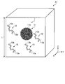
- FIG. 1A is a conceptual diagram showing an example of an analysis model created by the method for creating an analysis model for a specific substance according to the present embodiment.
- FIG. 1B is a conceptual diagram showing another example of an analysis model created by the method for creating an analysis model for a specific substance according to the present embodiment.
- FIG. 1C is a conceptual diagram showing another example of an analysis model created by the method for creating an analysis model for a specific substance according to the present embodiment.
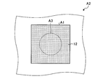
- FIG. 2A is an explanatory diagram of a method for creating an analysis model for a specific substance according to the present embodiment.
- FIG. 2B is an explanatory diagram of a method for creating an analysis model for a specific substance according to the present embodiment.
- FIG. 2C is an explanatory diagram of a method for creating a specific substance analysis model according to the present embodiment.
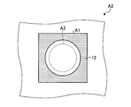
- FIG. 2D is an explanatory diagram of a method for creating an analysis model for a specific substance according to the present embodiment.
- FIG. 2E is an explanatory diagram of a method for creating a model for analyzing a specific substance according to the present embodiment.
- FIG. 3A is an explanatory diagram of the arrangement of the filler model according to the present embodiment.
- FIG. 3B is an explanatory diagram of the arrangement of filler models according to the present embodiment.
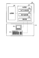
- FIG. 4 is a functional block diagram of an analysis apparatus that executes a method for creating a model for analyzing a specific substance and a simulation method for the specific substance according to the embodiment of the present invention.
- FIG. 5 is a flowchart showing an outline of an example of a method for creating a specific substance analysis model according to the present embodiment.
- the method for creating a model for analyzing a specific substance is to create a model for analyzing a specific substance that creates a model for analyzing a specific substance containing at least two substances by a molecular dynamics method using a computer.
- a method includes a first step of setting a model creation region for creating an analysis model of a specific substance, a second step of creating a model of the first substance in the model creation region, and a second step in the model creation region.
- a fifth step of creating a model for analyzing the specific substance by disposing the second substance in the gap.
- FIG. 1A is a conceptual diagram showing an example of an analysis model 1 created by the method for creating an analysis model for a specific substance according to the present embodiment.
- a model 1 for analyzing a specific substance according to the present embodiment includes a filler model 11 and a polymer model in a model creation region A1 which is a substantially cubic virtual space whose one side is a distance L1. 12 is arranged and a specific substance to be analyzed is modeled.
- the specific substance to be analyzed is a composite material containing a filler (first substance) and a polymer (second substance) that is a polymer material will be described.
- the present invention can be applied to various materials other than composite materials containing two kinds of substances.
- FIG. 1B is a conceptual diagram showing another example of an analysis model created by the method for creating an analysis model for a specific substance according to the present embodiment.
- the first filler model 11A and the second filler model 11B are converted into filler models in the model creation area A1. ing.
- the first filler model 11A and the second filler model 11B are configured by a plurality of filler particles 11a gathering in a substantially spherical shape. Further, the first filler model 11A and the second filler model 11B are agglomerated with each other and a part of the outer edge portion is connected (shared).
- FIG. 1C is a conceptual diagram showing another example of an analysis model created by the method for creating an analysis model for a specific substance according to the present embodiment.
- the analysis model 3 shown in FIG. 1C instead of the filler model of the analysis model 1 shown in FIG. 1, the first filler model 11A, the second filler model 11B, and the third filler model in the model creation region A1.
- 11C and the fourth filler model 11D are modeled.
- the first filler model 11A, the second filler model 11B, the third filler model 11C, and the fourth filler model 11D are configured by a plurality of filler particles 11a that are each assembled into a substantially spherical body.
- the analysis model 2 having a complicated shape in which the two first filler models 11A and the second filler model 11B are aggregated, the four first filler models 11A, the second It is also possible to create the analysis model 3 having a complicated shape in which the filler model 11B, the third filler model 11C, and the fourth filler model 11D are aggregated.
- fillers examples include carbon black, silica, and alumina.
- the filler model 11 is modeled as a substantially spherical body in which a plurality of filler atoms and filler particles 11a as an aggregate of a plurality of filler atoms are aggregated.
- the relative position of the filler particles 11a is specified by a bond chain (not shown) between the plurality of filler particles 11a.
- This binding chain (not shown) has a function as a spring in which an equilibrium length, which is a binding distance between filler particles 11a, and a spring constant are defined, and binds between the filler particles 11a.
- the bond chain is a bond in which the relative position of the filler particle 11a and the potential at which force is generated by twisting, bending, or the like are defined.
- the filler model 11 is numerical data (including the mass, volume, diameter, initial coordinates, and the like of the filler particles 11a) for handling the filler by molecular dynamics. Numerical data of the filler model 11 is input to the computer.
- the polymer examples include rubber, resin, and elastomer.
- the polymer model 12 is formed by connecting a plurality of polymer atoms and polymer particles 12a, which are aggregates of a plurality of polymer atoms, via a bond chain 12b.
- one polymer model 12 is shown in the model creation region, but many polymer models 12 are filled in the model creation region A1 so as to have a predetermined density.
- the relative position of the polymer particle 12a is specified by the bonding chain 12b between the plurality of polymer particles 12a.
- the binding chain 12b functions as a spring in which an equilibrium length, which is a binding distance between the polymer particles 12a, and a spring constant are defined, and restrains the polymer particles 12a.
- the bond chain 12b is a bond in which the relative position of the polymer particle 12a and the potential at which force is generated by twisting, bending, or the like are defined.
- the polymer model 12 is numerical data (including the mass, volume, diameter, initial coordinates, and the like of the polymer particle 12a) for handling the polymer by molecular dynamics. Numerical data of the polymer model 12 is input to a computer.
- a modifier is added to the polymer as needed to enhance the affinity with the filler.
- the modifier include a hydroxyl group, a carbonyl group, and a functional group of an atomic group.
- 2A to 2E are explanatory diagrams of a method for creating a model for analyzing a specific substance according to the present embodiment.
- 2A to 2E show a part of the front of the substantially cubic model creation region A1 shown in FIG. 1A.
- a creation area A1 is set.
- This model creation area A1 can be set to an arbitrary shape according to the shape of the model of the specific substance to be created. Examples of the shape of the model creation region A1 include a substantially spherical shape, an ellipsoidal shape, a conical shape, a cylindrical shape, a triangular prism shape, a cubic shape, a rectangular parallelepiped shape, and a polyhedral shape.
- the shape of the model creation region A1 is preferably a cubic shape or a rectangular parallelepiped shape, more preferably a cubic shape, from the viewpoint of improving calculation efficiency.
- the model creation area A1 may be designated as, for example, a substantially spherical body having a predetermined radius with a specific point designated in the model creation area A1 as a central coordinate.
- the model creation area A1 may be designated as a polyhedron having a plurality of specific points designated in the model creation area A1 as vertex coordinates. Further, the model creation area A1 may be specified based on a three-dimensional shape created by drawing with CAD or the like.
- the polymer model 12 is filled in the model creation region A1.
- the polymer model 12 is sequentially filled into the model creation region A1 in a state in which molecular chains in which a plurality of polymer particles 12a are connected via a bonding chain 12b or the like are gathered.
- the polymer model 12 is filled until conditions such as a predetermined molecular chain length of the polymer, the number of molecular chains of the polymer model 12 and a density of molecular chains of the polymer model 12 are satisfied.
- the arrangement area A3 of the filler model 11 is specified in the model creation area A1 filled with the polymer model 12.
- Examples of the shape of the arrangement region A3 of the filler model 11 include a substantially spherical shape, an ellipsoidal shape, a conical shape, a cylindrical shape, a triangular prism shape, a cubic shape, a rectangular parallelepiped shape, and a polyhedron shape centered on the center of gravity of the filler model 11. Is mentioned.
- the arrangement area A3 of the filler model 11 may be specified as, for example, a substantially spherical body having a predetermined radius with a specific point specified in the model creation area A1 as a central coordinate.
- the placement area A3 of the filler model 11 may be specified as a polyhedron having a plurality of specific points specified in the model creation area A1 as vertex coordinates.
- the model creation area A1 may be specified based on a three-dimensional shape created by drawing with CAD or the like.
- the polymer model 12 in the arrangement area A3 of the filler model 11 is excluded from the arrangement area A3 of the filler model 11 to create a void in which the filler model 11 is arranged.
- the polymer model 12 in the arrangement area A3 of the filler model 11 is moved outside the arrangement area A3 of the filler model 11 to create a void in which the filler model 11 is arranged.
- the density change of the polymer model 12 can be prevented by increasing the volume of the entire polymer model 12 in accordance with the volume of the filler model 11 to be arranged.
- the filler model 11 is arranged in the gap in which the created filler model 11 is arranged to create a model for analyzing a specific substance.
- a filler model 11 created separately may be used, or the filler particles 11a may be arranged in the arrangement area A3 of the filler model 11 to create the filler model 11 in the arrangement area A3.
- the third step it is preferable to designate the arrangement position of the filler model 11 by simulation using a molecular dynamics method using a computer.
- This facilitates the designation of the arrangement position of the filler model 11 in the model creation area A1, and therefore, even when a plurality of filler models 11 are arranged, the filler can be arranged efficiently.
- Examples of the simulation for designating the position of the filler model 11 include a Monte Carlo method using random numbers. In the case where a plurality of filler models 11 are arranged by this simulation, when fillers contact and overlap each other, the arrangement position of the filler model 11 may be designated again by a random number. 11 may be combined to form one filler model 11.
- the fourth step it is preferable to create a void in which the filler model 11 is arranged using a coarse-grained molecular dynamics method. Since this method improves the calculation efficiency, it is possible to efficiently create a void.
- the voids may be created by changing the position of the polymer model 12 by applying displacement to the polymer model 12. Further, the void may be created by arranging filler particles 11 a in the arrangement region of the filler model 11 and utilizing an interaction such as repulsive force between the arranged filler particles 11 a and the polymer model 12.
- a relatively large space with respect to the arrangement region A3 of the filler model 11 to be arranged may be designated as a gap for arranging the filler model 11.
- a clearance gap is made between the arrange
- positioning of the filler model 11 becomes easy.
- the gap between the filler model 11 and the polymer model 12 is filled with the polymer model 12, thereby creating the analysis model for the specific substance as in the example shown in FIG. 2E. Can do.
- the simulation method according to the present embodiment is a simulation method using the analysis model created by the method for creating the analysis model for the specific substance according to the above embodiment.
- a simulation method an interaction between the filler model 11 and the polymer model 12 is set, and a relaxation method using a molecular dynamics method to perform relaxation calculation, and elongation analysis and shear using a model for analyzing a specific substance Examples include deformation analysis such as deformation analysis.
- the relaxation calculation when the relaxation calculation is performed, it is preferable to use a potential for which the full length of the distance between the polymer particles 12a is not defined. Thereby, even if the adjacent polymer model 12 is entangled between the polymer particles 12a, it is easy to be unraveled, so that a large force acting due to the entanglement of the polymer model 12 can be suppressed, so that occurrence of calculation failure can be prevented.
- FIG. 4 is a functional block diagram of an analysis apparatus that executes a method for creating a model for analyzing a specific substance and a simulation method for the specific substance according to the embodiment of the present invention.
- the analysis method 50 which is a computer including a processing unit 52 and a storage unit 54, implements the method for creating a specific substance analysis model and the specific material simulation method according to the present embodiment.
- This analysis device 50 is electrically connected to an input / output device 51 having an input means 53.
- the input means 53 inputs, to the processing unit 52 or the storage unit 54, various physical property values of the polymer and filler for which the analysis model for the specific substance is to be created, boundary conditions in the analysis, and the like.
- an input device such as a keyboard and a mouse is used.
- the processing unit 52 includes, for example, a central processing unit (CPU: CentralL1 Processing Unit) and a memory.
- the processing unit 52 reads a computer program from the storage unit 54 and develops it in a memory when executing various processes.
- the computer program expanded in the memory executes various processes.
- the processing unit 52 expands data related to various processes stored in advance from the storage unit 54 to an area allocated to itself on the memory as necessary, and for analyzing a specific substance based on the expanded data.
- Various processes related to simulation of a specific substance using a model for model creation and a model for analysis of the specific substance are executed.
- the processing unit 52 includes a model creation unit 52a, a condition setting unit 52b, and an analysis unit 52c.
- the model creation unit 52a is based on the data stored in the storage unit 54 in advance, and the number of particles, the number of molecules, the molecular weight of the specific material such as filler and polymer when creating a model for analysis of the specific material by the molecular dynamics method, Molecular chain length, number of molecular chains, branching, shape, size, reaction time, reaction conditions, and the number of molecules included in the analysis model to be created Set coarse-grained models and initial conditions for various calculation parameters such as interactions between molecular chains.
- ⁇ and ⁇ of Leonard-Jones potential expressed by the following formula (1) are used, and these are adjusted.
- the interaction parameter between the filler particles 11a and the interaction between the polymer particles 12a are sequentially reduced until the interaction between the filler particles 11a and the interaction between the polymer particles 12a reach a constant value.
- the model creation unit 52a performs balancing calculation after setting initial conditions.
- molecular dynamics calculation is performed at a predetermined temperature, density, and pressure for a predetermined time for various components after the initial setting to reach an equilibrium state. Then, after the initial condition setting and equilibration calculation processing, the model creation unit 52a sets the model creation region A1 for creating the analysis model of the specific substance in the calculation region A2 as an arbitrarily shaped region.
- the model creation unit 52a includes, as the model creation region A1, for example, a region having an arbitrary shape such as a substantially spherical shape, an ellipsoidal shape, a conical shape, a cylindrical shape, a triangular prism shape, a cubic shape, a rectangular parallelepiped shape, and a polyhedral shape. specify.
- the model creation unit 52a places the polymer model 12 constituted by a plurality of polymer particles 12a in the created model creation region A1.
- the model creation unit 52a sequentially fills the model creation region A1 with the polymer model 12 in a state in which molecular chains in which a plurality of polymer particles 12a are linked via a bonding chain 12b or the like are gathered.
- the model creation unit 52a fills the polymer model 12 until conditions such as the molecular chain length of the polymer, the number of molecular chains of the polymer model 12, and the density of the molecular chains of the polymer model 12 are satisfied.
- the model creation part 52a may mix
- the model creation unit 52a sets the placement region A3 of the filler model 11 in the model creation region A1 filled with the polymer model 12.
- the model creation unit 52a may have, for example, a substantially spherical shape, an elliptical shape, a conical shape, a cylindrical shape, a triangular prism shape, or a cubic shape centered on the center of gravity of the filler model 11 as the shape of the arrangement area A3 of the filler model 11. , A rectangular parallelepiped shape, and a polyhedral shape.
- the model creation unit 52a designates the placement region A3 of the filler model 11 as a substantially spherical body having a predetermined radius with a specific point designated in the model creation region A1 as a central coordinate. In addition, the model creation unit 52a designates the placement area A3 of the filler model 11 as a polyhedron having a plurality of specific points designated in the model creation area A1 as vertex coordinates. Further, the model creation unit 52a designates the placement region A3 of the filler model 11 based on the solid shape created by drawing by CAD or the like as the model creation region A1. In addition, the model creation unit 52a may designate the arrangement position of the filler model 11 by a simulation such as a Monte Carlo method using a random number by a molecular dynamics method using a computer.
- the model creation unit 52a creates a void in which the filler model 11 is placed by excluding the polymer model 12 in the placement region A3 of the filler model 11 from the placement region A3 of the filler model 11.
- the model creation unit 52a creates a void in which the filler model 11 is placed by moving the polymer model 12 in the placement region A3 of the filler model 11 to the outside of the placement region A3 of the filler model 11.
- the model creation unit 52a may create a void in which the filler model 11 is arranged using a coarse-grained molecular dynamics method.
- the model creation unit 52a creates a model for analyzing a specific substance by placing the filler model 11 in the gap where the created filler model 11 is placed.
- the model creation unit 52a may arrange the filler model 11 created separately, arrange the filler particles 11a in the arrangement area A3 of the filler model 11, and create the filler model 11 in the arrangement area A3. Also good.
- the condition setting unit 52b sets various conditions for executing a motion simulation (analysis) by the molecular dynamics method using the model for analyzing the specific substance created by the model creating unit 52a and the polymer model 12.
- the condition setting unit 52 b sets various conditions based on the input from the input unit 53 and the information stored in the storage unit 54.
- Various conditions include the position and number of fillers to be analyzed, the position and number of filler atoms, filler atomic groups, filler particles and filler particles, filler particle number, the position and number of polymer molecular chains, polymer atoms, and polymers.
- the position and number of atomic groups, polymer particles, and polymer particle groups, polymer particle numbers, stress strain curves that are preset physical quantity histories, and fixed values that do not change conditions are included.
- the analysis unit 52c performs deformation calculation by molecular dynamics method using a model for analyzing a specific substance including the filler model 11 and the polymer model 12 created by the model creation unit 52a, deformation analysis such as elongation analysis, shear analysis, etc.
- deformation analysis such as elongation analysis, shear analysis, etc.
- Various physical quantities are acquired by executing motion simulation. Examples of the motion simulation here include elongation analysis and shear analysis.
- the nominal distortion etc. which are obtained by calculating the motion displacement obtained by the simulation and the nominal stress or motion displacement, etc. are mentioned.
- the arbitrarily created filler model 11 having a complicated shape is arranged in the polymer model 12, it is possible to analyze the influence of the filler shape on the polymer, and the instability caused by the insertion of the filler model 11 is possible. Equilibrium is obtained by eliminating the structure.
- deformation analysis is performed using an arbitrarily created model for analyzing a specific substance with a complex shape, so it is possible to analyze the effect of the shape of the specific substance on the material properties and obtain the mechanical properties of the compound. It becomes possible.
- the storage unit 54 is a non-volatile memory that is a readable recording medium such as a hard disk device, a magneto-optical disk device, a flash memory, and a CD-ROM, and a read / write operation such as a RAM (Random Access Memory).
- a volatile memory which is a possible recording medium is appropriately combined.
- the storage unit 54 stores data for fillers such as rubber carbon black, silica, and alumina, which are data for creating a model for analysis of a specific substance to be analyzed via the input means 53, rubber, resin, and elastomer.
- data for fillers such as rubber carbon black, silica, and alumina
- This computer program may be capable of realizing the specific substance simulation method according to the present embodiment in combination with a computer program already recorded in the computer or computer system.
- the “computer system” here includes hardware such as an OS (Operating System) and peripheral devices.
- the display means 55 is a display device such as a liquid crystal display device.
- the storage unit 54 may be in another device such as a database server.
- the analysis device 50 may access the processing unit 52 and the storage unit 54 by communication from a terminal device including the input / output device 51.
- FIG. 5 is a flowchart showing an outline of an example of a method for creating a specific substance analysis model according to the present embodiment.
- the model creation unit 52 a uses data for modeling the filler and polymer stored in the storage unit 54 in advance via the input unit 53. Arrangement of components such as number of particles, number of molecules, molecular weight, molecular chain length, number of molecular chains, branching, shape, size, reaction time, reaction conditions and target number of molecules, which is the number of molecules included in the model to be created Various data for modeling fillers and polymers such as stress strain curves that are physical quantity history set in advance and fixed values that do not change conditions are read. Subsequently, the model creation unit 52a performs equilibration calculation by setting initial conditions and calculating molecular dynamics based on various data.
- the model creation unit 52a sets the model creation area A1 of the specific substance in the calculation area A2 which is a virtual space (step ST1).
- the model creation unit 52a includes, in the model creation region A1, the polymer model 12 such as the molecular chain length of the polymer model 12 set in advance, the number of molecular chains of the polymer model 12, and the density of the number of molecular chains of the polymer model 12.
- a polymer model 12 is created based on the creation conditions (step ST2).
- the model creation unit 52a sets the arrangement area A3 of the necessary number of filler models 11 in the model creation area A1 in which the polymer model 12 has been created (step ST3).
- the model creation unit 52a creates a void for placing the filler model 11 by removing the polymer model 12 in the placement area A3 of the filler model 11 from the placement area A3 of the filler model 11 (step ST4). .
- the model creation unit 52a creates the analysis model for the specific substance by placing the filler model 11 in the placement region A3 of the filler model 11 (step ST5).
- the model creation unit 52a may arrange the filler model 11 created separately in the model creation area A1, or create the filler model 11 in the model creation area A1.
- the model creation unit 52a stores the created analysis model data of the specific substance in the storage unit 54, and ends the creation of the analysis model of the specific substance.
- condition setting unit 52b sets the conditions for the motion simulation (analysis) by the molecular dynamics method using the filler analysis model based on the input from the input means 53 or the information stored in the storage unit 54.
- the analysis unit 52c performs analysis such as relaxation calculation and deformation analysis using the filler analysis model created by the model creation unit 52a based on the condition set by the condition setting unit 52b, and performs the analysis of the nominal stress and Get physical quantities such as nominal strain. Further, the analysis unit 52c stores the analysis result obtained by the relaxation calculation and the deformation analysis in the storage unit 54.
- the polymer model 12 is created in the set model creation region A1, and a void is provided in the created polymer model 12. Since the filler model 11 is arranged, even if there are a large number of filler models 11 arranged in the model, it is possible to efficiently create a model of a specific substance containing two or more kinds of substances. . Thereby, it is possible to realize a method for creating a model for analyzing a specific substance that can accurately analyze the influence of the specific substance on the material characteristics.
Landscapes
- Engineering & Computer Science (AREA)
- Theoretical Computer Science (AREA)
- Life Sciences & Earth Sciences (AREA)
- Physics & Mathematics (AREA)
- Health & Medical Sciences (AREA)
- Computing Systems (AREA)
- Chemical & Material Sciences (AREA)
- General Physics & Mathematics (AREA)
- General Engineering & Computer Science (AREA)
- General Health & Medical Sciences (AREA)
- Evolutionary Computation (AREA)
- Food Science & Technology (AREA)
- Medicinal Chemistry (AREA)
- Analytical Chemistry (AREA)
- Biochemistry (AREA)
- Geometry (AREA)
- Immunology (AREA)
- Pathology (AREA)
- Computer Hardware Design (AREA)
- Bioinformatics & Cheminformatics (AREA)
- Bioinformatics & Computational Biology (AREA)
- Management, Administration, Business Operations System, And Electronic Commerce (AREA)
Abstract
2種類以上の物質を含有する特定物質の解析用モデルを効率的に作成でき、特定物質の材料特性に及ぼす影響を正確に解析できる特定物質の解析用モデルの作成方法、特定物質の解析用モデルの作成用コンピュータプログラム、特定物質のシミュレーション方法及び特定物質のシミュレーション用コンピュータプログラムを提供すること。本発明の特定物質の解析用モデルの作成方法は、特定物質の解析用モデルを作成するモデル作成領域を設定する第1ステップと、モデル作成領域内に第1物質のモデルを作成する第2ステップと、モデル作成領域内に第2物質の配置領域を設定する第3ステップと、第2物質の配置領域内の第1物質のモデルを当該第2物質の配置領域から排除して第2物質を配置する空隙を作成する第4ステップと、空隙に第2物質を配置して特定物質の解析用モデルを作成する第5ステップとを含む。
Description
本発明は、特定物質の解析用モデルの作成方法、特定物質の解析用モデルの作成用コンピュータプログラム、特定物質のシミュレーション方法及び特定物質のシミュレーション用コンピュータプログラムに関し、特に、2種類以上の物質を含有する特定物質の解析用モデルの作成方法、特定物質の解析用モデルの作成用コンピュータプログラム、特定物質のシミュレーション方法及び特定物質のシミュレーション用コンピュータプログラムに関する。
従来、自動車用タイヤなどに用いられる変性ポリマーとフィラーとを含む高分子材料のモデルの作成方法が提案されている(例えば、特許文献1参照)。このモデルの作成方法では、変性ポリマーとフィラーとの間の相互作用を他の粒子間の相互作用より大きくして変性ポリマーとフィラーとを高分子材料中に分散させる。そして、変性ポリマーとフィラーとの間の相互作用を他の粒子間の相互作用より小さくして変性ポリマーの末端とフィラーとを反応させて高分子材料の解析用モデルを作成する。
ところで、ポリマー及びフィラーを含むゴムなどの2種類以上の物質を含有する複合材料においては、フィラーの周囲に存在するポリマーの分子運動がコンパウンドの材料特性に大きな影響を与えることが予測される。このような複合材料の材料特性の発現のメカニズムを解明するためには、フィラーとポリマーとが所定領域内に配置された複合材料のモデルを正確に作成してシミュレーションを実行することが有効である。
しかしながら、従来の高分子材料のモデルの作成方法では、作成するフィラーモデルの形状及びポリマーモデルの作成条件によっては、必ずしも正確な複合材料のモデルを作成することができない場合があった。このため、解析対象となる複合材料などの特定物質の材料特性を十分に解析できるモデルの作成方法が望まれている。
本発明は、このような実情に鑑みてなされたものであり、2種類以上の物質を含有する特定物質の解析用モデルを効率的に作成でき、特定物質の材料特性に及ぼす影響を正確に解析できる特定物質の解析用モデルの作成方法、特定物質の解析用モデルの作成用コンピュータプログラム、特定物質のシミュレーション方法及び特定物質のシミュレーション用コンピュータプログラムを提供することを目的とする。
本発明の特定物質の解析用モデルの作成方法は、コンピュータを用いて分子動力学法により少なくとも2つの物質を含有する特定物質の解析用モデルを作成する特定物質の解析用モデルの作成方法であって、特定物質の解析用モデルを作成するモデル作成領域を設定する第1ステップと、前記モデル作成領域内に第1物質のモデルを作成する第2ステップと、前記モデル作成領域内に第2物質の配置領域を設定する第3ステップと、前記第2物質の配置領域内の前記第1物質のモデルを当該第2物質の配置領域から排除して前記第2物質を配置する空隙を作成する第4ステップと、前記空隙に前記第2物質を配置して前記特定物質の解析用モデルを作成する第5ステップと、を含むことを特徴とする。
この特定物質の解析用モデルの作成方法によれば、設定したモデル作成領域内に第1物質のモデルを作成し、作成した第1物質のモデル内に空隙を設けて第2物質のモデルを配置するので、モデル内に配置する第2物質の数が多い場合であっても、2種類以上の物質を含有する特定物質のモデルを効率的に作成することが可能となる。これにより、特定物質の材料特性に及ぼす影響を正確に解析できる特定物質の解析用モデルの作成方法を実現できる。
本発明の特定物質の解析用モデルの作成方法においては、前記第2ステップにおいて、粗視化分子動力学法を用いて前記第2物質を配置する前記空隙を作成することが好ましい。この方法により、計算効率が向上するので、効率的に空隙を作成することが可能となる。
本発明の特定物質の解析用モデルの作成方法においては、前記第2ステップにおいて、前記第2物質の配置領域をシミュレーションで指定することが好ましい。この方法により、モデル作成領域内における第2物質の配置位置の指定が容易となるので、第2物質のモデルを複数用いる場合であっても、効率的に第2物質を配置することが可能となる。
本発明の特定物質の解析用モデルの作成方法においては、前記第1物質が、高分子材料であることが好ましい。この方法により、高分子材料を含有する特定物質の解析用モデルを作成することが可能となる。
本発明の特定物質の解析用モデルの作成方法においては、前記第2物質が、フィラーであることが好ましい。この方法により、フィラーを含有する特定物質の解析用モデルを作成することが可能となる。
本発明の特定物質の解析用モデルの作成用コンピュータプログラムは、上記特定物質の解析用モデルの作成方法をコンピュータに実行させることを特徴とする。
この特定物質の解析用モデルの作成用コンピュータプログラムによれば、設定したモデル作成領域内に第1物質のモデルを作成し、作成した第1物質のモデル内に空隙を設けて第2物質を配置するので、2種類以上の物質を含有する特定物質のモデルを効率的に作成することが可能となり、特定物質の材料特性に及ぼす影響を正確に解析できる特定物質の解析用モデルを作成できる。
本発明の特定物質のシミュレーション方法は、上記特定物質の解析用モデルの作成方法で作成した前記第1物質のモデルと前記第2物質のモデルとの間に相互作用を設定し、分子動力学法を用いて緩和計算を実行することを特徴とする。
この特定物質のシミュレーション方法によれば、第1物質及び第2物質を含有する特定物質の解析用モデル中での前記第1物質のモデルと前記第2物質のモデルとの間の不安定構造が解消され、平衡状態が得られるので、前記第1物質のモデルと前記第2物質のモデルとの配置が材料特性に及ぼす影響を解析することが可能となる。
本発明の特定物質のシミュレーション方法は、上記特定物質の解析用モデルの作成方法で作成した特定物質の解析用モデルを用いて変形解析を実行することを特徴とする。
この特定物質のシミュレーション方法によれば、第1物質及び第2物質を含有する特定物質の解析用モデルを用いて変形解析を実行するので、特定物質の形状が材料特性に及ぼす影響を解析することが可能となり、コンパウンドの力学特性を得ることが可能となる。
本発明の特定物質のシミュレーション用コンピュータプログラムは、上記特定物質のシミュレーション方法をコンピュータに実行させることを特徴とする。
この特定物質のシミュレーション用コンピュータプログラムによれば、2種類以上の物質を含有する特定物質の解析用モデルを効率的に作成でき、特定物質の材料特性に及ぼす影響を正確に解析できる。
本発明によれば、2種類以上の物質を含有する特定物質の解析用モデルを効率的に作成でき、特定物質の材料特性に及ぼす影響を正確に解析できる特定物質の解析用モデルの作成方法、特定物質の解析用モデルの作成用コンピュータプログラム、特定物質のシミュレーション方法及び特定物質のシミュレーション用コンピュータプログラムを実現できる。
以下、本発明の一実施の形態について、添付図面を参照して詳細に説明する。なお、本発明は、以下の実施の形態に限定されるものではなく、適宜変更して実施可能である。
本実施の形態に係る特定物質の解析用モデルの作成方法は、コンピュータを用いて分子動力学法により少なくとも2つの物質を含有する特定物質の解析用モデルを作成する特定物質の解析用モデルの作成方法であって、特定物質の解析用モデルを作成するモデル作成領域を設定する第1ステップと、モデル作成領域内に第1物質のモデルを作成する第2ステップと、モデル作成領域内に第2物質の配置領域を設定する第3ステップと、第2物質の配置領域内の第1物質のモデルを当該第2物質の配置領域から排除して第2物質を配置する空隙を作成する第4ステップと、空隙に第2物質を配置して特定物質の解析用モデルを作成する第5ステップと、を含む。まず、本実施の形態に係る特定物質の解析用モデルの作成方法の概要について説明する。
図1Aは、本実施の形態に係る特定物質の解析用モデルの作成方法で作成される解析用モデル1の一例を示す概念図である。図1Aに示すように、本実施の形態に係る特定物質の解析用モデル1は、一辺の長さが距離L1の略立方体状の仮想空間であるモデル作成領域A1内でフィラーモデル11及びポリマーモデル12が配置されて解析対象となる特定物質がモデル化されたものである。なお、本実施の形態では、解析対象となる特定物質がフィラー(第1物質)及び高分子材料であるポリマー(第2物質)を含有する複合材料である例について説明するが、本発明は、2種類の物質を含有する複合材料以外にも各種材料に適用可能である。
図1Bは、本実施の形態に係る特定物質の解析用モデルの作成方法で作成される解析用モデルの他の例を示す概念図である。図1Bに示す解析用モデル2では、図1に示した解析用モデル1のフィラーモデル11に代えてモデル作成領域A1に第1のフィラーモデル11Aと第2のフィラーモデル11Bとがフィラーモデル化されている。第1のフィラーモデル11A及び第2のフィラーモデル11Bは、複数のフィラー粒子11aがそれぞれ略球体に集合して構成される。また、第1のフィラーモデル11Aと第2のフィラーモデル11Bとは、相互に凝集して外縁部の一部が連結(共有)されている。
図1Cは、本実施の形態に係る特定物質の解析用モデルの作成方法で作成される解析用モデルの他の例を示す概念図である。図1Cに示す解析用モデル3では、図1に示した解析用モデル1のフィラーモデルに代えてモデル作成領域A1内で第1のフィラーモデル11Aと第2のフィラーモデル11Bと第3のフィラーモデル11Cと第4のフィラーモデル11Dとがモデル化されている。第1のフィラーモデル11A、第2のフィラーモデル11B、第3のフィラーモデル11C及び第4のフィラーモデル11Dは、複数のフィラー粒子11aがそれぞれ略球状体に集合して構成される。第1のフィラーモデル11Aと第2のフィラーモデル11Bとの間は、相互に凝集して外縁部の一部が連結(共有)されている。第2のフィラーモデル11Bと第3のフィラーモデル11Cとの間は、相互に凝集して外縁部の一部が連結(共有)されている。第3のフィラーモデル11Cと第4のフィラーモデル11Dとの間は、相互に凝集して外縁部の一部が連結(共有)されている。第1のフィラーモデル11Aと第4のフィラーモデル11Dとの間は、相互に凝集して外縁部の一部が近接している。このように、本実施の形態によれば、2つの第1のフィラーモデル11A及び第2のフィラーモデル11Bが凝集した複雑な形状の解析用モデル2及び4つの第1のフィラーモデル11A、第2のフィラーモデル11B、第3のフィラーモデル11C、及び第4のフィラーモデル11Dが凝集した複雑な形状の解析用モデル3を作成することも可能である。
フィラーとしては、例えば、カーボンブラック、シリカ、及びアルミナなどが含まれる。フィラーモデル11は、複数のフィラー原子及び複数のフィラー原子の集合体としてのフィラー粒子11aが集合した略球状体としてモデル化される。フィラー粒子11aは、複数のフィラー粒子11a間の結合鎖(不図示)によって相対位置が特定されている。この結合鎖(不図示)は、フィラー粒子11a間の結合距離である平衡長とばね定数とが定義されたバネとしての機能を有し、各フィラー粒子11a間を拘束している。結合鎖は、フィラー粒子11aの相対位置及び捻り、曲げなどによって力が発生するポテンシャルが定義されているボンドである。このフィラーモデル11は、フィラーを分子動力学で取り扱うための数値データ(フィラー粒子11aの質量、体積、直径及び初期座標などを含む)である。フィラーモデル11の数値データは、コンピュータに入力される。
ポリマーとしては、例えば、ゴム、樹脂、及びエラストマーなどが含まれる。このポリマーモデル12は、複数のポリマー原子及び複数のポリマー原子の集合体であるポリマー粒子12aが結合鎖12bを介して連結されたものである。なお、図1A~図1Cにおいては、モデル作成領域に一つのポリマーモデル12を示しているが、ポリマーモデル12は、モデル作成領域A1内で所定密度となるように多数充填されている。ポリマー粒子12aは、複数のポリマー粒子12a間の結合鎖12bによって相対位置が特定されている。この結合鎖12bは、ポリマー粒子12a間の結合距離である平衡長とばね定数とが定義されたバネとしての機能を有し、各ポリマー粒子12a間を拘束している。結合鎖12bは、ポリマー粒子12aの相対位置及び捻り、曲げなどによって力が発生するポテンシャルが定義されているボンドである。このポリマーモデル12は、ポリマーを分子動力学で取り扱うための数値データ(ポリマー粒子12aの質量、体積、直径及び初期座標などを含む)である。ポリマーモデル12の数値データは、コンピュータに入力される。
また、ポリマーには、フィラーとの親和性を高める変性剤が必要に応じて配合される。この変性剤としては、例えば、水酸基、カルボニル基、及び原子団の官能基などが含まれる。
次に、本実施の形態に係る特定物質の解析用モデルの作成方法について詳細に説明する。図2A~図2Eは、本実施の形態に係る特定物質の解析用モデルの作成方法の説明図である。なお、図2A~図2Eにおいては、図1Aに示した略立方体状のモデル作成領域A1の正面の一部を示している。
図2Aに示すように、本実施の形態においては、第1ステップでは、解析対象となる特定物質のモデルを作成する仮想空間である計算領域A2内に一辺が長さL1の略立方体状のモデル作成領域A1を設定する。このモデル作成領域A1は、作成する特定物質のモデルの形状に応じて任意形状に設定することが可能である。モデル作成領域A1の形状としては、例えば、略球体状、楕円体状、円錐状、円柱状、三角柱状、立方体状、直方体状、及び多面体状などが挙げられる。これらの中でも、モデル作成領域A1の形状としては、計算効率を向上する観点から、立方体状及び直方体状が好ましく、立方体状がより好ましい。モデル作成領域A1は、例えば、モデル作成領域A1内に指定した特定点を中心座標とする所定の半径を有する略球状体として指定してもよい。また、モデル作成領域A1は、モデル作成領域A1内に指定した複数の特定点を各頂点座標とする多面体として指定してもよい。さらに、モデル作成領域A1は、CADなどによる作図で作成した立体形状に基づいて指定してもよい。
次に、図2Bに示すように、第2ステップでは、モデル作成領域A1内にポリマーモデル12を充填する。ポリマーモデル12は、複数のポリマー粒子12aが結合鎖12bなどを介して連結された分子鎖が集合した状態で順次モデル作成領域A1内に充填される。そして、ポリマーモデル12は、予め設定したポリマーの分子鎖長、ポリマーモデル12の分子鎖数及びポリマーモデル12の分子鎖の密度などの条件を満たすまで充填される。
次に、図2Cに示すように、第3ステップでは、ポリマーモデル12を充填したモデル作成領域A1内にフィラーモデル11の配置領域A3を指定する。フィラーモデル11の配置領域A3の形状としては、例えば、フィラーモデル11の重心を中心とした略球体状、楕円体状、円錐状、円柱状、三角柱状、立方体状、直方体状、及び多面体状などが挙げられる。これらの中でも、フィラーモデル11の配置領域A3の形状としては、計算効率を向上する観点から、立方体状及び直方体状が好ましく、立方体状がより好ましい。フィラーモデル11の配置領域A3は、例えば、モデル作成領域A1内に指定した特定点を中心座標とする所定の半径を有する略球状体として指定してもよい。また、フィラーモデル11の配置領域A3は、モデル作成領域A1内に指定した複数の特定点を各頂点座標とする多面体として指定してもよい。さらに、モデル作成領域A1は、CADなどによる作図で作成した立体形状に基づいて指定してもよい。
次に、図2Dに示すように、第4ステップでは、フィラーモデル11の配置領域A3内のポリマーモデル12を当該フィラーモデル11の配置領域A3から排除してフィラーモデル11を配置する空隙を作成する。ここでは、フィラーモデル11の配置領域A3内のポリマーモデル12をフィラーモデル11の配置領域A3外に移動させてフィラーモデル11を配置する空隙を作成する。また、配置するフィラーモデル11の体積に合わせてポリマーモデル12全体の体積を大きくすることにより、ポリマーモデル12の密度の変化を防ぐことができる。
次に、図2Eに示すように、第5ステップでは、作成したフィラーモデル11を配置する空隙にフィラーモデル11を配置して特定物質の解析用モデルを作成する。フィラーモデル11としては、別途作成したフィラーモデル11を用いてもよく、フィラーモデル11の配置領域A3内にフィラー粒子11aを配置して配置領域A3内でフィラーモデル11を作成してもよい。
また、第3ステップでは、コンピュータを用いた分子動力学法によるシミュレーションでフィラーモデル11の配置位置を指定することが好ましい。これにより、モデル作成領域A1内におけるフィラーモデル11の配置位置の指定が容易となるので、複数のフィラーモデル11を配置する場合であっても、効率的にフィラーを配置することが可能となる。フィラーモデル11の位置を指定するシミュレーションとしては、乱数を用いるモンテカルロ法などが挙げられる。このシミュレーションにより複数のフィラーモデル11を配置する場合には、フィラー同士が相互に接触及び重複する場合には、再度乱数でフィラーモデル11の配置位置を指定してもよく、接触及び重複したフィラーモデル11同士を結合させて1つのフィラーモデル11としてもよい。
また、第4ステップにおいては、粗視化分子動力学法を用いてフィラーモデル11を配置する空隙を作成することが好ましい。この方法により、計算効率が向上するので、効率的に空隙を作成することが可能となる。この場合、空隙は、ポリマーモデル12に変位を与えてポリマーモデル12の位置を変更して作製してもよい。また、空隙は、フィラーモデル11の配置領域にフィラー粒子11aを配置し、配置したフィラー粒子11aとポリマーモデル12との斥力などの相互作用を利用して作成してもよい。
また、第4ステップにおいては、図3Aに示すように、配置するフィラーモデル11の配置領域A3に対して相対的に大きい空間をフィラーモデル11の配置するための空隙として指定してもよい。これにより、図3Bに示すように、配置したフィラーモデル11とポリマーモデル12との間に隙間ができるので、フィラーモデル11の配置が容易となる。この場合、フィラーモデル11の配置後にフィラーモデル11とポリマーモデル12との間の隙間にポリマーモデル12を充填することにより、図2Eに示した例と同様に特定物質の解析用モデルを作成することができる。
次に、本実施の形態に係るシミュレーション方法について説明する。本実施の形態に係るシミュレーション方法は、上記実施の形態に係る特定物質の解析用モデルの作成方法で作成した解析用モデルを用いたシミュレーション方法である。シミュレーション方法としては、フィラーモデル11とポリマーモデル12との間に相互作用を設定し、分子動力学法を用いて緩和計算を実行するシミュレーション方法及び特定物質の解析用モデルを用いた伸長解析及びせん断変形解析などの変形解析が挙げられる。
本実施の形態に係るシミュレーション方法においては、緩和計算を行う場合には、ポリマー粒子12a間の距離の伸びきり長が定義されていないポテンシャルを使用することが好ましい。これにより、隣接するポリマーモデル12がポリマー粒子12a間で絡まっても解けやすくなるので、ポリマーモデル12の絡まりによって作用する大きな力を抑制することができるので、計算落ちの発生を防ぐことができる。また、変形解析を行う場合には、ポリマー粒子12a間の距離の伸びきり長が定義されているポテンシャルを使用することが好ましい。これにより、伸びきり長以上のポリマー粒子12a間距離が許容されずに分子動力学計算が行われるので、ポリマーの分子運動に近似させて、変形解析することができ、シミュレーションの精度が向上する。
次に、本実施の形態に係る特定物質の解析用モデルの作成方法及び特定物質のシミュレーション方法について詳細に説明する。図4は、本発明の実施の形態に係る特定物質の解析用モデルの作成方法及び特定物質のシミュレーション方法を実行する解析装置の機能ブロック図である。図4に示すように、本実施の形態に係る特定物質の解析用モデルの作成方法及び特定物質のシミュレーション方法は、処理部52と記憶部54とを含むコンピュータである解析装置50が実現する。この解析装置50は、入力手段53を備えた入出力装置51と電気的に接続されている。入力手段53は、特定物質の解析用モデルの作成対象であるポリマー及びフィラーの各種物性値及び解析における境界条件などを処理部52又は記憶部54へ入力する。入力手段53としては、例えば、キーボード、マウスなどの入力デバイスが用いられる。
処理部52は、例えば、中央演算装置(CPU:CentraL1 Processing Unit)及びメモリを含む。処理部52は、各種処理を実行する際にコンピュータプログラムを記憶部54から読み込んでメモリに展開する。メモリに展開されたコンピュータプログラムは、各種処理を実行する。例えば、処理部52は、記憶部54から予め記憶された各種処理に係るデータを必要に応じて適宜メモリ上の自身に割り当てられた領域に展開し、展開したデータに基づいて特定物質の解析用モデルの作成及び特定物質の解析用モデルを用いた特定物質のシミュレーションに関する各種処理を実行する。
処理部52は、モデル作成部52aと、条件設定部52bと、解析部52cとを含む。モデル作成部52aは、予め記憶部54に記憶されたデータに基づき、分子動力学法により特定物質の解析用モデルを作成する際のフィラー及びポリマーなどの特定物質の粒子数、分子数、分子量、分子鎖長、分子鎖数、分岐、形状、大きさ、反応時間、反応条件及び作成する解析用モデルに含まれる分子数である目標分子数などの構成要素の配置、設定及び計算ステップ数などの粗視化モデルの設定、分子鎖間などの相互作用などの各種計算パラメーターの初期条件の設定を行う。
フィラー粒子11a間の相互作用及びポリマー粒子12a間の相互作用を調整する計算パラメーターとしては、下記式(1)で表されるレナード・ジョーンズポテンシャルのσ、εを用い、これらが調整される。ポテンシャルを計算する上限距離(カットオフ距離)を大きくすることで、遠距離まで働いた引力、斥力を調整できる。なお、フィラー粒子11a間の相互作用及びポリマー粒子12a間の相互作用が一定値になるまで順次、フィラー粒子11a間の相互作用及びポリマー粒子12a間の相互作用のパラメーターを小さくすることが好ましい。レナード・ジョーンズポテンシャルのσ、εを大きな値から徐々に本来の値に近づけることにより、分子を不自然な状態に導かない穏やかな速度で粒子の接近を行うことができる。また、カットオフ距離も徐々に小さくすることにより、適正な範囲で引力、斥力を調整できる。

モデル作成部52aは、初期条件の設定の後、平衡化計算を行う。平衡化計算では、所定の温度、密度及び圧力で、初期設定後の各種構成要素が平衡状態に到達する所定の時間、分子動力学計算を行う。そして、モデル作成部52aは、初期条件の設定及び平衡化の計算処理後に、計算領域A2内に特定物質の解析用モデルを作成するモデル作成領域A1を任意形状の領域として設定する。ここでは、モデル作成部52aは、モデル作成領域A1としては、例えば、略球体状、楕円体状、円錐状、円柱状、三角柱状、立方体状、直方体状、及び多面体状など任意形状の領域を指定する。
次に、モデル作成部52aは、作成したモデル作成領域A1内に複数のポリマー粒子12aによって構成されたポリマーモデル12を配置する。ここでは、モデル作成部52aは、複数のポリマー粒子12aが結合鎖12bなどを介して連結された分子鎖が集合した状態で順次モデル作成領域A1内にポリマーモデル12を充填する。また、モデル作成部52aは、予め設定したポリマーの分子鎖長、ポリマーモデル12の分子鎖数及びポリマーモデル12の分子鎖の密度などの条件を満たすまでポリマーモデル12を充填する。また、モデル作成部52aは、必要に応じてポリマーにフィラーとの親和性を高める水酸基、カルボニル基、及び原子団の官能基などの変性剤を配合してもよい。
次に、モデル作成部52aは、ポリマーモデル12を充填したモデル作成領域A1内にフィラーモデル11の配置領域A3を設定する。また、モデル作成部52aは、フィラーモデル11の配置領域A3の形状としては、例えば、フィラーモデル11の重心を中心とした略球体状、楕円体状、円錐状、円柱状、三角柱状、立方体状、直方体状、及び多面体状などとして設定する。モデル作成部52aは、モデル作成領域A1内に指定した特定点を中心座標とする所定の半径を有する略球状体としてフィラーモデル11の配置領域A3を指定する。また、モデル作成部52aは、モデル作成領域A1内に指定した複数の特定点を各頂点座標とする多面体としてフィラーモデル11の配置領域A3を指定する。さらに、モデル作成部52aは、モデル作成領域A1は、CADなどによる作図で作成した立体形状に基づいてフィラーモデル11の配置領域A3を指定する。また、モデル作成部52aは、コンピュータを用いた分子動力学法による乱数を用いるモンテカルロ法などのシミュレーションでフィラーモデル11の配置位置を指定してもよい。
次に、モデル作成部52aは、フィラーモデル11の配置領域A3内のポリマーモデル12を当該フィラーモデル11の配置領域A3から排除してフィラーモデル11を配置する空隙を作成する。ここでは、モデル作成部52aは、フィラーモデル11の配置領域A3内のポリマーモデル12をフィラーモデル11の配置領域A3外に移動させてフィラーモデル11を配置する空隙を作成する。また、モデル作成部52aは、粗視化分子動力学法を用いてフィラーモデル11を配置する空隙を作成してもよい。
次に、モデル作成部52aは、作成したフィラーモデル11を配置する空隙にフィラーモデル11を配置して特定物質の解析用モデルを作成する。ここでは、モデル作成部52aは、別途作成したフィラーモデル11を配置してもよく、フィラーモデル11の配置領域A3内にフィラー粒子11aを配置して配置領域A3内でフィラーモデル11を作成してもよい。
条件設定部52bは、モデル作成部52aで作成した特定物質の解析用モデル及びポリマーモデル12を用いた分子動力学法による運動シミュレーション(解析)を実行するための各種条件を設定する。条件設定部52bは、入力手段53からの入力及び記憶部54に記憶されている情報に基づいて各種条件を設定する。各種条件としては、解析を実行するフィラーの位置及び数、フィラー原子、フィラー原子団、フィラー粒子及びフィラー粒子群の位置及び数、フィラー粒子番号、ポリマーの分子鎖の位置及び数、ポリマー原子、ポリマー原子団、ポリマー粒子及びポリマー粒子群の位置及び数、ポリマー粒子番号、予め設定した物理量履歴である応力ひずみ曲線及び条件を変更しない固定値などが含まれる。
解析部52cは、モデル作成部52aにより作成されたフィラーモデル11及びポリマーモデル12を含む特定物質の解析用モデルを用いた分子動力学法による緩和計算、伸長解析、剪断解析などの変形解析などの運動シミュレーションを実行して各種物理量を取得する。ここでの運動シミュレーションとしては、例えば、伸長解析及びせん断解析などが挙げられる。また、ここでの物理量としては、シミュレーションの結果得られる運動変位及び公称応力又は運動変位を演算して得られる公称ひずみなどが挙げられる。これにより、任意に作成した複雑な形状のフィラーモデル11をポリマーモデル12中に配置するので、フィラーの形状がポリマーに及ぼす影響を解析することが可能となり、フィラーモデル11の挿入により生じた不安定構造を解消して平衡状態が得られる。さらに、任意に作成した複雑な形状の特定物質の解析用モデルを用いて変形解析を実行するので、特定物質の形状が材料特性に及ぼす影響を解析することが可能となり、コンパウンドの力学特性を得ることが可能となる。
記憶部54は、ハードディスク装置、光磁気ディスク装置、フラッシュメモリ及びCD-ROMなどの読み出しのみが可能な記録媒体である不揮発性のメモリ、並びに、RAM(Random Access Memory)のような読み出し及び書き込みが可能な記録媒体である揮発性のメモリが適宜組み合わせられる。
記憶部54には、入力手段53を介して解析対象となる特定物質の解析用モデルを作成するためのデータであるゴムカーボンブラック、シリカ、及びアルミナなどのフィラーのデータ、ゴム、樹脂、及びエラストマーなどのポリマーのデータ、予め設定した物理量履歴である応力ひずみ曲線及び本実施の形態に係る特定物質の解析用モデルの作成方法、特定物質のシミュレーション方法を実現するためのコンピュータプログラムなどが格納されている。このコンピュータプログラムは、コンピュータ又はコンピュータシステムに既に記録されているコンピュータプログラムとの組み合わせによって、本実施の形態に係る特定物質のシミュレーション方法を実現できるものであってもよい。ここでいう「コンピュータシステム」とは、OS(Operating System)及び周辺機器などのハードウェアを含むものとする。
表示手段55は、例えば、液晶表示装置等の表示用デバイスである。なお、記憶部54は、データベースサーバなどの他の装置内にあってもよい。例えば、解析装置50は、入出力装置51を備えた端末装置から通信により処理部52及び記憶部54にアクセスするものであってもよい。
次に、図5を参照して本実施の形態に係る特定物質の解析用モデルの作成方法の具体例について説明する。図5は、本実施の形態に係る特定物質の解析用モデルの作成方法の一例の概略を示すフロー図である。
図5に示すように、開始時には、モデル作成部52aが、入力手段53を介して予め記憶部54に記憶されたフィラー及びポリマーをモデル化するためのデータであるフィラー及びポリマーなどの特定物質の粒子数、分子数、分子量、分子鎖長、分子鎖数、分岐、形状、大きさ、反応時間、反応条件及び作成する解析用モデルに含まれる分子数である目標分子数などの構成要素の配置、予め設定した物理量履歴である応力ひずみ曲線及び条件を変更しない固定値などのフィラー及びポリマーをモデル化するための各種データを読込む。続いて、モデル作成部52aは、各種データに基づいて、初期条件の設定及び分子動力学計算により平衡化計算を行う。
次に、モデル作成部52aは、仮想空間である計算領域A2内に特定物質のモデル作成領域A1を設定する(ステップST1)。次に、モデル作成部52aは、モデル作成領域A1内に、予め設定したポリマーモデル12の分子鎖長、ポリマーモデル12の分子鎖数及びポリマーモデル12の分子鎖数の密度などのポリマーモデル12の作成条件に基づいてポリマーモデル12を作成する(ステップST2)。次に、モデル作成部52aは、ポリマーモデル12を作成したモデル作成領域A1内に必要数のフィラーモデル11の配置領域A3を設定する(ステップST3)。
次に、モデル作成部52aは、フィラーモデル11の配置領域A3内のポリマーモデル12をフィラーモデル11の配置領域A3内から排除してフィラーモデル11を配置するための空隙を作成する(ステップST4)。次に、モデル作成部52aは、フィラーモデル11の配置領域A3内にフィラーモデル11を配置して特定物質の解析用モデルを作成する(ステップST5)。ここでは、モデル作成部52aは、別途作成したフィラーモデル11をモデル作成領域A1内に配置してもよく、モデル作成領域A1内でフィラーモデル11を作成してもよい。また、モデル作成部52aは、作成した特定物質の解析用モデルのデータを記憶部54に格納して特定物質の解析用モデルの作成を終了する。
次に、条件設定部52bは、入力手段53からの入力又は記憶部54に記憶されている情報に基づいて、フィラーの解析用モデルを用いた分子動力学法による運動シミュレーション(解析)の条件を設定する。次に、解析部52cは、条件設定部52bによって設定された条件に基づいて、モデル作成部52aによって作成されたフィラーの解析用モデルを用いて緩和計算及び変形解析などの解析を行い公称応力及び公称ひずみなどの物理量を取得する。また、解析部52cは、緩和計算及び変形解析などによって得られた解析結果を記憶部54に格納する。
以上説明したように、上記実施の形態に係る特定物質の解析用モデルの作成方法によれば、設定したモデル作成領域A1内にポリマーモデル12を作成し、作成したポリマーモデル12内に空隙を設けてフィラーモデル11を配置するので、モデル内に配置するフィラーモデル11の数が多い場合であっても、2種類以上の物質を含有する特定物質のモデルを効率的に作成することが可能となる。これにより、特定物質の材料特性に及ぼす影響を正確に解析できる特定物質の解析用モデルの作成方法を実現できる。
1,2,3 解析用モデル
11 フィラーモデル
11a フィラー粒子
12 ポリマーモデル
12a ポリマー粒子
50 解析装置
51 入出力装置
52 処理部
52a モデル作成部
52b 条件設定部
52c 解析部
53 入力手段
54 記憶部
55 表示手段
11 フィラーモデル
11a フィラー粒子
12 ポリマーモデル
12a ポリマー粒子
50 解析装置
51 入出力装置
52 処理部
52a モデル作成部
52b 条件設定部
52c 解析部
53 入力手段
54 記憶部
55 表示手段
Claims (9)
- コンピュータを用いて分子動力学法により少なくとも2つの物質を含有する特定物質の解析用モデルを作成する特定物質の解析用モデルの作成方法であって、
特定物質の解析用モデルを作成するモデル作成領域を設定する第1ステップと、
前記モデル作成領域内に第1物質のモデルを作成する第2ステップと、
前記モデル作成領域内に第2物質の配置領域を設定する第3ステップと、
前記第2物質の配置領域内の前記第1物質のモデルを当該第2物質の配置領域から排除して前記第2物質を配置する空隙を作成する第4ステップと、
前記空隙に前記第2物質を配置して前記特定物質の解析用モデルを作成する第5ステップと、
を含むことを特徴とする、特定物質の解析用モデルの作成方法。 - 前記第2ステップにおいて、粗視化分子動力学法を用いて前記第2物質を配置する前記空隙を作成する、請求項1に記載の特定物質の解析用モデルの作成方法。
- 前記第2ステップにおいて、前記第2物質の配置領域をシミュレーションで指定する、請求項1又は請求項2に記載の特定物質の解析用モデルの作成方法。
- 前記第1物質が、高分子材料である、請求項1から請求項3のいずれか1項に記載の特定物質の解析用モデルの作成方法。
- 前記第2物質が、フィラーである、請求項1から請求項4のいずれか1項に記載の特定物質の解析用モデルの作成方法。
- 請求項1から請求項5のいずれか1項に記載の特定物質の解析用モデルの作成方法をコンピュータに実行させることを特徴とする、特定物質の解析用モデルの作成用コンピュータプログラム。
- 請求項1から請求項5のいずれか1項に記載の特定物質の解析用モデルの作成方法で作成した特定物質の解析用モデルの前記第1物質のモデルと前記第2物質のモデルとの間に相互作用を設定し、分子動力学法を用いて緩和計算を実行することを特徴とする特定物質のシミュレーション方法。
- 請求項1から請求項5のいずれか1項に記載の特定物質の解析用モデルの作成方法で作成した特定物質の解析用モデルを用いて変形解析を実行することを特徴とする、特定物質のシミュレーション方法。
- 請求項7又は請求項8に記載の特定物質のシミュレーション方法をコンピュータに実行させることを特徴とする、特定物質のシミュレーション用コンピュータプログラム。
Applications Claiming Priority (2)
| Application Number | Priority Date | Filing Date | Title |
|---|---|---|---|
| JP2014151188A JP6492439B2 (ja) | 2014-07-24 | 2014-07-24 | 特定物質の解析用モデルの作成方法、特定物質の解析用モデルの作成用コンピュータプログラム、特定物質のシミュレーション方法及び特定物質のシミュレーション用コンピュータプログラム |
| JP2014-151188 | 2014-07-24 |
Publications (1)
| Publication Number | Publication Date |
|---|---|
| WO2016013641A1 true WO2016013641A1 (ja) | 2016-01-28 |
Family
ID=55163165
Family Applications (1)
| Application Number | Title | Priority Date | Filing Date |
|---|---|---|---|
| PCT/JP2015/071042 Ceased WO2016013641A1 (ja) | 2014-07-24 | 2015-07-23 | 特定物質の解析用モデルの作成方法、特定物質の解析用モデルの作成用コンピュータプログラム、特定物質のシミュレーション方法及び特定物質のシミュレーション用コンピュータプログラム |
Country Status (2)
| Country | Link |
|---|---|
| JP (1) | JP6492439B2 (ja) |
| WO (1) | WO2016013641A1 (ja) |
Cited By (1)
| Publication number | Priority date | Publication date | Assignee | Title |
|---|---|---|---|---|
| US20220114309A1 (en) * | 2020-10-08 | 2022-04-14 | Dassault Systèmes Americas Corp. | Modeling and Simulating Material Microstructures |
Families Citing this family (7)
| Publication number | Priority date | Publication date | Assignee | Title |
|---|---|---|---|---|
| JP6834182B2 (ja) * | 2016-06-10 | 2021-02-24 | 横浜ゴム株式会社 | 複合材料の解析用モデルの作成方法、複合材料の解析用モデルの作成用コンピュータプログラム、複合材料の解析方法及び複合材料の解析用コンピュータプログラム |
| JP6891548B2 (ja) * | 2017-03-08 | 2021-06-18 | 横浜ゴム株式会社 | 複合材料の解析用モデルの作成方法、複合材料の解析用モデルの作成用コンピュータプログラム、複合材料の解析方法及び複合材料の解析用コンピュータプログラム |
| JP7087300B2 (ja) * | 2017-08-09 | 2022-06-21 | 住友ゴム工業株式会社 | 高分子材料のシミュレーション方法及び高分子材料の破壊特性評価方法 |
| JP6993939B2 (ja) * | 2018-06-26 | 2022-01-14 | Toyo Tire株式会社 | フィラー充填未架橋高分子モデルを生成する方法、システム及びプログラム |
| EP3614389B1 (en) * | 2018-08-23 | 2023-10-11 | Tata Consultancy Services Limited | Systems and methods for predicting structure and properties of atomic elements and alloy materials thereof |
| JP7192464B2 (ja) * | 2018-12-13 | 2022-12-20 | 横浜ゴム株式会社 | 複合材料の解析方法及び複合材料の解析用コンピュータプログラム |
| JP7348470B2 (ja) * | 2019-04-17 | 2023-09-21 | 横浜ゴム株式会社 | 複合材料のモデル作成方法、複合材料の解析方法、及び複合材料の解析用コンピュータプログラム |
Citations (4)
| Publication number | Priority date | Publication date | Assignee | Title |
|---|---|---|---|---|
| JP2009193290A (ja) * | 2008-02-14 | 2009-08-27 | Yokohama Rubber Co Ltd:The | 複合材料モデルの作成方法、複合材料の変形挙動のシミュレーション方法及び複合材料シミュレーション装置 |
| JP2010181342A (ja) * | 2009-02-06 | 2010-08-19 | Bridgestone Corp | ゴム材料の変形挙動予測装置及びゴム材料の変形挙動予測方法 |
| JP2013089124A (ja) * | 2011-10-20 | 2013-05-13 | Sumitomo Rubber Ind Ltd | フィラー配合材料のシミュレーションモデル生成方法。 |
| JP2014110000A (ja) * | 2012-12-04 | 2014-06-12 | Toyo Tire & Rubber Co Ltd | フィラー充填ポリマーモデルの作成装置、その方法及びプログラム |
-
2014
- 2014-07-24 JP JP2014151188A patent/JP6492439B2/ja active Active
-
2015
- 2015-07-23 WO PCT/JP2015/071042 patent/WO2016013641A1/ja not_active Ceased
Patent Citations (4)
| Publication number | Priority date | Publication date | Assignee | Title |
|---|---|---|---|---|
| JP2009193290A (ja) * | 2008-02-14 | 2009-08-27 | Yokohama Rubber Co Ltd:The | 複合材料モデルの作成方法、複合材料の変形挙動のシミュレーション方法及び複合材料シミュレーション装置 |
| JP2010181342A (ja) * | 2009-02-06 | 2010-08-19 | Bridgestone Corp | ゴム材料の変形挙動予測装置及びゴム材料の変形挙動予測方法 |
| JP2013089124A (ja) * | 2011-10-20 | 2013-05-13 | Sumitomo Rubber Ind Ltd | フィラー配合材料のシミュレーションモデル生成方法。 |
| JP2014110000A (ja) * | 2012-12-04 | 2014-06-12 | Toyo Tire & Rubber Co Ltd | フィラー充填ポリマーモデルの作成装置、その方法及びプログラム |
Cited By (2)
| Publication number | Priority date | Publication date | Assignee | Title |
|---|---|---|---|---|
| US20220114309A1 (en) * | 2020-10-08 | 2022-04-14 | Dassault Systèmes Americas Corp. | Modeling and Simulating Material Microstructures |
| US12380260B2 (en) * | 2020-10-08 | 2025-08-05 | Dassault Systemes Americas Corp. | Modeling and simulating material microstructures |
Also Published As
| Publication number | Publication date |
|---|---|
| JP2016024178A (ja) | 2016-02-08 |
| JP6492439B2 (ja) | 2019-04-03 |
Similar Documents
| Publication | Publication Date | Title |
|---|---|---|
| JP6492439B2 (ja) | 特定物質の解析用モデルの作成方法、特定物質の解析用モデルの作成用コンピュータプログラム、特定物質のシミュレーション方法及び特定物質のシミュレーション用コンピュータプログラム | |
| WO2016013631A1 (ja) | 特定物質の解析用モデルの作成方法、特定物質の解析用モデルの作成用コンピュータプログラム、特定物質のシミュレーション方法及び特定物質のシミュレーション用コンピュータプログラム | |
| JP6613724B2 (ja) | 複合材料の解析用モデルの作成方法、複合材料の解析用モデルの作成用コンピュータプログラム、複合材料のシミュレーション方法及び複合材料のシミュレーション用コンピュータプログラム | |
| JP7348470B2 (ja) | 複合材料のモデル作成方法、複合材料の解析方法、及び複合材料の解析用コンピュータプログラム | |
| JP6759733B2 (ja) | 凝集塊モデルの作成方法、凝集塊モデルの作成用コンピュータプログラム、複合材料の解析方法及び複合材料の解析用コンピュータプログラム | |
| JP6492438B2 (ja) | 特定物質の解析用モデルの作成方法、特定物質の解析用モデルの作成用コンピュータプログラム、特定物質のシミュレーション方法及び特定物質のシミュレーション用コンピュータプログラム | |
| JP5432549B2 (ja) | ゴム材料のシミュレーション方法 | |
| JP6244773B2 (ja) | 複合材料の解析用モデルの作成方法、複合材料の解析用コンピュータプログラム、複合材料のシミュレーション方法及び複合材料のシミュレーション用コンピュータプログラム | |
| JP7243442B2 (ja) | 複合材料の解析方法、及び複合材料の解析用コンピュータプログラム | |
| JP2017049056A (ja) | 複合材料の解析方法、複合材料の解析用コンピュータプログラム、複合材料の解析結果の評価方法及び複合材料の解析結果の評価用コンピュータプログラム | |
| JP6464796B2 (ja) | 複合材料の解析方法、複合材料の解析用コンピュータプログラム、複合材料の解析結果の評価方法及び複合材料の解析結果の評価用コンピュータプログラム | |
| JP6958112B2 (ja) | 複合材料の解析方法及び複合材料の解析用コンピュータプログラム | |
| JP6746971B2 (ja) | 複合材料の解析方法及び複合材料の解析用コンピュータプログラム | |
| JP7192464B2 (ja) | 複合材料の解析方法及び複合材料の解析用コンピュータプログラム | |
| JP6484921B2 (ja) | 特定物質の解析方法及び解析用コンピュータプログラム | |
| JP6248501B2 (ja) | 特定物質の解析方法及び解析用コンピュータプログラム | |
| JP6891549B2 (ja) | 複合材料の解析方法及び複合材料の解析用コンピュータプログラム | |
| JP7006219B2 (ja) | 特定物質の解析方法及び特定物質の解析用コンピュータプログラム | |
| JP7056137B2 (ja) | 特定物質の解析方法及び特定物質の解析用コンピュータプログラム | |
| JP6834182B2 (ja) | 複合材料の解析用モデルの作成方法、複合材料の解析用モデルの作成用コンピュータプログラム、複合材料の解析方法及び複合材料の解析用コンピュータプログラム | |
| JP6891548B2 (ja) | 複合材料の解析用モデルの作成方法、複合材料の解析用モデルの作成用コンピュータプログラム、複合材料の解析方法及び複合材料の解析用コンピュータプログラム | |
| JP6759737B2 (ja) | 複合材料の解析用モデルの作成方法、複合材料の解析用モデルの作成用コンピュータプログラム、複合材料の解析方法及び複合材料の解析用コンピュータプログラム | |
| JP7056126B2 (ja) | 特定物質の解析方法及び特定物質の解析用コンピュータプログラム | |
| JP2021071803A (ja) | 複合材料の解析方法、及び複合材料の解析用コンピュータプログラム | |
| JP7127442B2 (ja) | 複合材料の解析方法及び複合材料の解析用コンピュータプログラム |
Legal Events
| Date | Code | Title | Description |
|---|---|---|---|
| 121 | Ep: the epo has been informed by wipo that ep was designated in this application |
Ref document number: 15825306 Country of ref document: EP Kind code of ref document: A1 |
|
| NENP | Non-entry into the national phase |
Ref country code: DE |
|
| 122 | Ep: pct application non-entry in european phase |
Ref document number: 15825306 Country of ref document: EP Kind code of ref document: A1 |