WO2016013436A1 - 印刷機用静電除去装置および印刷機 - Google Patents
印刷機用静電除去装置および印刷機 Download PDFInfo
- Publication number
- WO2016013436A1 WO2016013436A1 PCT/JP2015/070007 JP2015070007W WO2016013436A1 WO 2016013436 A1 WO2016013436 A1 WO 2016013436A1 JP 2015070007 W JP2015070007 W JP 2015070007W WO 2016013436 A1 WO2016013436 A1 WO 2016013436A1
- Authority
- WO
- WIPO (PCT)
- Prior art keywords
- sheet
- unit
- printing
- soft
- static electricity
- Prior art date
- Legal status (The legal status is an assumption and is not a legal conclusion. Google has not performed a legal analysis and makes no representation as to the accuracy of the status listed.)
- Ceased
Links
Images

Classifications
-
- G—PHYSICS
- G03—PHOTOGRAPHY; CINEMATOGRAPHY; ANALOGOUS TECHNIQUES USING WAVES OTHER THAN OPTICAL WAVES; ELECTROGRAPHY; HOLOGRAPHY
- G03G—ELECTROGRAPHY; ELECTROPHOTOGRAPHY; MAGNETOGRAPHY
- G03G21/00—Arrangements not provided for by groups G03G13/00 - G03G19/00, e.g. cleaning, elimination of residual charge
-
- H—ELECTRICITY
- H05—ELECTRIC TECHNIQUES NOT OTHERWISE PROVIDED FOR
- H05F—STATIC ELECTRICITY; NATURALLY-OCCURRING ELECTRICITY
- H05F3/00—Carrying-off electrostatic charges
- H05F3/06—Carrying-off electrostatic charges by means of ionising radiation
Definitions
- the present invention relates to a static eliminating device for a printing press that is attached to a printing press and removes static electricity, and a printing press equipped with the static eliminating device.
- An example of a printing machine related to the present invention is a digital printing machine disclosed in Patent Document 1.
- This digital printing machine performs commercial printing using digital technology without making a printing plate.
- this kind of digital printing machine is required to continuously perform post-processing after printing. Examples of the post-processing include folding processing, cutting processing, and bookbinding processing.
- An object of the present invention is to surely remove static electricity and eliminate problems caused by static electricity generated in a printing press.
- the static eliminator for a printing press includes a soft X-ray irradiation unit that irradiates a soft X-ray on the sheet, and faces a conveyance path in which the sheet is conveyed in the printing press. Is to be placed.
- the printing machine of the present invention includes a printing unit that prints on a sheet, a supply unit that stores the sheet and supplies the sheet to the printing unit, a discharge unit that discharges the sheet printed by the printing unit, and a soft X And a static electricity removing device for a printing press that is provided to face a conveyance path through which a sheet from a supply unit to a printing unit to a discharge unit is conveyed.
- the static eliminator in the present invention removes static electricity from a sheet by irradiating the sheet with soft X-rays when the sheet passes through the conveyance path and passes near the soft X-ray irradiation unit. Therefore, according to the present invention, static electricity can be reliably removed, and problems caused by static electricity occurring in the printing press can be eliminated.
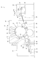
- FIG. 1 is a side view showing a printing press equipped with an electrostatic removal device according to a first embodiment of the present invention.
- FIG. 2 is a side view showing a printing press provided with an electrostatic removing device according to a second embodiment of the present invention.
- the digital printing machine 1 as a printing machine shown in FIG. 1 is configured by combining a plurality of devices.
- the plurality of apparatuses are a large-capacity supply apparatus 2, an image forming apparatus main body 3, an intermediate conveyance unit 4, a large-capacity stacker 5, and a flat stitching machine 6 in order from the right in FIG.
- a sheet 8 as a printing medium is supplied from the sheet stacking units 2a to 2c of the large-capacity supply device 2 and the supply cassettes 21 to 23 of the image forming apparatus main body 3 to the printing unit 12 of the image forming apparatus main body 3.
- the supply part 24 which supplies is comprised.
- the image forming apparatus main body 3 includes the discharge unit 19 of the image forming apparatus main body 3, the belt-type transport device 36 and the sub discharge tray 35 of the large capacity stacker 5, and the main tray 38 and the sub tray 39 of the flat stitching machine 6.
- a discharge unit is configured to discharge the sheet 8 printed by the printing unit 12.
- the digital printing machine 1 includes a conveyance path 7 through which a sheet 8 from the supply unit 24 through the printing unit 12 to the discharge unit is conveyed.
- a part of the transport path 7 is indicated by a thick line in FIG.
- the thick line portion is configured to feed the sheet 8 with a pair of rotating rollers (not shown).
- the conveyance path 7 is a path along which the sheet 8 moves. Therefore, in addition to the thick line portion, the upper part of the sheet 8 stacked on the supply unit 2 and the discharge unit is also included in the conveyance path 7.
- the conveyance path 7 is a conveyance device such as a chain delivery that conveys the sheet 8 by a chain by gripping a belt, a conveyance cylinder, a suction pad (suction port), and a leading end of the sheet 8 with a gripping claw device called a claw hook. It may be configured.
- the large-capacity supply device 2 is a device for storing sheets 8 before printing and sending a large amount of sheets 8 to the image forming apparatus main body 3 to be described later.
- the large-capacity supply device 2 includes three sheet stacking units 2a to 2c as supply sheet stacking units arranged in the vertical direction, and sheets 8 from the sheet stacking units 2a to 2c one by one to the thick line portion of the conveyance path 7.
- a feeding mechanism (not shown) for feeding.
- a supply mechanism is provided for each of the sheet stacking units 2a to 2c.
- the image forming apparatus main body 3 is a so-called dry electrophotographic apparatus.
- An image reading unit 11 and a printing unit 12 are provided on the upper portion of the image forming apparatus main body 3.
- the image reading unit 11 is a device for reading an image of a document, and is positioned at the upper end of the image forming apparatus main body 3.
- the image reading unit 11 includes an automatic document feeder 13 for automatically feeding a document.
- the printing unit 12 is located below the image reading unit 11.
- the printing unit 12 supplies a photosensitive drum 14, an image writing unit 15 that forms a latent image by irradiating the photosensitive drum 14 with laser light, and supplies toner (not shown) to the photosensitive drum 14.
- a developing unit 16, a transfer unit 17 that transfers toner to the sheet 8, a fixing device 18 that fixes an image, and the like are provided.
- the sheet 8 printed by the printing unit 12 is conveyed by the conveyance path 7 and is sent from the discharge unit 19 of the image forming apparatus main body 3 to the intermediate conveyance unit 4 described later.
- the discharge unit 19 forms a discharge unit from which the printed sheet 8 is discharged.
- three supply cassettes 21 to 23 for storing the sheet 8 before printing and supplying it to the printing unit 12 are provided.
- These supply cassettes 21 to 23 constitute the supply unit 24 of the digital printing machine 1 together with the three sheet stacking units 2a to 2c of the large-capacity supply device described above.
- a reversing unit 25 for reversing the front and back of the sheet 8 is provided between the uppermost supply cassette 21 of the three supply cassettes 21 to 23 and the conveyance path 7.
- the conveyance path 7 in the image forming apparatus main body 3 includes three supply cassettes 21 to 23 and a merge unit 26 into which the sheet 8 sent from the reversing unit 25 is carried. Accordingly, the sheet 8 can be supplied also from the three supply cassettes 21 to 23 and the reversing unit 25 to the conveyance path 7 in the image forming apparatus main body 3.
- a first electrostatic removing device 31 is provided in the vicinity of the upper portion of the junction 26. That is, the first electrostatic removal device 31 is disposed so as to face the junction 26 of the conveyance path 7.
- the first electrostatic removal device 31 includes a soft X-ray generation source (not shown) that generates soft X-rays 32, and a soft X-ray irradiation unit 31a for regulating the direction in which the soft X-rays 32 are irradiated. And.
- the soft X-ray generation source is accommodated in the soft X-ray irradiation unit 31a.
- the soft X-ray generation source in this embodiment generates soft X-rays 32 having a wavelength of 0.1 nm to several tens of nm.
- the soft X-ray irradiation unit 31a is supported on a frame (not shown) of the image forming apparatus main body 3 by a bracket (not shown), and applies soft X-rays 32 to the sheet 8 on the downstream side in the transport direction from the joining unit 26. Irradiate.
- the first electrostatic removing device 31 can be provided in the large-capacity supply device 2. That is, as indicated by a two-dot chain line in FIG. 1, the first electrostatic removing device 31 can be provided in each of the sheet stacking portions 2a to 2c of the large capacity supply device 2.
- the first static eliminating device 31 is provided in the sheet stacking units 2a to 2c, the first static eliminating device 31 is positioned above the sheet outlet so that the entire area of the sheet 8 can be irradiated with the soft X-rays 32. .
- the upper surfaces of the three sheet stacking units 2a to 2c and the three supply cassettes 21 to 23 are paths through which the uppermost sheet 8 moves, and are included in the transport path 7 through which the sheets 8 are transported.
- the first electrostatic removing device 31 is disposed so as to face the upper surfaces of the sheet stacking portions 2a to 2c and / or the supply cassettes 21 to 23 which are a part of the conveyance path 7.
- a second electrostatic removing device 33 is provided in the discharge unit 19 where the printed sheet 8 is discharged from the image forming apparatus main body 3.
- the second electrostatic removal device 33 is disposed facing the conveyance path 7 in the discharge unit 19.
- the second electrostatic removal device 33 is equivalent to the first electrostatic removal device 31.
- the soft X-ray irradiation unit 33a of the second electrostatic removal device 33 is supported by the frame of the image forming apparatus main body 3 via a bracket (not shown), and is a printed sheet conveyed through the conveyance path 7. 8 is irradiated with soft X-rays 32.
- the intermediate transport unit 4 is a device for selectively reversing the front end and the rear end of the sheet 8 in the transport direction.
- the intermediate transport unit 4 includes a storage unit 4a that temporarily stores the sheet 8 in a state of extending in the vertical direction.
- the large-capacity stacker 5 includes a sheet stacking table 34 and a sub discharge tray 35 as a discharge sheet stacking unit on which the printed sheets 8 are placed.
- the sheet stacking table 34 is movable in the vertical direction inside the large-capacity stacker 5.
- a belt-type transport device 36 for horizontally pulling out the sheet 8 from the transport path 7 to above the sheet stacking table 34 is provided.
- the sub discharge tray 35 is provided at the upper end of the large capacity stacker 5.
- the sub discharge tray 35 and the belt-type transport device 36 can be provided with a second electrostatic removal device 33 as shown by a two-dot chain line.
- the second electrostatic removal device 33 provided on the sub discharge tray 35 irradiates the upper surface of the sheet 8 discharged from the conveyance path 7 to the sub discharge tray 35 with soft X-rays 32.
- the second static eliminating device 33 provided in the belt type conveying device 36 irradiates the upper surface of the sheet 8 drawn in the horizontal direction by the belt type conveying device 36 with soft X-rays 32.
- the upper surfaces of the belt-type conveyance device 36 and the sub discharge tray 35 are paths through which the sheet 8 moves, and are included in the conveyance path 7 in which the sheet 8 is conveyed.
- the second electrostatic removal device 33 is disposed so as to face the upper surface of the belt-type transport device 36 and / or the sub discharge tray 35 that are part of the transport path 7.
- the flat stitching machine 6 has a stacker unit 37 inside.
- the flat stitching machine 6 further includes a main tray 38 and a sub-tray 39 as a discharge sheet stacking unit on which the printed sheets 8 are placed.
- the stacker unit 37 overlaps and binds a plurality of sheets 8, and discharges the bound sheets 8 to the main tray 38.
- the main tray 38 and the sub-tray 39 can be provided with a second electrostatic removal device 33 as indicated by a two-dot chain line.
- the second static eliminating device 33 provided on the main tray 38 irradiates the upper surface of the sheet 8 discharged to the main tray 38 with soft X-rays 32.
- the second static eliminator 33 provided on the sub-tray 39 irradiates the upper surface of the sheet 8 discharged to the sub-tray 39 with soft X-rays 32.
- the upper surfaces of the main tray 38 and the sub-tray 39 are paths through which the sheet 8 moves and are included in the transport path 7 through which the sheet 8 is transported.
- the second static eliminating device 33 is disposed so as to face the upper surface of the main tray 38 and / or the sub-tray 39 that are part of the transport path 7.
- the image forming apparatus main body 3 When the second electrostatic removing device 33 is provided on the belt type conveying device 36 and the sub discharge tray 35 of the large capacity stacker 5 and the main tray 38 and the sub tray 39 of the flat stitching machine 6, respectively, the image forming apparatus main body 3 is provided. There is no need to provide the second electrostatic removal device 33 in the discharge portion 19 of the battery. In this case, the belt-type transport device 36 and the sub discharge tray 35 of the large-capacity stacker 5 and the main tray 38 and the sub tray 39 of the flat stitching machine 6 constitute a discharge unit for discharging the printed sheet 8. .
- the second electrostatic removal device 33 provided on the sub discharge tray 35 of the large-capacity stacker 5 and the main tray 38 and the sub tray 39 of the flat stitching machine 6 can be assembled to the tray in the process of manufacturing these trays. it can.
- the second electrostatic removal device 33 is assembled to the large-capacity stacker 5 and the flat binding machine 6, these trays are directly attached to these trays or via mounting brackets.
- a so-called retrofit can be adopted.
- the first static elimination device 31, the second static elimination device 33 provided in the image forming apparatus main body 3, and the second static elimination device 33 provided in the belt-type conveyance device 36 are also retrofitted. Can be configured to be installed.
- the soft X-rays 32 When the first static elimination device 31 and the second static elimination device 33 irradiate the soft X-rays 32, the soft X-rays 32 are scattered by the molecules in the air, and the energy absorbed at that time Electrons are excited and emitted. Molecules that have released electrons are positively ionized. When ionized electrons collide with a nearby neutral gas and adsorb, the molecules are negatively ionized. In this way, positive ions and negative ions are evenly generated in the region irradiated with the soft X-rays 32. The force attracting the positive ions and the negative ions is attracted to the sheet 8 charged with static electricity, and the static electricity is removed.
- the electrostatic removal devices 31 and 33 are configured to irradiate soft X-rays 32 over the entire width of the sheet 8.
- the conveyed sheet 8 passes through an area where the soft X-ray 32 is irradiated to the entire width of the sheet 8. become.
- the entire surface of the sheet 8 is irradiated with the soft X-rays 32 and the entire sheet 8 is discharged.
- the sheet 8 from which static electricity has been removed by the first static eliminating device 31 is carried into the printing unit 12 of the image forming apparatus main body 3.
- the sheet 8 is printed by the printing unit 12 of the image forming apparatus main body 3 and sent to the discharge unit 19.
- the printed sheet 8 may be charged with static electricity.
- the second electrostatic removal device 33 is provided in the image forming apparatus main body 3, the static electricity is removed by the second electrostatic removal device 33 when the sheet 8 is discharged from the image forming apparatus main body 3.
- the second electrostatic removal device 33 is provided not in the image forming apparatus main body 3 but in the large-capacity stacker 5 or the flat stitching machine 6, the sheet 8 moves below the second electrostatic removal device 33.
- the static electricity is removed, and the sheet 8 is placed on the sheet stacking table 34 or the tray without being charged with static electricity.
- the first electrostatic removal device 31 and the second electrostatic removal device 33 in this embodiment are configured such that when the sheet 8 is conveyed on the conveyance path 7 and passes near the soft X-ray irradiation unit 31a. 8 is irradiated with soft X-rays 32 to remove static electricity from the sheet 8. Therefore, according to this embodiment, it is possible to provide an electrostatic eliminator for a digital printing machine that can reliably remove static electricity and can eliminate problems caused by static electricity that occur in the digital printing machine 1.
- the second electrostatic removal device 33 in this embodiment is provided in the discharge unit 19 where the printed sheet 8 in the digital printing machine 1 is discharged. For this reason, since the static electricity is removed when the sheet 8 is discharged to the discharge unit 19, the sheet 8 after discharge becomes easy to handle. That is, when post-processing is performed on the printed sheet 8, the sheet 8 is not attracted to other sheets 8 or other members by static electricity, and therefore, for example, the sheet 8 can be easily folded and bound. Can do. Therefore, according to this embodiment, it is possible to provide an electrostatic eliminator for a digital printing machine that can perform post-processing without causing problems due to static electricity in the digital printing machine 1.
- the first electrostatic removal device 31 in this embodiment is provided in the supply unit 24 that stores the sheet 8 before printing in the digital printing machine 1 and supplies it to the printing unit 12. For this reason, since the sheet 8 from which static electricity has been removed is sent from the supply unit 24 to the printing unit 12, poor conveyance of the sheet 8 due to static electricity is less likely to occur upstream of the printing unit 12 in the conveyance direction of the sheet 8. Therefore, since the sheet 8 can be smoothly and accurately sent to the printing unit 12, it is possible to provide an electrostatic eliminator for a digital printing machine that can improve the productivity and print quality of the digital printing machine 1.
- the digital printing machine 1 in this embodiment includes a first electrostatic removal device 31 and a second electrostatic removal device 33 that irradiate soft X-rays 32 toward the sheet 8. For this reason, according to this embodiment, it is possible to provide a digital printing machine in which the conveyance failure of the sheet 8 due to static electricity and the handling failure of the sheet 8 do not occur in the post-processing step.
- both the first static elimination device 31 and the second static elimination device 33 do not necessarily have to be equipped.
- at least the second electrostatic removal device 33 can be provided among the first electrostatic removal device 31 and the second electrostatic removal device 33.
- corona discharge type electrostatic discharger There is a corona discharge type electrostatic discharger.
- an AC voltage is applied to the electrodes to perform corona discharge, and positive ions and negative ions are generated alternately.
- the corona discharge type electrostatic eliminator a configuration is adopted in which ions generated in the vicinity of the electrode are placed on the wind and sent over a wide range, but it is difficult to send the ions to the entire area of the sheet 8. For the above reasons, even if a corona discharge type electrostatic eliminator is used in the printing press, the static electricity charged on the sheet 8 cannot always be completely removed.
- positive ions and negative ions are evenly generated in the region irradiated with the soft X-rays 32 from the electrostatic removal devices 31 and 33. Since positive ions and negative ions are generated uniformly, the sheet 8 is not reversely charged. Further, since ions are generated in the vicinity of the sheet 8 irradiated with the soft X-rays 32, it is not necessary to send the ions on the wind. Therefore, according to this embodiment, static electricity charged on the sheet 8 can be reliably removed.
- the digital printer 41 shown in FIG. 2 is an ink jet digital printer.
- the sheet 8 is conveyed to the printing unit 43 from the feeder unit 42 located on the rightmost side, and printing is performed on one side or both sides of the sheet 8 in the printing unit 43.
- the sheet 8 printed by the printing unit 43 is sent to the delivery unit 44 and discharged to a delivery pile 45 as a discharge sheet stacking unit.
- the feeder unit 42 has a structure in which the sheet 8 is transferred to the feeder board 48 by the soccer 47 from the feeder pile 46 as the supply sheet stacking unit.
- the feeder unit 42 and the feeder board 48 constitute a supply unit 24 that supplies the printing unit 12 with a sheet 8 as a printing medium.
- the soccer 47 is connected to the intermittent supply valve 49 and operates in one of a form in which the seat 8 is continuously fed and a form in which the seat 8 is intermittently fed.
- the printing unit 43 includes a supply-side transfer cylinder 51 to which the sheet 8 supplied from the feeder unit 42 is conveyed by the supply-side swing device 50, a printing cylinder 52 to which the sheet 8 is fed from the supply-side transfer cylinder 51, and after printing And a plurality of conveying cylinders 53 to 56 for feeding the sheet 8.
- the printing unit 43 further includes a paper presence / absence detection sensor 57 positioned on the downstream side in the transport direction from the supply-side transfer cylinder 51, and first to fourth inkjet nozzles positioned on the downstream side in the transport direction from the paper presence / absence detection sensor 57.
- the heads 58 to 61 and an ink drying lamp 62 positioned downstream of the fourth inkjet nozzle head 61 in the transport direction are provided.
- the first to fourth inkjet nozzle heads 58 to 61 are for spraying and applying ink to the sheet 8.
- the first to fourth ink jet nozzle heads 58 to 61 constitute a printing unit 12 that performs printing on the sheet 8.
- the ink drying lamp 62 is for curing the ink applied to the sheet 8 by the first to fourth inkjet nozzle heads 58 to 61.
- the plurality of transport cylinders described above include a first discharge-side transfer cylinder 53 that receives the sheet 8 from the printing cylinder 52, a second discharge-side transfer cylinder 54 that receives the sheet 8 from the first discharge-side transfer cylinder 53, and These are a sheet discharge cylinder 55 and a pre-inversion double cylinder 56 that receive the sheet 8 from the second discharge side transfer cylinder 54.
- a first discharge-side transfer cylinder 53 that receives the sheet 8 from the printing cylinder 52
- a second discharge-side transfer cylinder 54 that receives the sheet 8 from the first discharge-side transfer cylinder 53
- These are a sheet discharge cylinder 55 and a pre-inversion double cylinder 56 that receive the sheet 8 from the second discharge side transfer cylinder 54.
- the sheet 8 is transferred from the second discharge side transfer cylinder 54 to the sheet discharge cylinder. 55, and sent to the delivery pile 45 by the delivery belt 58.
- the delivery pile 45 constitutes a discharge unit 19 from which the sheet 8 printed by the printing unit 12 is discharged.
- a discharge path 55 in which the sheet 8 is conveyed is configured by the discharge cylinder 55, the pre-reversal double cylinder 56, the delivery belt 58, the delivery pile 45, and the like.
- the first electrostatic removing device 31 is disposed near the upper end of the upstream side of the feeder board 48.
- a second electrostatic removal device 33 is disposed between the ink drying lamp 62 and the first discharge side transfer cylinder 53 and in the vicinity of the delivery belt 58 in the vicinity of the downstream end in the transport direction. Yes. That is, the first electrostatic removal device 31 and the second electrostatic removal device 33 are arranged facing the transport path 7.
- the first electrostatic removal device 31 irradiates the upper surface of the sheet 8 moving on the feeder board 48 with soft X-rays 32.
- the first static eliminating device 31 is provided in the supply unit 24 of the digital printing machine 1, whereby the sheet 8 from which static electricity has been removed is sent from the feeder board 48 to the printing unit 12. For this reason, poor conveyance of the sheet 8 due to static electricity is less likely to occur upstream of the printing unit 12 in the conveyance direction of the sheet 8. Therefore, according to this embodiment, since the sheet 8 can be smoothly and accurately sent to the printing unit 12, electrostatic removal for a digital printing machine that can improve the productivity and print quality of the digital printing machine 1. An apparatus can be provided.
- the second electrostatic removal device 33 provided between the ink drying lamp 62 and the first discharge side transfer cylinder 53 irradiates the surface or the back surface of the sheet 8 after the ink is cured with soft X-rays 32. . Even if the printed sheet 8 is charged with static electricity, the static electricity is removed upstream of the first discharge side transfer cylinder 53. For this reason, the conveyance after printing can be performed favorably.
- the second electrostatic removal device 33 provided near the upper part of the delivery belt 58 irradiates the upper surface of the sheet 8 placed on the delivery belt 58 and conveyed with soft X-rays 32. For this reason, since the static electricity is removed when the sheet 8 is discharged to the delivery pile 45, the discharged sheet 8 can be easily handled.
- the sheet 8 When post-processing is performed on the sheet 8 after printing, the sheet 8 is not attracted to other sheets 8 or other members by static electricity, so that the sheet 8 can be easily folded, bound, and the like. . Therefore, also in this embodiment, it is possible to provide an electrostatic eliminator for a digital printing machine that can perform post-processing without causing trouble due to static electricity in the digital printing machine 1.
- the conveyance failure of the sheet 8 due to static electricity since the first static eliminator 31 and the second static eliminator 33 that remove static electricity from the sheet 8 are provided, the conveyance failure of the sheet 8 due to static electricity, In addition, it is possible to provide a digital printing machine that does not cause poor handling of the sheet 8 in the post-processing step.
- the present invention is not limited to such a limitation.
- the second electrostatic removal device 33 can be provided only at least near the upper portion of the delivery pile 58 among the three electrostatic removal devices.
- the soft X-ray irradiation device is provided in the digital printing machine.
- the present invention is not limited to a digital printing machine, and may be applied to various printing machines such as an offset printing machine, a gravure printing machine, and a screen printing machine.
- the sheet supply unit and the discharge unit are optimal for the location where the soft X-ray irradiation device is provided, and may be provided in the printing unit as necessary.
Landscapes
- Health & Medical Sciences (AREA)
- General Health & Medical Sciences (AREA)
- Toxicology (AREA)
- Physics & Mathematics (AREA)
- General Physics & Mathematics (AREA)
- Feeding Of Articles By Means Other Than Belts Or Rollers (AREA)
Abstract
静電除去装置(31,33)は、シート(8)に軟X線(32)を照射する軟X線照射部(31a)を備えている。これらの静電除去装置(31,33)は、デジタル印刷機(1)においてシート(8)が搬送される搬送路(7)に面して配置されている。シート(8)が搬送路(7)を搬送されて軟X線照射部(31a)の近傍を通過するときに、シート(8)に軟X線(32)が照射され、シート(8)の静電気が除去される。これにより、静電気が確実に除去され、デジタル印刷機(1)において生じる静電気による不具合が解消される。
Description
本発明は、印刷機に取付けられて静電気を除去する印刷機用静電除去装置およびこの静電除去装置を備えた印刷機に関するものである。
本発明に関連する印刷機の一例として、特許文献1に開示されたデジタル印刷機がある。このデジタル印刷機は、刷版を作ることなく、デジタル技術を使用して商業印刷を行うものである。近年のこの種のデジタル印刷機においては、印刷後に後加工を連続して行うことが求められている。この後加工としては、折り加工や、裁断加工、製本加工などがある。
しかし、印刷を施された紙などのシートは、摩擦等によって静電気が帯電してしまうことがあり、後加工を行い難いものであった。トナー式のデジタル印刷機では、静電気を利用してトナーを転写するために、シートへの帯電は避けられず、静電気による不具合の発生が特に多い。このような静電気による不具合は、デジタル印刷機だけの問題でなく、オフセット印刷機やグラビア印刷機、スクリーン印刷機など各種印刷機でも発生する問題である。特に被印刷物としてフィルムを使用する場合、静電気の対策は重要課題である。
本発明の目的は、静電気を確実に除去し、印刷機において生じる静電気による不具合を解消することにある。
この目的を達成するために、本発明の印刷機用静電除去装置は、シートに軟X線を照射する軟X線照射部を備え、印刷機においてシートが搬送される搬送路に面して配置されるものである。
本発明の印刷機は、シートに印刷を施す印刷部と、シートを蓄えて印刷部にシートを供給する供給部と、印刷部により印刷されたシートが排出される排出部と、シートに軟X線を照射する軟X線照射部を備え供給部から印刷部を経て排出部に至るシートが搬送される搬送路に面して配置された印刷機用静電除去装置とを備えるものである。
本発明における静電除去装置は、シートが搬送路を搬送されて軟X線照射部の近傍を通過するときに、このシートに軟X線を照射し、シートの静電気を除去する。したがって、本発明によれば、静電気を確実に除去でき、印刷機において生じる静電気による不具合を解消することが可能となる。
(第1の実施の形態)
以下、本発明に係る印刷機用静電除去装置および印刷機の第1の実施の形態について、図1を用いて詳細に説明する。
以下、本発明に係る印刷機用静電除去装置および印刷機の第1の実施の形態について、図1を用いて詳細に説明する。
図1に示す印刷機としてのデジタル印刷機1は、複数の装置を組み合わせて構成されている。複数の装置とは、図1において右から順に大容量供給装置2と、画像形成装置本体3と、中間搬送ユニット4と、大容量スタッカ5と、平綴じ機6などである。後述するように、大容量供給装置2のシート積載部2a~2cと、画像形成装置本体3の供給カセット21~23とから、画像形成装置本体3の印刷部12に被印刷媒体としてのシート8を供給する供給部24が構成される。また、画像形成装置本体3の排出部19と、大容量スタッカ5のベルト式搬送装置36およびサブ排出トレイ35と、平綴じ機6のメイントレイ38およびサブトレイ39とから、画像形成装置本体3の印刷部12により印刷されたシート8が排出される排出部が構成される。
デジタル印刷機1は、供給部24から印刷部12を経て上記排出部に至るシート8が搬送される搬送路7を備えている。この搬送路7の一部が図1中に太線で示されている。この太線部分は、一対の回転するローラ(図示せず)によってシート8を挟んで送るように構成されている。
搬送路7は、言い換えればシート8が移動する経路である。したがって、太線部分の他に、供給部2および上記排出部に積載されているシート8の上方も搬送路7に含まれる。この搬送路7は、図示しないベルト、搬送胴、吸着パッド(吸口)、シート8の先端を爪竿と呼ばれるくわえ爪装置で把持してチェーンにより当該シート8を搬送するチェーンデリバリーなどの搬送装置で構成されていても良い。
大容量供給装置2は、印刷前のシート8を蓄えて大量のシート8を後述する画像形成装置本体3に送るための装置である。この大容量供給装置2は、上下方向に並ぶ3つの供給シート積載部としてのシート積載部2a~2cと、これらのシート積載部2a~2cからシート8を1枚ずつ搬送路7の太線部分に送る供給機構(図示せず)とを備えている。供給機構は、シート積載部2a~2c毎に設けられている。
画像形成装置本体3は、いわゆる乾式電子写真方式の装置である。この画像形成装置本体3の上部には、画像読取部11と印刷部12とが設けられている。画像読取部11は、原稿の画像を読み取るための装置で、画像形成装置本体3の上端部に位置付けられている。この画像読取部11は、原稿を自動で送るための自動原稿送り装置13を備えている。
印刷部12は、画像読取部11の下方に位置している。この印刷部12は、感光体ドラム14と、この感光体ドラム14にレーザ光を照射して潜像を形成する画像書込部15と、感光体ドラム14にトナー(図示せず)を供給する現像部16と、シート8にトナーを転写させる転写部17と、画像を定着させる定着装置18などを備えている。この印刷部12で印刷が施されたシート8は、搬送路7によって搬送され、画像形成装置本体3の排出部19から後述する中間搬送ユニット4に送られる。この実施の形態においては、この排出部19により、印刷されたシート8が排出される排出部が構成される。
画像形成装置本体3の下部には、印刷前のシート8を蓄えて印刷部12に供給する3個の供給カセット21~23が設けられている。これらの供給カセット21~23は、上述した大容量供給装置の3つのシート積載部2a~2cとともにこのデジタル印刷機1の供給部24を構成する。3個の供給カセット21~23のうち最も上に位置する供給カセット21と搬送路7との間には、シート8の表裏を反転させるための反転部25が設けられている。
画像形成装置本体3内の搬送路7は、3個の供給カセット21~23および反転部25から送られたシート8が搬入される合流部26を有している。したがって、3個の供給カセット21~23および反転部25からも画像形成装置本体3内の搬送路7にシート8を供給することが可能である。
この合流部26の上方近傍には、第1の静電除去装置31が設けられている。すなわち、第1の静電除去装置31は、搬送路7の合流部26に面して配置されている。この第1の静電除去装置31は、軟X線32を発生させる軟X線発生源(図示せず)と、軟X線32が照射される方向を規制するための軟X線照射部31aとを備えている。軟X線発生源は、軟X線照射部31aに収容されている。この実施の形態における軟X線発生源は、波長が0.1nm~数十nmの軟X線32を発生させるものである。軟X線照射部31aは、図示していないブラケットによって画像形成装置本体3のフレーム(図示せず)に支持されており、合流部26より搬送方向の下流側でシート8に軟X線32を照射する。
画像形成装置本体3に設ける代わりに、大容量供給装置2に第1の静電除去装置31を設けることができる。すなわち、図1中に二点鎖線で示すように、大容量供給装置2のシート積載部2a~2cにそれぞれ第1の静電除去装置31を設けることができる。シート積載部2a~2cに第1の静電除去装置31を設けるにあたっては、シート8の全域に軟X線32を照射できるように、シート出口の上方に第1の静電除去装置31を位置付ける。なお、この場合は、図示してはいないが、画像形成装置本体3の3個の供給カセット21~23のシート出口の上方にも第1の静電除去装置31を設けることが望ましい。ここで、3個のシート積載部2a~2cおよび3個の供給カセット21~23の上面は、最上層のシート8が移動する経路であり、シート8が搬送される搬送路7に含まれる。すなわち、第1の静電除去装置31は、搬送路7の一部であるシート積載部2a~2cおよび/または供給カセット21~23の上面に面して配置される。
画像形成装置本体3から印刷後のシート8が排出される排出部19には、第2の静電除去装置33が設けられている。この第2の静電除去装置33は、排出部19における搬送路7に面して配置されている。この第2の静電除去装置33は、第1の静電除去装置31と同等のものである。この第2の静電除去装置33の軟X線照射部33aは、図示していないブラケットを介して画像形成装置本体3のフレームに支持されており、搬送路7を搬送される印刷後のシート8の上面に軟X線32を照射する。
中間搬送ユニット4は、シート8の搬送方向の先端と後端とを選択的に反転させるための装置である。この中間搬送ユニット4は、シート8を上下方向に延びる状態で仮に収納する収納部4aを備えている。
大容量スタッカ5は、印刷後のシート8が載置される排出シート積載部としての、シート積載台34およびサブ排出トレイ35を備えている。シート積載台34は、大容量スタッカ5の内部で上下方向に移動可能である。シート積載台34の上方には、シート8を搬送路7からシート積載台34の上方へ水平に引き出すためのベルト式搬送装置36が設けられている。
サブ排出トレイ35は、大容量スタッカ5の上端部に設けられている。このサブ排出トレイ35と、ベルト式搬送装置36とには、二点鎖線で示すように、第2の静電除去装置33を設けることができる。サブ排出トレイ35に設けられた第2の静電除去装置33は、搬送路7からサブ排出トレイ35に排出されるシート8の上面に軟X線32を照射する。ベルト式搬送装置36に設けられた第2の静電除去装置33は、ベルト式搬送装置36によって水平方向に引かれたシート8の上面に軟X線32を照射する。ここで、ベルト式搬送装置36およびサブ排出トレイ35の上面は、シート8が移動する経路であり、シート8が搬送される搬送路7に含まれる。すなわち、第2の静電除去装置33は、搬送路7の一部であるベルト式搬送装置36および/またはサブ排出トレイ35の上面に面して配置される。
平綴じ機6は、内部にスタッカユニット37を有している。平綴じ機6は更に、印刷後のシート8が載置される排出シート積載部としての、メイントレイ38およびサブトレイ39を備えている。スタッカユニット37は、複数枚のシート8を重ねて綴じるもので、綴じられた複数枚のシート8をメイントレイ38に排出する。
メイントレイ38およびサブトレイ39には、二点鎖線で示すように、第2の静電除去装置33を設けることができる。メイントレイ38に設けられた第2の静電除去装置33は、メイントレイ38に排出されるシート8の上面に軟X線32を照射する。サブトレイ39に設けられた第2の静電除去装置33は、サブトレイ39に排出されるシート8の上面に軟X線32を照射する。ここで、メイントレイ38およびサブトレイ39の上面は、シート8が移動する経路であり、シート8が搬送される搬送路7に含まれる。すなわち、第2の静電除去装置33は、搬送路7の一部であるメイントレイ38および/またはサブトレイ39の上面に面して配置される。
大容量スタッカ5のベルト式搬送装置36およびサブ排出トレイ35と、平綴じ機6のメイントレイ38およびサブトレイ39とにそれぞれ第2の静電除去装置33が設けられる場合は、画像形成装置本体3の排出部19に第2の静電除去装置33を設ける必要がなくなる。この場合は、大容量スタッカ5のベルト式搬送装置36およびサブ排出トレイ35と、平綴じ機6のメイントレイ38およびサブトレイ39とにより、印刷されたシート8が排出される排出部が構成される。
大容量スタッカ5のサブ排出トレイ35と、平綴じ機6のメイントレイ38およびサブトレイ39とに設けられる第2の静電除去装置33は、これらのトレイを製造する工程でトレイに組付けることができる。また、この第2の静電除去装置33は、これらのトレイの製造が完了して大容量スタッカ5および平綴じ機6に組付けられた後に、これらのトレイに直接あるいは取付用ブラケットを介していわゆる後付けで取付けられる構成を採ることができる。なお、第1の静電除去装置31や、画像形成装置本体3に設けられる第2の静電除去装置33や、ベルト式搬送装置36に設けられる第2の静電除去装置33も、後付けで取付けられる構成を採ることができる。
第1の静電除去装置31および第2の静電除去装置33が軟X線32を照射すると、軟X線32が空気中の分子によって散乱され、その際に吸収されたエネルギーによって分子中の電子が励起・放出される。電子を放出した分子はプラスイオン化する。電離した電子が近傍の中性ガスに衝突し、吸着すると、その分子はマイナスイオン化する。このようにして、軟X線32が照射された領域にプラスイオンとマイナスイオンとが均等に生成される。プラスイオンとマイナスイオンとが引き合う力で、静電気を帯びたシート8に吸い寄せられ、その静電気が除去される。
静電除去装置31,33は、シート8の全幅にわたって軟X線32を照射するよう構成されている。このような静電除去装置31,33をシート8の搬送路7の近傍に設けることにより、搬送されるシート8が、当該シート8の全幅に軟X線32が照射される領域を通過することになる。その結果、シート8の全面に軟X線32が照射されて、シート8全体が除電されることになる。
このように構成されたデジタル印刷機1においては、第1の静電除去装置31によって静電気が除去されたシート8が画像形成装置本体3の印刷部12に搬入される。このシート8は、画像形成装置本体3の印刷部12によって印刷されて排出部19に送られる。印刷後のシート8は、静電気を帯びていることがある。第2の静電除去装置33が画像形成装置本体3に設けられている場合、この静電気は、シート8が画像形成装置本体3から排出されるときに第2の静電除去装置33によって除去される。第2の静電除去装置33が画像形成装置本体3ではなく大容量スタッカ5や平綴じ機6に設けられている場合は、シート8が第2の静電除去装置33の下方を移動することにより静電気が除去され、静電気を帯びていない状態でシート8がシート積載台34やトレイの上に載せられる。
この実施の形態における第1の静電除去装置31と第2の静電除去装置33は、シート8が搬送路7を搬送されて軟X線照射部31aの近傍を通過するときに、このシート8に軟X線32を照射し、シート8の静電気を除去するものである。したがって、この実施の形態によれば、静電気を確実に除去でき、デジタル印刷機1において生じる静電気による不具合を解消可能なデジタル印刷機用静電除去装置を提供することができる。
この実施の形態における第2の静電除去装置33は、デジタル印刷機1における印刷後のシート8が排出される排出部19に設けられている。このため、シート8が排出部19に排出されるときに静電気が除去されるから、排出後のシート8の取り扱いが容易になる。すなわち、印刷後のシート8に後加工を施すときに、シート8が他のシート8や他の部材に静電気によって吸着されることがないから、例えばシート8の折り曲げ、綴じ込みなどを容易に行うことができる。したがって、この実施の形態によれば、デジタル印刷機1において静電気による不具合が発生することなく後加工を行うことが可能になるデジタル印刷機用静電除去装置を提供することができる。
この実施の形態における第1の静電除去装置31は、デジタル印刷機1における印刷前のシート8を蓄えて印刷部12に供給する供給部24に設けられている。このため、静電気が除去されたシート8が供給部24から印刷部12に送られるから、印刷部12よりシート8の搬送方向の上流側で静電気によるシート8の搬送不良が発生し難くなる。したがって、シート8を円滑にかつ精度良く印刷部12に送ることができるから、デジタル印刷機1の生産性と印刷品質とを向上可能なデジタル印刷機用静電除去装置を提供することができる。
この実施の形態におけるデジタル印刷機1は、軟X線32をシート8に向けて照射する第1の静電除去装置31と第2の静電除去装置33とを備えている。このため、この実施の形態によれば、静電気によるシート8の搬送不良や、後加工を行う工程でシート8の取り扱い不良が起こることがないデジタル印刷機を提供することができる。なお、第1の静電除去装置31と、第2の静電除去装置33は、必ずしも両方とも装備する必要はない。例えば、第1の静電除去装置31と第2の静電除去装置33とのうち、少なくとも第2の静電除去装置33のみを備えることができる。
静電除去装置としては、コロナ放電式のものがある。コロナ放電式の静電除去装置では、電極に交流電圧を印加してコロナ放電を行ない、プラスイオンとマイナスイオンとを交互に発生させる。このため、シート8に帯電する電荷の極性によっては、電荷を中和して除電するどころか、逆に帯電量を増加させる「逆帯電」を起こす可能性がある。また、コロナ放電式の静電除去装置では、電極の近傍で発生したイオンを風に乗せて広い範囲に送る構成が採られているものの、イオンをシート8の全域に送ることは難しい。以上の理由から、印刷機にコロナ放電式の静電除去装置を用いても、シート8に帯電した静電気を完全に除去できるとは限らない。
これに対し、この実施の形態においては、上述したとおり、静電除去装置31,33から軟X線32が照射された領域にプラスイオンとマイナスイオンとが均等に生成される。プラスイオンとマイナスイオンとが均等に生成されるため、シート8に逆帯電は生じない。また、軟X線32が照射されたシート8の近傍でイオンが生成されるので、イオンを風に乗せて送る必要がない。したがって、この実施の形態によれば、シート8に帯電した静電気を確実に除去することができる。
(第2の実施の形態)
本発明に係る印刷機用静電除去装置およびデジタル印刷機の第2の実施の形態について、図2を用いて説明する。図2において、図1によって説明したものと同一もしくは同等の部材については、同一符号を付し詳細な説明を適宜省略する。
本発明に係る印刷機用静電除去装置およびデジタル印刷機の第2の実施の形態について、図2を用いて説明する。図2において、図1によって説明したものと同一もしくは同等の部材については、同一符号を付し詳細な説明を適宜省略する。
図2に示すデジタル印刷機41は、インクジェット式のデジタル印刷機である。図2において最も右に位置するフィーダー部42から印刷ユニット43にシート8が搬送され、この印刷ユニット43においてシート8の片面または両面に印刷を施される。印刷ユニット43において印刷が施されたシート8は、デリバリー部44に送られ、排出シート積載部としてのデリバリーパイル45に排出される。
フィーダー部42は、供給シート積載部としてのフィーダーパイル46からシート8をサッカー47によってフィーダーボード48に移し替える構造のものである。この実施の形態においては、これらのフィーダー部42とフィーダーボード48とによって、印刷部12に被印刷媒体としてのシート8を供給する供給部24が構成されている。サッカー47は、間欠供給バルブ49に接続されており、シート8が連続的に送られる形態と、シート8が間欠的に送られる形態とのうちいずれか一方の形態で動作する。
印刷ユニット43は、フィーダー部42から供給されたシート8が供給側スイング装置50によって搬送される供給側渡胴51と、この供給側渡胴51からシート8が送られる印刷胴52と、印刷後のシート8を送る複数の搬送胴53~56とを備えている。印刷ユニット43は更に、供給側渡胴51より搬送方向の下流側に位置する紙有無検知センサー57と、この紙有無検知センサー57より搬送方向の下流側に位置する第1~第4のインクジェットノズルヘッド58~61と、第4のインクジェットノズルヘッド61より搬送方向の下流側に位置するインキ乾燥ランプ62とを備えている。
第1~第4のインクジェットノズルヘッド58~61は、シート8にインキを噴射して塗布するためのものである。この実施の形態においては、これらの第1~第4のインクジェットノズルヘッド58~61によって、シート8に印刷を施す印刷部12が構成されている。インキ乾燥ランプ62は、第1~第4のインクジェットノズルヘッド58~61によってシート8に塗布されたインキを硬化させるためのものである。
上述した複数の搬送胴は、印刷胴52からシート8を受け取る第1の排出側渡胴53と、この第1の排出側渡胴53からシート8を受け取る第2の排出側渡胴54と、この第2の排出側渡胴54からシート8を受け取るシート排出胴55および反転前倍胴56である。これからシート8の裏面に印刷する場合、シート8は、第2の排出側渡胴54から反転前倍胴56に搬送され、さらに反転スイング装置57によって印刷胴52に送られる。すでにシート8の表面に印刷が施され裏面には印刷しない場合や、すでにシート8の表裏両面に印刷が施された場合には、シート8は、第2の排出側渡胴54からシート排出胴55に送られ、デリバリーベルト58によってデリバリーパイル45に送られる。この実施の形態においては、このデリバリーパイル45によって、印刷部12により印刷されたシート8が排出される排出部19が構成されている。
この実施の形態においては、フィーダーパイル46と、フィーダーボード48と、供給側渡胴51と、印刷胴52と、第1の排出側渡胴53と、第2の排出側渡胴54と、シート排出胴55と、反転前倍胴56と、デリバリーベルト58、デリバリーパイル45などによって、シート8が搬送される搬送路7が構成されている。
このデジタル印刷機1においては、フィーダーボード48の上流側端部の上方近傍に第1の静電除去装置31が配置されている。また、インキ乾燥ランプ62と第1の排出側渡胴53との間と、デリバリーベルト58における搬送方向の下流側端部の上方近傍には、それぞれ第2の静電除去装置33が配置されている。すなわち、第1の静電除去装置31および第2の静電除去装置33は、搬送路7に面して配置されている。
第1の静電除去装置31は、フィーダーボード48の上を移動するシート8の上面に軟X線32を照射する。このようにデジタル印刷機1の供給部24に第1の静電除去装置31が設けられていることにより、静電気が除去されたシート8がフィーダーボード48から印刷部12に送られる。このため、印刷部12よりシート8の搬送方向の上流側で静電気によるシート8の搬送不良が発生し難くなる。したがって、この実施の形態によれば、シート8を円滑にかつ精度良く印刷部12に送ることができるから、デジタル印刷機1の生産性と印刷品質とを向上可能なデジタル印刷機用静電除去装置を提供することができる。
インキ乾燥ランプ62と第1の排出側渡胴53との間に設けられた第2の静電除去装置33は、インキが硬化した後のシート8の表面または裏面に軟X線32を照射する。印刷後のシート8が静電気を帯びていたとしても、この静電気が第1の排出側渡胴53より上流側で除去される。このため、印刷後の搬送を良好に行うことができる。
デリバリーベルト58の上方近傍に設けられた第2の静電除去装置33は、デリバリーベルト58に載せられて搬送されるシート8の上面に軟X線32を照射する。このため、シート8がデリバリーパイル45に排出されるときに静電気が除去されるから、排出後のシート8の取り扱いが容易になる。
印刷後のシート8に後加工を施すときに、シート8が他のシート8や他の部材に静電気によって吸着されることがないから、シート8の例えば折り曲げ、綴じ込みなどを容易に行うことができる。したがって、この実施の形態においても、デジタル印刷機1において静電気による不具合が発生することなく後加工を行うことが可能になるデジタル印刷機用静電除去装置を提供することができる。
また、この実施の形態であっても、シート8の静電気を除去する第1の静電除去装置31と第2の静電除去装置33とを備えているから、静電気によるシート8の搬送不良や、後加工を行う工程でシート8の取り扱い不良が起こることがないデジタル印刷機を提供することができる。
この実施の形態においては、搬送路7の3箇所に静電除去装置を設ける例を示した。しかしながら、本発明は、このような限定にとらわれることはない。たとえば、3つの静電除去装置のうち、少なくともデリバリーパイル58の上方近傍のみに第2の静電除去装置33を設けることができる。
(その他)
上述した2つの実施の形態においては、デジタル印刷機に軟X線照射装置を設けた例を説明した。しかし、本発明は、デジタル印刷機に限定されるものではなく、オフセット印刷機やグラビア印刷機、スクリーン印刷機など各種印刷機に適用しても良い。その際、軟X線照射装置を設ける箇所は、シートの供給部および排出部が最適であり、必要に応じて印刷部に設けても良い。
上述した2つの実施の形態においては、デジタル印刷機に軟X線照射装置を設けた例を説明した。しかし、本発明は、デジタル印刷機に限定されるものではなく、オフセット印刷機やグラビア印刷機、スクリーン印刷機など各種印刷機に適用しても良い。その際、軟X線照射装置を設ける箇所は、シートの供給部および排出部が最適であり、必要に応じて印刷部に設けても良い。
1…デジタル印刷機、2a~2c…シート積載部、7…搬送路、8…シート、19…排出部、21~23…供給カセット、24…供給部、31…第1の静電除去装置、31a…軟X線照射部、33…第2の静電除去装置、33a…軟X線照射部、34…シート積載台、35…サブ排出トレイ、38…メイントレイ、39…サブトレイ、45…デリバリーパイル。
Claims (6)
- シートに軟X線を照射する軟X線照射部を備え、印刷機においてシートが搬送される搬送路に面して配置されていることを特徴とする印刷機用静電除去装置。
- 請求項1記載の印刷機用静電除去装置において、
前記印刷機は、印刷されたシートが排出される排出部を含み、
前記軟X線照射部は、前記排出部に設けられていることを特徴とする印刷機用静電除去装置。 - 請求項1記載の印刷機用静電除去装置において、
前記印刷機は、シートに印刷を施す印刷部と、シートを蓄えてシートを前記印刷部に供給する供給部とを含み、
前記軟X線照射部は、前記供給部に設けられていることを特徴とする印刷機用静電除去装置。 - シートに印刷を施す印刷部と、
シートを蓄えて前記印刷部にシートを供給する供給部と、
前記印刷部により印刷されたシートが排出される排出部と、
シートに軟X線を照射する軟X線照射部を備え、前記供給部から前記印刷部を経て前記排出部に至るシートが搬送される搬送路に面して配置された印刷機用静電除去装置と
を備えることを特徴とする印刷機。 - 請求項4記載の印刷機において、
前記軟X線照射部は、前記排出部に設けられていることを特徴とする印刷機。 - 請求項4記載の印刷機において、
前記軟X線照射部は、前記供給部に設けられていることを特徴とする印刷機。
Applications Claiming Priority (2)
| Application Number | Priority Date | Filing Date | Title |
|---|---|---|---|
| JP2014151442 | 2014-07-25 | ||
| JP2014-151442 | 2014-07-25 |
Publications (1)
| Publication Number | Publication Date |
|---|---|
| WO2016013436A1 true WO2016013436A1 (ja) | 2016-01-28 |
Family
ID=55162963
Family Applications (1)
| Application Number | Title | Priority Date | Filing Date |
|---|---|---|---|
| PCT/JP2015/070007 Ceased WO2016013436A1 (ja) | 2014-07-25 | 2015-07-13 | 印刷機用静電除去装置および印刷機 |
Country Status (1)
| Country | Link |
|---|---|
| WO (1) | WO2016013436A1 (ja) |
Cited By (1)
| Publication number | Priority date | Publication date | Assignee | Title |
|---|---|---|---|---|
| JP2018010721A (ja) * | 2016-07-11 | 2018-01-18 | 春日電機株式会社 | 印刷システム |
Citations (5)
| Publication number | Priority date | Publication date | Assignee | Title |
|---|---|---|---|---|
| JPS61243745A (ja) * | 1985-04-23 | 1986-10-30 | Fuji Xerox Co Ltd | 用紙収納装置の静電気除去装置 |
| JPH076859A (ja) * | 1993-06-18 | 1995-01-10 | Hamamatsu Photonics Kk | 静電気除電装置および静電気除電方法 |
| JP2002226070A (ja) * | 2001-01-26 | 2002-08-14 | Ricoh Co Ltd | 給紙装置及びそれを使用した画像形成装置 |
| JP2002289394A (ja) * | 2001-03-27 | 2002-10-04 | Toray Ind Inc | 絶縁性シートの除電方法および装置 |
| JP2010092695A (ja) * | 2008-10-07 | 2010-04-22 | Life Gijutsu Kenkyusho:Kk | 除電装置 |
-
2015
- 2015-07-13 WO PCT/JP2015/070007 patent/WO2016013436A1/ja not_active Ceased
Patent Citations (5)
| Publication number | Priority date | Publication date | Assignee | Title |
|---|---|---|---|---|
| JPS61243745A (ja) * | 1985-04-23 | 1986-10-30 | Fuji Xerox Co Ltd | 用紙収納装置の静電気除去装置 |
| JPH076859A (ja) * | 1993-06-18 | 1995-01-10 | Hamamatsu Photonics Kk | 静電気除電装置および静電気除電方法 |
| JP2002226070A (ja) * | 2001-01-26 | 2002-08-14 | Ricoh Co Ltd | 給紙装置及びそれを使用した画像形成装置 |
| JP2002289394A (ja) * | 2001-03-27 | 2002-10-04 | Toray Ind Inc | 絶縁性シートの除電方法および装置 |
| JP2010092695A (ja) * | 2008-10-07 | 2010-04-22 | Life Gijutsu Kenkyusho:Kk | 除電装置 |
Cited By (1)
| Publication number | Priority date | Publication date | Assignee | Title |
|---|---|---|---|---|
| JP2018010721A (ja) * | 2016-07-11 | 2018-01-18 | 春日電機株式会社 | 印刷システム |
Similar Documents
| Publication | Publication Date | Title |
|---|---|---|
| JP5906671B2 (ja) | 改質装置、前処理装置、後処理装置及び画像形成装置 | |
| CN113891801A (zh) | 具有翻转装置的单张纸加工机、用于输送单张纸的方法和包含去电离装置的单张纸导向元件的应用 | |
| JP2014169182A (ja) | 給紙装置、および画像形成装置 | |
| JP4456614B2 (ja) | 用紙搬送装置及びこれを用いたインクジェット記録装置 | |
| JP5143456B2 (ja) | 用紙搬送装置及びこれを用いたインクジェット記録装置 | |
| JP5610321B2 (ja) | 画像形成装置 | |
| JP2022178965A5 (ja) | ||
| JP2003312917A (ja) | 案内路交差部分のシート案内装置及び該装置を備えた画像形成装置 | |
| JP2009047807A (ja) | 画像形成装置 | |
| JP2011224993A (ja) | 枚葉紙材料のためのデリバリを有する加工機 | |
| CN115151423B (zh) | 具有电荷加载装置的印刷机 | |
| JP2013109244A (ja) | 定着装置及び電子写真印刷装置 | |
| JP2012131587A (ja) | シート搬送装置、画像形成装置 | |
| JP7395122B2 (ja) | 吸塵装置、給紙装置および画像形成装置 | |
| JP5495115B2 (ja) | 画像形成装置 | |
| JP5954005B2 (ja) | シート搬送装置、画像形成装置 | |
| JP5915852B2 (ja) | 画像形成装置 | |
| JP2013109243A (ja) | 定着装置及び電子写真印刷装置 | |
| JP5335960B2 (ja) | インクジェット記録装置 | |
| CN113544070B (zh) | 用于单张纸状基材的传送装置 | |
| JP2006044907A (ja) | 画像形成装置 | |
| JP2011219232A (ja) | 用紙給送装置、画像形成装置、画像形成システム | |
| JP4492792B2 (ja) | 給紙カセット及び画像形成装置 | |
| EP3708526A1 (en) | Sheet conveying device and image forming apparatus incorporating the sheet conveying device | |
| JP2023041270A (ja) | 画像形成装置 |
Legal Events
| Date | Code | Title | Description |
|---|---|---|---|
| 121 | Ep: the epo has been informed by wipo that ep was designated in this application |
Ref document number: 15824411 Country of ref document: EP Kind code of ref document: A1 |
|
| NENP | Non-entry into the national phase |
Ref country code: DE |
|
| NENP | Non-entry into the national phase |
Ref country code: JP |
|
| 122 | Ep: pct application non-entry in european phase |
Ref document number: 15824411 Country of ref document: EP Kind code of ref document: A1 |