WO2016009999A1 - 車載レーダ装置および報知システム - Google Patents
車載レーダ装置および報知システム Download PDFInfo
- Publication number
- WO2016009999A1 WO2016009999A1 PCT/JP2015/070068 JP2015070068W WO2016009999A1 WO 2016009999 A1 WO2016009999 A1 WO 2016009999A1 JP 2015070068 W JP2015070068 W JP 2015070068W WO 2016009999 A1 WO2016009999 A1 WO 2016009999A1
- Authority
- WO
- WIPO (PCT)
- Prior art keywords
- vehicle
- parameter
- relative speed
- radar device
- frequency
- Prior art date
- Legal status (The legal status is an assumption and is not a legal conclusion. Google has not performed a legal analysis and makes no representation as to the accuracy of the status listed.)
- Ceased
Links
Images



Classifications
-
- G—PHYSICS
- G01—MEASURING; TESTING
- G01S—RADIO DIRECTION-FINDING; RADIO NAVIGATION; DETERMINING DISTANCE OR VELOCITY BY USE OF RADIO WAVES; LOCATING OR PRESENCE-DETECTING BY USE OF THE REFLECTION OR RERADIATION OF RADIO WAVES; ANALOGOUS ARRANGEMENTS USING OTHER WAVES
- G01S7/00—Details of systems according to groups G01S13/00, G01S15/00, G01S17/00
- G01S7/02—Details of systems according to groups G01S13/00, G01S15/00, G01S17/00 of systems according to group G01S13/00
- G01S7/41—Details of systems according to groups G01S13/00, G01S15/00, G01S17/00 of systems according to group G01S13/00 using analysis of echo signal for target characterisation; Target signature; Target cross-section
- G01S7/415—Identification of targets based on measurements of movement associated with the target
-
- G—PHYSICS
- G01—MEASURING; TESTING
- G01S—RADIO DIRECTION-FINDING; RADIO NAVIGATION; DETERMINING DISTANCE OR VELOCITY BY USE OF RADIO WAVES; LOCATING OR PRESENCE-DETECTING BY USE OF THE REFLECTION OR RERADIATION OF RADIO WAVES; ANALOGOUS ARRANGEMENTS USING OTHER WAVES
- G01S13/00—Systems using the reflection or reradiation of radio waves, e.g. radar systems; Analogous systems using reflection or reradiation of waves whose nature or wavelength is irrelevant or unspecified
- G01S13/02—Systems using reflection of radio waves, e.g. primary radar systems; Analogous systems
- G01S13/50—Systems of measurement based on relative movement of target
- G01S13/52—Discriminating between fixed and moving objects or between objects moving at different speeds
- G01S13/536—Discriminating between fixed and moving objects or between objects moving at different speeds using transmission of continuous unmodulated waves, amplitude-, frequency-, or phase-modulated waves
-
- G—PHYSICS
- G01—MEASURING; TESTING
- G01S—RADIO DIRECTION-FINDING; RADIO NAVIGATION; DETERMINING DISTANCE OR VELOCITY BY USE OF RADIO WAVES; LOCATING OR PRESENCE-DETECTING BY USE OF THE REFLECTION OR RERADIATION OF RADIO WAVES; ANALOGOUS ARRANGEMENTS USING OTHER WAVES
- G01S13/00—Systems using the reflection or reradiation of radio waves, e.g. radar systems; Analogous systems using reflection or reradiation of waves whose nature or wavelength is irrelevant or unspecified
- G01S13/02—Systems using reflection of radio waves, e.g. primary radar systems; Analogous systems
- G01S13/50—Systems of measurement based on relative movement of target
- G01S13/58—Velocity or trajectory determination systems; Sense-of-movement determination systems
- G01S13/583—Velocity or trajectory determination systems; Sense-of-movement determination systems using transmission of continuous unmodulated waves, amplitude-, frequency-, or phase-modulated waves and based upon the Doppler effect resulting from movement of targets
-
- G—PHYSICS
- G01—MEASURING; TESTING
- G01S—RADIO DIRECTION-FINDING; RADIO NAVIGATION; DETERMINING DISTANCE OR VELOCITY BY USE OF RADIO WAVES; LOCATING OR PRESENCE-DETECTING BY USE OF THE REFLECTION OR RERADIATION OF RADIO WAVES; ANALOGOUS ARRANGEMENTS USING OTHER WAVES
- G01S13/00—Systems using the reflection or reradiation of radio waves, e.g. radar systems; Analogous systems using reflection or reradiation of waves whose nature or wavelength is irrelevant or unspecified
- G01S13/88—Radar or analogous systems specially adapted for specific applications
- G01S13/93—Radar or analogous systems specially adapted for specific applications for anti-collision purposes
- G01S13/931—Radar or analogous systems specially adapted for specific applications for anti-collision purposes of land vehicles
-
- G—PHYSICS
- G08—SIGNALLING
- G08G—TRAFFIC CONTROL SYSTEMS
- G08G1/00—Traffic control systems for road vehicles
- G08G1/16—Anti-collision systems
- G08G1/165—Anti-collision systems for passive traffic, e.g. including static obstacles, trees
-
- G—PHYSICS
- G08—SIGNALLING
- G08G—TRAFFIC CONTROL SYSTEMS
- G08G1/00—Traffic control systems for road vehicles
- G08G1/16—Anti-collision systems
- G08G1/166—Anti-collision systems for active traffic, e.g. moving vehicles, pedestrians, bikes
-
- G—PHYSICS
- G01—MEASURING; TESTING
- G01S—RADIO DIRECTION-FINDING; RADIO NAVIGATION; DETERMINING DISTANCE OR VELOCITY BY USE OF RADIO WAVES; LOCATING OR PRESENCE-DETECTING BY USE OF THE REFLECTION OR RERADIATION OF RADIO WAVES; ANALOGOUS ARRANGEMENTS USING OTHER WAVES
- G01S13/00—Systems using the reflection or reradiation of radio waves, e.g. radar systems; Analogous systems using reflection or reradiation of waves whose nature or wavelength is irrelevant or unspecified
- G01S13/88—Radar or analogous systems specially adapted for specific applications
- G01S13/93—Radar or analogous systems specially adapted for specific applications for anti-collision purposes
- G01S13/931—Radar or analogous systems specially adapted for specific applications for anti-collision purposes of land vehicles
- G01S2013/932—Radar or analogous systems specially adapted for specific applications for anti-collision purposes of land vehicles using own vehicle data, e.g. ground speed, steering wheel direction
-
- G—PHYSICS
- G01—MEASURING; TESTING
- G01S—RADIO DIRECTION-FINDING; RADIO NAVIGATION; DETERMINING DISTANCE OR VELOCITY BY USE OF RADIO WAVES; LOCATING OR PRESENCE-DETECTING BY USE OF THE REFLECTION OR RERADIATION OF RADIO WAVES; ANALOGOUS ARRANGEMENTS USING OTHER WAVES
- G01S13/00—Systems using the reflection or reradiation of radio waves, e.g. radar systems; Analogous systems using reflection or reradiation of waves whose nature or wavelength is irrelevant or unspecified
- G01S13/88—Radar or analogous systems specially adapted for specific applications
- G01S13/93—Radar or analogous systems specially adapted for specific applications for anti-collision purposes
- G01S13/931—Radar or analogous systems specially adapted for specific applications for anti-collision purposes of land vehicles
- G01S2013/9327—Sensor installation details
- G01S2013/93272—Sensor installation details in the back of the vehicles
-
- G—PHYSICS
- G01—MEASURING; TESTING
- G01S—RADIO DIRECTION-FINDING; RADIO NAVIGATION; DETERMINING DISTANCE OR VELOCITY BY USE OF RADIO WAVES; LOCATING OR PRESENCE-DETECTING BY USE OF THE REFLECTION OR RERADIATION OF RADIO WAVES; ANALOGOUS ARRANGEMENTS USING OTHER WAVES
- G01S13/00—Systems using the reflection or reradiation of radio waves, e.g. radar systems; Analogous systems using reflection or reradiation of waves whose nature or wavelength is irrelevant or unspecified
- G01S13/88—Radar or analogous systems specially adapted for specific applications
- G01S13/93—Radar or analogous systems specially adapted for specific applications for anti-collision purposes
- G01S13/931—Radar or analogous systems specially adapted for specific applications for anti-collision purposes of land vehicles
- G01S2013/9327—Sensor installation details
- G01S2013/93274—Sensor installation details on the side of the vehicles
-
- G—PHYSICS
- G08—SIGNALLING
- G08G—TRAFFIC CONTROL SYSTEMS
- G08G1/00—Traffic control systems for road vehicles
- G08G1/01—Detecting movement of traffic to be counted or controlled
- G08G1/052—Detecting movement of traffic to be counted or controlled with provision for determining speed or overspeed
Definitions
- the present invention relates to an on-vehicle radar device and a notification system that detect an object existing around a vehicle.
- an in-vehicle radar device that detects an object around a vehicle by irradiating a radar wave as a transmission wave over a predetermined angle around the vehicle and receiving a reflected wave is known (see, for example, Patent Document 1). ).
- the radar device detects the velocity component in the direction toward the antenna surface. For this reason, the on-vehicle radar device determines that the relative speed of the object is 0 when detecting an object located directly beside the host vehicle. That is, the in-vehicle radar device has a problem that it cannot determine whether an object located directly beside the host vehicle is stopped or a vehicle that is running at the same traveling speed as the host vehicle.
- the present invention has been made in view of these problems, and provides a technique capable of determining whether or not a detected object is traveling even when the relative speed with respect to the detected object is zero.
- the purpose is to do.
- the on-vehicle radar device is attached to a vehicle so as to include a 90 ° direction with respect to the longitudinal direction of the vehicle in the detection range, and reflects radar waves existing in the detection range by transmitting and receiving radar waves.
- the relative velocity of the observation point which is the relative velocity with the observed observation point, is detected.
- the on-vehicle radar device of the present invention includes intensity distribution creating means and traveling vehicle detecting means.
- the intensity distribution creating means generates an intensity distribution indicating a correspondence relationship between a relative velocity parameter related to the relative velocity of the observation point and a reflection intensity parameter related to the reflection intensity of the radar wave reflected at the observation point for a plurality of observation points. create.
- the traveling vehicle detection means determines that the traveling vehicle has been detected when all of the first detection condition, the second detection condition, and the third detection condition are satisfied in the intensity distribution.
- the first detection condition is that the reflection intensity parameter decreases as the relative speed parameter increases from the central relative speed parameter that is the relative speed parameter corresponding to the peak of the reflection intensity.
- the second detection condition is that the reflection intensity parameter decreases as the relative speed parameter decreases from the center relative speed parameter.
- the third detection condition is that the distribution of the reflection intensity parameter is symmetric about the center relative velocity parameter.
- the rotating wheel is detected based on the first detection condition, the second detection condition, and the third detection condition. That is, the intensity distribution of the radar wave reflected by the rotating wheel satisfies all of the first detection condition, the second detection condition, and the third detection condition.
- the on-vehicle radar device according to the present invention determines that the traveling vehicle has been detected by determining that the object having the rotating wheels is a traveling vehicle.
- the rotating wheel can be detected based on the intensity distribution. Therefore, even if the relative speed with respect to the detection object is 0, the detection object It can be determined whether or not the vehicle is traveling.
- FIG. 1 It is a block diagram which shows the structure of the vehicle warning system which concerns on embodiment. It is explanatory drawing which shows the attachment position of the receiving antenna shown in FIG. It is a flowchart which shows the traveling vehicle detection process by the signal processing part shown in FIG. It is a figure explaining the condition which receives the radar wave reflected by the stop which approaches. It is a figure which shows a power spectrum when the stop thing which approaches is detected. It is a figure explaining the condition which receives the radar wave reflected by the traveling vehicle which approaches. It is a figure which shows a power spectrum when the approaching traveling vehicle is detected. It is a figure explaining the setting method of an electric power threshold value.
- the vehicle warning system 1 of this embodiment is mounted on a vehicle and includes a warning device 2, a vehicle speed sensor 3, and a radar device 4, as shown in FIG.
- the alarm device 2 is an audio output device installed in the passenger compartment and issues an alarm to the vehicle occupant.
- the vehicle speed sensor 3 detects the traveling speed of a vehicle (hereinafter referred to as the host vehicle) equipped with the vehicle warning system 1.
- the radar apparatus 4 employs a well-known two-frequency CW (Two-Frequency Continuous Wave) system, and includes a transmission circuit 11, a transmission antenna 12, a reception antenna 13, a reception circuit 14, and a signal processing unit 15. Prepare.
- CW Tele-Frequency Continuous Wave
- the transmission circuit 11 supplies a transmission signal Ss to the transmission antenna 12, and includes an oscillator 21, an amplifier 22, and a distributor 23.
- the oscillator 21 generates a high-frequency signal in the millimeter wave band.
- the high-frequency signal of the first frequency f1 and the high-frequency signal of the second frequency f2 slightly different from the first frequency f1 are alternately arranged at short time intervals. Signal is generated and output.
- the amplifier 22 amplifies the high frequency signal output from the oscillator 21.
- the distributor 23 distributes the power of the output signal of the amplifier 22 to the transmission signal Ss and the local signal L.
- the transmission antenna 12 radiates a radar wave having a frequency corresponding to the transmission signal Ss based on the transmission signal Ss supplied from the transmission circuit 11. Thereby, the radar wave of the first frequency f1 and the radar wave of the second frequency f2 are alternately output.
- the receiving antenna 13 is an array antenna configured by arranging a plurality of antenna elements in a line.
- the reception circuit 14 includes a reception switch 31, an amplifier 32, a mixer 33, a filter 34, and an A / D converter 35.
- the reception switch 31 sequentially selects any one of a plurality of antenna elements constituting the reception antenna 13 and outputs a reception signal Sr from the selected antenna element to the amplifier 32.
- the amplifier 32 amplifies the reception signal Sr input from the reception switch 31 and outputs the amplified signal to the mixer 33.
- the mixer 33 mixes the reception signal Sr amplified by the amplifier 32 and the local signal L to generate a beat signal BT.
- the filter 34 removes unnecessary signal components from the beat signal BT generated by the mixer 33.
- the A / D converter 35 samples the beat signal BT output from the filter 34 and converts it into digital data, and outputs this digital data to the signal processing unit 15.
- the signal processing unit 15 is an electronic control unit configured around a known microcomputer including a CPU 41, a ROM 42, a RAM 43, and the like.
- the signal processing unit 15 performs signal analysis or controls the operation of the radar device 4 by the CPU 41 executing processing based on a program stored in the ROM 42.
- the signal processing unit 15 controls the transmission circuit 11 so that radar waves of the first frequency f1 and the second frequency f2 are alternately emitted from the transmission antenna 12 at the modulation period Tm.
- the signal processing unit 15 causes the reception circuit 14 to sample the beat signals BT of the plurality of antenna elements constituting the reception antenna 13. Then, the signal processing unit 15 analyzes the sampling data of the beat signal BT, so that the distance (hereinafter referred to as the observation point distance) to the point where the radar wave is reflected (hereinafter referred to as the observation point) and the relative relationship between the observation point and the point.
- the velocity (hereinafter referred to as observation point relative velocity) and the direction in which the observation point exists (hereinafter referred to as observation point orientation) are measured.
- the first beat signal and the second beat signal are generated as the beat signal BT.
- the first beat signal is generated by mixing the reception signal Sr having the first frequency f1 and the local signal L having the first frequency f1.
- the second beat signal is generated by mixing the reception signal Sr having the second frequency f2 and the local signal L having the second frequency f2.
- the observation point relative velocity is measured based on the frequency of the generated beat signal.
- the observation point distance is calculated based on the phase difference between the first beat signal and the second beat signal.
- the receiving antenna 13 is provided at each of the left and right ends of the rear side of the host vehicle, and the center axis CA of the detection range of the receiving antenna 13 is attached to the rear side with respect to the left and right direction HD of the host vehicle 100 as shown in FIG. It is attached so that it faces the direction of ⁇ inclination (the one located at the left end is on the left side and the one located on the right end is on the right side).
- the detection range is set so as to include a direction of 90 ° with respect to the longitudinal direction LD of the vehicle. In this embodiment, the one that covers a range of about ⁇ 90 ° about the central axis CA is used.
- the signal processing unit 15 executes a traveling vehicle detection process for detecting a vehicle traveling in the vicinity of the host vehicle 100.
- This traveling vehicle detection process is a process executed every modulation period Tm during the operation of the signal processing unit 15.
- the signal processing unit 15 When the traveling vehicle detection process is executed, the signal processing unit 15 first performs frequency analysis (in this embodiment, fast Fourier transform) of the beat signal input from the receiving circuit 14 in step S10, as shown in FIG. (FFT)) is executed to determine the power spectrum of the beat signal BT.
- This power spectrum represents the frequency of the beat signal and the intensity (in this embodiment, power) of the beat signal at each frequency.
- the beat signal is a real signal. For this reason, when the Fourier transform is performed on the beat signal, the frequency spectrum of the beat signal has a positive frequency component and a negative frequency component having the same absolute value of frequency.
- step S10 the signal processing unit 15 detects the phase of the beat signal by performing IQ detection on the beat signal, and rotates the phase of the beat signal on the IQ plane based on the time change of the phase of the beat signal. Detect direction.
- the signal processing unit 15 employs one of the positive frequency component and the negative frequency component of the frequency spectrum of the beat signal based on the detected rotation direction. Thereby, in step S10, the power spectrum is created so that the frequency of the beat signal is positive when the observation point is close to the host vehicle, and the frequency of the beat signal is negative when the observation point is far from the host vehicle. Is done.
- This power spectrum is for each of a plurality of frequency bins FB (0), FB (1), FB (2),..., FB (m) in which different frequencies are set (m is a positive integer), Indicates the intensity of the corresponding frequency. Note that frequency bins FB (0), FB (1), FB (2),..., FB (m) are provided in ascending order of frequency.
- the power spectrum when the object reflecting the radar wave is a stationary object and the power spectrum when the object reflecting the radar wave is a traveling vehicle will be described.
- the radar device 4 detects the speed approaching the radar device 4. Is done. That is, the relative speed detected by the radar apparatus 4 is the stop speed Bs with respect to the relative speed vector (see the relative speed vector Vr in FIG. 4) indicating the magnitude and direction of the relative speed of the stop Bs toward the radar apparatus 4.
- the velocity component Va in the direction from the reflection point Pr where the radar wave is reflected toward the center Pa of the antenna of the radar apparatus 4 is obtained.
- the velocity component Va becomes maximum, and the difference between the height of the reflection point Pr and the height of the center Pa of the antenna is As the value increases, the speed component Va decreases.
- the power spectrum when the stationary object Bs is detected beats corresponding to the relative speed (that is, the magnitude of the relative speed vector Vr) between the traveling vehicle and the stationary object Bs.
- the relative velocity frequency Fr the signal frequency Fr
- the power is increased when the beat signal frequency is smaller than the relative velocity frequency Fr.
- the frequency range where the power increases near the relative velocity frequency Fr becomes wider as the stationary object Bs becomes higher.
- the power spectrum when the stationary object Bs is detected when the beat signal frequency is higher than the beat signal frequency Fr, the power is rapidly decreased.
- the traveling direction of the traveling vehicle approaching from the front of the host vehicle is the same as the traveling direction of the host vehicle, as shown in FIG. 6, in the wheel Bw of the traveling vehicle, the rotation axis Pw of the wheel Bw and the antenna
- the velocity in the direction away from the radar device 4 is detected at a reflection point above the line Lc connecting the center Pa of the radar.
- a speed in a direction approaching the radar device 4 is detected at a reflection point below a line Lc connecting the rotation axis Pw of the wheel Bw and the center Pa of the antenna.
- the radar device 4 is reflected at the reflection point above the line Lc on the wheel Bw of the traveling vehicle.
- the speed in the direction of approaching is detected, and the speed in the direction of moving away from the radar device 4 is detected at the reflection point below (not shown).
- the magnitude of the speed detected by the radar device 4 increases as the difference between the height of the rotation axis Pw of the wheel Bw and the height of the reflection point of the wheel Bw increases.
- the intensity of the reflected radar wave detected by the radar device 4 decreases as the difference between the height of the rotation axis Pw of the wheel Bw and the height of the reflection point of the wheel Bw increases. This is because the distance between the center Pa of the antenna and the reflection point of the wheel Bw increases as the difference between the height of the rotation axis Pw and the height of the reflection point increases.
- the wheel Bw is formed vertically symmetrically about the rotation axis Pw, the attenuation of the intensity of the reflected radar wave is vertically symmetrical.
- beat signal frequency Fr relative speed frequency Fr
- relative speed frequency Fr relative speed frequency Fr
- the signal processing unit 15 sets the bin instruction value N to 0 in step S20 as shown in FIG.
- the bin instruction value N is for indicating a frequency bin. For example, when the bin instruction value N is set to 10, the bin instruction value N indicates the frequency bin FB (10).
- step S30 the signal processing unit 15 sets the threshold excess count Ct to 0. Thereafter, in step S40, the signal processing unit 15 obtains own vehicle speed information indicating the traveling speed of the own vehicle from the vehicle speed sensor 3, and based on the own vehicle speed information and the power spectrum created in step S10, FIG. As shown, power threshold TJ (0) to power threshold TJ (m) are set.
- the power thresholds TJ (0) to TJ (i-1) are set to the first determination power pw1.
- First determination power pw1 is set to a sufficiently large value so that the relationship of power PW (N)> power threshold TJ (N) is not satisfied.
- the frequency bin FB (i) corresponds to a relative speed that moves away at the same speed as the traveling speed of the host vehicle. That is, the frequency bin FB (i) corresponds to the relative speed of the stationary object.
- the power thresholds TJ (i) to TJ (j ⁇ 1) are set to the second determination power pw2 smaller than the first determination power pw1 (j> i).
- the second determination power pw2 is set based on the power values of the frequency bins FB (i) to FB (j ⁇ 1) so that the relationship of power PW (N)> power threshold TJ (N) is not established.
- the power threshold TJ (j) is set to the second determination power pw2, and TJ (k-2) is set to the third determination power pw3 (k-2> j).
- the third determination power pw3 is such that when an object having a relative speed of 0 exists in the vicinity of the host vehicle, a relationship of power PW (N)> power threshold TJ (N) is established, and an object having a relative speed of 0 When the vehicle does not exist in the vicinity of the host vehicle, the relationship is set such that the relationship of power PW (N)> power threshold TJ (N) is not established.
- the power thresholds TJ (j + 1) to TJ (k-3) monotonously increase with a preset slope rate as the bin instruction value N increases between the second determination power pw2 and the third determination power pw3. It is set to be.
- the power thresholds TJ (k ⁇ 1) to TJ (k + 1) are set to the third determination power pw3.
- TJ (k + 2) is set to the third determination power pw3
- TJ (n) is set to the fourth determination power pw4 (n> k + 2).
- the fourth determination power pw4 is based on the power value of the frequency bin having a frequency sufficiently higher than the frequency corresponding to the frequency bin FB (k) so that the relationship of power PW (N)> power threshold TJ (N) is not established. Is set.
- the power thresholds TJ (k + 3) to TJ (n ⁇ 1) are monotonously decreased with the above-described gradient rate as the bin instruction value N increases between the third determination power pw3 and the fourth determination power pw4. Is set.
- the power thresholds TJ (n + 1) to TJ (m) are set to the fourth determination power pw4.
- the fourth determination power pw4 is calculated by, for example, the following formula (3).
- Equation (3) is a fourth determination of an average value of power PW for s bins from frequency bins FB (ms) to FB (m), and adding a certain amount of offset ⁇ to this average value. It shows that the power is pw4. Note that (ms) is a value larger than n. That is, FB (ms)> frequency bin FB (n).
- step S50 power PW (N) corresponding to the frequency bin indicated by bin indication value N (hereinafter referred to as frequency bin FB (N)) is set in advance for frequency bin FB (N). It is determined whether or not the power threshold value is greater than TJ (N).
- step S50 when the power PW (N) is equal to or less than the power threshold TJ (N) (step S50: NO), the signal processing unit 15 proceeds to step S70.
- step S50 when the electric power PW (N) is larger than the electric power threshold TJ (N) (step S50: YES), the signal processing unit 15 increments (adds 1) the threshold super frequency Ct in step S60, The process proceeds to S70.
- step S70 the signal processing unit 15 increments the bin instruction value N, and in step S80, determines whether the bin instruction value N is larger than a preset determination end value m.
- step S80 NO
- the signal processing unit 15 proceeds to step S50 and repeats the above-described processing.
- step S80: YES the signal processing unit 15 determines whether or not the threshold excess number Ct is larger than a preset detection determination value in step S90. Determine whether.
- step S90: NO when the threshold excess count Ct is equal to or smaller than the detection determination value (step S90: NO), the signal processing unit 15 clears the detection flag Fd in step S100, and proceeds to step S120.
- the signal processing unit 15 sets the detection flag Fd in step S110, and proceeds to step S120.
- step S120 it is determined whether or not the detection flag Fd is set.
- the signal processing unit 15 notifies in step S130 that a traveling vehicle is present in the vicinity of the host vehicle (hereinafter, referred to as “following”). It is determined whether or not the warning device 2 is executing “other vehicle presence notification”.
- step S120: YES when the warning device 2 is executing the other vehicle presence notification (step S120: YES), the signal processing unit 15 once ends the traveling vehicle detection process. On the other hand, when the warning device 2 is not executing the other vehicle presence notification (step S120: NO), the signal processing unit 15 causes the warning device 2 to start the other vehicle presence notification in step S130, and the traveling vehicle The detection process is temporarily terminated.
- step S150 determines in step S150 whether the warning device 2 is executing the other vehicle presence notification. Determine whether.
- step S150: NO the signal processing unit 15 once ends the traveling vehicle detection process.
- step S150: YES the signal processing unit 15 causes the warning device 2 to end the other vehicle presence notification in step S160, and the traveling vehicle The detection process is temporarily terminated.
- the radar device 4 of the vehicle warning system 1 configured as described above is attached to the vehicle so that the detection range includes a direction of 90 ° with respect to the front-rear direction of the vehicle, and transmits and receives radar waves.
- the relative velocity with the observation point which reflected the radar wave which exists in is detected.
- the radar apparatus 4 creates a power spectrum indicating the correspondence between the frequency of the beat signal and the intensity of the beat signal for a plurality of observation points (step S10).
- the radar apparatus 4 determines that the traveling vehicle has been detected when all of the first detection condition, the second detection condition, and the third detection condition are satisfied in the power spectrum (steps S20 to S100).
- the first detection condition is that the intensity of the beat signal decreases as the frequency of the beat signal increases from the relative speed frequency Fr.
- the second detection condition is that the intensity of the beat signal decreases as the beat signal frequency decreases from the relative speed frequency Fr.
- the third detection condition is that the beat signal intensity distribution is symmetric about the relative velocity frequency Fr.
- the radar device 4 configured as described above detects a rotating wheel based on the first detection condition, the second detection condition, and the third detection condition.
- the radar apparatus 4 determines that the traveling vehicle is detected by determining that the object having the rotating wheels is a traveling vehicle.
- the rotating wheel can be detected based on the power spectrum, so that the detected object is traveling even when the relative speed with respect to the detected object is zero. It can be determined whether or not.
- the radar device 4 detects the relative velocity of the observation point by transmitting and receiving radar waves using the two-frequency CW method.
- the radar device 4 detects a traveling vehicle by creating a power spectrum indicating a correspondence relationship between the frequency of the beat signal and the intensity of the beat signal. This is because, in the two-frequency CW system, a proportional relationship is established between the frequency of the generated beat signal and the relative velocity of the observation point, and the intensity of the generated beat signal and the reflection of the radar wave reflected at the observation point. This is because a proportional relationship is established with the strength.
- the radar apparatus 4 can use a power spectrum that is generally created by the two-frequency CW method in order to detect a traveling vehicle, thereby reducing a calculation processing load for detecting the traveling vehicle. be able to.
- the radar apparatus 4 monotonously decreases at a preset inclination rate as the beat signal frequency increases from the relative velocity frequency Fr (frequency bin FB (k)), and the beat signal frequency decreases from the relative velocity frequency Fr.
- the power thresholds TJ (j + 1) to TJ (k ⁇ 3) and TJ (k + 3) to TJ (n ⁇ 1) set in advance so as to decrease monotonously with the above-described inclination rate are compared with the intensity of the beat signal. Thus, it is determined whether or not a traveling vehicle is detected.
- the traveling vehicle can be detected by a simple method of comparing the power threshold TJ and the intensity of the beat signal, and the calculation processing load for detecting the traveling vehicle can be reduced.
- the warning device 2 performs the presence notification of the other vehicle to the vehicle occupant when the radar device 4 that has detected the traveling vehicle determines. Thereby, when the traveling vehicle exists in the vicinity of the own vehicle, it can be notified to the vehicle occupant.
- the radar device 4 is the on-vehicle radar device according to the present invention
- the processing at step S10 by the signal processing unit 15 is the intensity distribution creating means according to the present invention
- the processing at steps S20 to S100 by the signal processing unit 15 is the present invention.
- the traveling vehicle detection means and alarm device 2 in FIG. 2 are the notification device in the present invention
- the vehicle alarm system 1 is the notification system in the present invention.
- the two-frequency CW method is used to detect the relative speed with the observation point.
- the detection method is not limited to this, for example, the FMCW (Frequency Modulated Continuous Wave) method. May be used to detect the relative speed.
- FMCW Frequency Modulated Continuous Wave
- the receiving antenna 13 is attached toward the rear of the own vehicle.
- the present invention can be applied even when the receiving antenna 13 is attached toward the front of the own vehicle.
- the relative speed frequency Fr is not particularly limited.
- the detected object is traveling even in a situation where it cannot be determined whether or not the detected object is traveling based on the observation point relative speed due to the observation point relative speed being zero. It can be determined whether or not.
- the above-described inclination rate is fixed.
- the slope closest to the slope of the peak in the vicinity of the relative speed frequency Fr in the created power spectrum is set in advance with a plurality of different slope ratios depending on the vehicle size (truck, ordinary car, light car, motorcycle, etc.) A rate may be selected.
- the determination powers pw1 to pw4 are calculated based on the created power spectrum every time the power spectrum is created in S10. However, since the shape of the power spectrum does not vary greatly in a short time, the determination powers pw1 to pw4 may be calculated every time the power spectrum is created a plurality of times.
- the power threshold TJ and the intensity of the beat signal are compared for the entire frequency range of the power spectrum.
- the power threshold TJ and the intensity of the beat signal may be compared in a preset frequency range near the relative velocity frequency Fr.
- the functions of one component in the above embodiment may be distributed as a plurality of components, or the functions of a plurality of components may be integrated into one component.
- at least a part of the configuration of the above embodiment may be replaced with a known configuration having the same function.
- at least a part of the configuration of the above embodiment may be added to or replaced with the configuration of the other embodiment.
- all the aspects included in the technical idea specified only by the wording described in the claim are embodiment of this invention.
Landscapes
- Engineering & Computer Science (AREA)
- Radar, Positioning & Navigation (AREA)
- Remote Sensing (AREA)
- Physics & Mathematics (AREA)
- General Physics & Mathematics (AREA)
- Computer Networks & Wireless Communication (AREA)
- Electromagnetism (AREA)
- Radar Systems Or Details Thereof (AREA)
- Traffic Control Systems (AREA)
Abstract
レーダ装置は、複数の観測点について、観測点相対速度に関連する相対速度パラメータと、観測点で反射したレーダ波の反射強度に関連する反射強度パラメータとの対応関係を示す強度分布を作成する。さらにレーダ装置は、反射強度のピークに対応する相対速度パラメータである中心相対速度パラメータから相対速度パラメータが大きくなるほど反射強度パラメータが小さくなり、且つ、中心相対速度パラメータから相対速度パラメータが小さくなるほど反射強度パラメータが小さくなり、且つ、反射強度パラメータの分布が中心相対速度パラメータを中心として対称である場合に、走行車両を検出したと判断する。
Description
本発明は、車両周囲に存在する物体を検出する車載レーダ装置および報知システムに関する。
従来、車両周囲の所定角度に渡ってレーダ波を送信波として照射し、反射波を受信することによって、車両周囲の物体を検出する車載レーダ装置が知られている(例えば、特許文献1を参照)。
レーダ装置は、アンテナ面に向かってくる方向の速度成分を検出する。このため車載レーダ装置は、自車両の真横に位置する物体を検出した場合に、この物体の相対速度が0であると判断する。すなわち車載レーダ装置は、自車両の真横に位置する物体が、停止しているのか、自車両と同じ走行速度で併走している車両であるのかを判別することができないという問題があった。
本発明は、こうした問題に鑑みてなされたものであり、検出物体との相対速度が0である場合であっても、検出物体が走行中であるか否かを判断することができる技術を提供することを目的とする。
本発明に係る車載レーダ装置は、車両の前後方向に対して90°の方向を検知範囲に含むように車両に取り付けられ、レーダ波を送受信することにより、検知範囲内に存在するレーダ波を反射した観測点との相対速度である観測点相対速度を検出する。そして本発明の車載レーダ装置は、強度分布作成手段と、走行車両検出手段とを備える。
強度分布作成手段は、複数の観測点について、観測点の相対速度に関連する相対速度パラメータと、観測点で反射したレーダ波の反射強度に関連する反射強度パラメータとの対応関係を示す強度分布を作成する。
走行車両検出手段は、強度分布において、第1検出条件、第2検出条件および第3検出条件の全てが成立したときに、走行車両を検出したと判断する。第1検出条件は、反射強度のピークに対応する相対速度パラメータである中心相対速度パラメータから相対速度パラメータが大きくなるほど反射強度パラメータが小さくなることである。第2検出条件は、中心相対速度パラメータから相対速度パラメータが小さくなるほど反射強度パラメータが小さくなることである。第3検出条件は、反射強度パラメータの分布が中心相対速度パラメータを中心として対称であることである。
このように構成された本発明の車載レーダ装置によれば、第1検出条件、第2検出条件および第3検出条件に基づいて、回転している車輪を検出している。すなわち、回転している車輪で反射したレーダ波についての上記強度分布は、第1検出条件、第2検出条件および第3検出条件の全ての条件を満たす。そして、本発明の車載レーダ装置は、回転している車輪を備えている物体は、走行中の車両であると判断することにより、走行車両を検出したと判断する。
このように本発明の車載レーダ装置によれば、回転している車輪を上記強度分布に基づいて検出することができるため、検出物体との相対速度が0である場合であっても、検出物体が走行中であるか否かを判断することができる。
以下に本発明の実施形態を図面とともに説明する。
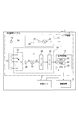
本実施形態の車両警報システム1は、車両に搭載され、図1に示すように、警報装置2と、車速センサ3と、レーダ装置4とを備える。
本実施形態の車両警報システム1は、車両に搭載され、図1に示すように、警報装置2と、車速センサ3と、レーダ装置4とを備える。
警報装置2は、車室内に設置された音声出力装置であり、車両の乗員に対して、警報を発する。
車速センサ3は、車両警報システム1を搭載した車両(以下、自車両という)の走行速度を検出する。
レーダ装置4は、周知の2周波CW(Two-Frequency Continuous Wave)方式を採用しており、送信回路11と、送信アンテナ12と、受信アンテナ13と、受信回路14と、信号処理部15とを備える。
送信回路11は、送信アンテナ12に対して送信信号Ssを供給するものであり、発振器21と増幅器22と分配器23とを備える。発振器21は、ミリ波帯の高周波信号を生成するものであり、短い時間間隔で交互に、第一周波数f1の高周波信号と、第一周波数f1とは僅かに周波数の異なる第二周波数f2の高周波信号とを生成して出力する。増幅器22は、発振器21から出力される上記高周波信号を増幅する。分配器23は、増幅器22の出力信号を送信信号Ssとローカル信号Lとに電力分配する。
送信アンテナ12は、この送信回路11から供給される送信信号Ssに基づいて、送信信号Ssに対応する周波数のレーダ波を照射する。これにより、第一周波数f1のレーダ波と、第二周波数f2のレーダ波とが交互に出力される。
受信アンテナ13は、複数のアンテナ素子を一列に配列して構成されたアレーアンテナである。
受信回路14は、受信スイッチ31と、増幅器32と、ミキサ33と、フィルタ34と、A/D変換器35とを備える。受信スイッチ31は、受信アンテナ13を構成する複数のアンテナ素子の何れか一つを順次選択し、選択されたアンテナ素子からの受信信号Srを増幅器32へ出力する。増幅器32は、受信スイッチ31から入力した受信信号Srを増幅してミキサ33へ出力する。ミキサ33は、増幅器32にて増幅された受信信号Srとローカル信号Lとを混合してビート信号BTを生成する。フィルタ34は、ミキサ33が生成したビート信号BTから不要な信号成分を除去する。A/D変換器35は、フィルタ34から出力されたビート信号BTをサンプリングしてデジタルデータに変換し、このデジタルデータを信号処理部15へ出力する。
信号処理部15は、CPU41、ROM42およびRAM43等を備えた周知のマイクロコンピュータを中心に構成された電子制御装置である。信号処理部15は、ROM42が記憶するプログラムに基づく処理をCPU41が実行することにより、信号解析を行ったり、レーダ装置4の動作の制御を行ったりする。
具体的には、信号処理部15は、送信回路11を制御して、第一周波数f1および第二周波数f2のレーダ波が送信アンテナ12から変調周期Tmで交互に発射されるようにする。また信号処理部15は、受信アンテナ13を構成する複数のアンテナ素子のそれぞれのビート信号BTが受信回路14においてサンプリングされるようにする。そして信号処理部15は、ビート信号BTのサンプリングデータを解析することにより、レーダ波を反射した地点(以下、観測点という)までの距離(以下、観測点距離という)と、観測点との相対速度(以下、観測点相対速度という)と、観測点が存在する方位(以下、観測点方位という)を計測する。
2周波CW方式では、ビート信号BTとして、第1ビート信号および第2ビート信号が生成される。第1ビート信号は、第一周波数f1の受信信号Srと第一周波数f1のローカル信号Lとを混合することにより生成される。同様に第2ビート信号は、第二周波数f2の受信信号Srと第二周波数f2のローカル信号Lとを混合することにより生成される。
そして、第1ビート信号の周波数fb1および第2ビート信号の周波数fb2と、観測点相対速度vとの間には、下式(1)、(2)の関係が成立する。なお、式(1)、(2)において、cは光速である。
fb1=(2v/c)×f1 ・・・(1)
fb2=(2v/c)×f2 ・・・(2)
fb1=(2v/c)×f1 ・・・(1)
fb2=(2v/c)×f2 ・・・(2)
すなわち2周波CW方式では、生成したビート信号の周波数に基づいて、観測点相対速度を計測する。
さらに2周波CW方式では、周知のように、第1ビート信号と第2ビート信号との間の位相差に基づいて、観測点距離を算出する。
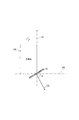
受信アンテナ13は、自車両の後方の左右端にそれぞれ設けられ、図2に示すように、受信アンテナ13の検知範囲の中心軸CAが、自車両100の左右方向HDに対して後方に取付角度φ傾いた方向(左端に位置するものは左側方、右端に位置するものは右側方)を向くように取り付けられている。また検知範囲は、車両の前後方向LDに対して90°の方向を含むように設定されている。本実施例では、中心軸CAを中心として±約90°の範囲をカバーするものを用いている。
このように構成された車両警報システム1において、信号処理部15は、自車両100の付近で走行している車両を検出する走行車両検出処理を実行する。この走行車両検出処理は、信号処理部15の動作中において変調周期Tm毎に実行される処理である。
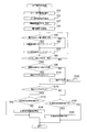
この走行車両検出処理が実行されると、信号処理部15は、図3に示すように、まずステップS10にて、受信回路14から入力したビート信号の周波数解析(本実施形態では、高速フーリエ変換(FFT))を実行して、ビート信号BTのパワースペクトルを求める。このパワースペクトルは、ビート信号の周波数と、各周波数におけるビート信号の強度(本実施形態では、電力)とを表したものである。
なお、ビート信号は実信号である。このため、ビート信号に対してフーリエ変換を行うと、ビート信号の周波数スペクトルは、周波数の絶対値が互いに等しい正の周波数成分と負の周波数成分を有する。
ステップS10では、信号処理部15は、ビート信号に対してIQ検波を行うことによりビート信号の位相を検出し、ビート信号の位相の時間変化に基づいて、IQ平面上におけるビート信号の位相の回転方向を検出する。そしてステップS10では、信号処理部15は、検出した回転方向に基づいて、ビート信号の周波数スペクトルの正の周波数成分と負の周波数成分のうち何れか一方の周波数成分を採用する。これにより、ステップS10では、パワースペクトルは、観測点が自車両に近付く場合にはビート信号の周波数が正となり、観測点が自車両に遠ざかる場合にはビート信号の周波数が負となるように作成される。
このパワースペクトルは、互いに異なる周波数が設定された複数の周波数ビンFB(0)、FB(1)、FB(2)、・・・、FB(m)のそれぞれについて(mは正の整数)、対応する周波数の強度を示す。なお、周波数が小さい順に周波数ビンFB(0)、FB(1)、FB(2)、・・・、FB(m)が設けられている。
ここで、レーダ波を反射した物体が停止物である場合のパワースペクトルと、レーダ波を反射した物体が走行車両である場合のパワースペクトルを説明する。
まず図4に示すように、走行中の自車両のレーダ装置4に向って接近する停止物Bsでレーダ波が反射した場合には、レーダ装置4に向って接近する速度がレーダ装置4により検出される。すなわち、レーダ装置4により検出される相対速度は、レーダ装置4へ向う停止物Bsにおける相対速度の大きさと方向とを示す相対速度ベクトル(図4の相対速度ベクトルVrを参照)について、停止物Bsでレーダ波が反射した反射点Prからレーダ装置4のアンテナの中心Paへ向かう方向の速度成分Vaとなる。
このため、停止物Bsにおける反射点Prの高さがアンテナの中心Paの高さと同じである場合に、速度成分Vaが最大となり、反射点Prの高さとアンテナの中心Paの高さとの差が大きくなるほど速度成分Vaが小さくなる。
したがって、停止物Bsを検出したときのパワースペクトルは、例えば図5に示すように、走行中の自車両と停止物Bsとの相対速度(すなわち、相対速度ベクトルVrの大きさ)に対応するビート信号周波数Fr(以下、相対速度周波数Frという)の付近において、ビート信号周波数が相対速度周波数Frより小さい場合に電力が大きくなる。なお、相対速度周波数Fr付近において電力が大きくなる周波数範囲は、停止物Bsが高くなるほど広くなる。一方、停止物Bsを検出したときのパワースペクトルは、ビート信号周波数がビート信号周波数Frより高くなると、電力が急激に低下する。
次に、走行中の自車両のレーダ装置4に向って接近する走行車両でレーダ波が反射した場合には、走行車両の車輪の速度がレーダ装置4により検出される。
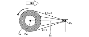
例えば、自車両の前方から接近する走行車両の進行方向が自車両の進行方向と同じである場合には、図6に示すように、走行車両の車輪Bwにおいて、車輪Bwの回転軸Pwとアンテナの中心Paとを結ぶ線Lcより上方の反射点では、レーダ装置4から遠ざかる方向の速度が検出される。また、車輪Bwの回転軸Pwとアンテナの中心Paとを結ぶ線Lcより下方の反射点では、レーダ装置4に向って接近する方向の速度が検出される。
一方、自車両の前方から接近する走行車両の進行方向が自車両の進行方向と逆である場合には、走行車両の車輪Bwにおいて、上記の線Lcより上方の反射点では、レーダ装置4に向って接近する方向の速度が検出され、下方の反射点では、レーダ装置4から遠ざかる方向の速度が検出される(不図示)。
そして、レーダ装置4で検出される速度の大きさは、車輪Bwの回転軸Pwの高さと車輪Bwの反射点の高さとの差が大きくなるほど大きくなる。
また、レーダ装置4で検出される反射レーダ波の強度は、車輪Bwの回転軸Pwの高さと車輪Bwの反射点の高さとの差が大きくなるほど小さくなる。これは、回転軸Pwの高さと反射点の高さとの差が大きくなるほど、アンテナの中心Paと車輪Bwの反射点との距離が長くなるためである。
さらに、車輪Bwは、回転軸Pwを中心として上下対称に形成されているため、反射レーダ波の強度の減衰は上下対称となる。
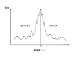
したがって、走行車両の車輪を検出したときのパワースペクトルは、例えば図7に示すように、走行中の自車両と走行車両の車輪との相対速度に対応するビート信号周波数Fr(相対速度周波数Fr)で電力が最大となる。そして、相対速度周波数Frとの差が大きくなるにつれて電力が小さくなる。さらに、相対速度周波数Frを中心として左右対称の電力分布となる。
そしてステップS10の処理が終了すると、図3に示すように、ステップS20にて、信号処理部15は、ビン指示値Nを0に設定する。なおビン指示値Nは、周波数ビンを指示するためのものである。例えば、ビン指示値Nが10に設定されている場合には、ビン指示値Nは、周波数ビンFB(10)を指示する。
さらにステップS30にて、信号処理部15は、閾値超回数Ctを0に設定する。その後ステップS40にて、信号処理部15は、自車両の走行速度を示す自車速情報を車速センサ3から取得し、自車速情報と、ステップS10で作成したパワースペクトルとに基づいて、図8に示すように、電力閾値TJ(0)~電力閾値TJ(m)を設定する。
まず、電力閾値TJ(0)~TJ(i-1)は、第1判定電力pw1に設定される。第1判定電力pw1は、電力PW(N)>電力閾値TJ(N)の関係が成立しないように十分大きい値に設定される。また、周波数ビンFB(i)は、自車両の走行速度と同じ速度で遠ざかる相対速度に対応している。すなわち、周波数ビンFB(i)は、停止物の相対速度に対応している。
電力閾値TJ(i)~TJ(j-1)は、第1判定電力pw1より小さい第2判定電力pw2に設定される(j>i)。なお、第2判定電力pw2は、周波数ビンFB(i)~FB(j-1)の電力値に基づいて、電力PW(N)>電力閾値TJ(N)の関係が成立しないように設定される。
電力閾値TJ(j)は第2判定電力pw2に設定されるとともに、TJ(k-2)は第3判定電力pw3に設定されている(k-2>j)。第3判定電力pw3は、相対速度が0となる物体が自車両の周辺に存在する場合に電力PW(N)>電力閾値TJ(N)の関係が成立し、相対速度が0となる物体が自車両の周辺に存在しない場合に電力PW(N)>電力閾値TJ(N)の関係が成立しないように設定される。
電力閾値TJ(j+1)~TJ(k-3)は、第2判定電力pw2と第3判定電力pw3との間において、ビン指示値Nの増加に伴い、予め設定された傾斜率で単調に増加するように設定されている。
電力閾値TJ(k-1)~TJ(k+1)は、第3判定電力pw3に設定される。
TJ(k+2)は第3判定電力pw3に設定されるとともに、TJ(n)は第4判定電力pw4に設定されている(n>k+2)。第4判定電力pw4は、周波数ビンFB(k)に対応する周波数より十分大きい周波数の周波数ビンの電力値に基づいて、電力PW(N)>電力閾値TJ(N)の関係が成立しないように設定される。
電力閾値TJ(k+3)~TJ(n-1)は、第3判定電力pw3と第4判定電力pw4との間において、ビン指示値Nの増加に伴い、上記傾斜率で単調に減少するように設定されている。
電力閾値TJ(n+1)~TJ(m)は、第4判定電力pw4に設定される。なお第4判定電力pw4は、例えば、下式(3)により算出される。

式(3)は、周波数ビンFB(m-s)~FB(m)までのsビン分の電力PWの平均値を求め、この平均値に一定量のオフセットαを加算したものを第4判定電力pw4とすることを示している。なお、(m-s)は、nより大きい値である。すなわち、FB(m-s)>周波数ビンFB(n)である。
その後ステップS50にて、ビン指示値Nが指示する周波数ビン(以下、周波数ビンFB(N)という)に対応する電力PW(N)が、周波数ビンFB(N)に対して予め設定されている電力閾値TJ(N)より大きいか否かを判断する。
ここで、電力PW(N)が電力閾値TJ(N)以下である場合には(ステップS50:NO)、信号処理部15は、ステップS70に移行する。一方、電力PW(N)が電力閾値TJ(N)より大きい場合には(ステップS50:YES)、信号処理部15は、ステップS60にて、閾値超回数Ctをインクリメント(1加算)し、ステップS70に移行する。
そしてステップS70に移行すると、信号処理部15は、ビン指示値Nをインクリメントし、ステップS80にて、ビン指示値Nが予め設定された判定終了値mより大きいか否かを判断する。ここで、ビン指示値Nが判定終了値m以下である場合には(ステップS80:NO)、信号処理部15は、ステップS50に移行して、上述の処理を繰り返す。一方、ビン指示値Nが判定終了値mより大きい場合には(ステップS80:YES)、信号処理部15は、ステップS90にて、閾値超回数Ctが予め設定された検出判定値より大きいか否かを判断する。
ここで、閾値超回数Ctが検出判定値以下である場合には(ステップS90:NO)、信号処理部15は、ステップS100にて、検出フラグFdをクリアし、ステップS120に移行する。一方、閾値超回数Ctが検出判定値より大きい場合には(ステップS90:YES)、信号処理部15は、ステップS110にて、検出フラグFdをセットし、ステップS120に移行する。
そしてステップS120に移行すると、検出フラグFdがセットされているか否かを判断する。ここで、検出フラグFdがセットされている場合には(ステップS120:YES)、信号処理部15は、ステップS130にて、自車両の付近に走行車両が存在している旨の報知(以下、他車両存在報知という)を警報装置2が実行中であるか否かを判断する。
ここで、警報装置2が他車両存在報知を実行している場合には(ステップS120:YES)、信号処理部15は、走行車両検出処理を一旦終了する。一方、警報装置2が他車両存在報知を実行していない場合には(ステップS120:NO)、信号処理部15は、ステップS130にて、警報装置2に他車両存在報知を開始させ、走行車両検出処理を一旦終了する。
またステップS120にて、検出フラグFdがセットされていない場合には(ステップS120:NO)、信号処理部15は、ステップS150にて、他車両存在報知を警報装置2が実行中であるか否かを判断する。ここで、警報装置2が他車両存在報知を実行していない場合には(ステップS150:NO)、信号処理部15は、走行車両検出処理を一旦終了する。一方、警報装置2が他車両存在報知を実行している場合には(ステップS150:YES)、信号処理部15は、ステップS160にて、警報装置2に他車両存在報知を終了させ、走行車両検出処理を一旦終了する。
このように構成された車両警報システム1のレーダ装置4は、車両の前後方向に対して90°の方向を検知範囲に含むように車両に取り付けられ、レーダ波を送受信することにより、検知範囲内に存在するレーダ波を反射した観測点との相対速度を検出する。
そしてレーダ装置4は、複数の観測点について、ビート信号の周波数と、ビート信号の強度との対応関係を示すパワースペクトルを作成する(ステップS10)。
さらにレーダ装置4は、パワースペクトルにおいて、第1検出条件、第2検出条件および第3検出条件の全てが成立したときに、走行車両を検出したと判断する(ステップS20~S100)。第1検出条件は、相対速度周波数Frからビート信号の周波数が大きくなるほどビート信号の強度が小さくなることである。第2検出条件は、相対速度周波数Frからビート信号の周波数が小さくなるほどビート信号の強度が小さくなることである。第3検出条件は、ビート信号の強度の分布が相対速度周波数Frを中心として対称であることである。
このように構成されたレーダ装置4では、第1検出条件、第2検出条件および第3検出条件に基づいて、回転している車輪を検出している。そしてレーダ装置4は、回転している車輪を備えている物体は、走行中の車両であると判断することにより、走行車両を検出したと判断する。
このようにレーダ装置4によれば、回転している車輪を上記パワースペクトルに基づいて検出することができるため、検出物体との相対速度が0である場合であっても、検出物体が走行中であるか否かを判断することができる。
またレーダ装置4は、2周波CW方式によりレーダ波を送受信することにより観測点相対速度を検出している。そしてレーダ装置4は、ビート信号の周波数と、ビート信号の強度との対応関係を示すパワースペクトルを作成することにより、走行車両を検出する。これは、2周波CW方式において、生成したビート信号の周波数と観測点相対速度との間に比例関係が成立しているとともに、生成したビート信号の強度と、観測点で反射したレーダ波の反射強度との間に比例関係が成立しているからである。
このようにレーダ装置4は、走行車両を検出するために、2周波CW方式で一般的に作成されるパワースペクトルを利用することができるため、走行車両を検出するための演算処理負荷を低減することができる。
またレーダ装置4は、相対速度周波数Fr(周波数ビンFB(k))からビート信号の周波数が大きくなるほど予め設定された傾斜率で単調に減少するとともに、相対速度周波数Frからビート信号の周波数が小さくほど上記傾斜率で単調に減少するように予め設定された電力閾値TJ(j+1)~TJ(k-3)、TJ(k+3)~TJ(n-1)と、ビート信号の強度とを比較することにより、走行車両を検出したか否かを判断する。
これにより、電力閾値TJとビート信号の強度とを比較するという簡便な方法で走行車両を検出することができ、走行車両を検出するための演算処理負荷を低減することができる。
また車両警報システム1では、警報装置2は、走行車両を検出したレーダ装置4が判断した場合に、車両の乗員に対して、他車両存在報知を実行する。これにより、自車両の付近に走行車両が存在している場合に、その旨を車両の乗員に知らせることができる。
以上説明した実施形態において、レーダ装置4は本発明における車載レーダ装置、信号処理部15によるステップS10の処理は本発明における強度分布作成手段、信号処理部15によるステップS20~S100の処理は本発明における走行車両検出手段、警報装置2は本発明における報知装置、車両警報システム1は本発明における報知システムである。
以上、本発明の一実施形態について説明したが、本発明は上記実施形態に限定されるものではなく、本発明の技術的範囲に属する限り種々の形態を採ることができる。
例えば上記実施形態では、2周波CW方式を採用して観測点との相対速度を検出するものを示したが、検出方式はこれに限定されるものではなく、例えばFMCW(Frequency Modulated Continuous Wave)方式を採用して相対速度を検出するようにしてもよい。
また上記実施形態では、受信アンテナ13を自車両の後方に向けて取り付けるものを示したが、受信アンテナ13を自車両の前方に向けて取り付けた場合でも本発明を適用可能である。
また上記実施形態では、相対速度周波数Frを特に限定していないものを示した。しかし、相対速度周波数Frを、0km/hの観測点相対速度に対応する値(すなわち、相対速度周波数Fr=0)に固定するようにしてもよい。これにより、観測点相対速度が0であることに起因して、観測点相対速度に基づいて検出物体が走行中であるか否かを判断することができない状況下においても、検出物体が走行中であるか否かを判断することができる。
また上記実施形態では、上記傾斜率を固定しているものを示した。しかし、車両サイズ(トラック、普通車、軽自動車および二輪車等)に応じて異なる複数の傾斜率を予め設定しておき、作成されたパワースペクトルにおける相対速度周波数Fr付近のピークの傾きに最も近い傾斜率を選択するようにしてもよい。
また上記実施形態では、S10でパワースペクトルを作成する毎に、作成したパワースペクトルに基づいて、判定電力pw1~pw4を算出するものを示した。しかし、パワースペクトルの形状は、短時間で大きく変動しないため、パワースペクトルを複数回作成する毎に、判定電力pw1~pw4を算出するようにしてもよい。
また上記実施形態では、パワースペクトルの全周波数範囲について、電力閾値TJとビート信号の強度とを比較するものを示した。しかし、相対速度周波数Fr付近の予め設定された周波数範囲において電力閾値TJとビート信号の強度とを比較するようにしてもよい。
また、上記実施形態における1つの構成要素が有する機能を複数の構成要素として分散させたり、複数の構成要素が有する機能を1つの構成要素に統合させたりしてもよい。また、上記実施形態の構成の少なくとも一部を、同様の機能を有する公知の構成に置き換えてもよい。また、上記実施形態の構成の一部を省略してもよい。また、上記実施形態の構成の少なくとも一部を、他の上記実施形態の構成に対して付加または置換してもよい。なお、特許請求の範囲に記載した文言のみによって特定される技術思想に含まれるあらゆる態様が本発明の実施形態である。
1…車両警報システム、2…警報装置、4…レーダ装置
Claims (6)
- 車両の前後方向に対して90°の方向を検知範囲に含むように前記車両に取り付けられ、レーダ波を送受信することにより、前記検知範囲内に存在する前記レーダ波を反射した観測点との相対速度である観測点相対速度を検出する車載レーダ装置(4)であって、
複数の前記観測点について、前記観測点相対速度に関連する相対速度パラメータと、前記観測点で反射した前記レーダ波の反射強度に関連する反射強度パラメータとの対応関係を示す強度分布を作成する強度分布作成手段(S10)と、
前記強度分布において、前記反射強度のピークに対応する前記相対速度パラメータである中心相対速度パラメータから前記相対速度パラメータが大きくなるほど前記反射強度パラメータが小さくなり、且つ、前記中心相対速度パラメータから前記相対速度パラメータが小さくなるほど前記反射強度パラメータが小さくなり、且つ、前記反射強度パラメータの分布が前記中心相対速度パラメータを中心として対称である場合に、走行車両を検出したと判断する走行車両検出手段(S20~S100)とを備えることを特徴とする車載レーダ装置。 - 当該車載レーダ装置は、2周波CW方式により前記レーダ波を送受信することにより前記観測点相対速度を検出し、
前記相対速度パラメータは、当該車載レーダ装置において2周波CW方式に基づいて生成されるビート信号の周波数であり、
前記反射強度パラメータは、前記ビート信号の強度であることを特徴とする請求項1に記載の車載レーダ装置。 - 前記中心相対速度パラメータは、0km/hの前記観測点相対速度に対応する値であることを特徴とする請求項1または請求項2に記載の車載レーダ装置。
- 前記走行車両検出手段は、前記中心相対速度パラメータから前記相対速度パラメータが大きくなるほど予め設定された傾斜率で単調に減少するとともに、前記中心相対速度パラメータから前記相対速度パラメータが小さくほど前記傾斜率で単調に減少するように予め設定された走行車両判定値と、前記反射強度パラメータとを比較することにより、前記走行車両を検出したか否かを判断することを特徴とする請求項1~請求項3の何れか1項に記載の車載レーダ装置。
- 請求項1~請求項4の何れか1項に記載の車載レーダ装置と、
前記走行車両を検出したと前記走行車両検出手段が判断した場合に、その旨を前記車両の乗員に報知する報知装置(2)とを備えることを特徴とする報知システム(1)。 - 車両の前後方向に対して90°の方向を検知範囲に含むように前記車両に取り付けられ、レーダ波を送受信することにより、前記検知範囲内に存在する前記レーダ波を反射した観測点との相対速度である観測点相対速度を検出する車載レーダ装置の走行車両検出方法であって、
前記車載レーダ装置の強度分布作成手段により、複数の前記観測点について、前記観測点相対速度に関連する相対速度パラメータと、前記観測点で反射した前記レーダ波の反射強度に関連する反射強度パラメータとの対応関係を示す強度分布を作成し、
前記車載レーダ装置の走行車両検出手段により、前記強度分布において、前記反射強度のピークに対応する前記相対速度パラメータである中心相対速度パラメータから前記相対速度パラメータが大きくなるほど前記反射強度パラメータが小さくなり、且つ、前記中心相対速度パラメータから前記相対速度パラメータが小さくなるほど前記反射強度パラメータが小さくなり、且つ、前記反射強度パラメータの分布が前記中心相対速度パラメータを中心として対称である場合に、走行車両を検出したと判断することを特徴とする車載レーダ装置の走行車両検出方法。
Priority Applications (3)
| Application Number | Priority Date | Filing Date | Title |
|---|---|---|---|
| CN201580038476.7A CN106537177B (zh) | 2014-07-16 | 2015-07-13 | 车载雷达装置以及报告系统 |
| DE112015003285.1T DE112015003285B4 (de) | 2014-07-16 | 2015-07-13 | An einem fahrzeug montierte radarvorrichtung und benachrichtigungssystem |
| US15/325,884 US10746853B2 (en) | 2014-07-16 | 2015-07-13 | On-board radar apparatus and notification system |
Applications Claiming Priority (2)
| Application Number | Priority Date | Filing Date | Title |
|---|---|---|---|
| JP2014145980A JP6375744B2 (ja) | 2014-07-16 | 2014-07-16 | 車載レーダ装置および報知システム |
| JP2014-145980 | 2014-07-16 |
Publications (1)
| Publication Number | Publication Date |
|---|---|
| WO2016009999A1 true WO2016009999A1 (ja) | 2016-01-21 |
Family
ID=55078491
Family Applications (1)
| Application Number | Title | Priority Date | Filing Date |
|---|---|---|---|
| PCT/JP2015/070068 Ceased WO2016009999A1 (ja) | 2014-07-16 | 2015-07-13 | 車載レーダ装置および報知システム |
Country Status (5)
| Country | Link |
|---|---|
| US (1) | US10746853B2 (ja) |
| JP (1) | JP6375744B2 (ja) |
| CN (1) | CN106537177B (ja) |
| DE (1) | DE112015003285B4 (ja) |
| WO (1) | WO2016009999A1 (ja) |
Families Citing this family (10)
| Publication number | Priority date | Publication date | Assignee | Title |
|---|---|---|---|---|
| JP6392152B2 (ja) * | 2015-03-24 | 2018-09-19 | パナソニック株式会社 | レーダ装置および走行車両検知方法 |
| JP6560165B2 (ja) * | 2016-07-08 | 2019-08-14 | 株式会社Soken | レーダ装置 |
| KR102314336B1 (ko) * | 2017-09-14 | 2021-10-19 | 주식회사 만도모빌리티솔루션즈 | 차량용 레이더 장치 및 그의 각도 추정 방법 |
| JP6989766B2 (ja) * | 2017-09-29 | 2022-01-12 | ミツミ電機株式会社 | レーダー装置及び物標検出方法 |
| CN110609285B (zh) * | 2018-06-14 | 2023-07-14 | 安波福电子(苏州)有限公司 | 用于车辆自动制动的控制装置及控制方法 |
| JP7173785B2 (ja) * | 2018-08-09 | 2022-11-16 | 株式会社デンソーテン | 物標検出装置および物標検出方法 |
| CN110088643B (zh) * | 2018-08-31 | 2021-12-07 | 深圳迈睿智能科技有限公司 | 人体存在探测器及其人体存在探测方法 |
| JP7354765B2 (ja) * | 2019-10-25 | 2023-10-03 | 株式会社デンソー | 移動体警報装置 |
| CN113049846B (zh) * | 2019-12-27 | 2024-10-01 | 伟摩有限责任公司 | 用于测量拖车车轮转速的系统和方法 |
| CN111409584A (zh) * | 2020-02-27 | 2020-07-14 | 广汽蔚来新能源汽车科技有限公司 | 行人保护方法、装置、计算机设备和存储介质 |
Citations (7)
| Publication number | Priority date | Publication date | Assignee | Title |
|---|---|---|---|---|
| JPH05232214A (ja) * | 1992-02-21 | 1993-09-07 | Fujitsu Ten Ltd | Fm−cwレーダ装置 |
| JPH07234277A (ja) * | 1994-02-24 | 1995-09-05 | Isuzu Motors Ltd | 障害物検知装置 |
| JP2002323559A (ja) * | 2001-04-25 | 2002-11-08 | Nec Corp | レーダ用信号処理装置 |
| JP2007292643A (ja) * | 2006-04-26 | 2007-11-08 | Alpine Electronics Inc | 周辺物体識別装置 |
| JP2010043960A (ja) * | 2008-08-13 | 2010-02-25 | Nissan Motor Co Ltd | 車両移動状況検出装置および車両移動状況検出方法 |
| JP2013257249A (ja) * | 2012-06-13 | 2013-12-26 | Toyota Motor Corp | 物体検出装置 |
| JP2015034705A (ja) * | 2013-08-07 | 2015-02-19 | トヨタ自動車株式会社 | 移動物体速度検出装置 |
Family Cites Families (11)
| Publication number | Priority date | Publication date | Assignee | Title |
|---|---|---|---|---|
| JP3734721B2 (ja) * | 2001-05-18 | 2006-01-11 | 三菱電機株式会社 | レーダ装置、目標類別方法および目標類別プログラム |
| DE102005024716B4 (de) * | 2005-05-30 | 2023-09-21 | Robert Bosch Gmbh | Verfahren und Vorrichtung zur Erkennung und Klassifizierung von Objekten |
| JP2009103565A (ja) | 2007-10-23 | 2009-05-14 | Omron Corp | 測定装置および方法 |
| JP4977042B2 (ja) * | 2008-01-10 | 2012-07-18 | 株式会社東芝 | レーダ装置および目標検出方法 |
| JP2010038706A (ja) | 2008-08-05 | 2010-02-18 | Fujitsu Ten Ltd | 信号処理装置、及びレーダ装置 |
| DE102008037233B4 (de) * | 2008-08-09 | 2010-06-17 | Rtb Gmbh & Co. Kg | Fahrzeugklassifikator mit einer Einrichtung zur Erkennung eines zollenden Rades |
| JP5444941B2 (ja) | 2009-08-25 | 2014-03-19 | トヨタ自動車株式会社 | 物体検出装置 |
| JP5256223B2 (ja) * | 2010-01-27 | 2013-08-07 | 富士通テン株式会社 | レーダシステム、及び方位検出方法 |
| DE102011082950B4 (de) * | 2011-09-19 | 2013-08-01 | Ford Global Technologies, Llc | Verfahren zur Durchführung eines automatischen Bremsvorgangs |
| JP6009775B2 (ja) * | 2012-02-13 | 2016-10-19 | 株式会社デンソー | レーダ装置 |
| DE102012025064A1 (de) * | 2012-12-19 | 2014-06-26 | Valeo Schalter Und Sensoren Gmbh | Verfahren zum Aufrechterhalten eines Warnsignals in einem Kraftfahrzeug aufgrund der Präsenz eines Zielobjekts in einem Warnbereich, insbesondere einem Totwinkelbereich, entsprechendes Fahrerassistenzsystem und Kraftfahrzeug |
-
2014
- 2014-07-16 JP JP2014145980A patent/JP6375744B2/ja active Active
-
2015
- 2015-07-13 CN CN201580038476.7A patent/CN106537177B/zh active Active
- 2015-07-13 WO PCT/JP2015/070068 patent/WO2016009999A1/ja not_active Ceased
- 2015-07-13 DE DE112015003285.1T patent/DE112015003285B4/de active Active
- 2015-07-13 US US15/325,884 patent/US10746853B2/en active Active
Patent Citations (7)
| Publication number | Priority date | Publication date | Assignee | Title |
|---|---|---|---|---|
| JPH05232214A (ja) * | 1992-02-21 | 1993-09-07 | Fujitsu Ten Ltd | Fm−cwレーダ装置 |
| JPH07234277A (ja) * | 1994-02-24 | 1995-09-05 | Isuzu Motors Ltd | 障害物検知装置 |
| JP2002323559A (ja) * | 2001-04-25 | 2002-11-08 | Nec Corp | レーダ用信号処理装置 |
| JP2007292643A (ja) * | 2006-04-26 | 2007-11-08 | Alpine Electronics Inc | 周辺物体識別装置 |
| JP2010043960A (ja) * | 2008-08-13 | 2010-02-25 | Nissan Motor Co Ltd | 車両移動状況検出装置および車両移動状況検出方法 |
| JP2013257249A (ja) * | 2012-06-13 | 2013-12-26 | Toyota Motor Corp | 物体検出装置 |
| JP2015034705A (ja) * | 2013-08-07 | 2015-02-19 | トヨタ自動車株式会社 | 移動物体速度検出装置 |
Also Published As
| Publication number | Publication date |
|---|---|
| JP2016023948A (ja) | 2016-02-08 |
| CN106537177B (zh) | 2019-05-07 |
| US10746853B2 (en) | 2020-08-18 |
| DE112015003285B4 (de) | 2023-04-20 |
| DE112015003285T5 (de) | 2017-04-06 |
| JP6375744B2 (ja) | 2018-08-22 |
| US20170176585A1 (en) | 2017-06-22 |
| CN106537177A (zh) | 2017-03-22 |
Similar Documents
| Publication | Publication Date | Title |
|---|---|---|
| JP6375744B2 (ja) | 車載レーダ装置および報知システム | |
| JP6552167B2 (ja) | 車載レーダ装置および報知システム | |
| JP6560165B2 (ja) | レーダ装置 | |
| JP6394138B2 (ja) | 車載レーダ装置および報知システム | |
| JP4462060B2 (ja) | Fmcwレーダ装置 | |
| US9869761B2 (en) | Radar apparatus | |
| US8638254B2 (en) | Signal processing device, radar device, vehicle control system, signal processing method, and computer-readable medium | |
| US10371815B2 (en) | Radar module, transport apparatus, and object detection method | |
| US9874634B1 (en) | Radar apparatus | |
| JP2018059813A (ja) | レーダ装置および物標検出方法 | |
| JP6127554B2 (ja) | レーダ装置 | |
| US20130088379A1 (en) | Radar system and detection method | |
| WO2014104298A1 (ja) | 車載レーダ装置 | |
| CN104459684A (zh) | 用于检测雷达波的爬行的设备 | |
| JP6858093B2 (ja) | レーダ装置および物標検出方法 | |
| JPH08211145A (ja) | 車載用レーダ装置 | |
| JP2011047806A (ja) | 信号処理装置、レーダ装置、車両制御システム、信号処理方法、および、プログラム | |
| JP2006047052A (ja) | ミリ波レーダ装置 | |
| JP2022046300A (ja) | 移動速度の検出装置および検出方法 | |
| WO2011136281A1 (ja) | 車載用レーダ装置及び車載用レーダシステム | |
| JP2001183451A (ja) | レーダ装置 | |
| JP2007232499A (ja) | 車載用レーダ装置 |
Legal Events
| Date | Code | Title | Description |
|---|---|---|---|
| 121 | Ep: the epo has been informed by wipo that ep was designated in this application |
Ref document number: 15822207 Country of ref document: EP Kind code of ref document: A1 |
|
| WWE | Wipo information: entry into national phase |
Ref document number: 15325884 Country of ref document: US |
|
| WWE | Wipo information: entry into national phase |
Ref document number: 112015003285 Country of ref document: DE |
|
| 122 | Ep: pct application non-entry in european phase |
Ref document number: 15822207 Country of ref document: EP Kind code of ref document: A1 |