WO2016009885A1 - 加飾同時成形システム及び加飾同時成形品の製造方法 - Google Patents
加飾同時成形システム及び加飾同時成形品の製造方法 Download PDFInfo
- Publication number
- WO2016009885A1 WO2016009885A1 PCT/JP2015/069482 JP2015069482W WO2016009885A1 WO 2016009885 A1 WO2016009885 A1 WO 2016009885A1 JP 2015069482 W JP2015069482 W JP 2015069482W WO 2016009885 A1 WO2016009885 A1 WO 2016009885A1
- Authority
- WO
- WIPO (PCT)
- Prior art keywords
- winding
- decorative sheet
- feeding
- side roller
- mold
- Prior art date
- Legal status (The legal status is an assumption and is not a legal conclusion. Google has not performed a legal analysis and makes no representation as to the accuracy of the status listed.)
- Ceased
Links
Images





Classifications
-
- B—PERFORMING OPERATIONS; TRANSPORTING
- B29—WORKING OF PLASTICS; WORKING OF SUBSTANCES IN A PLASTIC STATE IN GENERAL
- B29C—SHAPING OR JOINING OF PLASTICS; SHAPING OF MATERIAL IN A PLASTIC STATE, NOT OTHERWISE PROVIDED FOR; AFTER-TREATMENT OF THE SHAPED PRODUCTS, e.g. REPAIRING
- B29C45/00—Injection moulding, i.e. forcing the required volume of moulding material through a nozzle into a closed mould; Apparatus therefor
- B29C45/14—Injection moulding, i.e. forcing the required volume of moulding material through a nozzle into a closed mould; Apparatus therefor incorporating preformed parts or layers, e.g. injection moulding around inserts or for coating articles
-
- B—PERFORMING OPERATIONS; TRANSPORTING
- B29—WORKING OF PLASTICS; WORKING OF SUBSTANCES IN A PLASTIC STATE IN GENERAL
- B29C—SHAPING OR JOINING OF PLASTICS; SHAPING OF MATERIAL IN A PLASTIC STATE, NOT OTHERWISE PROVIDED FOR; AFTER-TREATMENT OF THE SHAPED PRODUCTS, e.g. REPAIRING
- B29C45/00—Injection moulding, i.e. forcing the required volume of moulding material through a nozzle into a closed mould; Apparatus therefor
- B29C45/14—Injection moulding, i.e. forcing the required volume of moulding material through a nozzle into a closed mould; Apparatus therefor incorporating preformed parts or layers, e.g. injection moulding around inserts or for coating articles
- B29C45/14688—Coating articles provided with a decoration
-
- B—PERFORMING OPERATIONS; TRANSPORTING
- B29—WORKING OF PLASTICS; WORKING OF SUBSTANCES IN A PLASTIC STATE IN GENERAL
- B29C—SHAPING OR JOINING OF PLASTICS; SHAPING OF MATERIAL IN A PLASTIC STATE, NOT OTHERWISE PROVIDED FOR; AFTER-TREATMENT OF THE SHAPED PRODUCTS, e.g. REPAIRING
- B29C45/00—Injection moulding, i.e. forcing the required volume of moulding material through a nozzle into a closed mould; Apparatus therefor
- B29C45/14—Injection moulding, i.e. forcing the required volume of moulding material through a nozzle into a closed mould; Apparatus therefor incorporating preformed parts or layers, e.g. injection moulding around inserts or for coating articles
- B29C45/14065—Positioning or centering articles in the mould
-
- B—PERFORMING OPERATIONS; TRANSPORTING
- B29—WORKING OF PLASTICS; WORKING OF SUBSTANCES IN A PLASTIC STATE IN GENERAL
- B29C—SHAPING OR JOINING OF PLASTICS; SHAPING OF MATERIAL IN A PLASTIC STATE, NOT OTHERWISE PROVIDED FOR; AFTER-TREATMENT OF THE SHAPED PRODUCTS, e.g. REPAIRING
- B29C45/00—Injection moulding, i.e. forcing the required volume of moulding material through a nozzle into a closed mould; Apparatus therefor
- B29C45/17—Component parts, details or accessories; Auxiliary operations
- B29C45/76—Measuring, controlling or regulating
-
- B—PERFORMING OPERATIONS; TRANSPORTING
- B29—WORKING OF PLASTICS; WORKING OF SUBSTANCES IN A PLASTIC STATE IN GENERAL
- B29C—SHAPING OR JOINING OF PLASTICS; SHAPING OF MATERIAL IN A PLASTIC STATE, NOT OTHERWISE PROVIDED FOR; AFTER-TREATMENT OF THE SHAPED PRODUCTS, e.g. REPAIRING
- B29C45/00—Injection moulding, i.e. forcing the required volume of moulding material through a nozzle into a closed mould; Apparatus therefor
- B29C45/17—Component parts, details or accessories; Auxiliary operations
- B29C45/76—Measuring, controlling or regulating
- B29C45/80—Measuring, controlling or regulating of relative position of mould parts
-
- B—PERFORMING OPERATIONS; TRANSPORTING
- B29—WORKING OF PLASTICS; WORKING OF SUBSTANCES IN A PLASTIC STATE IN GENERAL
- B29C—SHAPING OR JOINING OF PLASTICS; SHAPING OF MATERIAL IN A PLASTIC STATE, NOT OTHERWISE PROVIDED FOR; AFTER-TREATMENT OF THE SHAPED PRODUCTS, e.g. REPAIRING
- B29C45/00—Injection moulding, i.e. forcing the required volume of moulding material through a nozzle into a closed mould; Apparatus therefor
- B29C45/14—Injection moulding, i.e. forcing the required volume of moulding material through a nozzle into a closed mould; Apparatus therefor incorporating preformed parts or layers, e.g. injection moulding around inserts or for coating articles
- B29C45/14688—Coating articles provided with a decoration
- B29C2045/14696—Coating articles provided with a decoration transparent decorated inserts
-
- B—PERFORMING OPERATIONS; TRANSPORTING
- B29—WORKING OF PLASTICS; WORKING OF SUBSTANCES IN A PLASTIC STATE IN GENERAL
- B29C—SHAPING OR JOINING OF PLASTICS; SHAPING OF MATERIAL IN A PLASTIC STATE, NOT OTHERWISE PROVIDED FOR; AFTER-TREATMENT OF THE SHAPED PRODUCTS, e.g. REPAIRING
- B29C2945/00—Indexing scheme relating to injection moulding, i.e. forcing the required volume of moulding material through a nozzle into a closed mould
- B29C2945/76—Measuring, controlling or regulating
- B29C2945/76003—Measured parameter
- B29C2945/76083—Position
- B29C2945/76096—Distance
-
- B—PERFORMING OPERATIONS; TRANSPORTING
- B29—WORKING OF PLASTICS; WORKING OF SUBSTANCES IN A PLASTIC STATE IN GENERAL
- B29C—SHAPING OR JOINING OF PLASTICS; SHAPING OF MATERIAL IN A PLASTIC STATE, NOT OTHERWISE PROVIDED FOR; AFTER-TREATMENT OF THE SHAPED PRODUCTS, e.g. REPAIRING
- B29C2945/00—Indexing scheme relating to injection moulding, i.e. forcing the required volume of moulding material through a nozzle into a closed mould
- B29C2945/76—Measuring, controlling or regulating
- B29C2945/76177—Location of measurement
- B29C2945/76254—Mould
-
- B—PERFORMING OPERATIONS; TRANSPORTING
- B29—WORKING OF PLASTICS; WORKING OF SUBSTANCES IN A PLASTIC STATE IN GENERAL
- B29C—SHAPING OR JOINING OF PLASTICS; SHAPING OF MATERIAL IN A PLASTIC STATE, NOT OTHERWISE PROVIDED FOR; AFTER-TREATMENT OF THE SHAPED PRODUCTS, e.g. REPAIRING
- B29C2945/00—Indexing scheme relating to injection moulding, i.e. forcing the required volume of moulding material through a nozzle into a closed mould
- B29C2945/76—Measuring, controlling or regulating
- B29C2945/76655—Location of control
- B29C2945/76772—Inserts
Definitions
- the present invention relates to a decorative simultaneous molding system that performs decoration simultaneously with molding of a resin molded product using a decorative sheet, and a method for manufacturing the decorated simultaneous molded product.
- a transfer molding method for transferring a pattern using a decorative sheet at the time of molding a resin molded product is conventionally known as disclosed in Patent Document 1, for example.
- the decorative sheet feeding device and the winding device are provided in the alignment of the decorative sheet and the mold in the transfer molding method described in Patent Document 1, after the decorative sheet is conveyed to a predetermined position in the feeding direction.
- the decorative sheet feeding device and the winding device are provided.
- the positional deviation in the width direction and the longitudinal direction of the decorative sheet become the mold.
- Positioning is performed by correcting the tilted state.
- An object of the present invention is to provide a decorative simultaneous molding system and a method for manufacturing a decorative simultaneous molded product that can suppress the occurrence of misalignment in the case of simultaneous decorative decoration that requires fine alignment.
- the decorative simultaneous molding system is for feeding a decorating sheet having a sending-out roller for feeding a decorating sheet on which a design for decorating is formed, and for winding up the decorating sheet.
- a winding device having a winding roller, and a mold in which a decorative sheet is arranged between the feeding device and the winding device, and the decorative sheet is arranged in the mold
- an injection molding device for performing molding a symbol position detection device for detecting the symbol position of the decorative sheet placed in the injection molding device, and sending according to the detection result of the symbol position detection device
- the sliding side roller and the winding side roller are moved relative to the mold in the in-plane direction of the parting surface of the mold and perpendicular to the feeding direction of the decorative sheet.
- a first moving device for aligning the In accordance with the detection result of the position detection device the mold is arranged so that the feeding direction of the decorative sheet in the in-plane direction of the parting surface of the mold is orthogonal to the axial direction of both the feeding side roller and the winding side roller.
- a second moving device for rotating and moving the feeding-side roller and the winding-side roller to align the symbols.
- the mold when the angle in the feeding direction of the decorative sheet is deviated with respect to the mold, the mold is moved by the second moving device according to the detection result of the symbol position detecting device. Since the feed roller and take-up roller are rotated relative to the mold to align the pattern, the feeding direction of the decorative sheet is fed in the in-plane direction of the parting surface of the mold. It can be made orthogonal to the axial direction of both the side roller and the winding side roller. Thereby, the twist of the decorating sheet
- the second moving device has a first rotation shaft that connects the feeding device and the injection molding device, and a second rotation shaft that connects the injection molding device and the winding device, and the second rotation device is centered on the first rotation shaft.
- the feed device is rotated clockwise and the winding device is rotated clockwise around the second rotation axis, or the feed device is rotated counterclockwise around the first rotation axis.
- the feeding direction of the decorative sheet is configured to be orthogonal to the axial direction of both the feeding side roller and the winding side roller. Also good.
- the first rotating shaft and the second rotating shaft are provided on both sides of the injection molding device, and the feeding device and the winding device are respectively set around the first rotating shaft and the second rotating shaft. Since the take-up device only needs to be rotated in the same direction to the same extent, the configuration is simplified and the system can be provided at low cost.
- the second moving device uses a rotation center set on the mold as an axis, and maintains a relative positional relationship between the feed side roller and the take-up side roller, and the feed side roller and the feed side roller relative to the mold.
- You may comprise so that a winding side roller may be rotated together and a feeding direction of a decorating sheet may be sent out and orthogonally crossed with the axial direction of both a side roller and a winding side roller.
- the relative positional relationship between the feeding-side roller and the winding-side roller is maintained even after the rotational movement, so that the decorative sheet feeding direction and the feeding direction are fed.
- the symbol position detecting device includes a first positioning sensor disposed substantially at the center of the decorative sheet in the feeding direction with respect to the mold, and a second positioning sensor separated from the first positioning sensor in the decorative sheet feeding direction.
- the first moving device moves until a positioning mark extending in the feeding direction of the decorative sheet is detected by the first positioning sensor, and the second moving device detects the positioning mark by the second positioning sensor.
- the feeding direction of the decorative sheet may be rotationally moved until it is done. In the decorative simultaneous molding system configured as described above, even if the feeding direction of the decorative sheet is rotated by the second moving device, the shift due to the rotational movement of the first positioning sensor can be reduced, and the alignment by the second positioning sensor is performed. The trouble of aligning the first positioning sensor later can be saved.
- the manufacturing method of the decorative simultaneous molded product according to an aspect of the present invention is provided between a feeding-side roller of a feeding device that feeds a decorative sheet and a winding-side roller of a winding device that winds the decorative sheet.
- the design of the decorative sheet using the design position detecting device at a predetermined position of the mold, and a conveying step for conveying the decorative sheet to arrange the decorative sheet on the mold of the injection molding device arranged
- a conveyance position adjustment step for adjusting the conveyance position, and a feeding device and a winding in the width direction that is in-plane direction of the parting surface of the mold and orthogonal to the feeding direction of the decorative sheet To move the device relative to each other to align the symbols
- the width direction adjustment process of the mold and the mold so that the feeding direction of the decorative sheet in the in-plane
- the feeding direction of the decorative sheet is set in the in-plane direction of the parting surface of the mold. It can be orthogonal to the axial direction of both the delivery side roller and the take-up side roller.
- the second rotating shaft that connects the injection molding device and the winding device is rotated while the sending device is rotated clockwise around the first rotating shaft that connects the feeding device and the injection molding device.
- the first rotating shaft and the second rotating shaft are provided on both sides of the injection molding apparatus, and the first rotating shaft and the second rotating shaft are used as the axes, respectively. Since the device and the winding device need only be rotated in the same direction to the same extent, the angle adjustment is simplified.
- the angle adjustment process uses the rotation center set on the mold as an axis, and maintains the relative positional relationship between the feed-side roller and the take-up roller, and the feed-side roller and the winding roll relatively to the mold. It may include a step of rotating the take-up roller together to feed the decorating sheet in the feeding direction so as to be orthogonal to the axial direction of both the take-up side roller and the take-up side roller.
- the relative positional relationship between the feeding-side roller and the winding-side roller is maintained even after the rotational movement, so the feeding direction of the decorative sheet And twisting of the decorative sheet caused by the fact that the axial directions of the feeding side roller and the winding side roller are not perpendicular to each other can be completely eliminated.
- simultaneous molding that requires fine alignment, it is possible to prevent the occurrence of misalignment caused by twisting of the decorative sheet.
- the alignment step is a direction that intersects the feeding direction until a positioning mark extending in the feeding direction of the decorative sheet is detected by the first positioning sensor that is disposed at the approximate center of the mold in the feeding direction of the decorative sheet.
- a second step of rotating the decorative sheet feeding direction until a positioning mark is detected by the second positioning sensor separated from the first positioning sensor in the decorative sheet feeding direction. May be included.
- the typical top view of the decoration simultaneous molding system concerning a 1st embodiment of the present invention.
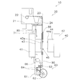
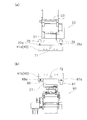
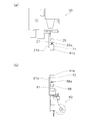
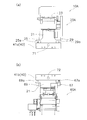
- the typical side view of the decorating simultaneous molding system of FIG. The typical side view of the decorating simultaneous molding system of FIG. (A) The top view of the sending-out apparatus of the decorating simultaneous molding system of FIG. 1, (b) The top view of the winding apparatus of the decorating simultaneous forming system of FIG. (A) The side view of the delivery apparatus of the decorating simultaneous molding system of FIG. 1, (b) The side view of the winding apparatus of the decorating simultaneous forming system of FIG.
- FIG. 1 is a schematic plan view of the simultaneous decoration system
- FIGS. 2 and 3 are schematic side views of the simultaneous decoration system.
- the decorative simultaneous molding system 10 winds the decorative sheet 90, the feeding device 20 that sends the decorative sheet 90, the injection molding device 40 that decorates the molded product simultaneously with the injection molding using the decorative sheet 90, and the decorative sheet 90.
- a winding device 60, and a control device 80 for controlling the feeding device 20, the injection molding device 40, and the winding device 60 are provided.
- the feeding device 20 and the winding device 60 constitute a foil feeding device.
- the foil feeding device is usually attached to the movable side of the injection molding device 40.
- the foil feeding device may be attached to the fixed side of the injection molding device 40 depending on the mold specifications.
- the injection molding apparatus 40 includes a movable mold 43 attached on the movable platen 41 and a fixed mold 44 attached to the fixed platen 42.
- the fixed platen 42 and the fixed mold 44 are not shown.
- a cavity 43a is formed in the movable mold 43, and a core 44a corresponding to the cavity 43a is formed in the fixed mold 44.
- the delivery device 20 has a device frame 21, and the winding device 60 has a device frame 61.
- the delivery device 20 has a delivery roller 22 for delivering the decorative sheet 90 and a delivery-side guide roller 23, and these delivery roller 22 and the delivery-side guide roller 23 are attached to the device frame 21 so as to be rotatable. It has been.
- the winding device 60 includes a winding shaft 62 that winds up the decorative sheet 90, a winding-side guide roller 63, and two winding rollers 64, and the winding shaft 62 that winds and the winding side.
- a guide roller 63 and two winding rollers 64 are rotatably attached to the apparatus frame 61.
- the winding device 60 includes a winding motor 65 for driving the winding roller 64.
- the winding motor 65 is a servo motor, for example, and can accurately control the torque and the conveyance position.
- the decorative sheet 90 is sandwiched between the two winding rollers 64 and the decorative sheet 90 is conveyed.
- the delivery roller 22 is brake controlled so that an appropriate tension is applied to the decorative sheet 90. Therefore, when the braking force generated by the feed roller 22 becomes larger than the torque of the winding motor 65 and the driving of the winding motor 65 is stopped, the decorative sheet 90 is stopped without being loosened. Can keep.
- the decorative sheet 90 is formed, for example, by laminating a release layer, a design ink layer, and an adhesive layer on a resin base film.
- the base film of the decorative sheet 90 has a strength that hardly expands or contracts with the tension applied by the driving force of the winding motor 65. Then, when the decorative sheet 90 is conveyed, tension control is performed by the feed roller 22 and the winding motor 65 as described above, and the tension of the decorative sheet 90 is controlled to a constant value equal to or less than a predetermined value. Errors due to expansion and contraction of the sheet 90 are suppressed.
- FIG. 1 in order to make the structure of the decorating simultaneous molding system 10 easy to see, description of the design of the design ink layer of the decorating sheet 90 is omitted.
- a clamp 45 is disposed on the parting surface 43 b of the movable mold 43.
- a plurality of suction ports (not shown) for sucking the decorative sheet 90 are formed in the cavity 43 a of the movable mold 43.
- the decorative sheet 90 is sandwiched and fixed by the clamp 45 in a state of being sucked by the suction port of the cavity 43a.
- FIG. 2 shows a state before the decorative sheet 90 is positioned and sucked into the cavity 43a
- FIG. 3 shows a state where the fixing of the decorative sheet 90 by the clamp 45 is finished. From the state shown in FIG. 3, the injection molding apparatus 40 further moves the movable platen 41 toward the fixed platen 42 and clamps the movable die 43 to the fixed die 44.
- the injection molding apparatus 40 injects molten resin from an injection nozzle (not shown) into a cavity space formed by the cavity 43a and the core 44a of the movable mold 43 and the fixed mold 44 that are clamped. At the same time as molding the resin molded product, the design of the decorative sheet 90 is transferred to the resin molded product.
- the control device 80 is connected to a feed direction sensor 81, a first width direction sensor 82, and a second width direction sensor 83.
- the feed direction sensor 81, the first width direction sensor 82, and the second width direction sensor 83 are attached to the movable mold 43, for example, as shown in FIG.
- the feed direction sensor 81 is disposed on the right side of the cavity 43a in the feed direction of the decorative sheet 90, for example.
- the first width direction sensor 82 and the second width direction sensor 83 are arranged on the left side of the cavity 43a in the feed direction, and the first width direction sensor 82 is located at the substantially longitudinal center of the cavity 43a, The second width direction sensor 83 is located upstream of the first width direction sensor 82 in the feed direction.
- a feed direction positioning sensor 85, a feed side width direction positioning sensor 86, and a winding side width direction positioning sensor 87 are connected to the control device 80.
- the positioning of the decorating sheet 90 taken up by the take-up roller 64 is performed by the feed direction positioning sensor 85.
- Subsequent positioning of the decorative sheet 90 in the feed direction is performed by a feed direction sensor 81.
- the relative width-direction positional relationship between the delivery device 20 and the injection molding device 40 is detected by the feed-side width direction positioning sensor 86, and the relative width-direction positions of the injection molding device 40 and the winding device 60 are detected.
- the relationship is detected by a winding side width direction positioning sensor 87.
- the feeding side width direction positioning sensor 86 and the winding side width direction positioning sensor 87 are used to feed the feeding device 20 and the injection molding device 40. And the relative positional relationship of the winding device 60 in the width direction are adjusted.
- the decorative simultaneous molding system 10 moves the decorative sheet 90 relative to the movable mold 43 and the fixed mold 44. It has. As described above, it is the winding roller 64 and the winding motor 65 that move the decorative sheet 90 in the feeding direction. The winding roller 64 and the winding motor 65 move the decorative sheet 90 in the feeding direction. It is a moving mechanism that moves. Further, in order to move the feeding device 20 relative to the injection molding device 40 in the width direction, the feeding device 20 is provided with a feeding side moving device 24, and the winding device 20 is wound around the injection molding device 40. In order to relatively move the device 60 in the width direction, the winding device 60 is provided with a winding side moving device 66.
- the delivery device 20 is rotated around a first rotation shaft 71 that connects the delivery device 20 and the injection molding device 40.
- a first stepping motor 25 and a second stepping motor 26 are provided.
- the winding device 60 is rotated around the second rotation shaft 72 that connects the winding device 60 and the injection molding device 40.
- a third stepping motor 67 and a fourth stepping motor 68 are provided.
- the first stepping motor 25, the second stepping motor 26, the third stepping motor 67, the fourth stepping motor 68, the feeding side moving device 24 and the winding side moving device 66 are controlled by the control device 80.
- the first stepping motor 25 and the second stepping motor 26 are fixed to the device frame 21. Screws 25 a and 26 a are attached to the rotation shafts of the first stepping motor 25 and the second stepping motor 26, respectively. These screws 25a and 26a are attached so that one end side is attached to a screw hole (not shown) formed in the apparatus frame 21, and the other end side is in contact with the attachment plate 41a.
- the attachment plate 41 a is a member for attaching the first rotating shaft 71 to the movable platen 41 of the injection molding apparatus 40.
- the first rotating shaft 71 is rotatably fitted in the shaft hole 21a of the device frame 21.
- the distance from the screw hole of the device frame 21 to the position in contact with the mounting plate 41a can be changed according to the rotation of the first stepping motor 25 and the second stepping motor 26.
- the first stepping motor 25 rotates the screw 25a so that the screw 25a pushes the mounting plate 41a and the distance between the screw hole and the mounting plate 41a becomes longer
- the delivery device 20 rotates clockwise with respect to the injection molding device 40. Rotate.
- the rotation of the screw 26a of the second stepping motor 26 is controlled so that the distance between the screw hole and the mounting plate 41a is shortened.
- the feeding device 20 moves to the injection molding device 40. Rotates counterclockwise. At this time, the rotation of the screw 25a of the first stepping motor 25 is controlled so that the distance between the screw hole and the mounting plate 41a is shortened.
- the third stepping motor 67 and the fourth stepping motor 68 are fixed to the device frame 61. Screws 67 a and 68 a are attached to the rotation shafts of the third stepping motor 67 and the fourth stepping motor 68, respectively.
- the attachment plate 41 b is a member for attaching the second rotating shaft 72 to the movable platen 41 of the injection molding device 40.
- the second rotating shaft 72 is fitted into the shaft hole 61a of the device frame 61 so as to be rotatable.
- the distance from the screw hole of the device frame 61 to the position in contact with the mounting plate 41b can be changed according to the rotation of the third stepping motor 67 and the fourth stepping motor 68.
- the third stepping motor 67 rotates the screw 67a so that the screw 67a pushes the mounting plate 41b and the distance between the screw hole of the device frame 61 and the mounting plate 41b becomes longer, the winding device 60 moves to the injection molding device 40. Rotate clockwise. At this time, the rotation of the screw 68a of the fourth stepping motor 68 is controlled so that the distance between the screw hole and the mounting plate 41b is shortened.
- the winding device 60 is opposed to the injection molding device 40. Rotate clockwise. At this time, the rotation of the screw 67a of the third stepping motor 67 is controlled so that the distance between the screw hole and the mounting plate 41b is shortened.
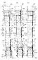
- FIG. 6 (a) and 6 (b) show a conventional method for positioning the decorative sheet 90.
- FIG. Conventionally for example, when the decorative sheet 90 is inclined by the angle ⁇ with respect to the cavity 43 a of the movable mold 43, the cavity 43 a is conventionally controlled by the difference df in movement in the width direction between the feeding device 120 and the winding device 160.
- the inclination of the angle ⁇ of the decorative sheet 90 is adjusted.
- the adjusted angle ⁇ is, for example, about 0.2 degrees, and is usually 0 degree or more and 1.0 degree or less.
- the angle ⁇ formed between the rotation shafts 123a and 162a and the sending direction D1 of the decorative sheet 90 is (90 ⁇ )
- the rotation directions 123a and 162a and the sending direction D1 of the decorative sheet 90 are Are not orthogonal.
- a slack LO may occur as described in FIG. 6B with a slight deformation.
- the conventional positioning method corrects the feeding direction, the width direction, and the inclination of the decorative sheet 90 to correctly align the cavity 43a.
- the inclination angle ⁇ to be adjusted is usually a slight angle of 0 degree or more and 1.0 degree or less
- the decoration sheet 90 is caused by a slight twist of the decoration sheet 90 as shown in FIG.
- a slight sag LO occurs.
- this slight slack LO may cause a shift in a position where fine alignment is required in a fine pattern. If such a condition occurs, a defective product will be formed at the same time as decorative molding. It has been found that there are cases where
- the winding motor 65 is controlled by the control device 80 and the decorative sheet 90 is rotated by the winding roller 64. Align in the feed direction.
- the decorative simultaneous molding system 10 performs positioning in the feed direction by stopping the winding motor 65 when the feed direction position detection mark 91 is detected by the feed direction sensor 81.
- the feed direction position detection mark 91 has a rectangular shape having a long side in the width direction so that the position in the feed direction can be detected even if it is shifted in the width direction.
- the width direction position detection mark 92 is not detected by the first width direction sensor 82, so that the feeding device is relative to the injection molding device 40. 20 and the winding device 60 are moved in the width direction.
- the width direction position detection mark 92 is a belt-like mark extending in the feeding direction of the decorative sheet 90.
- the first side width is obtained by moving the feeding-side guide roller 23 and the like by the feeding-side moving device 24 in the direction of the arrow Ar1 and moving the winding roller 64 and the like by the winding-side moving device 66.
- the direction sensor 82 detects the width direction position detection mark 92 and performs the position adjustment in the width direction.
- the controller 80 decorates the cavity 43a with the decorative sheet 90. Can be detected.
- the device 20 is sent around the first rotating shaft 71 with respect to the cavity 43a of the movable mold 43.
- the winding device 60 is rotated relative to the cavity 43 a of the movable mold 43 around the second rotation shaft 72.
- the rotation directions of the first stepping motor 25 and the third stepping motor 67 are directions to push the mounting plates 41a and 41b in order to rotate clockwise.
- the rotation directions of the second stepping motor 26 and the fourth stepping motor 68 are reversed in the direction in which the pressed mounting plates 41a and 41b can rotate.
- the second width direction sensor 83 detects the width direction position detection mark 92 as shown in FIG. 7C.
- the angle at which the feeding device 20 rotates and the angle at which the winding device 60 rotates are set to be the same. . Even if it rotates in this way, the rotating shaft 23a of the delivery-side guide roller 23 remains in a state orthogonal to the delivery direction D2, and the rotation shaft 64a of the take-up roller 64 is also in the delivery direction D2. Keep orthogonal. As described above, the positional relationship between the feeding-side roller and the winding-side roller and the decorative sheet 90 is correctly maintained, so that it is possible to prevent the occurrence of defective products due to the slack LO.
- the second moving device is configured to rotate in the delivery device 20 by using two units of the first stepping motor 25 and the second stepping motor 26 has been described.
- a second moving device that rotates and moves the feeding device 20 ⁇ / b> A by a single first stepping motor 25 and a stopper 29 is configured.
- the stopper 29 can be constituted by, for example, a stopper that is urged by an air cylinder or a spring, and has a function of pushing the mounting plate 41 a with a force weaker than the driving force of the first stepping motor 25.
- a second moving device that rotationally moves the winding device 60 ⁇ / b> A is configured by one third stepping motor 67 and a stopper 69.
- the stopper 69 can be constituted by, for example, a stopper urged by an air cylinder or a spring, and has a function of pushing the mounting plate 41 b with a force weaker than the driving force of the third stepping motor 67. For example, if the screw 67a of the third stepping motor 67 is retracted, the rod-shaped member 69a of the stopper 69 pushes the mounting plate 41b to rotate the winding device 60A counterclockwise, and if the screw 67a of the third stepping motor 67 is extended, the stopper The 69 rod-shaped members 69a are retracted to rotate and move the winding device 60A clockwise.
- the 2nd moving apparatus is comprised.
- the screws 25a and 67a are expanded and contracted by the first stepping motor 25 and the third stepping motor 67, and the mounting plates 41a and 41b are rotated by the screws 25a and 67a.
- the method of rotating the feeding device and the winding device with one motor is not limited to the configuration of the modified example 4-1.
- the rotation axes 25b and 67b of the first stepping motor 25 and the third stepping motor 67 fixed to the apparatus frames 21 and 61 are set to the first.
- the feeding device 20B and the winding device 60B may be rotated by the rotational force of the first stepping motor 25 and the third stepping motor 67 connected to the rotating shaft 71 and the second rotating shaft 72.
- the mounting plates 41a and 41b, the first stepping motor 25, the third stepping motor 67, the stoppers 29 and 69, the rotating shafts 25b and 67b, the rod-shaped members 29a and 69a, the first rotating shaft 71 and the second rotating shaft 72. Constitutes the second moving device.
- the driving direction of the decorative sheet 90 is limited to the direction of moving toward the take-up roller 64 in the sending direction, but it can be moved in the direction toward the sending roller 22 by attaching a motor to the sending roller 22.
- the width direction alignment is also controlled by detecting the appropriate position by alternately using the first width direction sensor 82 and the second width direction sensor 83 by repeating the movement in the width direction and the rotational movement. Also good.
- the brake mechanism may be provided in the sending roller 22 similarly to 1st Embodiment. (4-4)
- the tension control is performed by the brake control of the feeding roller 22 and the servo mechanism of the electric servo motor of the winding motor 65 has been described.
- the configuration for performing the tension control is another configuration. There may be.
- the winding motor 65 an electric motor other than the electric servo motor can be used.
- a stepping motor is preferably used.
- Second Embodiment (5) Overview of the configuration of the simultaneous decorative molding system
- the feeding device 20 and the winding device 60 are provided with the first rotating shaft 71 and the second rotating shaft 72 as axes.
- the case of rotational movement has been described, but the central axis of rotational movement is arranged on the movable mold 43 as in the decorative simultaneous molding system 10C according to the second embodiment shown in FIG. Also good.
- the simultaneous decorative molding system 10 according to the first embodiment and the simultaneous decorative molding system 10C according to the second embodiment have the same configuration except for the second moving device that rotates and moves.
- molding system 10C which concerns on 2nd Embodiment is demonstrated.
- the decorative simultaneous molding system 10C includes guide rails 75 and 76 for rotating and moving the feeding device 20C and the winding device 60C.
- the guide rails 75 and 76 have an arc shape, and are arranged such that the center CC of the circle is on the cavity 43 a of the movable mold 43.
- the feeding device 20C and the winding device 60C are configured to be movable in an arc along the guide rails 75 and 76 on the guide rails 75 and 76, respectively.
- a driving method of the feeding device 20C and the winding device 60C is a method using a well-known rack and pinion gear and a motor.
- the feeding device 20 ⁇ / b> C and the winding device 60 ⁇ / b> C rotate and move together relative to the movable die 43 while maintaining a relative positional relationship around the rotation center CC set on the movable die 43. It is done. Therefore, for example, when the feeding device 20C is rotated clockwise by an angle ⁇ , the winding device 60C is similarly rotated clockwise by an angle ⁇ .
- the delivery side guide roller 23 that is the delivery side roller and the take-up shaft 62 that is the take-up side roller rotate together with the delivery device 20C and the take-up device 60C.
- the rotation center CC set on the axis 43 as an axis they are rotated and moved together relative to the movable mold 43 while maintaining a relative positional relationship with each other.
- the sending direction D2 of the decorative sheet 90 is orthogonal to the axial direction of both the rotating shafts 23a and 62a such as the sending side guide roller 23 that is the sending side roller and the winding shaft 62 that is the winding side roller. It is done.
- FIG. 11 is a schematic plan view of a decorative simultaneous molding system according to the third embodiment. 11 is different from the simultaneous decorating system 10 shown in FIG. 1 in that the simultaneous decorating system 10D includes a feed direction sensor 81 and a first width direction.
- the sensor 82 and the second width direction sensor 83 are not provided.
- the decorative simultaneous molding system 10D of the third embodiment and the decorative simultaneous molding system 10 of the first embodiment Therefore, the description of the configuration of the decorative simultaneous molding system 10D is omitted.
- the winding motor 65 is controlled by the control device 80 as shown in FIG. 64, the decorative sheet 90D is aligned in the feed direction.
- the decorative simultaneous molding system 10D performs positioning in the feed direction by stopping the winding motor 65 when the feed direction position detection mark 91D is detected by the feed direction sensor 81.
- the feed direction position detection mark 91 ⁇ / b> D has a rectangular shape having a long side in the width direction like the feed direction position detection mark 91 of the first embodiment, but corresponds to the arrangement position of the feed direction sensor 81.
- the feed direction position detection mark 91 is disposed at a position away from the cavity 43a to the upstream side of the conveyance.
- the width direction position detection mark 92 is not detected by either the feed side width direction positioning sensor 86 or the winding side width direction positioning sensor 87.
- the feeding device 20 and the winding device 60 are moved in the width direction relative to 40.
- the decorative sheet 90D is moved in the direction shown by the arrow Ar3.
- the width direction position detection mark 92 is placed on the feed side width direction positioning sensor 86. Detect and perform alignment in the width direction. If the inclination of the decorative sheet 90D is opposite, the winding side width direction positioning sensor 87 detects the width direction position detection mark 92 and performs the width direction alignment.
- the winding side width direction positioning sensor 87 is moved in the width direction position detection mark. Since 92 is not detected, the control device 80 can detect that the decorative sheet 90D is inclined with respect to the cavity 43a.
- the decorating sheet 90D is rotated counterclockwise around the cavity 43a as shown by the arrow Ar4 in FIG.
- the feeding device 60 is rotated about the first rotating shaft 71 and rotated counterclockwise relative to the cavity 43a.
- the winding device 60 is moved about the second rotating shaft 72 to the cavity 43a.
- the rotation direction of the second stepping motor 26 and the fourth stepping motor 68 is a direction of pushing the mounting plates 41a and 41b in order to rotate counterclockwise.
- the rotation directions of the first stepping motor 25 and the third stepping motor 67 are clockwise in the reverse direction in which the pressed mounting plates 41a and 41b can rotate.
- the winding side width direction positioning sensor 87 detects the width direction position detection mark 92 as shown in FIG.
- the angle in the case of rotational movement from the state of FIG. 12B to the state of FIG. 12C is set to be the same for the feeding device 20 and the winding device 60.
- the rotating shaft 23a of the delivery-side guide roller 23 remains in a state orthogonal to the delivery direction, and is wound up.
- the rotating shaft 64a of the roller 64 also maintains a state orthogonal to the delivery direction. In this way, the positional relationship between the feeding-side roller and the winding-side roller and the decorative sheet 90D is correctly maintained, so that it is possible to prevent the occurrence of defective products due to slack.
- the inclination of the decorative sheet 90D is opposite to that in FIG. 12B, and the width-direction position detection mark 92 is first detected by the winding side width-direction positioning sensor 87 to perform the width-direction alignment. Until the feed side width direction positioning sensor 86 detects the width direction position detection mark 92, the feeding device 20 and the winding device 60 are rotated in a clockwise direction.
- the delivery device 20 can be configured to constitute a second moving device that rotates using the first stepping motor 25 and the second stepping motor 26.
- a second moving device that rotates and moves using the third stepping motor 67 and the fourth stepping motor 68 can be configured.
- the 2nd moving apparatus of the structure shown by Fig.9 (a) and FIG.9 (b) can also be used with the decorating simultaneous shaping
- a motor may be attached to the delivery roller 22 so that the decorative sheet 90D can move in the direction toward the delivery roller 22.
- the decorating sheet 90D is appropriately adjusted while moving the decorating sheet 90D back and forth in the sending direction using the feed roller 22 and the take-up roller 64 to make fine adjustments. It can be controlled so that it is detected by the feed side width direction positioning sensor 86 that it has been transported to the correct position. Also, in the alignment in the width direction, by repeating the movement in the width direction and the rotational movement, an appropriate position is detected by alternately using the feed side width direction positioning sensor 86 and the winding side width direction positioning sensor 87. You may control.
- the decorative simultaneous molding system 10C of the second embodiment also uses the decorative sheet 90D as in the third embodiment, and uses a feed direction positioning sensor 85, a feed side width direction positioning sensor 86, and a winding side width direction positioning. It can also be configured to perform symbol alignment according to the detection result of the sensor 87.
- the first stepping motor 25, the second stepping motor 26, and the third stepping motor 67 are used as motors that rotate and move the feeding side roller and the winding side roller of the second moving device.
- the fourth stepping motor 68 is used as an example.
- the motor that rotates and moves the feeding-side roller and the winding-side roller may be a motor that can control the rotation angle or the number of rotations.
- An electric servo motor can be suitably used in place of the stepping motor.
- the decorative simultaneous molding systems 10, 10A, 10B, 10C, and 10D have the feeding devices 20, 20A, 20B, and 20C, the injection molding device 40, and the winding devices 60, 60a, 60B, and 60C. is doing.
- the delivery devices 20, 20A, 20B, and 20C are a delivery roller 22 and a delivery-side guide roller as delivery-side rollers for delivering the decorative sheets 90 and 90D on which patterns for decoration are formed. 23.
- the winding devices 60, 60a, 60B, and 60C include a winding shaft 62, a winding guide roller 63, and a winding roller 64 as a winding roller for winding the decorative sheet.
- the injection molding apparatus 40 includes a movable mold 43 and a fixed mold 44 between the feeding apparatuses 20, 20A, 20B, and 20C and the winding apparatuses 60, 60a, 60B, and 60C.
- the decorative sheets 90 and 90D are disposed in the movable mold 43 and the fixed mold 44, and the decorative sheets 90 and 90D are disposed in the movable mold 43 and the fixed mold 44, and molding is performed simultaneously with the decoration. It is.
- the control apparatus 80, the feed direction sensor 81, the 1st width direction sensor 82, and the 2nd width direction sensor 83 are the designs of the decorating sheet 90 arrange
- a symbol position detecting device for detecting the position of the symbol is configured.
- the control apparatus 80, the feed direction positioning sensor 85, the feed side width direction positioning sensor 86, and the winding side width direction positioning sensor 87 are the decoration sheet 90D arrange
- a symbol position detecting device for detecting a symbol position is configured.
- the feed side moving device 24 and the take-up side moving device 66 are the control device 80, the feed direction sensor 81, the detection result of the first width direction sensor 82 and the second width direction sensor 83 or the feed direction positioning sensor 85, the feed side.
- the feeding side roller and the winding side roller are in the in-plane direction of the parting surface 43b of the movable mold 43 and
- a first moving device is configured to move relative to the movable mold 43 and the fixed mold 44 in the width direction orthogonal to the feeding direction of the decorative sheets 90 and 90D to align the symbols.
- the rotation shaft 72 or the guide rail 75 and the guide rail 76 are detected by the control device 80, the feed direction sensor 81, the first width direction sensor 82 and the second width direction sensor 83 or the feed direction positioning sensor 85, and the feed side width direction positioning.
- the feeding direction of the decorative sheets 90 and 90D is sent in the in-plane direction of the parting surface 43b, and both axes of the feeding side roller and the winding side roller are sent.
- Phase with respect to the movable mold 43 and the fixed mold 44 so as to be orthogonal to the direction.
- the 2nd moving apparatus may be what was demonstrated using Fig.8 (a) and FIG.8 (b), or what was demonstrated using FIG.9 (a) and FIG.9 (b).
- the decorative simultaneous molding system 10, 10A, 10B, 10C, 10D is used in the transporting process.
- the decorative sheets 90 and 90D are placed on the movable mold 43 of the injection molding apparatus 40 disposed between the winding shaft 62, the winding guide roller 63, and the winding roller 64 of 60a, 60B, and 60C.
- a control device 80, a feed direction sensor 81, a first width direction sensor 82 and a second width direction sensor 83, or a feed direction positioning sensor 85, a feed side width direction positioning sensor are placed at predetermined positions of the movable mold 43.
- the winding side width direction positioning sensor 87 are used to align the positions of the symbols.
- a resin molded product decorated with the designs of the decorative sheets 90 and 90D is molded using the movable mold 43 and the fixed mold 44.
- the conveyance position is adjusted by the take-up roller 64 using the feed direction sensor 81.
- the feed side moving device 24 and the winding are arranged in the in-plane direction of the parting surface 43b of the movable mold 43 and in the width direction orthogonal to the feed direction of the decorative sheets 90 and 90D.
- the take-out side moving device 66 is used to move the feeding devices 20, 20A, 20B, 20C and the winding devices 60, 60a, 60B, 60C relative to the movable mold 43 to align the symbols. .
- the feeding direction of the decorative sheets 90 and 90D is sent in the in-plane direction of the parting surface 43b, and the feeding roller 22, the feeding-side guide roller 23, the winding shaft 62, and the winding-side guide roller.
- the feeding devices 20, 20A, 20B, and 20C that is, the feeding-side rollers
- the winding devices 60, 60a, and 63 relative to the movable mold 43 so as to be orthogonal to the axial direction of 63 and the winding roller 64.
- Rotate and move 60B and 60C that is, the take-up roller
- the decorative simultaneous molding systems 10, 10 ⁇ / b> A, 10 ⁇ / b> B, 10 ⁇ / b> C, and 10 ⁇ / b> D configured in this way have an angle in the feeding direction of the decorative sheets 90 and 90 ⁇ / b> D shifted with respect to the movable mold 43 in the angle adjustment process. Further, the detection results of the control device 80, the feed direction sensor 81, the first width direction sensor 82 and the second width direction sensor 83 or the feed direction positioning sensor 85, the feed side width direction positioning sensor 86 and the winding side width direction positioning sensor 87.
- the movable plate is made by the mounting plates 41a and 41b, the first stepping motor 25, the second stepping motor 26, the third stepping motor 67, the fourth stepping motor 68 and the screws 25a, 26a, 67a and 68a.
- the feeding of the decorative sheets 90 and 90D in the in-plane direction of the parting surface 43b of 43 Direction can be orthogonal to the sending roller and for example the winding shaft in both directions of the take-up roller comprising a roller 64 includes a sending-side guide roller 23, for example.
- the axial direction of the feeding-side roller including the feeding-side guide roller 23 and the winding-side roller including, for example, the winding roller 64 is not caused to be orthogonal to the feeding direction of the decorative sheets 90 and 90D.
- the twist of the decorative sheets 90 and 90D can be eliminated, and in the case of simultaneous molding that requires fine alignment, the occurrence of misalignment caused by the twist of the decorative sheet can be suppressed.
- the first rotating shaft 71 rotatably connects the feeding devices 20, 20A, 20B and the injection molding device 40, and the second rotating shaft 72 is connected.
- the injection molding device 40 and the winding devices 60, 60a, 60B are rotatably connected.
- the device 20 is rotated around the first rotating shaft 71 and the device 20 is rotated clockwise, and the winding device 60 is rotated clockwise around the second rotating shaft 72. The case of rotating is described.
- the feeding device 60 is rotated around the first rotation shaft 71 and rotated counterclockwise, and the winding device 60 is rotated counterclockwise around the second rotation shaft 72.
- the feeding direction of the decorative sheets 90 and 90D is sent out in the feeding direction to the axial direction of the roller 22, the feeding side guide roller 23, the winding shaft 62, the winding side guide roller 63, and the winding roller 64.
- the configuration is simplified and the system can be provided at a lower cost than the simultaneous decoration molding system 10C of the second embodiment.
- the guide rails 75 and 76 are used, and the delivery including the delivery-side guide roller 23, for example, with the rotation center CC set on the movable mold 43 as an axis.
- the feeding side roller and the winding side roller are rotated and moved together relative to the movable mold 43 while maintaining the relative positional relationship between the winding side roller and the winding side roller including the winding roller 64, for example.
- the feeding direction of the decorative sheets 90 and 90D is orthogonal to the axial direction of the feeding side roller and the winding side roller.
- the feeding side moving device 24 and the winding side moving device 66 are arranged in the first width direction sensor 82 (an example of a first positioning sensor) that is arranged at the approximate center in the feeding direction of the decorative sheet 90 with respect to the movable mold 43.
- first width direction sensor 82 an example of a first positioning sensor
- movement is performed until a width direction position detection mark 92 (an example of a positioning mark extending in the feeding direction of the decorative sheet 90) is detected (example of the first step).
- a second width direction sensor 83 an example of a second positioning sensor
- the feeding direction of the decorative sheet 90 is rotationally moved (example of the second step).
Landscapes
- Engineering & Computer Science (AREA)
- Manufacturing & Machinery (AREA)
- Mechanical Engineering (AREA)
- Injection Moulding Of Plastics Or The Like (AREA)
Abstract
加飾同時成形システム10は、送出し装置20と巻取り装置60と射出成形装置40とを有している。取付板41a、41b、第1乃至第4ステッピングモーター25,26,67,68、及び第1回転軸71及び第2回転軸72は、第2幅方向センサー83の検出結果に応じて、パーティング面43bの面内方向において加飾シート90の送り方向を、送出し側ガイドローラー23を含む送出し側ローラー及び巻取りローラー64を含む巻取り側ローラーの両方の軸方向に直交させるように、可動金型43及び固定金型44に対して相対的に送出し側ローラーと巻取り側ローラーとを回転移動して図柄の位置合わせ行い、精細な位置合わせを必要とする成形同時加飾の場合の位置ずれの発生を抑制する。
Description
本発明は、加飾シートを用いて樹脂成形品の成形と同時に加飾を行なう加飾同時成形システム及び加飾同時成形品の製造方法に関する。
樹脂成形品の成形時に加飾シートを用いて図柄を転写する転写成形方法は、例えば特許文献1に開示されているように従来から知られている。特許文献1に記載されている転写成形方法における加飾シートと金型との位置合せでは、送り方向の所定位置に加飾シートを搬送した後に、加飾シートの送出し装置と巻取り装置を金型に対して移動させて、送り方向と直交する加飾シートの幅方向に送出し装置と巻取り装置を移動することにより、幅方向の位置ずれと加飾シートの長手方向が金型に対して傾いている状態を修正して、位置決めが行なわれる。
特許文献1に記載されているように、転写成形方法においては、加飾シートの送り方向と幅方向と傾きの修正が行なわれているので、金型に対して加飾シートの図柄の位置合せが正しく行なわれているはずである。
多くの場合には、特許文献1のような位置合せを行なって加飾シートの図柄を金型に配置することにより問題なく成形同時加飾が行なえる。しかし、精細な位置合せを必要とする成形同時加飾の場合には、特許文献1のような位置合せを行なっても、微妙に位置がずれて肉眼ではその図柄のずれが確認できる場合がある。
多くの場合には、特許文献1のような位置合せを行なって加飾シートの図柄を金型に配置することにより問題なく成形同時加飾が行なえる。しかし、精細な位置合せを必要とする成形同時加飾の場合には、特許文献1のような位置合せを行なっても、微妙に位置がずれて肉眼ではその図柄のずれが確認できる場合がある。
本発明の課題は、精細な位置合せを必要とする成形同時加飾の場合の位置ずれの発生を抑制できる加飾同時成形システム及び加飾同時成形品の製造方法を提供することである。
以下に、課題を解決するための手段として複数の態様を説明する。これら態様は、必要に応じて任意に組み合せることができる。
本発明の一見地に係る加飾同時成形システムは、加飾のための図柄が形成されている加飾シートを送り出すための送出し側ローラーを有する送出し装置と、加飾シートを巻き取るための巻取り側ローラーを有する巻取り装置と、送出し装置と巻取り装置との間に加飾シートが配置される金型を有し、金型内に加飾シートを配置した状態で加飾と同時に成形を行なうための射出成形装置と、射出成形装置に配置されている加飾シートの図柄の位置を検出するための図柄位置検出装置と、図柄位置検出装置の検出結果に応じて、送出し側ローラーと巻取り側ローラーとを、金型のパーティング面の面内方向であって且つ加飾シートの送り方向に直交する幅方向に、金型に対して相対的に移動して図柄の位置合せを行なうための第1移動装置と、図柄位置検出装置の検出結果に応じて、金型のパーティング面の面内方向において加飾シートの送り方向を送出し側ローラー及び巻取り側ローラーの両方の軸方向に直交させるように、金型に対して相対的に送出し側ローラーと巻取り側ローラーとを回転移動して図柄の位置合せを行なうための第2移動装置とを備える。
本発明の一見地に係る加飾同時成形システムは、加飾のための図柄が形成されている加飾シートを送り出すための送出し側ローラーを有する送出し装置と、加飾シートを巻き取るための巻取り側ローラーを有する巻取り装置と、送出し装置と巻取り装置との間に加飾シートが配置される金型を有し、金型内に加飾シートを配置した状態で加飾と同時に成形を行なうための射出成形装置と、射出成形装置に配置されている加飾シートの図柄の位置を検出するための図柄位置検出装置と、図柄位置検出装置の検出結果に応じて、送出し側ローラーと巻取り側ローラーとを、金型のパーティング面の面内方向であって且つ加飾シートの送り方向に直交する幅方向に、金型に対して相対的に移動して図柄の位置合せを行なうための第1移動装置と、図柄位置検出装置の検出結果に応じて、金型のパーティング面の面内方向において加飾シートの送り方向を送出し側ローラー及び巻取り側ローラーの両方の軸方向に直交させるように、金型に対して相対的に送出し側ローラーと巻取り側ローラーとを回転移動して図柄の位置合せを行なうための第2移動装置とを備える。
このように構成された加飾同時成形システムでは、金型に対して加飾シートの送り方向の角度がずれているときには、図柄位置検出装置の検出結果に応じて、第2移動装置により、金型に対して相対的に送出し側ローラーと巻取り側ローラーとを回転移動して図柄の位置合せを行なうので、金型のパーティング面の面内方向において加飾シートの送り方向を送出し側ローラー及び巻取り側ローラーの両方の軸方向に直交させることができる。それにより、加飾シートの送り方向と送出し側ローラー及び巻取り側ローラーの軸方向とが直交しないことによって生じていた加飾シートのねじれをなくすことができる。その結果、精細な位置合せを必要とする成形同時加飾の場合に、加飾シートのねじれによって生じていた位置ずれの発生を抑制することができる。
第2移動装置は、送出し装置と射出成形装置とを連結する第1回転軸と、射出成形装置と巻取り装置とを連結する第2回転軸とを有し、第1回転軸を中心に送出し装置を時計回りに回転移動させるとともに第2回転軸を中心に巻取り装置を時計回りに回転移動させることにより又は第1回転軸を中心に送出し装置を反時計回りに回転移動させるとともに第2回転軸を中心に巻取り装置を反時計回りに回転移動させることにより、加飾シートの送り方向を送出し側ローラー及び巻取り側ローラーの両方の軸方向に直交させるように構成されてもよい。
このように構成された加飾同時成形システムでは、射出成形装置の両側に第1回転軸と第2回転軸を設けて、第1回転軸及び第2回転軸を軸としてそれぞれ送出し装置と巻取り装置を同方向に同程度回転させればよいので構成が簡単になってシステムを安価に提供できる。
このように構成された加飾同時成形システムでは、射出成形装置の両側に第1回転軸と第2回転軸を設けて、第1回転軸及び第2回転軸を軸としてそれぞれ送出し装置と巻取り装置を同方向に同程度回転させればよいので構成が簡単になってシステムを安価に提供できる。
第2移動装置は、金型上に設定される回動中心を軸として送出し側ローラーと巻取り側ローラーの相対的な位置関係を保ちつつ金型に対して相対的に送出し側ローラー及び巻取り側ローラーを一緒に回転移動させ、加飾シートの送り方向を送出し側ローラー及び巻取り側ローラーの両方の軸方向に直交させるように構成されてもよい。
このように構成された加飾同時成形システムでは、回転移動させられた後も送出し側ローラーと巻取り側ローラーの相対的な位置関係が保たれるので、加飾シートの送り方向と送出し側ローラーの軸方向及び巻取り側ローラーの軸方向が直行しないことによって生じていた加飾シートのねじれを完全になくすことができる。その結果、精細な位置合せを必要とする成形同時加飾の場合に、加飾シートのねじれによって生じていた位置ずれの発生を防止することができる。
このように構成された加飾同時成形システムでは、回転移動させられた後も送出し側ローラーと巻取り側ローラーの相対的な位置関係が保たれるので、加飾シートの送り方向と送出し側ローラーの軸方向及び巻取り側ローラーの軸方向が直行しないことによって生じていた加飾シートのねじれを完全になくすことができる。その結果、精細な位置合せを必要とする成形同時加飾の場合に、加飾シートのねじれによって生じていた位置ずれの発生を防止することができる。
図柄位置検出装置は、金型に対して加飾シートの送り方向の略中央に配置されている第1位置決めセンサーと、第1位置決めセンサーに対して加飾シートの送り方向に離れた第2位置決めセンサーとを有し、第1移動装置は、加飾シートの送り方向に延びる位置決めマークが第1位置決めセンサーで検出されるまで移動し、第2移動装置は、位置決めマークが第2位置決めセンサーで検出されるまで加飾シートの送り方向を回転移動させるように構成されてもよい。
このように構成された加飾同時成形システムでは、第2移動装置により加飾シートの送り方向を回転移動させても第1位置決めセンサーの回転移動によるずれを小さくでき、第2位置決めセンサーによる位置合せ後に第1位置決めセンサーの位置合わせをする手間を省くことができる。
このように構成された加飾同時成形システムでは、第2移動装置により加飾シートの送り方向を回転移動させても第1位置決めセンサーの回転移動によるずれを小さくでき、第2位置決めセンサーによる位置合せ後に第1位置決めセンサーの位置合わせをする手間を省くことができる。
本発明の一見地に係る加飾同時成形品の製造方法は、加飾シートを送出す送出し装置の送出し側ローラーと加飾シートを巻き取る巻取り装置の巻取り側ローラーとの間に配置されている射出成形装置の金型に、加飾シートを配置するために加飾シートを搬送する搬送工程と、金型の所定位置に、図柄位置検出装置を用いて加飾シートの図柄の位置を合わせる位置合せ工程と、金型を用いて加飾シートの図柄で加飾された樹脂成形品を成形する加飾同時成形工程とを備え、位置合せ工程は、図柄位置検出装置を用いて搬送位置を調整するための搬送位置調整工程と、金型のパーティング面の面内方向であって且つ加飾シートの送り方向に直交する幅方向に金型に対して送出し装置と巻取り装置とを相対的に移動して図柄の位置合せを行なうための幅方向調整工程と、金型のパーティング面の面内方向において加飾シートの送り方向を送出し側ローラー及び巻取り側ローラーの両方の軸方向に直交させるように、金型に対して相対的に送出し側ローラーと巻取り側ローラーとを回転移動して図柄の位置合せを行なうための角度調整工程とを有する。
このように構成された加飾同時成形品の製造方法では、金型に対して加飾シートの送り方向の角度がずれているときには、図柄位置検出装置の検出結果に応じて、角度調整工程において、金型に対して相対的に送出し側ローラーと巻取り側ローラーとを回転移動して図柄の位置合せを行なうので、金型のパーティング面の面内方向において加飾シートの送り方向を送出し側ローラー及び巻取り側ローラーの両方の軸方向に直交させることができる。それにより、加飾シートの送り方向と送出し側ローラー及び巻取り側ローラーの軸方向とが直交しないことによって生じていた加飾シートのねじれをなくすことができる。その結果、精細な位置合せを必要とする成形同時加飾の場合に、加飾シートのねじれによって生じていた位置ずれの発生を抑制することができる。
角度調整工程は、送出し装置と射出成形装置とを連結する第1回転軸を中心に送出し装置を時計回りに回転移動させるとともに射出成形装置と巻取り装置とを連結する第2回転軸を中心に巻取り装置を時計回りに回転移動させることにより又は第1回転軸を中心に送出し装置を反時計回りに回転移動させるとともに第2回転軸を中心に巻取り装置を反時計回りに回転移動させることにより、加飾シートの送り方向を送出し側ローラー及び巻取り側ローラーの両方の軸方向に直交させる工程を含むものであってもよい。
このように構成された加飾同時成形品の製造方法では、射出成形装置の両側に第1回転軸と第2回転軸を設けて、第1回転軸及び第2回転軸を軸としてそれぞれ送出し装置と巻取り装置を同方向に同程度回転させればよいので角度調整が簡単になる。
このように構成された加飾同時成形品の製造方法では、射出成形装置の両側に第1回転軸と第2回転軸を設けて、第1回転軸及び第2回転軸を軸としてそれぞれ送出し装置と巻取り装置を同方向に同程度回転させればよいので角度調整が簡単になる。
角度調整工程は、金型上に設定される回動中心を軸として送出し側ローラーと巻取り側ローラーの相対的な位置関係を保ちつつ金型に対して相対的に送出し側ローラー及び巻取り側ローラーを一緒に回転移動させ、加飾シートの送り方向を送出し側ローラー及び巻取り側ローラーの両方の軸方向に直交させる工程を含むものであってもよい。
このように構成された加飾同時成形品の製造方法では、回転移動させられた後も送出し側ローラーと巻取り側ローラーの相対的な位置関係が保たれるので、加飾シートの送り方向と送出し側ローラー及び巻取り側ローラーの軸方向とが直交しないことによって生じていた加飾シートのねじれを完全になくすことができる。その結果、精細な位置合せを必要とする成形同時加飾の場合に、加飾シートのねじれによって生じていた位置ずれの発生を防止することができる。
このように構成された加飾同時成形品の製造方法では、回転移動させられた後も送出し側ローラーと巻取り側ローラーの相対的な位置関係が保たれるので、加飾シートの送り方向と送出し側ローラー及び巻取り側ローラーの軸方向とが直交しないことによって生じていた加飾シートのねじれを完全になくすことができる。その結果、精細な位置合せを必要とする成形同時加飾の場合に、加飾シートのねじれによって生じていた位置ずれの発生を防止することができる。
位置合せ工程は、金型に対して加飾シートの送り方向の略中央に配置されている第1位置決めセンサーで加飾シートの送り方向に延びる位置決めマークが検出されるまで送り方向と交差する向きに移動する第1工程と、第1位置決めセンサーに対して加飾シートの送り方向に離れた第2位置決めセンサーで位置決めマークが検出されるまで加飾シートの送り方向を回転移動させる第2工程とを含むものであってもよい。
このように構成された加飾同時成形品の製造方法では、第2工程において加飾シートの送り方向を回転移動させても第1位置決めセンサーの回転移動によるずれを小さくでき、第2位置決めセンサーによる位置合せ後に第1位置決めセンサーの位置合わせをする手間を省くことができる。
このように構成された加飾同時成形品の製造方法では、第2工程において加飾シートの送り方向を回転移動させても第1位置決めセンサーの回転移動によるずれを小さくでき、第2位置決めセンサーによる位置合せ後に第1位置決めセンサーの位置合わせをする手間を省くことができる。
本発明に係る加飾同時成形システム又は加飾同時成形品の製造方法では、精細な位置合せを必要とする成形同時加飾の場合の位置ずれの発生を抑制できる。
<第1実施形態>
(1)加飾同時成形システムの構成の概要
本発明の第1実施形態に係る加飾同時成形システムの構成の概要について図1及び図2を用いて説明する。図1は、加飾同時成形システムの模式的な平面図であり、図2及び図3は、加飾同時成形システムの模式的な側面図である。加飾同時成形システム10は、加飾シート90を送出す送出し装置20、加飾シート90を用いて射出成形と同時に成形品の加飾を行なう射出成形装置40、加飾シート90を巻き取る巻取り装置60、及び送出し装置20と射出成形装置40と巻取り装置60を制御する制御装置80を備えている。送出し装置20及び巻取り装置60が箔送り装置を構成する。箔送り装置は、通常、射出成形装置40の可動側に取り付けられる。ただし、金型仕様によっては、箔送り装置が、射出成形装置40の固定側に取り付けられてもよい。
射出成形装置40は、図2に示されているように、可動盤41の上に取り付けられた可動金型43及び固定盤42に取り付けられた固定金型44を有している。なお、図1においては固定盤42及び固定金型44の記載が省略されている。可動金型43にはキャビティ43aが形成され、固定金型44にはキャビティ43aに対応するコア44aが形成されている。
(1)加飾同時成形システムの構成の概要
本発明の第1実施形態に係る加飾同時成形システムの構成の概要について図1及び図2を用いて説明する。図1は、加飾同時成形システムの模式的な平面図であり、図2及び図3は、加飾同時成形システムの模式的な側面図である。加飾同時成形システム10は、加飾シート90を送出す送出し装置20、加飾シート90を用いて射出成形と同時に成形品の加飾を行なう射出成形装置40、加飾シート90を巻き取る巻取り装置60、及び送出し装置20と射出成形装置40と巻取り装置60を制御する制御装置80を備えている。送出し装置20及び巻取り装置60が箔送り装置を構成する。箔送り装置は、通常、射出成形装置40の可動側に取り付けられる。ただし、金型仕様によっては、箔送り装置が、射出成形装置40の固定側に取り付けられてもよい。
射出成形装置40は、図2に示されているように、可動盤41の上に取り付けられた可動金型43及び固定盤42に取り付けられた固定金型44を有している。なお、図1においては固定盤42及び固定金型44の記載が省略されている。可動金型43にはキャビティ43aが形成され、固定金型44にはキャビティ43aに対応するコア44aが形成されている。
送出し装置20は装置フレーム21を有し、巻取り装置60は装置フレーム61を有している。送出し装置20は、加飾シート90を送出す送出しローラー22と送出し側ガイドローラー23と有し、これら送出しローラー22と送出し側ガイドローラー23とが回転可能に装置フレーム21に取り付けられている。一方、巻取り装置60は、加飾シート90を巻き取る巻取りシャフト62と巻取り側ガイドローラー63と2本の巻取りローラー64とを有し、これら巻き取る巻取りシャフト62と巻取り側ガイドローラー63と2本の巻取りローラー64とが回転可能に装置フレーム61に取り付けられている。また、巻取り装置60は、巻取りローラー64を駆動するための巻取り用モーター65を有している。巻取り用モーター65は、例えばサーボモーターであり、トルク及び搬送位置を精度良く制御することができる。巻取り用モーター65で巻取りローラー64が駆動されることにより、2本の巻取りローラー64で加飾シート90が挟まれて、加飾シート90が搬送される。加飾シート90が搬送されるときには、加飾シート90に適切なテンションが掛かるように送出しローラー22がブレーキ制御される。従って、送出しローラー22で発生されたブレーキの力が巻取り用モーター65のトルクより大きくなって、巻取り用モーター65の駆動が停止されると、加飾シート90が弛むことなく停止した状態を保つことができる。加飾シート90は、例えば、樹脂製のベースフィルムに剥離層と図柄インキ層と接着剤層とが積層されてなる。この加飾シート90のベースフィルムは、巻取り用モーター65の駆動力によって掛かる張力程度ではほとんど伸び縮みしない強度を備えている。そして、加飾シート90の搬送時には上述のように送出しローラー22と巻取り用モーター65によるテンションコントロールが行なわれ、加飾シート90の張力が所定値以下の一定の値に制御され、加飾シート90の伸び縮みによる誤差が抑制されている。なお、図1においては、加飾同時成形システム10の構成を見易くするために加飾シート90の図柄インキ層の図柄などの記載は省いている。
可動金型43のパーティング面43bには、クランプ45が配置されている。また、可動金型43のキャビティ43aの中には、加飾シート90を吸引するための複数の吸引口(図示せず)が形成されている。加飾シート90の位置決めが終わった後、加飾シート90はキャビティ43aの吸引口に吸い付けられた状態でクランプ45によって挟まれて固定される。加飾シート90の位置決めが終了してキャビティ43aの中に吸引される前の状態が図2に示され、クランプ45によって加飾シート90の固定が終了した状態が図3に示されている。
図3に示されている状態から、射出成形装置40は、さらに可動盤41が固定盤42の方に向かって移動して固定金型44に可動金型43を型締めする。そして、射出成形装置40は、型締めされた可動金型43と固定金型44のキャビティ43aとコア44aによって形成されるキャビティ空間に対し、射出ノズル(図示せず)から溶融樹脂を射出して、樹脂成形品を成形すると同時に加飾シート90の図柄を樹脂成形品に転写する。
図3に示されている状態から、射出成形装置40は、さらに可動盤41が固定盤42の方に向かって移動して固定金型44に可動金型43を型締めする。そして、射出成形装置40は、型締めされた可動金型43と固定金型44のキャビティ43aとコア44aによって形成されるキャビティ空間に対し、射出ノズル(図示せず)から溶融樹脂を射出して、樹脂成形品を成形すると同時に加飾シート90の図柄を樹脂成形品に転写する。
(2)加飾シートの位置決めのための構成
上述のようにして可動金型43と固定金型44を使って成形される加飾同時成形品を美しく仕上げるためには、可動金型43のキャビティ43aに吸着される加飾シート90を可動金型43に対して精度良く位置決めしなくてはならない。そのために、加飾シート90に送出し装置20と巻取り装置60が制御装置80によって制御されている。
上述のようにして可動金型43と固定金型44を使って成形される加飾同時成形品を美しく仕上げるためには、可動金型43のキャビティ43aに吸着される加飾シート90を可動金型43に対して精度良く位置決めしなくてはならない。そのために、加飾シート90に送出し装置20と巻取り装置60が制御装置80によって制御されている。
(2-1)各部のセンサー
制御装置80には、送り方向センサー81と第1幅方向センサー82と第2幅方向センサー83とが接続されている。送り方向センサー81と第1幅方向センサー82と第2幅方向センサー83とは、図1に示されているように例えば可動金型43に取り付けられている。送り方向センサー81は、例えば、加飾シート90の送り方向に向かってキャビティ43aの右側に配置される。一方、第1幅方向センサー82及び第2幅方向センサー83は、送り方向に向かってキャビティ43aの左側に配置されており、第1幅方向センサー82がキャビティ43aの長手方向略中央に位置し、第2幅方向センサー83が第1幅方向センサー82の送り方向上流に位置する。
また、制御装置80には、送り方向位置決めセンサー85、送り側幅方向位置決めセンサー86及び巻取り側幅方向位置決めセンサー87が接続されている。加飾シート90を速く移動させるために、第1実施形態では、巻取りローラー64によって巻き取られる加飾シート90のおおよその位置決めが、送り方向位置決めセンサー85によって行なわれる。その後の送り方向の加飾シート90の詳細な位置決めは送り方向センサー81によって行なわれる。また、送出し装置20と射出成形装置40との相対的な幅方向の位置関係が送り側幅方向位置決めセンサー86によって検出され、射出成形装置40と巻取り装置60の相対的な幅方向の位置関係が巻取り側幅方向位置決めセンサー87によって検出される。例えば、繰り返し加飾シート90を搬送するときにずれが生じるのを修正するために、これら送り側幅方向位置決めセンサー86及び巻取り側幅方向位置決めセンサー87によって、送出し装置20と射出成形装置40と巻取り装置60の幅方向の相対的な位置関係が調節される。
制御装置80には、送り方向センサー81と第1幅方向センサー82と第2幅方向センサー83とが接続されている。送り方向センサー81と第1幅方向センサー82と第2幅方向センサー83とは、図1に示されているように例えば可動金型43に取り付けられている。送り方向センサー81は、例えば、加飾シート90の送り方向に向かってキャビティ43aの右側に配置される。一方、第1幅方向センサー82及び第2幅方向センサー83は、送り方向に向かってキャビティ43aの左側に配置されており、第1幅方向センサー82がキャビティ43aの長手方向略中央に位置し、第2幅方向センサー83が第1幅方向センサー82の送り方向上流に位置する。
また、制御装置80には、送り方向位置決めセンサー85、送り側幅方向位置決めセンサー86及び巻取り側幅方向位置決めセンサー87が接続されている。加飾シート90を速く移動させるために、第1実施形態では、巻取りローラー64によって巻き取られる加飾シート90のおおよその位置決めが、送り方向位置決めセンサー85によって行なわれる。その後の送り方向の加飾シート90の詳細な位置決めは送り方向センサー81によって行なわれる。また、送出し装置20と射出成形装置40との相対的な幅方向の位置関係が送り側幅方向位置決めセンサー86によって検出され、射出成形装置40と巻取り装置60の相対的な幅方向の位置関係が巻取り側幅方向位置決めセンサー87によって検出される。例えば、繰り返し加飾シート90を搬送するときにずれが生じるのを修正するために、これら送り側幅方向位置決めセンサー86及び巻取り側幅方向位置決めセンサー87によって、送出し装置20と射出成形装置40と巻取り装置60の幅方向の相対的な位置関係が調節される。
(2-2)移動機構
上述のように制御装置80が位置決めを行なうために、加飾同時成形システム10は、可動金型43及び固定金型44に対して加飾シート90を移動させる移動機構を備えている。既に説明したが、加飾シート90を送り方向に移動するのは巻取りローラー64と巻取り用モーター65であり、これら巻取りローラー64と巻取り用モーター65は送り方向に加飾シート90を移動する移動機構である。また、射出成形装置40に対して送出し装置20を幅方向に相対的に移動させるために送出し装置20には送り側移動装置24が設けられており、射出成形装置40に対して巻取り装置60を幅方向に相対的に移動させるために巻取り装置60には巻取り側移動装置66が設けられている。
さらに、図4(a)及び図5(a)に示されているように、送出し装置20と射出成形装置40とを連結する第1回転軸71の周りに送出し装置20を回転移動させるために、第1ステッピングモーター25と第2ステッピングモーター26が設けられている。また、図4(b)及び図5(b)に示されているように、巻取り装置60と射出成形装置40とを連結する第2回転軸72の周りに巻取り装置60を回転移動させるために、第3ステッピングモーター67と第4ステッピングモーター68が設けられている。
これら第1ステッピングモーター25、第2ステッピングモーター26、第3ステッピングモーター67及び第4ステッピングモーター68並びに送り側移動装置24及び巻取り側移動装置66は、制御装置80によって制御されている。
上述のように制御装置80が位置決めを行なうために、加飾同時成形システム10は、可動金型43及び固定金型44に対して加飾シート90を移動させる移動機構を備えている。既に説明したが、加飾シート90を送り方向に移動するのは巻取りローラー64と巻取り用モーター65であり、これら巻取りローラー64と巻取り用モーター65は送り方向に加飾シート90を移動する移動機構である。また、射出成形装置40に対して送出し装置20を幅方向に相対的に移動させるために送出し装置20には送り側移動装置24が設けられており、射出成形装置40に対して巻取り装置60を幅方向に相対的に移動させるために巻取り装置60には巻取り側移動装置66が設けられている。
さらに、図4(a)及び図5(a)に示されているように、送出し装置20と射出成形装置40とを連結する第1回転軸71の周りに送出し装置20を回転移動させるために、第1ステッピングモーター25と第2ステッピングモーター26が設けられている。また、図4(b)及び図5(b)に示されているように、巻取り装置60と射出成形装置40とを連結する第2回転軸72の周りに巻取り装置60を回転移動させるために、第3ステッピングモーター67と第4ステッピングモーター68が設けられている。
これら第1ステッピングモーター25、第2ステッピングモーター26、第3ステッピングモーター67及び第4ステッピングモーター68並びに送り側移動装置24及び巻取り側移動装置66は、制御装置80によって制御されている。
第1ステッピングモーター25及び第2ステッピングモーター26は、装置フレーム21に固定されている。第1ステッピングモーター25及び第2ステッピングモーター26の回転軸には、それぞれネジ25a,26aが取り付けられている。これらネジ25a,26aは、一方端側が装置フレーム21に形成されているネジ穴(図示せず)に取り付けられており、他方端側が取付板41aに当接するように配置されている。この取付板41aは、射出成形装置40の可動盤41に第1回転軸71を取り付けるための部材である。第1回転軸71は、装置フレーム21の軸穴21aに回動可能に嵌め込まれる。
このような構成により、第1ステッピングモーター25及び第2ステッピングモーター26の回転に応じて装置フレーム21のネジ穴から取付板41aに当接している位置までの距離を変えることができる。第1ステッピングモーター25がネジ25aを回転させることでネジ25aが取付板41aを押してネジ穴と取付板41aの距離が長くなれば、送出し装置20は、射出成形装置40に対して時計回りに回転する。このとき、第2ステッピングモーター26は、ネジ穴と取付板41aの距離が短くなるようにネジ26aの回転を制御される。逆に、第2ステッピングモーター26がネジ26aを回転させることでネジ26aが取付板41aを押してネジ穴と取付板41aの距離が長くなれば、送出し装置20は、射出成形装置40に対して反時計回りに回転する。このとき、第1ステッピングモーター25は、ネジ穴と取付板41aの距離が短くなるようにネジ25aの回転を制御される。
同様に、第3ステッピングモーター67及び第4ステッピングモーター68は、装置フレーム61に固定されている。第3ステッピングモーター67及び第4ステッピングモーター68の回転軸には、それぞれネジ67a,68aが取り付けられている。これらネジ67a,68aは、一方端側が装置フレーム61に形成されているネジ穴(図示せず)に取り付けられており、他方端側が取付板41bに当接するように配置されている。この取付板41bは、射出成形装置40の可動盤41に第2回転軸72を取り付けるための部材である。第2回転軸72は、装置フレーム61の軸穴61aに回動可能に嵌め込まれる。
このような構成により、第1ステッピングモーター25及び第2ステッピングモーター26の回転に応じて装置フレーム21のネジ穴から取付板41aに当接している位置までの距離を変えることができる。第1ステッピングモーター25がネジ25aを回転させることでネジ25aが取付板41aを押してネジ穴と取付板41aの距離が長くなれば、送出し装置20は、射出成形装置40に対して時計回りに回転する。このとき、第2ステッピングモーター26は、ネジ穴と取付板41aの距離が短くなるようにネジ26aの回転を制御される。逆に、第2ステッピングモーター26がネジ26aを回転させることでネジ26aが取付板41aを押してネジ穴と取付板41aの距離が長くなれば、送出し装置20は、射出成形装置40に対して反時計回りに回転する。このとき、第1ステッピングモーター25は、ネジ穴と取付板41aの距離が短くなるようにネジ25aの回転を制御される。
同様に、第3ステッピングモーター67及び第4ステッピングモーター68は、装置フレーム61に固定されている。第3ステッピングモーター67及び第4ステッピングモーター68の回転軸には、それぞれネジ67a,68aが取り付けられている。これらネジ67a,68aは、一方端側が装置フレーム61に形成されているネジ穴(図示せず)に取り付けられており、他方端側が取付板41bに当接するように配置されている。この取付板41bは、射出成形装置40の可動盤41に第2回転軸72を取り付けるための部材である。第2回転軸72は、装置フレーム61の軸穴61aに回動可能に嵌め込まれる。
このような構成により、第3ステッピングモーター67及び第4ステッピングモーター68の回転に応じて装置フレーム61のネジ穴から取付板41bに当接している位置までの距離を変えることができる。第3ステッピングモーター67がネジ67aを回転させることでネジ67aが取付板41bを押して装置フレーム61のネジ穴と取付板41bの距離が長くなれば、巻取り装置60は、射出成形装置40に対して時計回りに回転する。このとき、第4ステッピングモーター68は、ネジ穴と取付板41bの距離が短くなるようにネジ68aの回転を制御される。逆に、第4ステッピングモーター68がネジ68aを回転させることで取付板41bが押されてネジ穴と取付板41bの距離が長くなれば、巻取り装置60は、射出成形装置40に対して反時計回りに回転する。このとき、第3ステッピングモーター67は、ネジ穴と取付板41bの距離が短くなるようにネジ67aの回転を制御される。
(3)加飾シートの位置決め動作
まず、特許文献1などに記載されている従来の加飾シートの位置決め方法の問題点について詳細に説明した後、本発明に係る加飾シートの位置決め方法について説明する。図6(a)及び図6(b)には、従来の加飾シート90の位置決めの方法が示されている。従来は、例えば可動金型43のキャビティ43aに対して加飾シート90が角度θだけ傾いていた場合、従来は、送出し装置120と巻取り装置160の幅方向の移動の差dfによってキャビティ43aと加飾シート90の角度θの傾きを調整している。調整される角度θは、例えば0.2度程度であり、通常0度以上1.0度以下である。この場合、送出し装置120と巻取り装置160の幅方向の移動によって、例えば送出し装置120の送出し側ガイドローラー123及び巻取りシャフト162を見ると、角度θの調整前後で角度が変わっていないため、それぞれの回転軸123a,162aと加飾シート90の送出し方向D1のなす角αは、(90-θ)になり、回転軸123a,162aと加飾シート90の送出し方向D1とが直交しない。そのために、図6(b)において少しデフォルメして記載しているように、弛みLOが生じてしまうことがある。図6(a)に示されているように、従来の位置合せ方法でも、加飾シート90の送り方向、幅方向及び傾きを修正して正しくキャビティ43aに対する位置合せができているので、加飾時の位置ずれはほとんど発生しない。調整する傾きの角度θが通常0度以上1.0度以下の僅かな角度であるが、図6(b)に示されているように、加飾シート90の僅かなねじれによって加飾シート90の僅かな弛みLOが発生する。鋭意検討した結果、この僅かな弛みLOでも精細な絵柄において精細な位置合せが必要な箇所にずれを生じさせることがあり、たまたまそのような条件が重なると加飾同時成形時に不良品を成形してしまう場合のあることが見出された。
まず、特許文献1などに記載されている従来の加飾シートの位置決め方法の問題点について詳細に説明した後、本発明に係る加飾シートの位置決め方法について説明する。図6(a)及び図6(b)には、従来の加飾シート90の位置決めの方法が示されている。従来は、例えば可動金型43のキャビティ43aに対して加飾シート90が角度θだけ傾いていた場合、従来は、送出し装置120と巻取り装置160の幅方向の移動の差dfによってキャビティ43aと加飾シート90の角度θの傾きを調整している。調整される角度θは、例えば0.2度程度であり、通常0度以上1.0度以下である。この場合、送出し装置120と巻取り装置160の幅方向の移動によって、例えば送出し装置120の送出し側ガイドローラー123及び巻取りシャフト162を見ると、角度θの調整前後で角度が変わっていないため、それぞれの回転軸123a,162aと加飾シート90の送出し方向D1のなす角αは、(90-θ)になり、回転軸123a,162aと加飾シート90の送出し方向D1とが直交しない。そのために、図6(b)において少しデフォルメして記載しているように、弛みLOが生じてしまうことがある。図6(a)に示されているように、従来の位置合せ方法でも、加飾シート90の送り方向、幅方向及び傾きを修正して正しくキャビティ43aに対する位置合せができているので、加飾時の位置ずれはほとんど発生しない。調整する傾きの角度θが通常0度以上1.0度以下の僅かな角度であるが、図6(b)に示されているように、加飾シート90の僅かなねじれによって加飾シート90の僅かな弛みLOが発生する。鋭意検討した結果、この僅かな弛みLOでも精細な絵柄において精細な位置合せが必要な箇所にずれを生じさせることがあり、たまたまそのような条件が重なると加飾同時成形時に不良品を成形してしまう場合のあることが見出された。
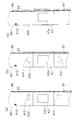
そこで、第1実施形態の加飾同時成形システム10では、図7(a)に示されているように、制御装置80によって巻取り用モーター65を制御して巻取りローラー64により加飾シート90の送り方向の位置合せを行なう。加飾同時成形システム10は、送り方向位置検出マーク91が送り方向センサー81によって検出された時点で巻取り用モーター65を停止させることにより送り方向の位置合せを行なう。送り方向位置検出マーク91は、幅方向にずれても送り方向の位置を検出できるように、幅方向に長辺を持つ長方形の形状を持っている。
送り方向の位置合せが終了した図7(a)の時点で、幅方向位置検出マーク92が第1幅方向センサー82で検出されていないので、射出成形装置40に対して相対的に送出し装置20及び巻取り装置60を幅方向に移動させる。幅方向位置検出マーク92は、加飾シート90の送り方向に延びる帯状のマークである。図7(a)では、矢印Ar1の方向に送り側移動装置24により送出し側ガイドローラー23などを移動させ、巻取り側移動装置66により巻取りローラー64などを移動させることによって、第1幅方向センサー82に幅方向位置検出マーク92を検出させて幅方向の位置合せを行なう。
送り方向の位置合せが終了した図7(a)の時点で、幅方向位置検出マーク92が第1幅方向センサー82で検出されていないので、射出成形装置40に対して相対的に送出し装置20及び巻取り装置60を幅方向に移動させる。幅方向位置検出マーク92は、加飾シート90の送り方向に延びる帯状のマークである。図7(a)では、矢印Ar1の方向に送り側移動装置24により送出し側ガイドローラー23などを移動させ、巻取り側移動装置66により巻取りローラー64などを移動させることによって、第1幅方向センサー82に幅方向位置検出マーク92を検出させて幅方向の位置合せを行なう。
次に、図7(b)に示されている状態では、第2幅方向センサー83が幅方向位置検出マーク92を検出していないので、制御装置80は、キャビティ43aに対して加飾シート90が傾いていることを検出できる。加飾シート90の傾きを修正するために、図7(b)に矢印Ar2で示されているように、第1回転軸71を中心に送出し装置20を可動金型43のキャビティ43aに対して相対的に回転移動させ、第2回転軸72を中心に巻取り装置60を可動金型43のキャビティ43aに対して相対的に回転移動させる。図7(b)に示されている場合は、時計回りに回転させるために第1ステッピングモーター25及び第3ステッピングモーター67の回転方向は取付板41a,41bを押す方向である。このとき第2ステッピングモーター26及び第4ステッピングモーター68の回転方向は押された取付板41a,41bが回転できる方向に逆に回る。
送出し装置20及び巻取り装置60が回転移動すると、図7(c)に示されているように、第2幅方向センサー83が幅方向位置検出マーク92を検出する。図7(b)の状態から図7(c)の状態になるときに送出し装置20が回転移動する角度と巻取り装置60が回転移動する角度とは、互いに同じになるように設定される。このようにして回転移動しても、送出し側ガイドローラー23の回転軸23aは送出し方向D2に対して直交した状態を保ち、巻取りローラー64の回転軸64aも送出し方向D2に対して直交した状態を保つ。このように送出し側のローラー及び巻取り側のローラーと加飾シート90の位置関係が正しく保たれるので、弛みLOによる不良品の発生を防止することができる。
送出し装置20及び巻取り装置60が回転移動すると、図7(c)に示されているように、第2幅方向センサー83が幅方向位置検出マーク92を検出する。図7(b)の状態から図7(c)の状態になるときに送出し装置20が回転移動する角度と巻取り装置60が回転移動する角度とは、互いに同じになるように設定される。このようにして回転移動しても、送出し側ガイドローラー23の回転軸23aは送出し方向D2に対して直交した状態を保ち、巻取りローラー64の回転軸64aも送出し方向D2に対して直交した状態を保つ。このように送出し側のローラー及び巻取り側のローラーと加飾シート90の位置関係が正しく保たれるので、弛みLOによる不良品の発生を防止することができる。
(4)変形例
(4-1)
上記第1実施形態では、送出し装置20において、第1ステッピングモーター25及び第2ステッピングモーター26の2台を使って回転移動させる第2移動装置を構成する例を説明したが、第2移動装置は1台のモーターで構成してもよい。例えば図8(a)に記載されているように、1台の第1ステッピングモーター25とストッパー29とで送出し装置20Aを回転移動させる第2移動装置が構成される。ストッパー29は、例えばエアシリンダー又はバネで付勢するストッパーで構成でき、第1ステッピングモーター25の駆動力よりも弱い力で取付板41aを押す機能を有する。例えば、第1ステッピングモーター25のネジ25aが引っ込めばストッパー29の棒状部材29aが取付板41aを押して送出し装置20Aを反時計回りに回転移動させ、第1ステッピングモーター25のネジ25aが伸びればストッパー29の棒状部材29aが引っ込んで送出し装置20Aを時計回りに回転移動させる。
例えば図8(b)に記載されているように、1台の第3ステッピングモーター67とストッパー69とで巻取り装置60Aを回転移動させる第2移動装置が構成される。ストッパー69は、例えばエアシリンダー又はバネで付勢するストッパーで構成でき、第3ステッピングモーター67の駆動力よりも弱い力で取付板41bを押す機能を有する。例えば、第3ステッピングモーター67のネジ67aが引っ込めばストッパー69の棒状部材69aが取付板41bを押して巻取り装置60Aを反時計回りに回転移動させ、第3ステッピングモーター67のネジ67aが伸びればストッパー69の棒状部材69aが引っ込んで巻取り装置60Aを時計回りに回転移動させる。この場合は、取付板41a,41b、第1ステッピングモーター25、第3ステッピングモーター67、ストッパー29,69、ネジ25a,67a、棒状部材29a,69a並びに第1回転軸71及び第2回転軸72が第2移動装置を構成している。
(4-1)
上記第1実施形態では、送出し装置20において、第1ステッピングモーター25及び第2ステッピングモーター26の2台を使って回転移動させる第2移動装置を構成する例を説明したが、第2移動装置は1台のモーターで構成してもよい。例えば図8(a)に記載されているように、1台の第1ステッピングモーター25とストッパー29とで送出し装置20Aを回転移動させる第2移動装置が構成される。ストッパー29は、例えばエアシリンダー又はバネで付勢するストッパーで構成でき、第1ステッピングモーター25の駆動力よりも弱い力で取付板41aを押す機能を有する。例えば、第1ステッピングモーター25のネジ25aが引っ込めばストッパー29の棒状部材29aが取付板41aを押して送出し装置20Aを反時計回りに回転移動させ、第1ステッピングモーター25のネジ25aが伸びればストッパー29の棒状部材29aが引っ込んで送出し装置20Aを時計回りに回転移動させる。
例えば図8(b)に記載されているように、1台の第3ステッピングモーター67とストッパー69とで巻取り装置60Aを回転移動させる第2移動装置が構成される。ストッパー69は、例えばエアシリンダー又はバネで付勢するストッパーで構成でき、第3ステッピングモーター67の駆動力よりも弱い力で取付板41bを押す機能を有する。例えば、第3ステッピングモーター67のネジ67aが引っ込めばストッパー69の棒状部材69aが取付板41bを押して巻取り装置60Aを反時計回りに回転移動させ、第3ステッピングモーター67のネジ67aが伸びればストッパー69の棒状部材69aが引っ込んで巻取り装置60Aを時計回りに回転移動させる。この場合は、取付板41a,41b、第1ステッピングモーター25、第3ステッピングモーター67、ストッパー29,69、ネジ25a,67a、棒状部材29a,69a並びに第1回転軸71及び第2回転軸72が第2移動装置を構成している。
(4-2)
上述の変形例4-1では、第1ステッピングモーター25及び第3ステッピングモーター67でネジ25a,67aを伸縮させてネジ25a,67aで取付板41a,41bを回転移動させた。しかし、1台のモーターで送出し装置及び巻取り装置を回転移動させる方法は変形例4-1の構成に限られない。例えば、図9(a)及び図9(b)に示されているように、装置フレーム21,61に固定された第1ステッピングモーター25及び第3ステッピングモーター67の回転軸25b,67bを第1回転軸71及び第2回転軸72に接続して第1ステッピングモーター25及び第3ステッピングモーター67の回転力で送出し装置20B及び巻取り装置60Bを回転移動させてもよい。この場合は、取付板41a,41b、第1ステッピングモーター25、第3ステッピングモーター67、ストッパー29,69、回転軸25b,67b、棒状部材29a,69a並びに第1回転軸71及び第2回転軸72が第2移動装置を構成している。
上述の変形例4-1では、第1ステッピングモーター25及び第3ステッピングモーター67でネジ25a,67aを伸縮させてネジ25a,67aで取付板41a,41bを回転移動させた。しかし、1台のモーターで送出し装置及び巻取り装置を回転移動させる方法は変形例4-1の構成に限られない。例えば、図9(a)及び図9(b)に示されているように、装置フレーム21,61に固定された第1ステッピングモーター25及び第3ステッピングモーター67の回転軸25b,67bを第1回転軸71及び第2回転軸72に接続して第1ステッピングモーター25及び第3ステッピングモーター67の回転力で送出し装置20B及び巻取り装置60Bを回転移動させてもよい。この場合は、取付板41a,41b、第1ステッピングモーター25、第3ステッピングモーター67、ストッパー29,69、回転軸25b,67b、棒状部材29a,69a並びに第1回転軸71及び第2回転軸72が第2移動装置を構成している。
(4-3)
上記第1実施形態では、送出しローラー22及び送出し側ガイドローラー23が巻取りローラー64の駆動力によって駆動される従動ローラーの場合について説明した。そのため、加飾シート90の駆動方向は送出し方向において巻取りローラー64に向かって動く向きだけに限られていたが、送出しローラー22にモーターを取り付けて送出しローラー22に向かう向きに移動できるように構成してもよい。このような構成によれば、位置合せのときに、送出しローラー22と巻取りローラー64を使って送出し方向において前後に加飾シート90を動かして微調整しながら、加飾シート90が適切な位置に搬送されたことを送り方向センサー81によって検出するように制御することができる。また、幅方向の位置合せも、幅方向の移動と回転移動を繰り返して、第1幅方向センサー82及び第2幅方向センサー83を交互に使うことによって適切な位置を検出するように制御してもよい。なお、このようの構成にする場合、第1実施形態と同様に送出しローラー22にブレーキ機構が設けられていてもよい。
(4-4)
上記第1実施形態では、送出しローラー22のブレーキ制御と巻取り用モーター65の電動サーボモーターのサーボ機構によってテンションコントロールを行なう場合について説明したが、テンションコントロールを行なうための構成は他の構成であってもよい。巻取り用モーター65には、電動サーボモーター以外の電動機を用いることができ、例えば、ステッピングモーターが好適に用いられる。
上記第1実施形態では、送出しローラー22及び送出し側ガイドローラー23が巻取りローラー64の駆動力によって駆動される従動ローラーの場合について説明した。そのため、加飾シート90の駆動方向は送出し方向において巻取りローラー64に向かって動く向きだけに限られていたが、送出しローラー22にモーターを取り付けて送出しローラー22に向かう向きに移動できるように構成してもよい。このような構成によれば、位置合せのときに、送出しローラー22と巻取りローラー64を使って送出し方向において前後に加飾シート90を動かして微調整しながら、加飾シート90が適切な位置に搬送されたことを送り方向センサー81によって検出するように制御することができる。また、幅方向の位置合せも、幅方向の移動と回転移動を繰り返して、第1幅方向センサー82及び第2幅方向センサー83を交互に使うことによって適切な位置を検出するように制御してもよい。なお、このようの構成にする場合、第1実施形態と同様に送出しローラー22にブレーキ機構が設けられていてもよい。
(4-4)
上記第1実施形態では、送出しローラー22のブレーキ制御と巻取り用モーター65の電動サーボモーターのサーボ機構によってテンションコントロールを行なう場合について説明したが、テンションコントロールを行なうための構成は他の構成であってもよい。巻取り用モーター65には、電動サーボモーター以外の電動機を用いることができ、例えば、ステッピングモーターが好適に用いられる。
<第2実施形態>
(5)加飾同時成形システムの構成の概要
上記第1実施形態の加飾同時成形システム10では、第1回転軸71と第2回転軸72を軸として送出し装置20及び巻取り装置60を回転移動させる場合について説明したが、図10に示されている第2実施形態に係る加飾同時成形システム10Cのように、回転移動の中心軸を可動金型43の上に配置するようにしてもよい。従って、第1実施形態に係る加飾同時成形システム10と第2実施形態に係る加飾同時成形システム10Cとは、回転移動させる第2移動装置以外は同様の構成を有しているので、以下においては、第2実施形態に係る加飾同時成形システム10Cの回転移動のための第2移動装置について説明する。加飾同時成形システム10Cにおいて、回転移動のための装置以外の加飾同時成形システム10と同一の符号を付した部分は加飾同時成形システム10と同様の部分である。
第2実施形態に係る加飾同時成形システム10Cは、送出し装置20C及び巻取り装置60Cを回転移動させるためのガイドレール75,76を備えている。ガイドレール75,76は、円弧状の形状をしており、円の中心CCが可動金型43のキャビティ43aの上に在るように配置されている。
送出し装置20C及び巻取り装置60Cは、それぞれガイドレール75,76の上をガイドレール75,76に沿って円弧状に移動可能に構成されている。送出し装置20C及び巻取り装置60Cの駆動方法は、周知のラックアンドピニオンギアなどとモーターを用いるものなどである。送出し装置20C及び巻取り装置60Cは、可動金型43上に設定される回動中心CCを軸として相対的な位置関係を保ちつつ可動金型43に対して相対的に一緒に回転移動させられる。そのために、例えば送出し装置20Cが時計回りに角度θだけ回転させられるときには、巻取り装置60Cも同様に時計回りに角度θだけ回転させられる。その結果、送出し側ローラーである送出し側ガイドローラー23など及び巻取り側ローラーである巻取りシャフト62などは、送出し装置20C及び巻取り装置60Cと一緒に回転移動するので、可動金型43上に設定される回動中心CCを軸として互いに相対的な位置関係を保ちつつ可動金型43に対して相対的に一緒に回転移動させられることになる。そして、加飾シート90の送出し方向D2を送出し側ローラーである送出し側ガイドローラー23など及び巻取り側ローラーである巻取りシャフト62など両方の回転軸23a,62aの軸方向に直交させられる。
(5)加飾同時成形システムの構成の概要
上記第1実施形態の加飾同時成形システム10では、第1回転軸71と第2回転軸72を軸として送出し装置20及び巻取り装置60を回転移動させる場合について説明したが、図10に示されている第2実施形態に係る加飾同時成形システム10Cのように、回転移動の中心軸を可動金型43の上に配置するようにしてもよい。従って、第1実施形態に係る加飾同時成形システム10と第2実施形態に係る加飾同時成形システム10Cとは、回転移動させる第2移動装置以外は同様の構成を有しているので、以下においては、第2実施形態に係る加飾同時成形システム10Cの回転移動のための第2移動装置について説明する。加飾同時成形システム10Cにおいて、回転移動のための装置以外の加飾同時成形システム10と同一の符号を付した部分は加飾同時成形システム10と同様の部分である。
第2実施形態に係る加飾同時成形システム10Cは、送出し装置20C及び巻取り装置60Cを回転移動させるためのガイドレール75,76を備えている。ガイドレール75,76は、円弧状の形状をしており、円の中心CCが可動金型43のキャビティ43aの上に在るように配置されている。
送出し装置20C及び巻取り装置60Cは、それぞれガイドレール75,76の上をガイドレール75,76に沿って円弧状に移動可能に構成されている。送出し装置20C及び巻取り装置60Cの駆動方法は、周知のラックアンドピニオンギアなどとモーターを用いるものなどである。送出し装置20C及び巻取り装置60Cは、可動金型43上に設定される回動中心CCを軸として相対的な位置関係を保ちつつ可動金型43に対して相対的に一緒に回転移動させられる。そのために、例えば送出し装置20Cが時計回りに角度θだけ回転させられるときには、巻取り装置60Cも同様に時計回りに角度θだけ回転させられる。その結果、送出し側ローラーである送出し側ガイドローラー23など及び巻取り側ローラーである巻取りシャフト62などは、送出し装置20C及び巻取り装置60Cと一緒に回転移動するので、可動金型43上に設定される回動中心CCを軸として互いに相対的な位置関係を保ちつつ可動金型43に対して相対的に一緒に回転移動させられることになる。そして、加飾シート90の送出し方向D2を送出し側ローラーである送出し側ガイドローラー23など及び巻取り側ローラーである巻取りシャフト62など両方の回転軸23a,62aの軸方向に直交させられる。
<第3実施形態>
(6)加飾同時成形システムの構成の概要
上記第1実施形態及び第2実施形態では、送り方向センサー81と第1幅方向センサー82と第2幅方向センサー83とを用いて、位置合せをする場合について説明したが、送り方向センサー81と第1幅方向センサー82と第2幅方向センサー83とを用いずに、送り方向位置決めセンサー85と送り側幅方向位置決めセンサー86と巻取り側幅方向位置決めセンサー87を使って図柄位置検出装置を構成することもできる。図11は、第3実施形態に係る加飾同時成形システムの模式的な平面図である。図11に示されている加飾同時成形システム10Dが図1に示されている加飾同時成形システム10と異なる点は、加飾同時成形システム10Dには、送り方向センサー81と第1幅方向センサー82と第2幅方向センサー83が設けられていない点である。送り方向センサー81と第1幅方向センサー82と第2幅方向センサー83を除く他の構成については、第3実施形態の加飾同時成形システム10Dと第1実施形態の加飾同時成形システム10とが同じであるので、加飾同時成形システム10Dの構成の説明を省いている。
(6)加飾同時成形システムの構成の概要
上記第1実施形態及び第2実施形態では、送り方向センサー81と第1幅方向センサー82と第2幅方向センサー83とを用いて、位置合せをする場合について説明したが、送り方向センサー81と第1幅方向センサー82と第2幅方向センサー83とを用いずに、送り方向位置決めセンサー85と送り側幅方向位置決めセンサー86と巻取り側幅方向位置決めセンサー87を使って図柄位置検出装置を構成することもできる。図11は、第3実施形態に係る加飾同時成形システムの模式的な平面図である。図11に示されている加飾同時成形システム10Dが図1に示されている加飾同時成形システム10と異なる点は、加飾同時成形システム10Dには、送り方向センサー81と第1幅方向センサー82と第2幅方向センサー83が設けられていない点である。送り方向センサー81と第1幅方向センサー82と第2幅方向センサー83を除く他の構成については、第3実施形態の加飾同時成形システム10Dと第1実施形態の加飾同時成形システム10とが同じであるので、加飾同時成形システム10Dの構成の説明を省いている。
(7)加飾シートの位置決め動作
第3実施形態の加飾同時成形システム10Dでは、図12(a)に示されているように制御装置80によって巻取り用モーター65を制御して巻取りローラー64により加飾シート90Dの送り方向の位置合せを行なう。加飾同時成形システム10Dは、送り方向位置検出マーク91Dが送り方向センサー81によって検出された時点で巻取り用モーター65を停止させることにより送り方向の位置合せを行なう。送り方向位置検出マーク91Dは、第1実施形態の送り方向位置検出マーク91と同じように幅方向に長辺を持つ長方形の形状を持っているが、送り方向センサー81の配置位置に対応させるために、送り方向位置検出マーク91に比べてキャビティ43aから搬送上流側に離れた位置に配置されている。
送り方向の位置合せが終了した図12(a)の時点で、幅方向位置検出マーク92が送り側幅方向位置決めセンサー86でも巻取り側幅方向位置決めセンサー87でも検出されていないので、射出成形装置40に対して相対的に送出し装置20及び巻取り装置60を幅方向に移動させる。図12(a)に示されている場合には、矢印Ar3に示されている方向に加飾シート90Dを移動させ、この場合は、送り側幅方向位置決めセンサー86に幅方向位置検出マーク92を検出させて幅方向の位置合せを行なう。もし、加飾シート90Dの傾きが逆の場合には、巻取り側幅方向位置決めセンサー87に幅方向位置検出マーク92を検出させて幅方向の位置合せを行なう。
第3実施形態の加飾同時成形システム10Dでは、図12(a)に示されているように制御装置80によって巻取り用モーター65を制御して巻取りローラー64により加飾シート90Dの送り方向の位置合せを行なう。加飾同時成形システム10Dは、送り方向位置検出マーク91Dが送り方向センサー81によって検出された時点で巻取り用モーター65を停止させることにより送り方向の位置合せを行なう。送り方向位置検出マーク91Dは、第1実施形態の送り方向位置検出マーク91と同じように幅方向に長辺を持つ長方形の形状を持っているが、送り方向センサー81の配置位置に対応させるために、送り方向位置検出マーク91に比べてキャビティ43aから搬送上流側に離れた位置に配置されている。
送り方向の位置合せが終了した図12(a)の時点で、幅方向位置検出マーク92が送り側幅方向位置決めセンサー86でも巻取り側幅方向位置決めセンサー87でも検出されていないので、射出成形装置40に対して相対的に送出し装置20及び巻取り装置60を幅方向に移動させる。図12(a)に示されている場合には、矢印Ar3に示されている方向に加飾シート90Dを移動させ、この場合は、送り側幅方向位置決めセンサー86に幅方向位置検出マーク92を検出させて幅方向の位置合せを行なう。もし、加飾シート90Dの傾きが逆の場合には、巻取り側幅方向位置決めセンサー87に幅方向位置検出マーク92を検出させて幅方向の位置合せを行なう。
次に、図12(b)に示されている状態、つまり送り側幅方向位置決めセンサー86が幅方向位置検出マーク92を検出した状態では、巻取り側幅方向位置決めセンサー87が幅方向位置検出マーク92を検出していないので、制御装置80は、キャビティ43aに対して加飾シート90Dが傾いていることを検出できる。加飾シート90Dの傾きを修正するために、図12(b)に矢印Ar4で示されているように、加飾シート90Dをキャビティ43aの周りに反時計回りに回転させる。そのためには、第1回転軸71を中心に送出し装置20をキャビティ43aに対して相対的に反時計回りに回転移動させると同時に、第2回転軸72を中心に巻取り装置60をキャビティ43aに対して相対的に反時計回りに回転移動させる。
図12(b)に示されている場合は、反時計回りに回転させるために第2ステッピングモーター26及び第4ステッピングモーター68の回転方向は、取付板41a,41bを押す方向である。このとき第1ステッピングモーター25及び第3ステッピングモーター67の回転方向は、押された取付板41a,41bが回転できる逆方向の時計回りの方向になる。
送出し装置20及び巻取り装置60が回転移動すると、図12(c)に示されているように、巻取り側幅方向位置決めセンサー87が幅方向位置検出マーク92を検出する。図12(b)の状態から図12(c)の状態に回転移動する場合の角度は、送出し装置20と巻取り装置60とで同じに設定される。
図12(b)及び図12(c)に示されているようにして回転移動しても、送出し側ガイドローラー23の回転軸23aは送出し方向に対して直交した状態を保ち、巻取りローラー64の回転軸64aも送出し方向に対して直交した状態を保つ。このように送出し側のローラー及び巻取り側のローラーと加飾シート90Dの位置関係が正しく保たれるので、弛みによる不良品の発生を防止することができる。
なお、加飾シート90Dの傾きが図12(b)とは逆であって先に巻取り側幅方向位置決めセンサー87に幅方向位置検出マーク92を検出させて幅方向の位置合せを行なう場合には、送り側幅方向位置決めセンサー86が幅方向位置検出マーク92を検出するまで、送出し装置20及び巻取り装置60が時計回りに回転移動される。
図12(b)に示されている場合は、反時計回りに回転させるために第2ステッピングモーター26及び第4ステッピングモーター68の回転方向は、取付板41a,41bを押す方向である。このとき第1ステッピングモーター25及び第3ステッピングモーター67の回転方向は、押された取付板41a,41bが回転できる逆方向の時計回りの方向になる。
送出し装置20及び巻取り装置60が回転移動すると、図12(c)に示されているように、巻取り側幅方向位置決めセンサー87が幅方向位置検出マーク92を検出する。図12(b)の状態から図12(c)の状態に回転移動する場合の角度は、送出し装置20と巻取り装置60とで同じに設定される。
図12(b)及び図12(c)に示されているようにして回転移動しても、送出し側ガイドローラー23の回転軸23aは送出し方向に対して直交した状態を保ち、巻取りローラー64の回転軸64aも送出し方向に対して直交した状態を保つ。このように送出し側のローラー及び巻取り側のローラーと加飾シート90Dの位置関係が正しく保たれるので、弛みによる不良品の発生を防止することができる。
なお、加飾シート90Dの傾きが図12(b)とは逆であって先に巻取り側幅方向位置決めセンサー87に幅方向位置検出マーク92を検出させて幅方向の位置合せを行なう場合には、送り側幅方向位置決めセンサー86が幅方向位置検出マーク92を検出するまで、送出し装置20及び巻取り装置60が時計回りに回転移動される。
(8)変形例
(8-1)
上記第3実施形態でも、第1実施形態と同様に、送出し装置20において、第1ステッピングモーター25及び第2ステッピングモーター26の2台を使って回転移動させる第2移動装置を構成することができ、巻取り装置60において、第3ステッピングモーター67及び第4ステッピングモーター68の2台を使って回転移動させる第2移動装置を構成することができる。また、1台のモーターで第2移動装置を構成してもよく、例えば図8(a)及び図8(b)に記載されている第2移動装置を第3実施形態の加飾同時成形システム10Dでも用いることができる。また、図9(a)及び図9(b)に示されている構成の第2移動装置も、第3実施形態の加飾同時成形システム10Dで用いることができる。
(8-1)
上記第3実施形態でも、第1実施形態と同様に、送出し装置20において、第1ステッピングモーター25及び第2ステッピングモーター26の2台を使って回転移動させる第2移動装置を構成することができ、巻取り装置60において、第3ステッピングモーター67及び第4ステッピングモーター68の2台を使って回転移動させる第2移動装置を構成することができる。また、1台のモーターで第2移動装置を構成してもよく、例えば図8(a)及び図8(b)に記載されている第2移動装置を第3実施形態の加飾同時成形システム10Dでも用いることができる。また、図9(a)及び図9(b)に示されている構成の第2移動装置も、第3実施形態の加飾同時成形システム10Dで用いることができる。
(8-2)
また、第3実施形態でも第1実施形態と同様に、送出しローラー22にモーターを取り付けて送出しローラー22に向かう向きに加飾シート90Dが移動できるように構成してもよい。このような構成によれば、位置合せのときに、送出しローラー22と巻取りローラー64を使って送出し方向において前後に加飾シート90Dを動かして微調整しながら、加飾シート90Dが適切な位置に搬送されたことを送り側幅方向位置決めセンサー86によって検出するように制御することができる。また、幅方向の位置合せも、幅方向の移動と回転移動を繰り返して、送り側幅方向位置決めセンサー86及び巻取り側幅方向位置決めセンサー87を交互に使うことによって適切な位置を検出するように制御してもよい。
また、第3実施形態でも第1実施形態と同様に、送出しローラー22にモーターを取り付けて送出しローラー22に向かう向きに加飾シート90Dが移動できるように構成してもよい。このような構成によれば、位置合せのときに、送出しローラー22と巻取りローラー64を使って送出し方向において前後に加飾シート90Dを動かして微調整しながら、加飾シート90Dが適切な位置に搬送されたことを送り側幅方向位置決めセンサー86によって検出するように制御することができる。また、幅方向の位置合せも、幅方向の移動と回転移動を繰り返して、送り側幅方向位置決めセンサー86及び巻取り側幅方向位置決めセンサー87を交互に使うことによって適切な位置を検出するように制御してもよい。
(8-3)
また、第2実施形態の加飾同時成形システム10Cについても、第3実施形態のような加飾シート90Dを用い、送り方向位置決めセンサー85、送り側幅方向位置決めセンサー86及び巻取り側幅方向位置決めセンサー87の検出結果に応じて図柄の位置合せを行なうように構成することもできる。
また、第2実施形態の加飾同時成形システム10Cについても、第3実施形態のような加飾シート90Dを用い、送り方向位置決めセンサー85、送り側幅方向位置決めセンサー86及び巻取り側幅方向位置決めセンサー87の検出結果に応じて図柄の位置合せを行なうように構成することもできる。
(8-4)
また、上記各実施形態及び変形例において、第2移動装置の送出し側ローラーと巻取り側ローラーとを回転移動させるモーターに、第1ステッピングモーター25、第2ステッピングモーター26、第3ステッピングモーター67及び第4ステッピングモーター68を用いる場合を例に挙げて説明したが、送出し側ローラーと巻取り側ローラーとを回転移動させるモーターは回転角度又は回転数を制御可能なモーターであればよく、例えばステッピングモーターに代えて電動サーボモーターを好適に用いることができる。
また、上記各実施形態及び変形例において、第2移動装置の送出し側ローラーと巻取り側ローラーとを回転移動させるモーターに、第1ステッピングモーター25、第2ステッピングモーター26、第3ステッピングモーター67及び第4ステッピングモーター68を用いる場合を例に挙げて説明したが、送出し側ローラーと巻取り側ローラーとを回転移動させるモーターは回転角度又は回転数を制御可能なモーターであればよく、例えばステッピングモーターに代えて電動サーボモーターを好適に用いることができる。
(9)特徴
(9-1)
上述のように、加飾同時成形システム10,10A,10B,10C,10Dは、送出し装置20,20A,20B,20Cと射出成形装置40と巻取り装置60,60a,60B,60Cとを有している。送出し装置20,20A,20B,20Cは、加飾のための図柄が形成されている加飾シート90,90Dを送出すための送出し側ローラーとして、送出しローラー22と送出し側ガイドローラー23とを有している。巻取り装置60,60a,60B,60Cは、加飾シートを巻き取るための巻取り側ローラーとして、巻取りシャフト62と巻取り側ガイドローラー63と巻取りローラー64とを有している。射出成形装置40は、送出し装置20,20A,20B,20Cと巻取り装置60,60a,60B,60Cとの間に可動金型43及び固定金型44を有している。これら可動金型43及び固定金型44に加飾シート90,90Dが配置され、可動金型43及び固定金型44内に加飾シート90,90Dを配置した状態で加飾と同時に成形が行なわれる。第1実施形態及び第2実施形態では、制御装置80、送り方向センサー81、第1幅方向センサー82及び第2幅方向センサー83は、射出成形装置40に配置されている加飾シート90の図柄の位置を検出するための図柄位置検出装置を構成する。また、第3実施形態では、制御装置80、送り方向位置決めセンサー85、送り側幅方向位置決めセンサー86及び巻取り側幅方向位置決めセンサー87は、射出成形装置40に配置されている加飾シート90Dの図柄の位置を検出するための図柄位置検出装置を構成する。
また、送り側移動装置24と巻取り側移動装置66は、制御装置80、送り方向センサー81、第1幅方向センサー82及び第2幅方向センサー83の検出結果又は送り方向位置決めセンサー85、送り側幅方向位置決めセンサー86及び巻取り側幅方向位置決めセンサー87の検出結果に応じて、送出し側ローラーと巻取り側ローラーとを、可動金型43のパーティング面43bの面内方向であって且つ加飾シート90,90Dの送り方向に直交する幅方向に、可動金型43及び固定金型44に対して相対的に移動して図柄の位置合せを行なうための第1移動装置を構成する。さらに、取付板41a,41b、第1ステッピングモーター25、第2ステッピングモーター26、第3ステッピングモーター67、第4ステッピングモーター68、ネジ25a,26a,67a,68a並びに、第1回転軸71及び第2回転軸72又はガイドレール75及びガイドレール76は、制御装置80、送り方向センサー81、第1幅方向センサー82及び第2幅方向センサー83の検出結果又は送り方向位置決めセンサー85、送り側幅方向位置決めセンサー86及び巻取り側幅方向位置決めセンサー87の検出結果に応じて、パーティング面43bの面内方向において加飾シート90,90Dの送り方向を送出し側ローラー及び巻取り側ローラーの両方の軸方向に直交させるように、可動金型43及び固定金型44に対して相対的に送出し側ローラーと巻取り側ローラーとを回転移動して図柄の位置合せを行なうための第2移動装置を構成する。なお、第2移動装置は、図8(a)及び図8(b)を用いて説明したもの又は図9(a)及び図9(b)を用いて説明したものであってもよい。
(9-1)
上述のように、加飾同時成形システム10,10A,10B,10C,10Dは、送出し装置20,20A,20B,20Cと射出成形装置40と巻取り装置60,60a,60B,60Cとを有している。送出し装置20,20A,20B,20Cは、加飾のための図柄が形成されている加飾シート90,90Dを送出すための送出し側ローラーとして、送出しローラー22と送出し側ガイドローラー23とを有している。巻取り装置60,60a,60B,60Cは、加飾シートを巻き取るための巻取り側ローラーとして、巻取りシャフト62と巻取り側ガイドローラー63と巻取りローラー64とを有している。射出成形装置40は、送出し装置20,20A,20B,20Cと巻取り装置60,60a,60B,60Cとの間に可動金型43及び固定金型44を有している。これら可動金型43及び固定金型44に加飾シート90,90Dが配置され、可動金型43及び固定金型44内に加飾シート90,90Dを配置した状態で加飾と同時に成形が行なわれる。第1実施形態及び第2実施形態では、制御装置80、送り方向センサー81、第1幅方向センサー82及び第2幅方向センサー83は、射出成形装置40に配置されている加飾シート90の図柄の位置を検出するための図柄位置検出装置を構成する。また、第3実施形態では、制御装置80、送り方向位置決めセンサー85、送り側幅方向位置決めセンサー86及び巻取り側幅方向位置決めセンサー87は、射出成形装置40に配置されている加飾シート90Dの図柄の位置を検出するための図柄位置検出装置を構成する。
また、送り側移動装置24と巻取り側移動装置66は、制御装置80、送り方向センサー81、第1幅方向センサー82及び第2幅方向センサー83の検出結果又は送り方向位置決めセンサー85、送り側幅方向位置決めセンサー86及び巻取り側幅方向位置決めセンサー87の検出結果に応じて、送出し側ローラーと巻取り側ローラーとを、可動金型43のパーティング面43bの面内方向であって且つ加飾シート90,90Dの送り方向に直交する幅方向に、可動金型43及び固定金型44に対して相対的に移動して図柄の位置合せを行なうための第1移動装置を構成する。さらに、取付板41a,41b、第1ステッピングモーター25、第2ステッピングモーター26、第3ステッピングモーター67、第4ステッピングモーター68、ネジ25a,26a,67a,68a並びに、第1回転軸71及び第2回転軸72又はガイドレール75及びガイドレール76は、制御装置80、送り方向センサー81、第1幅方向センサー82及び第2幅方向センサー83の検出結果又は送り方向位置決めセンサー85、送り側幅方向位置決めセンサー86及び巻取り側幅方向位置決めセンサー87の検出結果に応じて、パーティング面43bの面内方向において加飾シート90,90Dの送り方向を送出し側ローラー及び巻取り側ローラーの両方の軸方向に直交させるように、可動金型43及び固定金型44に対して相対的に送出し側ローラーと巻取り側ローラーとを回転移動して図柄の位置合せを行なうための第2移動装置を構成する。なお、第2移動装置は、図8(a)及び図8(b)を用いて説明したもの又は図9(a)及び図9(b)を用いて説明したものであってもよい。
そして、加飾同時成形システム10,10A,10B,10C,10Dは、搬送工程では、送出し装置20,20A,20B,20Cの送出しローラー22と送出し側ガイドローラー23と巻取り装置60,60a,60B,60Cの巻取りシャフト62と巻取り側ガイドローラー63と巻取りローラー64とにより、それらの間に配置されている射出成形装置40の可動金型43に加飾シート90,90Dを搬送して配置する。位置合せ工程では、可動金型43の所定位置に、制御装置80、送り方向センサー81、第1幅方向センサー82及び第2幅方向センサー83、又は送り方向位置決めセンサー85、送り側幅方向位置決めセンサー86及び巻取り側幅方向位置決めセンサー87を用いて図柄の位置を合わせる。加飾同時成形工程では、可動金型43及び固定金型44を用いて加飾シート90,90Dの図柄で加飾された樹脂成形品を成形する。特に、位置合せ工程の搬送位置調整工程では、送り方向センサー81を用いて巻取りローラー64により搬送位置を調整する。位置合せ工程の幅方向調整工程では、可動金型43のパーティング面43bの面内方向であって且つ加飾シート90,90Dの送り方向に直交する幅方向に、送り側移動装置24と巻取り側移動装置66を用いて可動金型43に対して送出し装置20,20A,20B,20Cと巻取り装置60,60a,60B,60Cとを相対的に移動して図柄の位置合せを行なう。位置合せ工程の角度調整工程では、パーティング面43bの面内方向において加飾シート90,90Dの送り方向を送出しローラー22と送出し側ガイドローラー23及び巻取りシャフト62と巻取り側ガイドローラー63と巻取りローラー64の軸方向に直交させるように、可動金型43に対して相対的に送出し装置20,20A,20B,20C(即ち送出し側ローラー)と巻取り装置60,60a,60B,60C(即ち巻取り側ローラー)とを回転移動して図柄の位置合せを行なう。
このように構成された加飾同時成形システム10,10A,10B,10C,10Dは、角度調整工程において、可動金型43に対して加飾シート90,90Dの送り方向の角度がずれているときに、制御装置80、送り方向センサー81、第1幅方向センサー82及び第2幅方向センサー83の検出結果又は送り方向位置決めセンサー85、送り側幅方向位置決めセンサー86及び巻取り側幅方向位置決めセンサー87の検出結果に応じて、取付板41a,41b、第1ステッピングモーター25、第2ステッピングモーター26、第3ステッピングモーター67、第4ステッピングモーター68及びネジ25a,26a,67a,68aにより、可動金型43のパーティング面43bの面内方向において加飾シート90,90Dの送り方向を例えば送出し側ガイドローラー23を含む送出し側ローラー及び例えば巻取りローラー64を含む巻取り側ローラーの両方の軸方向に直交させることができる。その結果、例えば送出し側ガイドローラー23を含む送出し側ローラー及び例えば巻取りローラー64を含む巻取り側ローラーの軸方向が加飾シート90,90Dの送り方向と直交しないことによって生じていた加飾シート90,90Dのねじれをなくすことができ、精細な位置合せを必要とする成形同時加飾の場合に、加飾シートのねじれによって生じていた位置ずれの発生を抑制することができる。
(9-2)
上述の加飾同時成形システム10,10A,10B,10Dでは、第1回転軸71が送出し装置20,20A,20Bと射出成形装置40とを回動可能に連結し、第2回転軸72が射出成形装置40と巻取り装置60,60a,60Bとを回動可能に連結している。例えば、上記第1実施形態では、角度調整工程において、第1回転軸71を中心に送出し装置20を時計回りに回転移動させるとともに第2回転軸72を中心に巻取り装置60を時計回りに回転移動させる場合について説明している。しかし、ずれ方が逆の場合には、第1回転軸71を中心に送出し装置20を反時計回りに回転移動させるとともに第2回転軸72を中心に巻取り装置60を反時計回りに回転移動させることにより、加飾シート90,90Dの送り方向を送り方向を送出しローラー22と送出し側ガイドローラー23及び巻取りシャフト62と巻取り側ガイドローラー63と巻取りローラー64の軸方向に直交させることができる。このように、加飾同時成形システム10では、第2実施形態の加飾同時成形システム10Cなどに比べて構成が簡単になってシステムを安価に提供できる。この点については、加飾同時成形システム10A,10B,10Dも同様である。
上述の加飾同時成形システム10,10A,10B,10Dでは、第1回転軸71が送出し装置20,20A,20Bと射出成形装置40とを回動可能に連結し、第2回転軸72が射出成形装置40と巻取り装置60,60a,60Bとを回動可能に連結している。例えば、上記第1実施形態では、角度調整工程において、第1回転軸71を中心に送出し装置20を時計回りに回転移動させるとともに第2回転軸72を中心に巻取り装置60を時計回りに回転移動させる場合について説明している。しかし、ずれ方が逆の場合には、第1回転軸71を中心に送出し装置20を反時計回りに回転移動させるとともに第2回転軸72を中心に巻取り装置60を反時計回りに回転移動させることにより、加飾シート90,90Dの送り方向を送り方向を送出しローラー22と送出し側ガイドローラー23及び巻取りシャフト62と巻取り側ガイドローラー63と巻取りローラー64の軸方向に直交させることができる。このように、加飾同時成形システム10では、第2実施形態の加飾同時成形システム10Cなどに比べて構成が簡単になってシステムを安価に提供できる。この点については、加飾同時成形システム10A,10B,10Dも同様である。
(9-3)
上述の加飾同時成形システム10Cでは、角度調整工程において、ガイドレール75,76を使って、可動金型43上に設定される回動中心CCを軸として例えば送出し側ガイドローラー23を含む送出し側ローラーと例えば巻取りローラー64を含む巻取り側ローラーとの相対的な位置関係を保ちつつ可動金型43に対して相対的に送出し側ローラー及び巻取り側ローラーを一緒に回転移動させ、加飾シート90,90Dの送り方向を送出し側ローラー及び巻取り側ローラーの軸方向に直交させる。このように構成することにより、加飾シートの送り方向と送出し側ローラー及び巻取り側ローラーの軸方向とが直交しないことによって生じていた加飾シート90,90Dのねじれを完全になくすことができ、精細な位置合せを必要とする成形同時加飾の場合に、加飾シート90,90Dのねじれによって生じていた位置ずれの発生を防止することができる。
上述の加飾同時成形システム10Cでは、角度調整工程において、ガイドレール75,76を使って、可動金型43上に設定される回動中心CCを軸として例えば送出し側ガイドローラー23を含む送出し側ローラーと例えば巻取りローラー64を含む巻取り側ローラーとの相対的な位置関係を保ちつつ可動金型43に対して相対的に送出し側ローラー及び巻取り側ローラーを一緒に回転移動させ、加飾シート90,90Dの送り方向を送出し側ローラー及び巻取り側ローラーの軸方向に直交させる。このように構成することにより、加飾シートの送り方向と送出し側ローラー及び巻取り側ローラーの軸方向とが直交しないことによって生じていた加飾シート90,90Dのねじれを完全になくすことができ、精細な位置合せを必要とする成形同時加飾の場合に、加飾シート90,90Dのねじれによって生じていた位置ずれの発生を防止することができる。
(9-4)
送り側移動装置24及び巻取り側移動装置66は、可動金型43に対して加飾シート90の送り方向の略中央に配置されている第1幅方向センサー82(第1位置決めセンサーの例)で、幅方向位置検出マーク92(加飾シート90の送り方向に延びる位置決めマークの例)が検出されるまで移動を行なう(第1工程の例)。次に、幅方向位置検出マーク92が、第1幅方向センサー82に対して加飾シート90の送り方向に離れた第2幅方向センサー83(第2位置決めセンサーの例)で検出されるまで加飾シート90の送り方向を回転移動させる(第2工程の例)。このような構成により、加飾同時成形システム10,10A,10B,10Cでは、第2工程において、加飾シート90の送り方向を回転移動させても第1幅方向センサー82の回転移動によるずれを小さくでき、第2幅方向センサー83による位置合せ後に第1幅方向センサー82の位置合わせをする手間を省くことができる。
送り側移動装置24及び巻取り側移動装置66は、可動金型43に対して加飾シート90の送り方向の略中央に配置されている第1幅方向センサー82(第1位置決めセンサーの例)で、幅方向位置検出マーク92(加飾シート90の送り方向に延びる位置決めマークの例)が検出されるまで移動を行なう(第1工程の例)。次に、幅方向位置検出マーク92が、第1幅方向センサー82に対して加飾シート90の送り方向に離れた第2幅方向センサー83(第2位置決めセンサーの例)で検出されるまで加飾シート90の送り方向を回転移動させる(第2工程の例)。このような構成により、加飾同時成形システム10,10A,10B,10Cでは、第2工程において、加飾シート90の送り方向を回転移動させても第1幅方向センサー82の回転移動によるずれを小さくでき、第2幅方向センサー83による位置合せ後に第1幅方向センサー82の位置合わせをする手間を省くことができる。
10,10A,10B,10C 加飾同時成形システム
20,20A,20B,20C 送出し装置
21 装置フレーム
22 送出しローラー
23 送出し側ガイドローラー
24 送り側移動装置
25 第1ステッピングモーター
26 第2ステッピングモーター
29 ストッパー
40 射出成形装置
43 固定金型
44 可動金型
60,60A,60B,60C 巻取り装置
61 装置フレーム
62 巻取りシャフト
63 巻取り側ガイドローラー
64 巻取りローラー
65 巻取り用モーター
66 巻取り側移動装置
67 第3ステッピングモーター
68 第4ステッピングモーター
69 ストッパー
71 第1回転軸
72 第2回転軸
75,76 レール
20,20A,20B,20C 送出し装置
21 装置フレーム
22 送出しローラー
23 送出し側ガイドローラー
24 送り側移動装置
25 第1ステッピングモーター
26 第2ステッピングモーター
29 ストッパー
40 射出成形装置
43 固定金型
44 可動金型
60,60A,60B,60C 巻取り装置
61 装置フレーム
62 巻取りシャフト
63 巻取り側ガイドローラー
64 巻取りローラー
65 巻取り用モーター
66 巻取り側移動装置
67 第3ステッピングモーター
68 第4ステッピングモーター
69 ストッパー
71 第1回転軸
72 第2回転軸
75,76 レール
Claims (8)
- 加飾のための図柄が形成されている加飾シートを送り出すための送出し側ローラーを有する送出し装置と、
前記加飾シートを巻き取るための巻取り側ローラーを有する巻取り装置と、
前記送出し装置と前記巻取り装置との間に前記加飾シートが配置される金型を有し、前記金型内に前記加飾シートを配置した状態で加飾と同時に成形を行なうための射出成形装置と、
前記射出成形装置に配置されている前記加飾シートの前記図柄の位置を検出するための図柄位置検出装置と、
前記図柄位置検出装置の検出結果に応じて、前記送出し側ローラーと前記巻取り側ローラーとを、前記金型のパーティング面の面内方向であって且つ前記加飾シートの送り方向に直交する幅方向に、前記金型に対して相対的に移動して前記図柄の位置合せを行なうための第1移動装置と、
前記図柄位置検出装置の検出結果に応じて、前記金型の前記パーティング面の面内方向において前記加飾シートの送り方向を前記送出し側ローラー及び前記巻取り側ローラーの両方の軸方向に直交させるように、前記金型に対して相対的に前記送出し側ローラーと前記巻取り側ローラーとを回転移動して前記図柄の位置合せを行なうための第2移動装置と
を備える、加飾同時成形システム。 - 前記第2移動装置は、前記送出し装置と前記射出成形装置とを連結する第1回転軸と、前記射出成形装置と前記巻取り装置とを連結する第2回転軸とを有し、前記第1回転軸を中心に前記送出し装置を時計回りに回転移動させるとともに前記第2回転軸を中心に前記巻取り装置を時計回りに回転移動させることにより又は前記第1回転軸を中心に前記送出し装置を反時計回りに回転移動させるとともに前記第2回転軸を中心に前記巻取り装置を反時計回りに回転移動させることにより、前記加飾シートの送り方向を前記送出し側ローラー及び前記巻取り側ローラーの両方の軸方向に直交させる、
請求項1に記載の加飾同時成形システム。 - 前記第2移動装置は、前記金型上に設定される回動中心を軸として前記送出し側ローラーと前記巻取り側ローラーの相対的な位置関係を保ちつつ前記金型に対して相対的に前記送出し側ローラー及び前記巻取り側ローラーを一緒に回転移動させ、前記加飾シートの送り方向を前記送出し側ローラー及び前記巻取り側ローラーの両方の軸方向に直交させる、
請求項1に記載の加飾同時成形システム。 - 前記図柄位置検出装置は、前記金型に対して前記加飾シートの送り方向の略中央に配置されている第1位置決めセンサーと、前記第1位置決めセンサーに対して前記加飾シートの送り方向に離れた第2位置決めセンサーとを有し、
前記第1移動装置は、前記加飾シートの送り方向に延びる位置決めマークが前記第1位置決めセンサーで検出されるまで送り方向と交差する向きに移動し、
前記第2移動装置は、前記位置決めマークが前記第2位置決めセンサーで検出されるまで前記加飾シートの送り方向を回転移動させる、
請求項1から3のいずれか一項に記載の加飾同時成形システム。 - 加飾シートを送出す送出し装置の送出し側ローラーと前記加飾シートを巻き取る巻取り装置の巻取り側ローラーとの間に配置されている射出成形装置の金型に、前記加飾シートを配置するために前記加飾シートを搬送する搬送工程と、
前記金型の所定位置に、図柄位置検出装置を用いて前記加飾シートの図柄の位置を合わせる位置合せ工程と、
前記金型を用いて前記加飾シートの前記図柄で加飾された樹脂成形品を成形する加飾同時成形工程と
を備え、
前記位置合せ工程は、
前記図柄位置検出装置を用いて搬送位置を調整するための搬送位置調整工程と、
前記金型のパーティング面の面内方向であって且つ前記加飾シートの送り方向に直交する幅方向に前記金型に対して前記送出し装置と前記巻取り装置とを相対的に移動して前記図柄の位置合せを行なうための幅方向調整工程と、
前記金型の前記パーティング面の面内方向において前記加飾シートの送り方向を前記送出し側ローラー及び前記巻取り側ローラーの両方の軸方向に直交させるように、前記金型に対して相対的に前記送出し側ローラーと前記巻取り側ローラーとを回転移動して前記図柄の位置合せを行なうための角度調整工程と
を有する、加飾同時成形品の製造方法。 - 前記角度調整工程は、前記送出し装置と前記射出成形装置とを連結する第1回転軸を中心に前記送出し装置を時計回りに回転移動させるとともに前記射出成形装置と前記巻取り装置とを連結する第2回転軸を中心に前記巻取り装置を時計回りに回転移動させることにより又は前記第1回転軸を中心に前記送出し装置を反時計回りに回転移動させるとともに前記第2回転軸を中心に前記巻取り装置を反時計回りに回転移動させることにより、前記加飾シートの送り方向を前記送出し側ローラー及び前記巻取り側ローラーの両方の軸方向に直交させる工程を含む、
請求項5に記載の加飾同時成形品の製造方法。 - 前記角度調整工程は、前記金型上に設定される回動中心を軸として前記送出し側ローラーと前記巻取り側ローラーの相対的な位置関係を保ちつつ前記金型に対して相対的に前記送出し側ローラー及び前記巻取り側ローラーを一緒に回転移動させ、前記加飾シートの送り方向を前記送出し側ローラー及び前記巻取り側ローラーの両方の軸方向に直交させる工程を含む、
請求項5に記載の加飾同時成形品の製造方法。 - 前記位置合せ工程は、
前記金型に対して前記加飾シートの送り方向の略中央に配置されている第1位置決めセンサーで前記加飾シートの送り方向に延びる位置決めマークが検出されるまで移動する第1工程と、
前記第1位置決めセンサーに対して前記加飾シートの送り方向に離れた第2位置決めセンサーで前記位置決めマークが検出されるまで前記加飾シートの送り方向を回転移動させる第2工程と
を含む、請求項5から7のいずれか一項に記載の加飾同時成形品の製造方法。
Priority Applications (2)
| Application Number | Priority Date | Filing Date | Title |
|---|---|---|---|
| CN201580006913.7A CN105960317B (zh) | 2014-07-17 | 2015-07-07 | 装饰同时成形系统以及装饰同时成形品的制造方法 |
| KR1020167009859A KR20170030458A (ko) | 2014-07-17 | 2015-07-07 | 장식 동시 성형 시스템 및 장식 동시 성형품의 제조 방법 |
Applications Claiming Priority (2)
| Application Number | Priority Date | Filing Date | Title |
|---|---|---|---|
| JP2014-146589 | 2014-07-17 | ||
| JP2014146589A JP5903466B2 (ja) | 2014-07-17 | 2014-07-17 | 加飾同時成形システム及び加飾同時成形品の製造方法 |
Publications (1)
| Publication Number | Publication Date |
|---|---|
| WO2016009885A1 true WO2016009885A1 (ja) | 2016-01-21 |
Family
ID=55078382
Family Applications (1)
| Application Number | Title | Priority Date | Filing Date |
|---|---|---|---|
| PCT/JP2015/069482 Ceased WO2016009885A1 (ja) | 2014-07-17 | 2015-07-07 | 加飾同時成形システム及び加飾同時成形品の製造方法 |
Country Status (4)
| Country | Link |
|---|---|
| JP (1) | JP5903466B2 (ja) |
| KR (1) | KR20170030458A (ja) |
| CN (1) | CN105960317B (ja) |
| WO (1) | WO2016009885A1 (ja) |
Citations (4)
| Publication number | Priority date | Publication date | Assignee | Title |
|---|---|---|---|---|
| JPH0324924A (ja) * | 1989-06-23 | 1991-02-01 | Yoshida Kogyo Kk <Ykk> | 転写成形装置 |
| WO2005118250A1 (ja) * | 2004-06-04 | 2005-12-15 | Nissha Printing Co., Ltd. | 成形同時加飾装置および水平方向加飾シート送り装置 |
| JP2009083205A (ja) * | 2007-09-28 | 2009-04-23 | Nissha Printing Co Ltd | 装置設置治具、金型、射出成形機および成形同時加飾成形品の製造方法 |
| JP2009190341A (ja) * | 2008-02-16 | 2009-08-27 | Nissha Printing Co Ltd | 転写シート送り装置 |
Family Cites Families (8)
| Publication number | Priority date | Publication date | Assignee | Title |
|---|---|---|---|---|
| JPS63297011A (ja) * | 1987-05-29 | 1988-12-05 | Toppan Printing Co Ltd | 同時転写成形方法及び装置 |
| US5082435A (en) * | 1989-06-23 | 1992-01-21 | Yoshida Industry Co., Ltd. | Transferring and molding apparatus |
| JPH11320603A (ja) * | 1998-05-19 | 1999-11-24 | Dainippon Printing Co Ltd | 射出成形同時絵付装置 |
| JP2008001047A (ja) | 2006-06-26 | 2008-01-10 | Ykk Corp | 転写成形方法 |
| MX2009011134A (es) * | 2007-09-28 | 2009-10-30 | Nissha Printing | Aparato para decoracion en molde y metodo para fabricar un producto moldeado decorado en molde. |
| WO2010113310A1 (ja) * | 2009-04-02 | 2010-10-07 | 日本写真印刷株式会社 | 成形同時加飾装置、加飾シート、及び成形同時加飾システム |
| JP5291732B2 (ja) * | 2011-02-17 | 2013-09-18 | 株式会社日本製鋼所 | 転写フィルムの張力制御装置及び転写フィルムの張力制御方法 |
| JP5342576B2 (ja) * | 2011-02-18 | 2013-11-13 | 株式会社日本製鋼所 | 旋回可能な下ユニットを備えた転写フィルム送り装置 |
-
2014
- 2014-07-17 JP JP2014146589A patent/JP5903466B2/ja not_active Expired - Fee Related
-
2015
- 2015-07-07 KR KR1020167009859A patent/KR20170030458A/ko not_active Withdrawn
- 2015-07-07 CN CN201580006913.7A patent/CN105960317B/zh not_active Expired - Fee Related
- 2015-07-07 WO PCT/JP2015/069482 patent/WO2016009885A1/ja not_active Ceased
Patent Citations (4)
| Publication number | Priority date | Publication date | Assignee | Title |
|---|---|---|---|---|
| JPH0324924A (ja) * | 1989-06-23 | 1991-02-01 | Yoshida Kogyo Kk <Ykk> | 転写成形装置 |
| WO2005118250A1 (ja) * | 2004-06-04 | 2005-12-15 | Nissha Printing Co., Ltd. | 成形同時加飾装置および水平方向加飾シート送り装置 |
| JP2009083205A (ja) * | 2007-09-28 | 2009-04-23 | Nissha Printing Co Ltd | 装置設置治具、金型、射出成形機および成形同時加飾成形品の製造方法 |
| JP2009190341A (ja) * | 2008-02-16 | 2009-08-27 | Nissha Printing Co Ltd | 転写シート送り装置 |
Also Published As
| Publication number | Publication date |
|---|---|
| JP2016022611A (ja) | 2016-02-08 |
| CN105960317A (zh) | 2016-09-21 |
| KR20170030458A (ko) | 2017-03-17 |
| JP5903466B2 (ja) | 2016-04-13 |
| CN105960317B (zh) | 2019-01-08 |
Similar Documents
| Publication | Publication Date | Title |
|---|---|---|
| US9145260B2 (en) | Tire conveyance device | |
| CN102458706B (zh) | 压花加工装置及压花加工方法 | |
| JP4112709B2 (ja) | バックル・プレート折りステーション並びにその制御方法 | |
| CN111344239B (zh) | 片材对齐装置、加工片材的加工机、以及对齐片材的方法 | |
| KR20130131526A (ko) | 판상 요소를 선회시키기 위한 점접촉 방식의 컨베이어 장치 | |
| JP2019025718A (ja) | パターン転写装置およびパターン転写方法 | |
| JP5903466B2 (ja) | 加飾同時成形システム及び加飾同時成形品の製造方法 | |
| CN104245554B (zh) | 箔片加工装置 | |
| CN102485620A (zh) | 平板移载微调装置的微调方法 | |
| US20250296312A1 (en) | Alignment devices and methods for aligning laminating sheets in corrugated cardboard laminators | |
| KR101397316B1 (ko) | 비드 와이어 그립 장치 | |
| US11518081B2 (en) | Method and apparatus for manufacturing film structure | |
| US12502848B2 (en) | Fiber placement apparatus and method of molding composite material | |
| WO2015089898A1 (zh) | 片状物传输系统 | |
| CN113998367B (zh) | 一种板材入料纠偏设备及板材生产设备 | |
| EP4594222A1 (en) | Orientation method and system of a ceramic article | |
| JP2002331449A (ja) | ガラス板の加工方法及びその装置 | |
| CN107433731A (zh) | 用于在主要为面状的材料坯件上涂敷胶粘剂的设备 | |
| KR101712968B1 (ko) | 밴딩머신의 밴딩유닛 | |
| JP2019052048A (ja) | 折り畳み箱ブランクのための搬送装置 | |
| KR20160013555A (ko) | 롤투롤 인쇄용 마이크로 래터럴 변위 제어 시스템 및 방법 | |
| JP7217440B2 (ja) | フィルム構造体の製造方法および製造装置 | |
| JP5744451B2 (ja) | 基板の搬送装置 | |
| JP6112964B2 (ja) | ラベル型抜装置 | |
| JP6129137B2 (ja) | ワーク搬送装置 |
Legal Events
| Date | Code | Title | Description |
|---|---|---|---|
| 121 | Ep: the epo has been informed by wipo that ep was designated in this application |
Ref document number: 15822060 Country of ref document: EP Kind code of ref document: A1 |
|
| ENP | Entry into the national phase |
Ref document number: 20167009859 Country of ref document: KR Kind code of ref document: A |
|
| NENP | Non-entry into the national phase |
Ref country code: DE |
|
| 122 | Ep: pct application non-entry in european phase |
Ref document number: 15822060 Country of ref document: EP Kind code of ref document: A1 |