WO2016009566A1 - 部品実装機 - Google Patents
部品実装機 Download PDFInfo
- Publication number
- WO2016009566A1 WO2016009566A1 PCT/JP2014/069255 JP2014069255W WO2016009566A1 WO 2016009566 A1 WO2016009566 A1 WO 2016009566A1 JP 2014069255 W JP2014069255 W JP 2014069255W WO 2016009566 A1 WO2016009566 A1 WO 2016009566A1
- Authority
- WO
- WIPO (PCT)
- Prior art keywords
- cutting
- box
- tape
- slope member
- mounting machine
- Prior art date
- Legal status (The legal status is an assumption and is not a legal conclusion. Google has not performed a legal analysis and makes no representation as to the accuracy of the status listed.)
- Ceased
Links
Images





Classifications
-
- H—ELECTRICITY
- H05—ELECTRIC TECHNIQUES NOT OTHERWISE PROVIDED FOR
- H05K—PRINTED CIRCUITS; CASINGS OR CONSTRUCTIONAL DETAILS OF ELECTRIC APPARATUS; MANUFACTURE OF ASSEMBLAGES OF ELECTRICAL COMPONENTS
- H05K13/00—Apparatus or processes specially adapted for manufacturing or adjusting assemblages of electric components
- H05K13/02—Feeding of components
Definitions
- the present invention relates to a component mounter for picking up a component housed in a tape supplied from a component supply device by a component transfer device and mounting the component on a substrate transported by a substrate transport device.
- Patent Document 1 discloses a component mounting including a cutter for cutting a tape, a box for storing the cutting tape, a slope member for guiding the cutting tape to the box, and a mechanism for reciprocating the box in the horizontal direction. The machine is listed. Since the box reciprocates in the horizontal direction, the cutting tape in the box moves in the movement direction of the box, so that the cutting tape in the box is dispersed without being accumulated at a specific position.
- the present invention has been made in view of the above circumstances, and an object of the present invention is to provide a component mounting machine capable of reliably dispersing a cutting tape accommodated in a box with a simple structure.
- the present invention provides a component mounter that collects a component housed in a tape supplied from a component supply device and mounts the component on a substrate that is transported by a substrate transport device.
- a cutter that cuts the tape from which the parts have been collected; and a lower part of the cutter that can be pulled out from a recovery port of the mounting machine body, and an opening that opens upward is from the lower side of the cutter toward the recovery port.
- the cutting tape dispersing means for receiving the box from providing the slope member.
- the cutting tape dispersing means of the present invention is provided on the slope member, it is possible to avoid an increase in the size of the component mounting machine with a simple structure. Even if a large amount of cutting tape is generated, the cutting tape can be uniformly dispersed in the box drawing direction in the box.
- FIG. 1A shows schematic structure of embodiment of the component mounting machine provided with the tape processing apparatus provided with the cutting tape dispersion
- the transport direction of the substrate PB is the X direction (direction perpendicular to the paper surface)
- the horizontal direction orthogonal to the X direction is the Y direction
- the vertical direction orthogonal to the X direction is the Z direction.
- the component mounter 1 As shown in FIG. 1, the component mounter 1 according to the present embodiment is disposed on the back side (left side in FIG. 1) of the upper surface of the base 11 as a mounter body, and transports the board PB to the component mounting position.
- the substrate transport apparatus 2 that carries in and out, the component supply apparatus 3 that is disposed on the near side (right side in FIG. 1) of the upper surface of the base 11 and supplies the components P to be mounted on the substrate PB, and the upper surface of the base 11
- the component transfer device 4 that adsorbs and transfers the component P to be mounted on the substrate PB, and the carrier tape that is disposed below the component supply device 3 and stores the component P described later. 34 and the tape processing apparatus 5 that processes the top tape 33 after the component P is adsorbed.
- the substrate transport device 2 includes a pair of guide rails 21a and 21b, a pair of conveyor belts 22a and 22b, a clamp device 23, and the like.
- the pair of guide rails 21a and 21b extend in the X direction and are arranged in parallel to each other with a distance substantially the same as the width of the substrate PB.
- the pair of conveyor belts 22a and 22b are juxtaposed directly below the guide rails 21a and 21b.
- the clamp device 23 is disposed between the pair of guide rails 21a and 21b and below the mounting position.
- the substrate PB is transported to the component mounting position by the pair of conveyor belts 22a and 22b while being guided in the X direction by the pair of guide rails 21a and 21b.
- the belts 22a and 22b are pushed up and clamped to be fixed in position.
- the feeder 31 is roughly constituted by a feeder main body 31a in which the component supply reel 32 is set at the rear portion and a component pick-up location 31b provided at the front portion of the feeder main body 31a.
- a carrier tape 34 in which components P are arranged at a predetermined pitch and covered with a top tape 33 is wound.
- the carrier tape 34 is pulled out at a predetermined pitch by a sprocket (not shown) provided in the feeder main body 31a, the top tape 33 is peeled off, and the component P is removed from the component extraction portion 31b. Are sent sequentially. Then, the top tape 33 and the carrier tape 34 after the component P is adsorbed are fed into the tape processing device 5.
- the component transfer device 4 includes a head holder 41 and the like that are moved in a horizontal plane by the drive device 40.
- the drive device 40 includes a pair of fixed rails 42a and 42b, a head moving rail 43, and the like.
- the pair of fixed rails 42 a and 42 b extend in the Y direction above both ends of the substrate transport apparatus 2 and are arranged in parallel to each other.
- the head moving rail 43 is disposed so as to extend in the X direction, and both ends thereof are supported so as to be movable along the fixed rails 42a and 42b.
- the head moving rail 43 is configured to be controllable by a servo motor (both not shown) via a ball screw.
- the head holder 41 is supported so as to be movable along the head moving rail 43.
- the head holder 41 is configured to be movable and controlled by a servo motor (both not shown) via a ball screw.
- the head holder 41 holds a recognition camera 44 capable of recognizing a component mounting position on the substrate PB and a mounting head 45 that can rotate around the Z axis and can be moved up and down in the Z direction.
- a nozzle holder 47 that detachably holds a component suction nozzle 46 that sucks the component P protrudes downward from the rotation center of the mounting head 45.
- the nozzle holder 47 on which the component suction nozzle 46 is mounted is supported so as to be able to move up and down in the Z direction from the mounting head 45 and to rotate around the Z axis.
- the nozzle holder 47 on which the component suction nozzle 46 is mounted can be controlled up and down by a servo motor (all not shown) via a ball screw, and can be rotationally controlled by a servo motor (all not shown) via a gear mechanism.
- the component suction nozzle 46 is formed in a substantially hollow cylindrical shape and is connected to a vacuum pump (not shown) via a three-way valve that can switch between atmospheric pressure, positive pressure, and negative pressure, and the component P can be sucked and held at the lower end of the nozzle. Configured.
- a component recognition camera 48 capable of recognizing the suction state of the component P of the component suction nozzle 46 is attached between the component transfer device 4 and the component supply device 3.
- the component P supplied to the component pick-up location 31b of the feeder 31 is sucked by the component suction nozzle 46 and positioned at the component mounting position by the head moving rail 43 and the head holder 41.
- the substrate is transferred to the board PB and is mounted at the component mounting position on the board PB by the component suction nozzle 46.
- the tape processing device 5 is disposed below the feeder 31, and the cutter 6 that cuts the carrier tape 34 and the top tape 33 on which the component P is adsorbed, and the carrier tape 34a disposed below the cutter 6 and cut. And a box 7 into which the top tape 33a (hereinafter simply referred to as cutting tapes 33a and 34a) is inserted, and a slope member which is disposed between the cutter 6 and the box 7 and slides the cutting tapes 33a and 34a on the inclined surface 8a. 8 and a cover member 9 and the like disposed so as to cover the slope member 8 between the cutter 6 and the box 7.
- the cutter 6 is an air member as a cutting mechanism for moving the blade member 61 in the Y direction, a blade member 61 arranged so that the blade edge faces in the Y direction, a pressing member 62 provided adjacent to the lower side of the blade member 61, and the blade member 61.
- a pressure receiving member 65 and the like arranged to face each other with a gap.
- the blade member 61 and the like are housed in a housing 66 in which an introduction port 66a for the top tape 33 and the carrier tape 34 is formed in the upper part.
- the blade member 61 is a wide single blade, and is provided movably in the Y direction in order to cut the top tape 33 and the carrier tape 34 sandwiched between the pressing member 62 and the pressure receiving member 65 by a predetermined length.
- the pressing member 62 is a plate-like member having a width slightly larger than the width of the blade member 61, and is provided so as to be movable in the Y direction in order to press the top tape 33 and the carrier tape 34 and sandwich them with the pressing receiving member 65. It is done.
- the pressing spring 64 is a compression spring and is provided so as to be able to press the top tape 33 and the carrier tape 34 sandwiched between the pressing receiving member 65 and the pressing member 62 as the blade member 61 moves.
- the box 7 is formed in a hollow rectangular parallelepiped shape, and is provided so as to be able to be pulled out in a horizontal direction from a recovery port 11a provided at the lower front surface of the base 11.
- an opening 71 that opens upward is formed from below the cutter 6 toward the recovery port 11 a.
- An unillustrated sensor for detecting that a predetermined amount or more of the cutting tapes 33 a and 34 a accumulated in the box 7 has accumulated is attached to the inner upper portion of the box 7.
- an unillustrated window made of a transparent material is formed on the front surface of the box 7 so that the degree of accommodation of the cutting tapes 33a and 34a can be visually confirmed.
- the slope member 8 is formed in a rectangular plate shape, and is provided so as to be inclined from the lower side of the cutter 6 to the recovery port 11 a at an oblique angle to reach the opening 71 of the box 7.
- the inclined surface 8 a is slid down toward the opening 71 of the box 7 at the lower edge 8 b of the slope member 8.
- a warped portion 81 that warps at an elevation angle that causes the cutting tapes 33a and 34a to jump is formed. That is, the lower end edge 8b of the slope member 8 is formed in a downwardly convex curved shape.
- the cover member 9 is formed in a duct shape that extends upward from the peripheral edge of the opening 71 of the box 7 in order to prevent the cutting tapes 33a and 34a from jumping too much at the warped portion 81 and jumping out of the box 7.
- the top tape 33 and the carrier tape 34 fed between the pressing member 62 and the pressing receiving member 65 are moved by the operation of the air cylinder 63 to the pressing member 62 and the pressing receiving member 65. Are cut by the blade member 61. Then, the cutting tapes 33 a and 34 a are released from the holding of the pressing member 62 and the pressing receiving member 65 by the operation of the air cylinder 63 and fall.
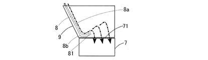
- the fallen cutting tapes 33 a and 34 a slide down the inclined surface 8 a of the slope member 8 diagonally downward and jump upward diagonally upward at the warped portion 81. As shown by the one-dot chain line in FIG. As a result, the cutting tapes 33 a and 34 a are accommodated in the box 7 in a distributed manner in the drawing direction of the box 7.
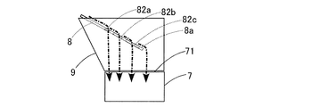
- the inclined surface 8a of the slope member 8 formed in a rectangular plate shape is provided with an inclined surface 8a as an opening of the box 7 as a second form of cutting tape dispersing means for dispersing the cutting tapes 33a and 34a in the box 7.
- 82a, 82b, and 82c are provided.
- the hole located in the upward direction of the slope member 8 has a smaller diameter than the hole located in the downward direction of the slope member 8, that is, the hole 82a has a smaller diameter than the hole 82b, and the hole 82b has a smaller diameter than the hole 82c. It is formed.
- the cutting tapes 33 a and 34 a respectively cut by the blade member 61 are released from the holding of the pressing member 62 and the pressing receiving member 65 by the operation of the air cylinder 63 and fall.
- the dropped cutting tapes 33a and 34a slide down obliquely downward on the inclined surface 8a of the slope member 8.
- the length of the cutting tape 33a, 34a falls through the holes 82a, 82b, 82c.
- the cutting tapes 33a and 34a the cutting length larger than the diameter of the hole 82c falls from the lower edge 8b of the slope member 8 without falling at the holes 82a, 82b and 82c.
- the cutting tapes 33a and 34a are distributed and accommodated in the box 7 in order from the one with the smallest cutting length in the drawing direction of the box 7.
- the inclined surface 8a of the slope member 8 is provided with holes 82a, 82b and 82c, and the lower end edge portion 8b of the slope member 8 is formed with a warped portion 81 so that the cutting tapes 33a and 34a are attached to the box. 7 can be distributed in a uniform manner in the direction in which the box 7 is pulled out.
- the slope member 8 includes a box 7 centered on the upper edge 8c of the slope member 8 as a third form of cutting tape dispersing means for dispersing the cutting tapes 33a and 34a in the box 7.
- the swing mechanism 83 is configured to be interlocked with the air cylinder 63 (cutting mechanism) of the cutter 6 and includes an arm member 831, a rotating member 832, and the like. Since the swing mechanism 83 does not require a unique power source, it can be configured simply.
- the arm member 831 is formed in a substantially L shape, a claw member 831a is provided at the tip, the rear end is fixed to the blade member 61, and reciprocates in the Y direction together with the blade member 61.
- the rotating member 832 is formed in a disk shape, and the center thereof is connected to a rotating shaft 8d provided along the upper end edge 8c of the slope member 8 via a speed reduction mechanism (not shown).
- a claw portion 832a that can be locked to the claw member 831a is formed in a cross shape on the end surface of the rotating member 832.
- the rotation member 832 includes a ratchet mechanism (not shown) that prevents the rotation member 832 from rotating clockwise in FIG. 4A and a ratchet release mechanism (not shown) that releases the rotation prevention by the ratchet mechanism.
- the claw member 831 a of the arm member 831 is locked to the claw portion 832 a of the rotation member 832, and the rotation member 832 is rotated 45 degrees counterclockwise in FIG. 4A.
- the claw member 831a of the arm member 831 causes the slope member 8 to be initialized by one reciprocation of the arm member 831 accompanying one reciprocation of the blade member 61 for cutting the tape. Rotate ⁇ degrees counterclockwise from the state. This rotation of ⁇ degrees is maintained by a ratchet mechanism. Then, the cutting tapes 33a and 34a cut and dropped respectively by the blade member 61 slide down the inclined surface 8a of the slope member 8 obliquely downward, and the box 7 is shifted to the drawing direction side of the box 7 from the loading position in the initial state. It is thrown in the position. This operation is performed until the slope member 8 is rotated 3 ⁇ degrees counterclockwise from the initial state.
- the claw member 831a of the arm member 831 rotates the slope member 8 counterclockwise from the initial state to 3 ⁇ degrees
- the claw member 831a of the arm member 831 is moved by the operation for cutting the tape of the blade member 61.
- the ratchet release mechanism is separated from the claw portion 832a of the rotation member 832, the ratchet release mechanism releases the rotation prevention by the ratchet mechanism.
- the slope member 8 rotates 3 ⁇ degrees clockwise as shown in FIG. 4C and returns to the initial state.
- the slope member 8 swings, so that the cutting tapes 33a and 34a are inserted into the box 7 at swing angles (0 degrees, ⁇ degrees, 2 ⁇ degrees, 3 ⁇ degrees). The position is shifted to the drawing direction side of the box 7, and the boxes 7 are distributed and accommodated in the drawing direction of the box 7.
- the lower end edge portion 8b of the slope member 8 may be formed with a warped portion 81, the inclined surface 8a of the slope member 8 may be provided with holes 82a, 82b, 82c, While forming the curvature part 81, you may provide each hole 82a, 82b, 82c.
- the cutting tapes 33 a and 34 a can be accommodated in the box 7 while being uniformly distributed in the drawing direction of the box 7.
- FIGS. 5A and 5B a fourth embodiment of the cutting tape dispersing means will be described with reference to FIGS. 5A and 5B.
- this 4th form is applied to the thing provided with the rocking
- the fourth form of the cutting tape dispersing means for dispersing the cutting tapes 33 a and 34 a in the box 7 the crests of the cutting tapes 33 a and 34 a introduced into the box 7 are formed on the lower edge 8 b of the slope member 8.
- a leveling member 84 for leveling is provided.
- the rotating member 832 attached to the rotating shaft 8d of the slope member 8 is provided with a pulling mechanism 10 that pulls the slope member 8 in the pulling direction of the box 7 and moves the leveling member 84 above the recovery port 11a. .
- the leveling member 84 is formed in a rectangular plate shape having substantially the same width as the slope member 8, and the upper end edge 84 a of the leveling member 84 and the lower end edge 8 b of the slope member 8 are fixed to each other. That is, the leveling member 84 is provided to swing within the box 7 when the slope member 8 is swinging.
- the pulling mechanism 10 includes a wire 10a, a pulley 10b, and a pedal 10c. The wire 10a is hung on the pulley 10b, and one end is locked to the outer periphery of the rotating member 832 and the other end is locked to the pedal 10c.
- the slope member 8 is swung.
- the leveling member 84 is swung in the box 7 and cut in a crest in the box 7. Since it contacts the tapes 33a, 34a, the crests of the cutting tapes 33a, 34a can be leveled.
- the cutting tapes 33 a and 34 a are accommodated in the box 7 in a distributed manner in the drawing direction of the box 7.
- the operator pulls out the box 7 in order to collect the cutting tapes 33a and 34a accumulated in the box 7, the operator steps on the pedal 10c and pulls the slope member 8 in the pulling direction of the box 7 to equalize the member 84. Is moved upward from the recovery port 11a (a state indicated by a one-dot chain line in FIG. 5A). Thereby, since the leveling member 84 does not interfere with the box 7, the box 7 can be pulled out easily.
- the slope member 8 moved upward by the pulling mechanism 10 is stopped at the upper position by the ratchet mechanism. Then, when the operator depresses the pedal 10c again, the stop state of the slope member 8 by the ratchet mechanism is released, and the slope member 8 returns to the initial state.
- the inclined surface 8a of the slope member 8 may be provided with holes 82a, 82b, 82c. As a result, the cutting tapes 33 a and 34 a can be accommodated in the box 7 while being uniformly distributed in the drawing direction of the box 7.
- the mixing member 85 is formed in a J-shape, and the upper end edges 85 a of the plurality of mixing members 85 are fixed to the lower end edge 8 b of the slope member 8 at a predetermined interval, and the lower end edges 85 b are near the bottom surface of the box 7. It is provided so that it may extend.
- the slope member 8 is swung.
- the mixing member 85 is swung in the cutting tapes 33a and 34a accumulated in the box 7,
- the cutting tapes 33a and 34a accumulated in the box 7 can be scraped and mixed.
- the tip of the mixing member 85 is bent in a J shape, the cutting tapes 33a and 34a can be hooked and mixed.
- the cutting tapes 33 a and 34 a are accommodated in the box 7 in a distributed manner in the drawing direction of the box 7.
- the slope member 8 moved upward by the pulling mechanism 10 is stopped at the upper position by the ratchet mechanism. Then, when the operator depresses the pedal 10c again, the stop state of the slope member 8 by the ratchet mechanism is released, and the slope member 8 returns to the initial state.
- the inclined surface 8a of the slope member 8 may be provided with holes 82a, 82b, 82c. As a result, the cutting tapes 33 a and 34 a can be accommodated in the box 7 while being uniformly distributed in the drawing direction of the box 7.
- the component mounting machine 1 is provided with a cutter 6 that cuts the tapes 33 and 34 from which the component P is collected, and is provided below the cutter 6 so as to be able to be pulled out from the collection port 11a of the mounting machine body 11.
- the opening 71 is formed from the lower side of the cutter 6 toward the recovery port 11a, and the cutting tapes 33a and 34a which are cut by the cutter 6 and dropped are collected from the opening 71 and the lower side of the cutter 6.
- a slope member 8 that is inclined to the opening 11a so as to incline at the depression angle and reach the opening 71, and slides the cutting tapes 33a and 34a toward the opening 71 by the inclined surface 8a, and slides down the inclined surface 8a.
- the cutting tape dispersing means is a warped portion 81 formed so as to bend at the lower end edge portion 8b of the slope member 8 at an elevation angle. According to this, since the cutting length and the weight of the cutting tapes 33a and 34a vary depending on the type of the part P, the flying distance from the warped portion 81 changes. Be contained.
- the cutting tape dispersing means is holes 82a, 82b, 82c provided in the inclined surface 8a. According to this, since the cutting lengths of the cutting tapes 33a and 34a differ depending on the type of the part P, the cutting tapes 33a and 34a having a length smaller than the diameters of the holes 82a, 82b and 82c are the holes 82a, 82b and 82c. Since it falls through the box 7, it is accommodated in the box 7 in a distributed manner in the direction in which the box 7 is pulled out.
- At least two holes 82a, 82b, and 82c are provided in the inclination direction of the slope member 8, and the diameter of the hole located in the upward direction of the slope member 8 is smaller than the diameter of the hole located in the downward direction of the slope member 8.
- the cutting tapes 33a and 34a are distributed and accommodated in the box 7 in order from the one with the smallest cutting length in the drawing direction of the box 7.
- the cutting tape dispersing means is a swing mechanism 83 that swings the slope member 8 in the pull-out direction around the upper edge 8c of the slope member 8. According to this, the cutting tapes 33 a and 34 a are accommodated in the box 7 in a distributed manner in the pulling-out direction of the box 7 because the insertion position into the box 7 is shifted to the pulling-out direction side of the box 7 depending on the swing angle.
- the cutting tape dispersing means is a leveling member 84 for leveling the peaks of the cutting tapes 33a and 34a in the box 7 provided at the lower end edge 8b of the slope member 8. According to this, since the leveling member 84 swings in the box 7, it is possible to level the cutting tapes 33 a and 34 a that are crested in the box 7, and the cutting tapes 33 a and 34 a Are distributed and accommodated in the direction in which the box 7 is pulled out.
- the cutting tape dispersing means is a mixing member 85 that mixes the cutting tapes 33 a and 34 a in the box 7 provided at the lower end edge 8 b of the slope member 8. According to this, since the mixing member 85 swings in the cutting tapes 33a and 34a accumulated in the box 7, the cutting tapes 33a and 34a accumulated in the box 7 can be scraped and mixed, and the cutting tape 33a , 34a are accommodated in the box 7 in a distributed manner in the direction in which the box 7 is pulled out.
- the slope member 8 is provided with a pulling mechanism 10 that pulls the slope member 8 in the pulling direction and moves it upward from the recovery port 11a. According to this, since the leveling member 84 and the mixing member 85 do not interfere with the box 7, the box 7 can be pulled out easily.
- the swing mechanism 83 is configured to be interlocked with the air cylinder 63 that performs the cutting operation of the cutter 6. According to this, since the swing mechanism 83 does not require a unique power source, it can have a simple configuration. (Other)
- the warped portion 81 is formed on the entire lower end edge portion 8b of the slope member 8, but may be formed partially on the lower end edge portion 8b of the slope member 8. Further, the size and number of the holes 82a, 82b, 82c provided in the inclined surface 8a of the slope member 8 are such that the holes positioned in the inclined upward direction of the slope member 8 are different from the holes positioned in the inclined downward direction of the slope member 8. May be formed in a small diameter, and may be formed in any size and number.
- the swing angle and the angle to return to the initial state may be set to arbitrary angles.
- the leveling member 84 is formed in a rectangular plate shape having substantially the same width as the width of the slope member 8, but may be formed in a rectangular plate shape having a width smaller than the width of the slope member 8.
- the plurality of leveling members 84 may be fixed to the lower edge portion 8b of the slope member 8 with a space therebetween.
- the shape and number of the mixing members 85 may be any shape and number as long as they can swing within the cutting tapes 33a and 34a accumulated in the box 7.
- the mechanism for pulling the wire 10a with the pedal 10c via the pulley 10b as the pulling mechanism 10 for pulling the slope member 8 in the pulling direction has been described as an example.
- the present invention is not limited thereto. It is good also as a mechanism which pulls the wire 10a with a motor.
- the air cylinder 63 has been described as an example of the cutting mechanism that performs the cutting operation of the cutter 6.
- the present invention is not limited to this.
- the cutting mechanism is configured by a motor and a gear mechanism. Also good.
- the component mounter of the present invention is applicable when processing a tape in which components are stored.
Landscapes
- Engineering & Computer Science (AREA)
- Manufacturing & Machinery (AREA)
- Microelectronics & Electronic Packaging (AREA)
- Supply And Installment Of Electrical Components (AREA)
Abstract
部品実装機1は、傾斜面8aを滑落する切断テープ33a,34aを引き出し方向に分散して開口部71からボックス7に収容させる切断テープ分散手段81,82a,82b,82c,83,84,85を設けたスロープ部材8を備える。これによれば、切断テープ分散手段81,82a,82b,82c,83,84,85は、スロープ部材8に設けられるので、切断テープ33a,34aが大量に発生しても当該切断テープ33a,34aをボックス7内においてボックス7の引き出し方向に均一に分散させて収容できる。
Description
本発明は、部品供給装置から供給されるテープに収容された部品を部品移載装置で採取し基板搬送装置で搬送される基板上に装着する部品実装機に関する。
部品が採取されたテープは、カッタで切断されてボックス内に収容されるが、収容された切断テープは、ボックス内の特定位置に山になって溜まり易いという問題がある。そこで、例えば、特許文献1には、テープを切断するカッタと、切断テープを収容するボックスと、切断テープをボックスに導くスロープ部材と、ボックスを水平方向に往復動作させる機構とを備えた部品実装機が記載されている。ボックスが、水平方向に往復動作することにより、ボックス内の切断テープは、ボックスの動作方向に移動するので、ボックス内の切断テープは、特定位置に溜まらずに分散する。
上述の部品実装機では、ボックスを移動させる大型の機構を備える必要があるため、部品実装機自体が大型化する傾向にある。また、ボックス内の切断テープは、徐々に移動するため、基板を高速で生産する場合は大量に発生する切断テープに対して対応が遅れ、ボックス内の特定位置に山になって溜まってしまうという問題がある。
本発明は上記事情に鑑みてなされたものであり、その目的は、簡易な構造でボックス内に収容する切断テープを確実に分散できる部品実装機を提供することにある。
本発明は上記事情に鑑みてなされたものであり、その目的は、簡易な構造でボックス内に収容する切断テープを確実に分散できる部品実装機を提供することにある。
上述した課題を解決するために、本発明は、部品供給装置から供給されるテープに収容された部品を部品移載装置で採取し基板搬送装置で搬送される基板上に装着する部品実装機において、前記部品が採取された前記テープを切断するカッタと、前記カッタの下方において実装機本体の回収口から引き出し可能に設けられ、上方に開口する開口部が前記カッタの下方から前記回収口に向かって形成され、前記カッタで切断されて落下する切断テープが前記開口部から投入されるボックスと、前記カッタの下方から前記回収口側に伏角で傾斜し前記開口部に至るように設けられ、前記切断テープを傾斜面で前記開口部に向けて滑落させるスロープ部材と、を備え、前記傾斜面を滑落する前記切断テープを前記引き出し方向に分散して前記開口部から前記ボックスに収容させる切断テープ分散手段を前記スロープ部材に設ける。
本発明の切断テープ分散手段は、スロープ部材に設けられるので、簡単な構造として部品実装機の大型化を回避できる。また、切断テープが大量に発生しても当該切断テープをボックス内においてボックスの引き出し方向に均一に分散させて収容できる。
(部品実装機の概略構成)
以下、本発明の部品実装機の実施の形態を図面に基づいて説明する。なお、図1において、基板PBの搬送方向をX方向(紙面に垂直な方向)、X方向と直交する水平方向をY方向、X方向と直交する垂直方向をZ方向とする。
以下、本発明の部品実装機の実施の形態を図面に基づいて説明する。なお、図1において、基板PBの搬送方向をX方向(紙面に垂直な方向)、X方向と直交する水平方向をY方向、X方向と直交する垂直方向をZ方向とする。
図1に示すように、本実施形態による部品実装機1は、実装機本体として基台11の上面の奥側(図1の左側)に配設され、基板PBを搬送して部品実装位置に搬入出する基板搬送装置2と、基台11の上面の手前側(図1の右側)に配設され、基板PB上に装着する部品Pを供給する部品供給装置3と、基台11の上面の上方に配設され、基板PB上に装着する部品Pを吸着して移載する部品移載装置4と、部品供給装置3の下方に配設され、後述する部品Pが収納されたキャリアテープ34及びトップテープ33を部品Pの吸着後に処理するテープ処理装置5等とを備える。
基板搬送装置2は、一対のガイドレール21a,21bと、一対のコンベアベルト22a,22bと、クランプ装置23等とを備える。一対のガイドレール21a,21bは、X方向に延在し基板PBの幅と略同一の距離を隔てて互いに平行に配置される。一対のコンベアベルト22a,22bは、ガイドレール21a,21bの直下に並設される。クランプ装置23は、一対のガイドレール21a,21bの間であって実装位置の下方に配設される。
このような構成の基板搬送装置2においては、基板PBが、一対のガイドレール21a,21bによりX方向に案内されつつ一対のコンベアベルト22a,22bにより部品実装位置まで搬送され、クランプ装置23によりコンベアベルト22a,22bから押し上げられてクランプされ位置決め固定される。
部品供給装置3は、異なる部品種の部品Pを夫々収容して供給する複数のカセット式のフィーダ31がX方向に沿ってセットされる。フィーダ31は、後部に部品供給リール32がセットされるフィーダ本体31aと、該フィーダ本体31aの前部に設けられた部品取出し箇所31bとにより概略構成される。部品供給リール32には、部品Pが所定ピッチで配置されトップテープ33で覆われたキャリアテープ34が巻回される。
このような構成の部品供給装置3においては、キャリアテープ34がフィーダ本体31aに備えられたスプロケット(図示省略)により所定ピッチで引き出され、トップテープ33が引き剥がされ、部品Pが部品取出し箇所31bに順次送り込まれる。そして、部品Pが吸着された後のトップテープ33及びキャリアテープ34は、テープ処理装置5に送り込まれる。
部品移載装置4は、駆動装置40によって水平面内で移動されるヘッドホルダ41等を備える。駆動装置40は、一対の固定レール42a,42bと、ヘッド移動レール43等とを備える。一対の固定レール42a,42bは、基板搬送装置2の両端部の上方にY方向に延在し互いに平行に配置される。ヘッド移動レール43は、X方向に延在して配置されて両端が固定レール42a,42bに沿って移動可能に支持される。ヘッド移動レール43は、ボールねじを介してサーボモータ(いずれも図示省略)により移動制御可能に構成される。
ヘッドホルダ41は、ヘッド移動レール43に沿って移動可能に支持される。ヘッドホルダ41は、ボールねじを介してサーボモータ(いずれも図示省略)により移動制御可能に構成される。ヘッドホルダ41には、基板PBにおける部品装着位置の認識が可能な認識用カメラ44及びZ軸回りを回転可能且つZ方向に昇降可能な実装ヘッド45が保持される。この実装ヘッド45には、部品Pを吸着する部品吸着ノズル46を着脱可能に保持するノズルホルダ47が、実装ヘッド45の回転中心において下方に突設される。
部品吸着ノズル46が装着されたノズルホルダ47は、実装ヘッド45からZ方向に昇降可能に且つZ軸回りで回転可能に支持される。部品吸着ノズル46が装着されたノズルホルダ47は、ボールねじを介してサーボモータ(いずれも図示省略)により昇降制御可能、且つギヤ機構を介してサーボモータ(いずれも図示省略)により回転制御可能に構成される。部品吸着ノズル46は、略中空円筒状に形成され大気圧、正圧、負圧の切換可能な三方向バルブを介して真空ポンプ(図示省略)と接続され、ノズル下端において部品Pを吸着保持可能に構成される。また、部品移載装置4と部品供給装置3の間には、部品吸着ノズル46の部品Pの吸着状態の認識が可能な部品認識用カメラ48が取り付けられる。
このような構成の部品移載装置4においては、フィーダ31の部品取出し箇所31bに供給された部品Pが、部品吸着ノズル46により吸着されヘッド移動レール43及びヘッドホルダ41により部品実装位置に位置決めされた基板PBまで移送され、部品吸着ノズル46により基板PB上の部品装着位置に装着される。
テープ処理装置5は、フィーダ31の下方に配設され、部品Pが吸着されたキャリアテープ34及びトップテープ33を切断するカッタ6と、カッタ6の下方に配設され、切断されたキャリアテープ34a及びトップテープ33a(以下、単に切断テープ33a,34aという)が投入されるボックス7と、カッタ6とボックス7との間に配設され、切断テープ33a,34aを傾斜面8aで滑落させるスロープ部材8と、カッタ6とボックス7との間にスロープ部材8を覆うように配設されるカバー部材9等とを備える。
カッタ6は、刃先がY方向を向くように配置された刃部材61と、刃部材61の下方に隣接して設けられた押圧部材62と、刃部材61をY方向に移動させる切断機構としてエアーシリンダ63と、軸線方向がY方向を向くように配置され、押圧部材62に一端が取着され、刃部材61に他端が取着された押圧バネ64と、押圧部材62とY方向に所定間隔をあけて対向配置された押圧受け部材65等とを備える。刃部材61等は、上部にトップテープ33及びキャリアテープ34の導入口66aが形成された筺体66に内蔵される。
刃部材61は、幅広の片刃であり、押圧部材62と押圧受け部材65とに挟持されたトップテープ33及びキャリアテープ34を所定長で切断するために、Y方向に移動可能に設けられる。押圧部材62は、刃部材61の幅より若干広い幅を有する板状部材であり、トップテープ33及びキャリアテープ34を押圧して押圧受け部材65と挟持するために、Y方向に移動可能に設けられる。押圧バネ64は、圧縮バネであり、刃部材61の移動に伴い押圧受け部材65及び押圧部材62で挟持したトップテープ33及びキャリアテープ34を押圧可能に設けられる。
ボックス7は、中空の直方体状に形成され、基台11の前面下方に設けられた回収口11aから水平方向に引き出し可能に設けられる。ボックス7には、上方に開口する開口部71がカッタ6の下方から回収口11aに向かって形成される。ボックス7の内側上部には、ボックス7内に堆積した切断テープ33a,34aが一定量以上溜ったことを検知する図略のセンサが取り付けられる。また、ボックス7の前面には、切断テープ33a,34aの収容度合いの視認を可能とするため、透明材でなる図略の窓が形成される。
スロープ部材8は、矩形板状に形成され、カッタ6の下方から回収口11aに伏角で傾斜しボックス7の開口部71に至るように設けられる。スロープ部材8の下端縁部8bには、ボックス7内において切断テープ33a,34aを分散させるための切断テープ分散手段の第一形態として、傾斜面8aをボックス7の開口部71に向けて滑落してきた切断テープ33a,34aを跳躍させる仰角で反る反り部81が形成される。すなわち、スロープ部材8の下端縁部8bは、下に凸の湾曲状に形成される。
カバー部材9は、切断テープ33a,34aが反り部81で跳躍し過ぎてボックス7外へ飛び出してしまうことを防止するため、ボックス7の開口部71の周縁部から上方に延びるダクト状に形成される。
このような構成のテープ処理装置5においては、押圧部材62と押圧受け部材65との間に送り込まれたトップテープ33及びキャリアテープ34が、エアーシリンダ63の動作により押圧部材62及び押圧受け部材65で挟持され、刃部材61によりそれぞれ切断される。そして、切断テープ33a,34aは、エアーシリンダ63の動作により押圧部材62及び押圧受け部材65の挟持から解放され落下する。
落下した切断テープ33a,34aは、スロープ部材8の傾斜面8aを斜め下方に滑落し、反り部81で斜め上方に跳躍する。図2の一点鎖線で示すように、切断テープ33a,34aは、部品Pの種類によって切断長や重量が異なるため、反り部81からの飛距離が変化する。これにより、切断テープ33a,34aは、ボックス7内においてボックス7の引き出し方向に分散して収容されることになる。
(第二形態の切断テープ分散手段の概略構成)
次に、切断テープ分散手段の第二形態について、図3A及び図3Bを参照して説明する。矩形板状に形成されたスロープ部材8の傾斜面8aには、ボックス7内において切断テープ33a,34aを分散させるための切断テープ分散手段の第二形態として、傾斜面8aをボックス7の開口部71に向けて滑落してきた切断テープ33a,34aを傾斜面8aの途中で落下させる異径(本例では、3つの異なる径)の複数(本例では、3個ずつの合計9個)の穴82a,82b,82cが設けられる。スロープ部材8の傾斜上方向に位置する穴は、スロープ部材8の傾斜下方向に位置する穴よりも小径に形成、すなわち穴82aは穴82bより小径に形成され、穴82bは穴82cより小径に形成される。
次に、切断テープ分散手段の第二形態について、図3A及び図3Bを参照して説明する。矩形板状に形成されたスロープ部材8の傾斜面8aには、ボックス7内において切断テープ33a,34aを分散させるための切断テープ分散手段の第二形態として、傾斜面8aをボックス7の開口部71に向けて滑落してきた切断テープ33a,34aを傾斜面8aの途中で落下させる異径(本例では、3つの異なる径)の複数(本例では、3個ずつの合計9個)の穴82a,82b,82cが設けられる。スロープ部材8の傾斜上方向に位置する穴は、スロープ部材8の傾斜下方向に位置する穴よりも小径に形成、すなわち穴82aは穴82bより小径に形成され、穴82bは穴82cより小径に形成される。
このような構成においては、刃部材61によりそれぞれ切断された切断テープ33a,34aは、エアーシリンダ63の動作により押圧部材62及び押圧受け部材65の挟持から解放され落下する。図3Aの一点鎖線で示すように、落下した切断テープ33a,34aは、スロープ部材8の傾斜面8aを斜め下方に滑落するが、部品Pの種類によって切断長が異なるため、各穴82a,82b,82cの径より小さい長さの切断テープ33a,34aが各穴82a,82b,82cを通って落下する。
そして、切断テープ33a,34aのうち、切断長が穴82cの径より大きいものは、各穴82a,82b,82cで落下せずにスロープ部材8の下端縁部8bから落下ずる。これにより、切断テープ33a,34aは、ボックス7内においてボックス7の引き出し方向に切断長が小さいものから順に分散して収容されることになる。なお、スロープ部材8の傾斜面8aには、各穴82a,82b,82cを設けると共に、スロープ部材8の下端縁部8bには、反り部81を形成することにより、切断テープ33a,34aをボックス7内においてボックス7の引き出し方向により均一に分散させて収容できる。
(第三形態の切断テープ分散手段の概略構成)
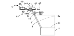
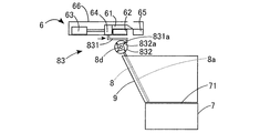
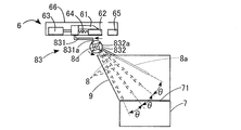
次に、切断テープ分散手段の第三形態について、図4A,図4B及び図4Cを参照して説明する。図4Aに示すように、スロープ部材8には、ボックス7内において切断テープ33a,34aを分散させるための切断テープ分散手段の第三形態として、スロープ部材8の上端縁部8cを中心にボックス7の引き出し方向にスロープ部材8を揺動させる揺動機構83が備えられる。この揺動機構83は、カッタ6のエアーシリンダ63(切断機構)と連動するように構成され、アーム部材831と、回転部材832等とを備える。揺動機構83は、独自の動力源を必要としないので、簡易な構成とすることができる。
次に、切断テープ分散手段の第三形態について、図4A,図4B及び図4Cを参照して説明する。図4Aに示すように、スロープ部材8には、ボックス7内において切断テープ33a,34aを分散させるための切断テープ分散手段の第三形態として、スロープ部材8の上端縁部8cを中心にボックス7の引き出し方向にスロープ部材8を揺動させる揺動機構83が備えられる。この揺動機構83は、カッタ6のエアーシリンダ63(切断機構)と連動するように構成され、アーム部材831と、回転部材832等とを備える。揺動機構83は、独自の動力源を必要としないので、簡易な構成とすることができる。
アーム部材831は、略L字状に形成され、先端に爪部材831aが設けられ、後端が刃部材61に固定され、刃部材61と共にY方向に往復移動する。回転部材832は、円盤状に形成され、中心がスロープ部材8の上端縁部8cに沿って設けられた回転軸8dに図略の減速機構を介して連結される。回転部材832の端面には、爪部材831aに係止可能な爪部832aが十字状に形成される。回転部材832には、回転部材832の図4Aの時計回りの回転を防止する図略のラチェット機構及びラチェット機構による回転防止を解除する図略のラチェット解除機構が内蔵される。
このような構成においては、アーム部材831の一往復動作により、アーム部材831の爪部材831aが、回転部材832の爪部832aに係止して回転部材832を図4Aの反時計回りに45度回転させ、減速機構によりスロープ部材8(回転軸8d)を図4Aの反時計回りにθ度回転させる。すなわち、図4Aに示す初期状態においては、スロープ部材8は、最も傾斜した位置(θ度=0度とする)に位置している。そして、刃部材61によりそれぞれ切断され落下した切断テープ33a,34aは、スロープ部材8の傾斜面8aを斜め下方に滑落し、ボックス7内に投入される。
続いて、図4B及び図4Cに示すように、刃部材61のテープ切断のための一往復動作に伴うアーム部材831の一往復動作により、アーム部材831の爪部材831aが、スロープ部材8を初期状態から反時計回りにθ度回転させる。このθ度の回転は、ラチェット機構により維持される。そして、刃部材61によりそれぞれ切断され落下した切断テープ33a,34aは、スロープ部材8の傾斜面8aを斜め下方に滑落し、初期状態における投入位置よりもボックス7の引き出し方向側にずれたボックス7内の位置に投入される。この動作は、スロープ部材8を初期状態から反時計回りに3θ度回転させるまで行われる。
そして、アーム部材831の爪部材831aが、スロープ部材8を初期状態から反時計回りに3θ度まで回転させた後、刃部材61のテープ切断のための動作により、アーム部材831の爪部材831aが、回転部材832の爪部832aから離間したら、ラチェット解除機構は、ラチェット機構による回転防止を解除する。これにより、スロープ部材8は、図4Cに示す時計回りに3θ度回転して初期状態に戻る。以上の動作を繰り返すことにより、スロープ部材8は、揺動することになるので、切断テープ33a,34aは、揺動角度(0度、θ度、2θ度、3θ度)によってボックス7への投入位置がボックス7の引き出し方向側にずれ、ボックス7内においてボックス7の引き出し方向に分散して収容されることになる。
なお、スロープ部材8の下端縁部8bには、反り部81を形成してもよく、また、スロープ部材8の傾斜面8aには、各穴82a,82b,82cを設けてもよく、また、反り部81を形成するとともに各穴82a,82b,82cを設けてもよい。これにより、切断テープ33a,34aをボックス7内においてボックス7の引き出し方向により均一に分散させて収容できる。
(第四形態の切断テープ分散手段の概略構成)
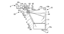
次に、切断テープ分散手段の第四形態について、図5A及び図5Bを参照して説明する。なお、この第四の形態は、第三の形態で説明した揺動機構83を備えたものに適用される。スロープ部材8の下端縁部8bには、ボックス7内において切断テープ33a,34aを分散させるための切断テープ分散手段の第四形態として、ボックス7内に投入された切断テープ33a,34aの山を均す均し部材84が設けられる。さらに、スロープ部材8の回転軸8dに取り付けられた回転部材832には、スロープ部材8をボックス7の引き出し方向に引っ張って均し部材84を回収口11aより上方に移動させる引っ張り機構10が設けられる。
次に、切断テープ分散手段の第四形態について、図5A及び図5Bを参照して説明する。なお、この第四の形態は、第三の形態で説明した揺動機構83を備えたものに適用される。スロープ部材8の下端縁部8bには、ボックス7内において切断テープ33a,34aを分散させるための切断テープ分散手段の第四形態として、ボックス7内に投入された切断テープ33a,34aの山を均す均し部材84が設けられる。さらに、スロープ部材8の回転軸8dに取り付けられた回転部材832には、スロープ部材8をボックス7の引き出し方向に引っ張って均し部材84を回収口11aより上方に移動させる引っ張り機構10が設けられる。
均し部材84は、スロープ部材8の幅と略同一幅の矩形板状に形成され、均し部材84の上端縁部84aとスロープ部材8の下端縁部8bとが固着される。すなわち、均し部材84は、スロープ部材8が揺動しているときは、ボックス7内で揺動するように設けられる。引っ張り機構10は、ワイヤ10aと、滑車10bと、ペダル10cとを備える。ワイヤ10aは、滑車10bに掛けられ、一端が回転部材832の外周に係止され、他端がペダル10cに係止される。
このような構成においては、第三形態で説明したように、スロープ部材8を揺動させるが、このとき均し部材84は、ボックス7内で揺動してボックス7内で山になった切断テープ33a,34aに接触するので、切断テープ33a,34aの山を均すことができる。これにより、切断テープ33a,34aは、ボックス7内においてボックス7の引き出し方向に分散して収容されることになる。そして、作業者は、ボックス7内に溜まった切断テープ33a,34aを回収するためにボックス7を引き出すときは、ペダル10cを踏み、スロープ部材8をボックス7の引き出し方向に引っ張って均し部材84を回収口11aより上方に移動させる(図5Aの一点鎖線で示す状態)。これにより、均し部材84は、ボックス7と干渉しないので、ボックス7を容易に引き出すことができる。
引っ張り機構10で上方に移動したスロープ部材8は、ラチェット機構により上方位置で停止している。そして、作業者が、ペダル10cを再度踏み込むことで、ラチェット機構によるスロープ部材8の停止状態が解除され、スロープ部材8は、初期状態に戻るようになっている。なお、スロープ部材8の傾斜面8aには、各穴82a,82b,82cを設けてもよい。これにより、切断テープ33a,34aをボックス7内においてボックス7の引き出し方向により均一に分散させて収容できる。
(第五形態の切断テープ分散手段の概略構成)
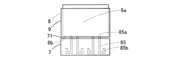
次に、切断テープ分散手段の第五形態について、図6A及び図6Bを参照して説明する。なお、この第五形態は、第四形態で説明した揺動機構83及び引っ張り機構10を備えたものに適用される。スロープ部材8の下端縁部8bには、ボックス7内において切断テープ33a,34aを分散させるための切断テープ分散手段の第五形態として、ボックス7内に投入された切断テープ33a,34aを混ぜる混ぜ部材85が設けられる。混ぜ部材85は、J字状に形成され、複数の混ぜ部材85の上端縁部85aが所定間隔をあけてスロープ部材8の下端縁部8bに固着され、下端縁部85bがボックス7の底面近傍まで延びるように設けられる。
次に、切断テープ分散手段の第五形態について、図6A及び図6Bを参照して説明する。なお、この第五形態は、第四形態で説明した揺動機構83及び引っ張り機構10を備えたものに適用される。スロープ部材8の下端縁部8bには、ボックス7内において切断テープ33a,34aを分散させるための切断テープ分散手段の第五形態として、ボックス7内に投入された切断テープ33a,34aを混ぜる混ぜ部材85が設けられる。混ぜ部材85は、J字状に形成され、複数の混ぜ部材85の上端縁部85aが所定間隔をあけてスロープ部材8の下端縁部8bに固着され、下端縁部85bがボックス7の底面近傍まで延びるように設けられる。
このような構成においては、第四形態で説明したように、スロープ部材8を揺動させるが、このとき混ぜ部材85は、ボックス7内に溜まった切断テープ33a,34a内で揺動するので、ボックス7内に溜まった切断テープ33a,34aを掻き分けて混ぜることができる。特に、混ぜ部材85の先端部は、J字状に曲がっているので、切断テープ33a,34aを引っ掛けて混ぜることができる。これにより、切断テープ33a,34aは、ボックス7内においてボックス7の引き出し方向に分散して収容されることになる。そして、作業者は、ボックス7内に溜まった切断テープ33a,34aを回収するためにボックス7を引き出すときは、ペダル10cを踏み、スロープ部材8をボックス7の引き出し方向に引っ張って混ぜ部材85を回収口11aより上方に移動させる(図6Aの一点鎖線で示す状態)。これにより、混ぜ部材85は、ボックス7と干渉しないので、ボックス7を容易に引き出すことができる。
引っ張り機構10で上方に移動したスロープ部材8は、ラチェット機構により上方位置で停止している。そして、作業者が、ペダル10cを再度踏み込むことで、ラチェット機構によるスロープ部材8の停止状態が解除され、スロープ部材8は、初期状態に戻るようになっている。なお、スロープ部材8の傾斜面8aには、各穴82a,82b,82cを設けてもよい。これにより、切断テープ33a,34aをボックス7内においてボックス7の引き出し方向により均一に分散させて収容できる。
(実施形態の効果)
本実施形態の部品実装機1は、部品Pが採取されたテープ33,34を切断するカッタ6と、カッタ6の下方において実装機本体11の回収口11aから引き出し可能に設けられ、上方に開口する開口部71がカッタ6の下方から回収口11aに向かって形成され、カッタ6で切断されて落下する切断テープ33a,34aが開口部71から投入されるボックス7と、カッタ6の下方から回収口11a側に伏角で傾斜し開口部71に至るように設けられ、切断テープ33a,34aを傾斜面8aで開口部71に向けて滑落させるスロープ部材8と、を備え、傾斜面8aを滑落する切断テープ33a,34aを引き出し方向に分散して開口部71からボックス7に収容させる切断テープ分散手段81,82a,82b,82c,83,84,85をスロープ部材8に設ける。これによれば、切断テープ分散手段81,82a,82b,82c,83,84,85は、スロープ部材8に設けられるので、簡単な構造として部品実装機の大型化を回避できる。また、切断テープ33a,34aが大量に発生しても当該切断テープ33a,34aをボックス7内においてボックス7の引き出し方向に均一に分散させて収容できる。
本実施形態の部品実装機1は、部品Pが採取されたテープ33,34を切断するカッタ6と、カッタ6の下方において実装機本体11の回収口11aから引き出し可能に設けられ、上方に開口する開口部71がカッタ6の下方から回収口11aに向かって形成され、カッタ6で切断されて落下する切断テープ33a,34aが開口部71から投入されるボックス7と、カッタ6の下方から回収口11a側に伏角で傾斜し開口部71に至るように設けられ、切断テープ33a,34aを傾斜面8aで開口部71に向けて滑落させるスロープ部材8と、を備え、傾斜面8aを滑落する切断テープ33a,34aを引き出し方向に分散して開口部71からボックス7に収容させる切断テープ分散手段81,82a,82b,82c,83,84,85をスロープ部材8に設ける。これによれば、切断テープ分散手段81,82a,82b,82c,83,84,85は、スロープ部材8に設けられるので、簡単な構造として部品実装機の大型化を回避できる。また、切断テープ33a,34aが大量に発生しても当該切断テープ33a,34aをボックス7内においてボックス7の引き出し方向に均一に分散させて収容できる。
また、第一実施形態において、切断テープ分散手段は、スロープ部材8の下端縁部8bに仰角で反るように形成された反り部81である。これによれば、切断テープ33a,34aは、部品Pの種類によって切断長や重量が異なるため、反り部81からの飛距離が変化するので、ボックス7内においてボックス7の引き出し方向に分散して収容される。
また、第二実施形態において、切断テープ分散手段は、傾斜面8aに設けられた穴82a,82b,82cである。これによれば、切断テープ33a,34aは、部品Pの種類によって切断長が異なるため、各穴82a,82b,82cの径より小さい長さの切断テープ33a,34aが各穴82a,82b,82cを通って落下するので、ボックス7内においてボックス7の引き出し方向に分散して収容される。
また、穴82a,82b,82cは、スロープ部材8の傾斜方向に少なくとも2つ設けられ、スロープ部材8の傾斜上方向に位置する穴をスロープ部材8の傾斜下方向に位置する穴よりも小径に形成する。これによれば、切断テープ33a,34aは、ボックス7内においてボックス7の引き出し方向に切断長が小さいものから順に分散して収容される。
また、第三実施形態において、切断テープ分散手段は、スロープ部材8の上端縁部8cを中心に引き出し方向にスロープ部材8を揺動させる揺動機構83である。これによれば、切断テープ33a,34aは、揺動角度によってボックス7への投入位置がボックス7の引き出し方向側にずれるので、ボックス7内においてボックス7の引き出し方向に分散して収容される。
また、第四実施形態において、切断テープ分散手段は、スロープ部材8の下端縁部8bに設けられたボックス7内の切断テープ33a,34aの山を均す均し部材84である。これによれば、均し部材84は、ボックス7内で揺動するので、ボックス7内で山になった切断テープ33a,34aを均すことができ、切断テープ33a,34aは、ボックス7内においてボックス7の引き出し方向に分散して収容される。
また、第五実施形態において、切断テープ分散手段は、スロープ部材8の下端縁部8bに設けられたボックス7内の切断テープ33a,34aを混ぜる混ぜ部材85である。これによれば、混ぜ部材85は、ボックス7内に溜まった切断テープ33a,34a内で揺動するので、ボックス7内に溜まった切断テープ33a,34aを掻き分けて混ぜることができ、切断テープ33a,34aは、ボックス7内においてボックス7の引き出し方向に分散して収容される。
また、スロープ部材8には、スロープ部材8を引き出し方向に引っ張って回収口11aより上方に移動させる引っ張り機構10が設けられる。これによれば、均し部材84及び混ぜ部材85は、ボックス7と干渉しないので、ボックス7を容易に引き出すことができる。
また、揺動機構83は、カッタ6の切断動作を行うエアーシリンダ63と連動するように構成される。これによれば、揺動機構83は、独自の動力源を必要としないので、簡易な構成とすることができる。
(その他)
(その他)
なお、上述の実施形態では、反り部81は、スロープ部材8の下端縁部8b全体に形成する構成としたが、スロープ部材8の下端縁部8bに部分的に形成する構成としてもよい。また、スロープ部材8の傾斜面8aに設けられる穴82a,82b,82cの大きさ及び数は、スロープ部材8の傾斜上方向に位置する穴を、スロープ部材8の傾斜下方向に位置する穴よりも小径に形成すればよく、任意の大きさ及び数で形成してもよい。
また、スロープ部材8を揺動させる場合、その揺動角度及び初期状態に戻す角度は、任意の角度に設定してもよい。また、均し部材84は、スロープ部材8の幅と略同一幅の矩形板状に形成する構成としたが、スロープ部材8の幅より小さい幅の矩形板状に形成してもよく、この場合、複数枚の均し部材84をスロープ部材8の下端縁部8bに間隔をあけて固着する構成としてもよい。また、混ぜ部材85の形状及び本数は、ボックス7内に溜まった切断テープ33a,34a内で揺動できればよく、任意の形状及び本数でよい。
また、上述の実施形態では、スロープ部材8を引き出し方向に引っ張る引っ張り機構10としてワイヤ10aを滑車10bを介してペダル10cで引っ張る機構を例に説明したが、これらに限定されるものではなく、例えばワイヤ10aをモータ等で引っ張る機構としてもよい。また、上述の実施形態では、カッタ6の切断動作を行う切断機構としてエアーシリンダ63を例に説明したが、これに限定されるものではなく、例えばモータ及びギヤ機構等で切断機構を構成してもよい。
本発明の部品実装機は、部品が収納されたテープを処理する場合に適用可能である。
1:部品実装機、5:テープ処理装置、6:カッタ、7:ボックス、71:開口部、8:スロープ部材、8a:傾斜面、8b:下端縁部、9:カバー部材、10:引っ張り機構、11:基台(実装機本体)、11a:回収口、33:トップテープ、34:キャリアテープ、33a,34a:切断テープ、63:エアーシリンダ(切断機構)、81:反り部(切断テープ分散手段)、82a,82b,82c:穴(切断テープ分散手段)、83:揺動機構(切断テープ分散手段)、84:均し部材(切断テープ分散手段)、85:混ぜ部材(切断テープ分散手段)
Claims (9)
- 部品供給装置から供給されるテープに収容された部品を部品移載装置で採取し基板搬送装置で搬送される基板上に装着する部品実装機において、
前記部品が採取された前記テープを切断するカッタと、
前記カッタの下方において実装機本体の回収口から引き出し可能に設けられ、上方に開口する開口部が前記カッタの下方から前記回収口に向かって形成され、前記カッタで切断されて落下する切断テープが前記開口部から投入されるボックスと、
前記カッタの下方から前記回収口側に伏角で傾斜し前記開口部に至るように設けられ、前記切断テープを傾斜面で前記開口部に向けて滑落させるスロープ部材と、を備え、
前記傾斜面を滑落する前記切断テープを前記引き出し方向に分散して前記開口部から前記ボックスに収容させる切断テープ分散手段を前記スロープ部材に設けた部品実装機。 - 前記切断テープ分散手段は、前記スロープ部材の下端縁部に仰角で反るように形成された反り部である請求項1の部品実装機。
- 前記切断テープ分散手段は、前記傾斜面に設けられた穴である、請求項1又は2の部品実装機。
- 前記穴は、前記スロープ部材の傾斜方向に少なくとも2つ設けられ、前記スロープ部材の傾斜上方向に位置する前記穴を前記スロープ部材の傾斜下方向に位置する前記穴よりも小径に形成する、請求項3の部品実装機。
- 前記切断テープ分散手段は、前記スロープ部材の上端縁部を中心に前記引き出し方向に前記スロープ部材を揺動させる揺動機構である、請求項1~4の何れか一項の部品実装機。
- 前記切断テープ分散手段は、前記スロープ部材の下端縁部に設けられた前記ボックス内の前記切断テープの山を均す均し部材である、請求項5の部品実装機。
- 前記切断テープ分散手段は、前記スロープ部材の下端縁部に設けられた前記ボックス内の前記切断テープを混ぜる混ぜ部材である、請求項5の部品実装機。
- 前記スロープ部材には、前記スロープ部材を前記引き出し方向に引っ張って前記回収口より上方に移動させる引っ張り機構が設けられる、請求項5~7の何れか一項の部品実装機。
- 前記揺動機構は、前記カッタの切断動作を行う切断機構と連動するように構成される、請求項5~8の何れか一項の部品実装機。
Priority Applications (2)
| Application Number | Priority Date | Filing Date | Title |
|---|---|---|---|
| PCT/JP2014/069255 WO2016009566A1 (ja) | 2014-07-18 | 2014-07-18 | 部品実装機 |
| JP2016534080A JP6412130B2 (ja) | 2014-07-18 | 2014-07-18 | 部品実装機 |
Applications Claiming Priority (1)
| Application Number | Priority Date | Filing Date | Title |
|---|---|---|---|
| PCT/JP2014/069255 WO2016009566A1 (ja) | 2014-07-18 | 2014-07-18 | 部品実装機 |
Publications (1)
| Publication Number | Publication Date |
|---|---|
| WO2016009566A1 true WO2016009566A1 (ja) | 2016-01-21 |
Family
ID=55078082
Family Applications (1)
| Application Number | Title | Priority Date | Filing Date |
|---|---|---|---|
| PCT/JP2014/069255 Ceased WO2016009566A1 (ja) | 2014-07-18 | 2014-07-18 | 部品実装機 |
Country Status (2)
| Country | Link |
|---|---|
| JP (1) | JP6412130B2 (ja) |
| WO (1) | WO2016009566A1 (ja) |
Cited By (1)
| Publication number | Priority date | Publication date | Assignee | Title |
|---|---|---|---|---|
| CN113330828A (zh) * | 2019-02-07 | 2021-08-31 | 株式会社富士 | 带式供料器 |
Citations (5)
| Publication number | Priority date | Publication date | Assignee | Title |
|---|---|---|---|---|
| JPH0730297A (ja) * | 1993-07-09 | 1995-01-31 | Matsushita Electric Ind Co Ltd | 電子部品装着機 |
| JPH11289190A (ja) * | 1998-04-02 | 1999-10-19 | Matsushita Electric Ind Co Ltd | 電子部品供給装置における空テープの回収装置 |
| JP2006314912A (ja) * | 2005-05-12 | 2006-11-24 | Ikegami Tsushinki Co Ltd | 廃棄物分別方法及びその装置 |
| JP2012099690A (ja) * | 2010-11-04 | 2012-05-24 | Panasonic Corp | 部品供給装置および部品実装装置 |
| WO2014006670A1 (ja) * | 2012-07-02 | 2014-01-09 | 富士機械製造株式会社 | 部品実装機 |
-
2014
- 2014-07-18 JP JP2016534080A patent/JP6412130B2/ja active Active
- 2014-07-18 WO PCT/JP2014/069255 patent/WO2016009566A1/ja not_active Ceased
Patent Citations (5)
| Publication number | Priority date | Publication date | Assignee | Title |
|---|---|---|---|---|
| JPH0730297A (ja) * | 1993-07-09 | 1995-01-31 | Matsushita Electric Ind Co Ltd | 電子部品装着機 |
| JPH11289190A (ja) * | 1998-04-02 | 1999-10-19 | Matsushita Electric Ind Co Ltd | 電子部品供給装置における空テープの回収装置 |
| JP2006314912A (ja) * | 2005-05-12 | 2006-11-24 | Ikegami Tsushinki Co Ltd | 廃棄物分別方法及びその装置 |
| JP2012099690A (ja) * | 2010-11-04 | 2012-05-24 | Panasonic Corp | 部品供給装置および部品実装装置 |
| WO2014006670A1 (ja) * | 2012-07-02 | 2014-01-09 | 富士機械製造株式会社 | 部品実装機 |
Cited By (2)
| Publication number | Priority date | Publication date | Assignee | Title |
|---|---|---|---|---|
| CN113330828A (zh) * | 2019-02-07 | 2021-08-31 | 株式会社富士 | 带式供料器 |
| CN113330828B (zh) * | 2019-02-07 | 2024-05-03 | 株式会社富士 | 带式供料器 |
Also Published As
| Publication number | Publication date |
|---|---|
| JPWO2016009566A1 (ja) | 2017-04-27 |
| JP6412130B2 (ja) | 2018-10-24 |
Similar Documents
| Publication | Publication Date | Title |
|---|---|---|
| JP6259470B2 (ja) | 部品供給システム | |
| JP6204356B2 (ja) | 部品実装機 | |
| JPWO2015186188A1 (ja) | ばら部品供給装置および部品実装装置 | |
| CN1169654A (zh) | 用于进给片状元件的装置以及筒式片状元件容器 | |
| CN103037675B (zh) | 电子部件供给装置 | |
| WO2016143597A1 (ja) | 物品供給装置 | |
| CN109896297A (zh) | 自动供料系统 | |
| CN1633231A (zh) | 零件供应装置 | |
| US11129316B2 (en) | Component supply device | |
| JP6412130B2 (ja) | 部品実装機 | |
| WO2017208323A1 (ja) | 部品供給装置 | |
| US11632885B2 (en) | Component supply device | |
| WO2019087270A1 (ja) | 部品供給装置および部品実装装置 | |
| KR101097043B1 (ko) | 전자부품 자동 공급장치 | |
| JP5085390B2 (ja) | 部品供給装置およびこれを備えた表面実装機 | |
| JP2017103342A (ja) | ばら部品供給装置および部品実装装置 | |
| KR101027918B1 (ko) | 전자부품 자동 공급장치 | |
| JP7615306B2 (ja) | フィーダ及び部品実装機 | |
| JP6698747B2 (ja) | ばら部品供給装置、部品実装装置およびばら部品供給方法 | |
| JP3596271B2 (ja) | 電子部品実装装置におけるパーツフィーダの装着構造 | |
| JP6698748B2 (ja) | ばら部品供給装置、部品実装装置およびばら部品供給方法 | |
| JP6618052B2 (ja) | 電子部品実装機 | |
| JP4938623B2 (ja) | 表面実装機 | |
| JP3072098B1 (ja) | バルクパ―ツ搬送装置 | |
| JP2002299887A (ja) | トップカバーテープ押込装置および処理装置 |
Legal Events
| Date | Code | Title | Description |
|---|---|---|---|
| 121 | Ep: the epo has been informed by wipo that ep was designated in this application |
Ref document number: 14897568 Country of ref document: EP Kind code of ref document: A1 |
|
| ENP | Entry into the national phase |
Ref document number: 2016534080 Country of ref document: JP Kind code of ref document: A |
|
| NENP | Non-entry into the national phase |
Ref country code: DE |
|
| 122 | Ep: pct application non-entry in european phase |
Ref document number: 14897568 Country of ref document: EP Kind code of ref document: A1 |