WO2017208323A1 - 部品供給装置 - Google Patents
部品供給装置 Download PDFInfo
- Publication number
- WO2017208323A1 WO2017208323A1 PCT/JP2016/065968 JP2016065968W WO2017208323A1 WO 2017208323 A1 WO2017208323 A1 WO 2017208323A1 JP 2016065968 W JP2016065968 W JP 2016065968W WO 2017208323 A1 WO2017208323 A1 WO 2017208323A1
- Authority
- WO
- WIPO (PCT)
- Prior art keywords
- component
- container
- collection container
- lead
- stage
- Prior art date
Links
Images


Classifications
-
- B—PERFORMING OPERATIONS; TRANSPORTING
- B23—MACHINE TOOLS; METAL-WORKING NOT OTHERWISE PROVIDED FOR
- B23P—METAL-WORKING NOT OTHERWISE PROVIDED FOR; COMBINED OPERATIONS; UNIVERSAL MACHINE TOOLS
- B23P19/00—Machines for simply fitting together or separating metal parts or objects, or metal and non-metal parts, whether or not involving some deformation; Tools or devices therefor so far as not provided for in other classes
-
- H—ELECTRICITY
- H05—ELECTRIC TECHNIQUES NOT OTHERWISE PROVIDED FOR
- H05K—PRINTED CIRCUITS; CASINGS OR CONSTRUCTIONAL DETAILS OF ELECTRIC APPARATUS; MANUFACTURE OF ASSEMBLAGES OF ELECTRICAL COMPONENTS
- H05K13/00—Apparatus or processes specially adapted for manufacturing or adjusting assemblages of electric components
- H05K13/02—Feeding of components
- H05K13/021—Loading or unloading of containers
-
- B—PERFORMING OPERATIONS; TRANSPORTING
- B23—MACHINE TOOLS; METAL-WORKING NOT OTHERWISE PROVIDED FOR
- B23P—METAL-WORKING NOT OTHERWISE PROVIDED FOR; COMBINED OPERATIONS; UNIVERSAL MACHINE TOOLS
- B23P21/00—Machines for assembling a multiplicity of different parts to compose units, with or without preceding or subsequent working of such parts, e.g. with programme control
-
- B—PERFORMING OPERATIONS; TRANSPORTING
- B65—CONVEYING; PACKING; STORING; HANDLING THIN OR FILAMENTARY MATERIAL
- B65G—TRANSPORT OR STORAGE DEVICES, e.g. CONVEYORS FOR LOADING OR TIPPING, SHOP CONVEYOR SYSTEMS OR PNEUMATIC TUBE CONVEYORS
- B65G47/00—Article or material-handling devices associated with conveyors; Methods employing such devices
- B65G47/02—Devices for feeding articles or materials to conveyors
- B65G47/04—Devices for feeding articles or materials to conveyors for feeding articles
- B65G47/12—Devices for feeding articles or materials to conveyors for feeding articles from disorderly-arranged article piles or from loose assemblages of articles
- B65G47/14—Devices for feeding articles or materials to conveyors for feeding articles from disorderly-arranged article piles or from loose assemblages of articles arranging or orientating the articles by mechanical or pneumatic means during feeding
- B65G47/1407—Devices for feeding articles or materials to conveyors for feeding articles from disorderly-arranged article piles or from loose assemblages of articles arranging or orientating the articles by mechanical or pneumatic means during feeding the articles being fed from a container, e.g. a bowl
- B65G47/1442—Devices for feeding articles or materials to conveyors for feeding articles from disorderly-arranged article piles or from loose assemblages of articles arranging or orientating the articles by mechanical or pneumatic means during feeding the articles being fed from a container, e.g. a bowl by means of movement of the bottom or a part of the wall of the container
- B65G47/1471—Movement in one direction, substantially outwards
-
- H—ELECTRICITY
- H05—ELECTRIC TECHNIQUES NOT OTHERWISE PROVIDED FOR
- H05K—PRINTED CIRCUITS; CASINGS OR CONSTRUCTIONAL DETAILS OF ELECTRIC APPARATUS; MANUFACTURE OF ASSEMBLAGES OF ELECTRICAL COMPONENTS
- H05K13/00—Apparatus or processes specially adapted for manufacturing or adjusting assemblages of electric components
- H05K13/02—Feeding of components
- H05K13/028—Simultaneously loading a plurality of loose objects, e.g. by means of vibrations, pressure differences, magnetic fields
-
- H—ELECTRICITY
- H05—ELECTRIC TECHNIQUES NOT OTHERWISE PROVIDED FOR
- H05K—PRINTED CIRCUITS; CASINGS OR CONSTRUCTIONAL DETAILS OF ELECTRIC APPARATUS; MANUFACTURE OF ASSEMBLAGES OF ELECTRICAL COMPONENTS
- H05K13/00—Apparatus or processes specially adapted for manufacturing or adjusting assemblages of electric components
- H05K13/04—Mounting of components, e.g. of leadless components
- H05K13/0417—Feeding with belts or tapes
-
- H—ELECTRICITY
- H05—ELECTRIC TECHNIQUES NOT OTHERWISE PROVIDED FOR
- H05K—PRINTED CIRCUITS; CASINGS OR CONSTRUCTIONAL DETAILS OF ELECTRIC APPARATUS; MANUFACTURE OF ASSEMBLAGES OF ELECTRICAL COMPONENTS
- H05K13/00—Apparatus or processes specially adapted for manufacturing or adjusting assemblages of electric components
- H05K13/04—Mounting of components, e.g. of leadless components
- H05K13/043—Feeding one by one by other means than belts
- H05K13/0434—Feeding one by one by other means than belts with containers
-
- H—ELECTRICITY
- H05—ELECTRIC TECHNIQUES NOT OTHERWISE PROVIDED FOR
- H05K—PRINTED CIRCUITS; CASINGS OR CONSTRUCTIONAL DETAILS OF ELECTRIC APPARATUS; MANUFACTURE OF ASSEMBLAGES OF ELECTRICAL COMPONENTS
- H05K13/00—Apparatus or processes specially adapted for manufacturing or adjusting assemblages of electric components
- H05K13/08—Monitoring manufacture of assemblages
- H05K13/081—Integration of optical monitoring devices in assembly lines; Processes using optical monitoring devices specially adapted for controlling devices or machines in assembly lines
- H05K13/0813—Controlling of single components prior to mounting, e.g. orientation, component geometry
-
- H—ELECTRICITY
- H05—ELECTRIC TECHNIQUES NOT OTHERWISE PROVIDED FOR
- H05K—PRINTED CIRCUITS; CASINGS OR CONSTRUCTIONAL DETAILS OF ELECTRIC APPARATUS; MANUFACTURE OF ASSEMBLAGES OF ELECTRICAL COMPONENTS
- H05K13/00—Apparatus or processes specially adapted for manufacturing or adjusting assemblages of electric components
- H05K13/08—Monitoring manufacture of assemblages
- H05K13/086—Supply management, e.g. supply of components or of substrates
Definitions
- the present invention relates to a component supply apparatus that supplies components from a component support portion that supports a plurality of components in a scattered state.
- the component supply device there is a device in which components are scattered on a component support portion from a component container such as a hopper and the components are supplied in the scattered state.
- the components scattered on the component support portion are held by a suction nozzle or the like, but may be scattered on the component support portion in an unholdable posture.
- Such a part is once collected in a collection container disposed next to the part support part. And it returns to the components container from the collection container, and components are scattered on the components support part again from the components container.
- the following patent document describes an example of such a component supply apparatus.
- the parts recovered in the recovery container are returned to the parts container, and the parts are again scattered on the parts support part from the parts container, thereby supporting the parts.
- the posture of the part on the part is changed, and the part can be held from above the part support part.
- the parts are collected from the parts support part into the collection container, the collected parts are returned to the parts container, and the parts are scattered again on the parts support part from the parts container.
- the cycle time becomes longer. Further, when the part is returned from the collection container to the part container, the part may fall outside the part container and the part supply apparatus may be abnormally stopped.
- the present invention has been made in view of such a situation, and an object thereof is to provide a highly practical component supply apparatus.
- a component supply device includes a component support portion that supports a support surface in a state where a plurality of components are dispersed, and is disposed next to the component support portion, and the support
- a container posture changing device for dispersing the parts collected inside the collection container on the support surface by changing the posture of the collection container so that the opening faces the support surface.
- the parts recovered inside the recovery container are removed from the component support part. Scattered on the support surface.
- the parts can be prevented from dropping when returning from the collection container to the parts container.
- the cycle time can be shortened. For this reason, according to the component supply apparatus of this invention, the practicality of a component supply apparatus improves.
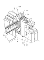
- FIG. 1 shows a component mounter 10.
- the component mounter 10 is a device for performing a component mounting operation on the circuit substrate 12.
- the component mounting machine 10 includes an apparatus main body 20, a base material conveyance holding device 22, a component mounting device 24, imaging devices 26 and 28, a component supply device 30, a bulk component supply device 32, and a control device (see FIG. 14) 34.
- the circuit substrate 12 includes a circuit board, a three-dimensional structure substrate, and the like, and the circuit board includes a printed wiring board and a printed circuit board.
- the apparatus main body 20 includes a frame portion 40 and a beam portion 42 that is overlaid on the frame portion 40.
- the substrate conveyance holding device 22 is disposed in the center of the frame portion 40 in the front-rear direction, and includes a conveyance device 50 and a clamp device 52.
- the conveyance device 50 is a device that conveys the circuit substrate 12
- the clamp device 52 is a device that holds the circuit substrate 12.
- the base material transport and holding device 22 transports the circuit base material 12 and holds the circuit base material 12 fixedly at a predetermined position.
- the conveyance direction of the circuit substrate 12 is referred to as an X direction
- a horizontal direction perpendicular to the direction is referred to as a Y direction
- a vertical direction is referred to as a Z direction. That is, the width direction of the component mounting machine 10 is the X direction, and the front-rear direction is the Y direction.
- the component mounting device 24 is disposed in the beam portion 42 and includes two work heads 60 and 62 and a work head moving device 64.
- Each of the work heads 60 and 62 has a suction nozzle (see FIG. 2) 66 and holds the component by the suction nozzle 66.
- the work head moving device 64 includes an X direction moving device 68, a Y direction moving device 70, and a Z direction moving device 72. Then, the two working heads 60 and 62 are integrally moved to arbitrary positions on the frame portion 40 by the X-direction moving device 68 and the Y-direction moving device 70. Further, as shown in FIG.
- each work head 60, 62 is detachably attached to the sliders 74, 76, and the Z-direction moving device 72 individually moves the sliders 74, 76 in the vertical direction. That is, the work heads 60 and 62 are individually moved in the vertical direction by the Z-direction moving device 72.
- the imaging device 26 is attached to the slider 74 in a state of facing downward, and is moved together with the work head 60 in the X direction, the Y direction, and the Z direction. Thereby, the imaging device 26 images an arbitrary position on the frame unit 40. As shown in FIG. 1, the imaging device 28 is disposed between the base material conveyance holding device 22 and the component supply device 30 on the frame portion 40 so as to face upward. Thereby, the imaging device 28 images the parts held by the suction nozzles 66 of the work heads 60 and 62.
- the component supply device 30 is disposed at one end of the frame portion 40 in the front-rear direction.
- the component supply device 30 includes a tray-type component supply device 78 and a feeder-type component supply device (not shown).
- the tray-type component supply device 78 is a device that supplies components placed on the tray.
- the feeder-type component supply device is a device that supplies components using a tape feeder (not shown) and a stick feeder (not shown).
- the bulk component supply device 32 is disposed at the other end portion of the frame portion 40 in the front-rear direction.
- the separated component supply device 32 is a device for aligning a plurality of components scattered in a separated state and supplying the components in an aligned state. That is, it is an apparatus that aligns a plurality of components in an arbitrary posture into a predetermined posture and supplies the components in a predetermined posture.
- the structure of the component supply apparatus 32 is demonstrated in detail.
- examples of the components supplied by the component supply device 30 and the bulk component supply device 32 include electronic circuit components, solar cell components, and power module components.
- Electronic circuit components include components having leads and components not having leads.
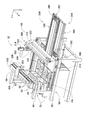
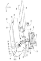
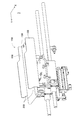
- the bulk component supply device 32 includes a main body 80, a component supply unit 82, an imaging device 84, and a component delivery device 86.
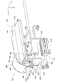
- the component supply unit 82 includes a component supplier 88, a component scattering device (see FIG. 4) 90, and a component return device (see FIG. 5) 92, and these component supplier 88 and component scattering device 90. And the component returning device 92 are integrally configured.
- the component supply unit 82 is detachably assembled to the base 96 of the main body 80. In the bulk component supply device 32, five component supply units 82 are arranged in a line in the X direction.
- the component feeder 88 has a generally rectangular parallelepiped box shape, and is disposed so as to extend in the Y direction as shown in FIGS. 4 and 5.
- the Y direction may be described as the front-rear direction of the component supplier 88
- the left direction in FIG. 5 may be described as the front
- the component supplier 88 is open at the upper surface and the front surface, and an inclined plate 104 is disposed below the opening on the upper surface of the component supplier 88.
- the inclined plate 104 is arranged in the entire width direction (X direction) of the component feeder 88 from the rear end face of the component feeder 88 toward the center, and the front end is positioned below. Inclined to do.
- a conveyor device 106 is disposed on the front side of the inclined plate 104.
- the conveyor device 106 includes a pair of rollers 108 and 110 and a conveyor belt 112.
- Each of the pair of rollers 108 and 110 is disposed inside the component supplier 88 so as to extend in the width direction of the component supplier 88 and spans the entire width of the component supplier 88. Yes.
- the roller 108 is opposed to the front end portion of the inclined plate 104, that is, the end portion located at the lowest position of the inclined plate 104 with a clearance. Note that the clearance between the front end of the inclined plate 104 and the roller 108 is smaller than that of the component supplied by the component supplier 88.
- the roller 110 is disposed obliquely above the front side of the roller 108.
- the conveyor belt 112 is wound around a pair of rollers 108 and 110.
- the conveyor belt 112 is wide, and the width of the conveyor belt 112 is slightly smaller than the inner dimension of the component feeder 88 in the width direction.
- the pair of rollers 108 and 110 are rotatable about the axis, and are rotated in a controllable manner by the operation of the rotating device 114.
- the rotation directions of the rollers 108 and 110 are counterclockwise in FIG.
- the conveyor belt 112 rotates counterclockwise in FIG. 5 between the pair of rollers 108 and 110. That is, the conveying direction by the conveyor belt 112 is obliquely upward from the front end portion of the inclined plate 104 toward the front.
- a plurality of protrusions 115 are formed on the surface of the conveyor belt 112, that is, on the conveying surface, so as to extend in the width direction of the conveyor belt 112.
- the plurality of protrusions 115 are formed at regular intervals in the rotation direction of the conveyor belt 112, and the intervals are longer than the dimensions in the length direction of the components supplied by the component supplier 88.
- a brush holding portion 116 is disposed obliquely above the front side of the roller 110 of the conveyor device 106.
- the brush holding unit 116 is disposed so as to extend in the width direction of the component supplier 88, and spans the entire width direction of the component supplier 88.
- the wide brush 118 is attached to the lower end part of the brush holding part 116 so that it may extend toward the roller 110 of the conveyor apparatus 106.
- the width direction dimension of the brush 118 is slightly smaller than the inner dimension in the width direction of the component supplier 88, and the width of the conveyor belt 112 wound around the roller 110 and the width direction of the component supplier 88 is reduced. The whole is facing with clearance.
- the clearance between the tip of the brush 118 and the conveyor belt 112 wound around the roller 110 is longer than the dimension in the thickness direction of the component supplied by the component feeder 88 and is twice the dimension in the thickness direction. It is said that it is less than.
- an inclined plate 120 is disposed obliquely below the front side of the roller 110 of the conveyor device 106.
- the inclined plate 120 is disposed in the entire width direction of the component feeder 88 from the front end surface of the component feeder 88 toward the lower side of the roller 110 so that the end on the rear side is positioned below. It is inclined to.
- an inclined plate 122 is disposed below the inclined plate 120.
- the inclined plate 122 is disposed in the entire width direction of the component feeder 88 from below the central portion of the conveyor device 106 toward the opening on the front side of the component feeder 88, and the front end portion is located below. Inclined to be located at.
- the rear end portion of the inclined plate 122 is located behind the rear end portion of the inclined plate 120, and the rear end portion of the inclined plate 122 is bent at a right angle upward. ing. Further, the front end of the inclined plate 122 is bent rearward so as to be generally horizontal.
- the base 96 is assembled with a pair of side frame portions 130 as shown in FIG.
- the pair of side frame portions 130 are erected so as to be parallel to each other and extend in the Y direction in a state of being opposed to each other.
- the distance between the pair of side frame portions 130 is slightly larger than the dimension in the width direction of the component feeder 88, and the component feeder 88 is detachable between the pair of side frame portions 130. It is attached to.
- the component scattering device 90 includes a component support member 150 and a component support member moving device 152.
- the component support member 150 includes a stage 156 and a pair of side wall portions 158.
- the stage 156 has a generally longitudinal plate shape and is disposed so as to extend forward from below the component feeder 88 mounted between the pair of side frame portions 130. Note that the upper surface of the stage 156 is generally horizontal, and is arranged with a slight clearance from the bent forward end of the inclined plate 122 of the component supplier 88 as shown in FIG. ing. Further, as shown in FIG. 4, the pair of side wall portions 158 are fixed in a state of being erected on both sides in the longitudinal direction of the stage 156, and the upper end of each side wall portion 158 is from the upper surface of the stage 156. It extends upward.
- the component support member moving device 152 includes a guide rail 160 and a slider 162 as shown in FIG.
- the guide rail 160 is disposed below the component support member 150 so as to extend in the longitudinal direction of the stage 156.
- the slider 162 is slidably attached to the guide rail 160 and slides to an arbitrary position by the operation of an electromagnetic motor (see FIG. 14) 166.
- the stage 156 of the component support member 150 is connected to the slider 162 via a connecting mechanism 168.
- the component support member 150 moves in the Y direction by the operation of the component support member moving device 152, and the stored state (see FIG. 6) stored below the component supplier 88 and from below the component supplier 88. It moves between the exposed state (see FIG. 5).
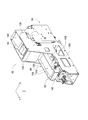
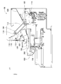
- the component return device 92 includes a component recovery container 180 and a container swing device 181 as shown in FIG. As shown in FIGS. 7 to 10, the component collection container 180 includes a pair of side wall surfaces 182, a bottom surface 184, and a partition surface 186. 9 and 10 show the component collection container 180 in a state in which one side wall surface 182 of the pair of side wall surfaces 182 is removed.
- Each of the pair of side wall surfaces 182 has a generally fan shape and an arc portion 188 having a central angle of about 90 degrees.
- the bottom surface 184 is curved along the arc portion 188 of the side wall surface 182, and the arc portions 188 of the pair of side wall surfaces 182 are fixed to both curved edges of the bottom surface 184.
- the partition surface 186 has a plate shape and is erected at the center in the bending direction of the curved bottom surface 184 while being sandwiched between the pair of side wall surfaces 182.
- the distance between the pair of side wall surfaces 182 is slightly larger than the dimension in the width direction (X direction) of the stage 156 of the component support member 150, and the end on the front side of the stage 156 is a pair. Are sandwiched between the side wall surfaces 182. Then, the parts collection container 180 is slidably supported on the pair of side wall surfaces 182 by the front end of the stage 156. Specifically, a through hole (see FIGS. 9 and 10) 190 is formed at the front end of the stage 156 so as to extend in the width direction of the stage 156. In addition, a through hole (see FIGS. 7 and 8) 192 is formed coaxially with the through hole 190 in the central portion of the side wall surface 182 opposite to the arc portion 188.
- a swing shaft (see FIGS. 7 and 8) 196 is inserted through the through hole 192 in the pair of side wall surfaces 182 and the through hole 190 in the stage 156.
- the parts collection container 180 is slidably supported by the front end of the stage 156 on the pair of side wall surfaces 182.
- the edge 198 opposite to the arc 188 of the side wall surface 182 of the component collection container 180 has an arc shape.
- the edge 198 faces the end on the front side of the side wall 158 fixed to the side surface of the stage 156, and the end on the front side of the side wall 158 is as shown in FIG.
- an arc-shaped recess 200 having substantially the same shape as the edge 198 of the side wall surface 182 is formed.
- FIG. 11 shows the component support member 150 with the component collection container 180 removed. And the edge part 198 of the side wall surface 182 and the recessed part 200 of the side wall part 158 are facing each other with a slight clearance. Thereby, the component collection container 180 swings without interfering with the side wall portion 158 of the component support member 150.
- the partition surface 186 that partitions the inside of the component collection container 180 extends toward the through hole 190 formed in the stage 156, that is, toward the swing center of the component collection container 180. Yes. Therefore, a space defined by the front surface of the partition surface 186, the bottom surface 184, and the pair of side wall surfaces 182 opens at the side of the front end portion of the stage 156, and the space is a component. It functions as the collection unit 202 of the collection container 180.
- the partition surface 186 is perpendicular to the tangent in the swing direction of the component collection container 180. For this reason, the distance between the end of the partition surface 186 that extends toward the stage 156 and the swing center of the component recovery container 180 is constant even when the component recovery container 180 swings.
- the end face on the front side of the stage 156 that is, the end face on the side where the through hole 190 is formed, is an arc surface having a shape along the swinging direction of the component collection container 180.
- the arc surface and the end of the partition surface 186 that extends toward the stage 156 face each other with a slight clearance. Therefore, when the parts collection container 180 is swinging, the slight clearance between the arc surface of the stage 156 and the end of the partition surface 186 that extends toward the stage 156 is maintained in a constant state.
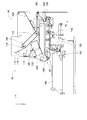
- the container swinging device 181 includes a slider 210, an air cylinder 212, and a cam mechanism 214.
- the slider 210 includes a main body 220 and a connecting part 222.
- the main body 220 of the slider 210 is slidably attached to the guide rail 160 of the component support member moving device 152.
- the connecting portion 222 is generally L-shaped, extends forward, and is fixed to the lower end of the main body 220 in a posture that extends downward.
- the air cylinder 212 is disposed so as to extend in the Y direction with the tip of the piston rod 226 facing rearward, and is fixed to the connection mechanism 168 of the component support member moving device 152 via the bracket 228. Has been.
- the tip of the piston rod 226 is fixed to a portion that extends below the connecting portion 222 of the slider 210.
- the slider 210 and the air cylinder 212 move in the Y direction together with the stage 156 as the stage 156 moves.
- the air cylinder 212 is expanded and contracted by the operation of the air cylinder 212, the slider 210 moves in a direction approaching / separating from the coupling mechanism 168.
- the slider 210 When the slider 210 is closest to the connection mechanism 168 as the air cylinder 212 is operated, the slider 210 is positioned below the stage 156 (see FIG. 9), and the slider 210 is connected to the connection mechanism 168. When the slider 210 is farthest from the front, the slider 210 is positioned slightly forward from the front end of the stage 156 (see FIG. 10).
- the cam mechanism 214 includes a holding member 230, a pressing member 232, and a pair of rollers 234.
- the holding member 230 has a shape in which both end portions of the plate-like member are bent at 90 degrees in the same direction, and the bent end portions are directed to the upper end portion of the main body portion 220 of the slider 210 in a state in which the both end portions are directed forward. It is fixed.
- a pair of cam holes 238 are formed in the holding member 230 so as to extend in the vertical direction at both bent ends.
- the pressing member 232 has a generally rectangular parallelepiped shape, and a pair of rollers 234 are coaxially disposed on a pair of opposed surfaces of the pressing member 232 so as to be rotatable.
- the pressing member 232 is held at both bent ends of the holding member 230 with the pair of rollers 234 inserted into the pair of cam holes 238.
- the push member 232 extends from between the bent ends of the holding member 230 toward the component recovery container 180, and is fixedly sandwiched by a pair of side wall surfaces 182 of the component recovery container 180. Yes. With such a structure, the component recovery container 180 swings as the slider 210 moves with the operation of the air cylinder 212.
- the slider 210 when the air cylinder 212 contracts most, the slider 210 is positioned below the front end of the stage 156, and the roller 234 of the cam mechanism 214 is a cam. The upper end of the hole 238 is engaged.
- the push member 232 is generally in a horizontal state, and the component collection container 180 to which the push member 232 is fixed is in a collection posture with the opening of the collection unit 202 facing upward.
- the partition surface 186 is inclined at about 45 degrees so as to descend from the opening of the collection unit 202 toward the bottom surface 184.
- the slider 210 moves away from the coupling mechanism 168, and the push member 232 of the cam mechanism 214 moves away from the coupling mechanism 168 as the slider 210 moves. Moving.
- the component collection container 180 is pushed by the push member 232 in the direction away from the coupling mechanism 168, and starts swinging. That is, the end of the partitioning surface 186 of the component collection container 180 on the bottom surface 184 side rises, and the opening of the collection unit 202 rotates toward the top surface of the stage 156. At this time, the end of the push member 232 that is fixed to the component collection container 180 rises and tilts as the component collection container 180 swings.
- the end of the push member 232 opposite to the end fixed to the component collection container 180 is lowered, and the inside of the cam hole 238 is lowered.
- the roller 234 moves down.
- the end of the push member 232 fixed to the parts collection container 180 is the center of the swing of the parts collection container 180, that is, the axis of the swing shaft 196 increases.
- the roller 234 descends to the lowest end in the cam hole 238.
- the push member 232 is generally in a vertical state, and the component collection container 180 to which the push member 232 is fixed is in a return posture with the opening of the collection unit 202 facing the upper surface of the stage 156. .
- the partition surface 186 is inclined at about 45 degrees so as to descend from the bottom surface 184 toward the opening of the collection unit 202.
- the imaging device 84 includes a camera 290 and a camera moving device 292.
- the camera moving device 292 includes a guide rail 296 and a slider 298.
- the guide rail 296 is fixed to the main body 80 so as to extend in the width direction (X direction) of the bulk component supply device 32 above the component supplier 88.
- the slider 298 is slidably attached to the guide rail 296, and slides to an arbitrary position by the operation of the electromagnetic motor (see FIG. 14) 299.
- the camera 290 is attached to the slider 298 so as to face downward.
- the component delivery device 86 includes a component holding head moving device 300, a component holding head 302, and two shuttle devices 304, as shown in FIG.
- the component holding head moving device 300 includes an X direction moving device 310, a Y direction moving device 312, and a Z direction moving device 314.
- the Y-direction moving device 312 has a Y slider 316 disposed above the component supply unit 82 so as to extend in the X direction.
- the Y slider 316 is driven by an electromagnetic motor (see FIG. 14) 319. , Move to any position in the Y direction.
- the X-direction moving device 310 has an X-slider 320 disposed on the side surface of the Y-slider 316.
- the X-slider 320 is moved to an arbitrary position in the X-direction by driving an electromagnetic motor (see FIG. 14) 321. Moving.
- the Z-direction moving device 314 has a Z-slider 322 disposed on the side surface of the X-slider 320, and the Z-slider 322 is moved to an arbitrary position in the Z-direction by driving an electromagnetic motor (see FIG. 14) 323. Moving.
- the component holding head 302 includes a head body 330, a suction nozzle 332, a nozzle turning device 334, and a nozzle rotating device 335, as shown in FIG.
- the head body 330 is formed integrally with the Z slider 322.
- the suction nozzle 332 holds parts and is detachably attached to the lower end portion of the holder 340.
- the holder 340 can be bent at the support shaft 344, and the operation of the nozzle turning device 334 causes the holder 340 to be bent 90 degrees upward.
- the suction nozzle 332 attached to the lower end of the holder 340 turns 90 degrees and is located at the turning position. That is, the suction nozzle 332 turns between the non-turning position and the turning position by the operation of the nozzle turning device 334.
- the nozzle rotating device 335 rotates the suction nozzle 332 around its axis.
- each of the two shuttle devices 304 includes a component carrier 388 and a component carrier moving device 390, and is fixed to the main body 80 side by side in front of the component supply unit 82.
- Five component receiving members 392 are mounted on the component carrier 388 in a row in the horizontal direction, and the components are placed on each component receiving member 392.
- the component supplied by the bulk component supply device 32 is an electronic circuit component having a lead (hereinafter sometimes abbreviated as “lead component”) 410, and the lead component 410 is The block-shaped component main body 412 and two leads 414 protruding from the bottom surface of the component main body 412 are configured.
- the component receiving member 392 is formed with a component receiving recess 416.
- the component receiving recess 416 is a stepped recess, and includes a main body receiving recess 418 that opens to the top surface of the component receiving member 392 and a lead receiving recess 420 that opens to the bottom surface of the main body receiving recess 418. Yes.
- the lead component 410 is inserted into the component receiving recess 416 with the lead 414 facing downward.
- the lead 414 is inserted into the lead receiving recess 420 and the lead component 410 is placed inside the component receiving recess 416 with the component main body 412 inserted into the main body receiving recess 418.
- the component carrier moving device 390 is a plate-like longitudinal member, and is disposed on the front side of the component supply unit 82 so as to extend in the front-rear direction.
- a component carrier 388 is slidably arranged in the front-rear direction, and slides to an arbitrary position in the front-rear direction by driving an electromagnetic motor (see FIG. 14) 430.
- the component carrier 388 slides in a direction approaching the component supply unit 82
- the component carrier 388 slides to a component receiving position located within the movement range of the component holding head 302 by the component holding head moving device 300.
- the component carrier 388 slides in the direction away from the component supply unit 82
- the component carrier 388 slides to the component supply position located within the movement range of the work heads 60 and 62 by the work head moving device 64.
- the control device 34 includes an overall control device 450, a plurality of individual control devices (only one is shown in the figure) 452, and an image processing device 454.
- the overall control device 450 is configured mainly by a computer, and is connected to the base material conveyance holding device 22, the component mounting device 24, the imaging device 26, the imaging device 28, the component supply device 30, and the loose component supply device 32. ing. Thereby, the overall control device 450 controls the base material conveyance holding device 22, the component mounting device 24, the imaging device 26, the imaging device 28, the component supply device 30, and the loose component supply device 32 in an integrated manner.
- the plurality of individual control devices 452 are configured mainly by a computer, and are provided in the base material conveyance holding device 22, the component mounting device 24, the imaging device 26, the imaging device 28, the component supply device 30, and the bulk component supply device 32. (In the figure, only the individual control device 452 corresponding to the bulk component supply device 32 is shown).
- the individual control device 452 of the bulk component supply device 32 is connected to the component scattering device 90, the component return device 92, the camera moving device 292, the component holding head moving device 300, the component holding head 302, and the shuttle device 304.
- the individual control device 452 of the bulk component supply device 32 controls the component scattering device 90, the component return device 92, the camera moving device 292, the component holding head moving device 300, the component holding head 302, and the shuttle device 304.
- the image processing device 454 is connected to the imaging device 84 and processes imaging data captured by the imaging device 84.
- the image processing device 454 is connected to the individual control device 452 of the bulk component supply device 32.
- the individual control device 452 of the bulk component supply device 32 acquires the imaging data captured by the imaging device 84.
- the component mounting operation is performed on the circuit substrate 12 held by the substrate conveyance holding device 22 with the above-described configuration. Specifically, the circuit substrate 12 is transported to the work position, and is fixedly held by the clamp device 52 at that position. Next, the imaging device 26 moves above the circuit substrate 12 and images the circuit substrate 12. Thereby, the information regarding the error of the holding position of the circuit base material 12 is obtained.
- the component supply device 30 or the bulk component supply device 32 supplies components at a predetermined supply position. It should be noted that the supply of components by the bulk component supply device 32 will be described in detail later. Then, one of the work heads 60 and 62 moves above the component supply position, and holds the component by the suction nozzle 66.
- the work heads 60 and 62 holding the components move above the imaging device 28, and the components held by the suction nozzle 66 are imaged by the imaging device 28. As a result, information on the error of the component holding position can be obtained. Then, the work heads 60 and 62 holding the components move above the circuit substrate 12 and correct the held components for errors in the holding position of the circuit substrate 12, errors in the holding position of the components, and the like. And mounted on the circuit substrate 12.
- the lead component 410 thrown from the opening on the upper surface of the component supplier 88 falls onto the inclined plate 104 of the component supplier 88 and rolls down to the lower end on the front side of the inclined plate 104. At this time, the lead component 410 that has rolled down to the lower end on the front side of the inclined plate 104 is piled up between the lower end on the front side of the inclined plate 104 and the lower end on the rear side of the conveyor device 106. Then, when the rotating device 114 of the conveyor device 106 is operated, the conveyor belt 112 of the conveyor device 106 rotates counterclockwise in FIG.
- the lead components 410 stacked between the lower end on the front side of the inclined plate 104 and the lower end on the rear side of the conveyor device 106 are conveyed by the conveyor belt 112 obliquely upward on the front side.
- the protruding portion 115 extending in the width direction (X direction) of the component feeder 88 is formed on the conveying surface of the conveyor belt 112, the lead component 410 is caught by the protruding portion 115 and is inclined by the conveyor belt 112. It is transported upward.
- the lead component 410 conveyed obliquely upward by the conveyor belt 112 passes between the upper end on the front side of the conveyor device 106 and the brush 118, and between the upper end on the front side of the conveyor device 106 and the brush 118. It falls on the inclined plate 120 disposed below.
- the lead component 410 that has fallen on the inclined plate 120 rolls backward on the inclined plate 120 and falls onto the inclined plate 122 disposed below the inclined plate 120.
- the lead component 410 that has fallen on the inclined plate 122 rolls forward and is discharged from the opening on the front side of the component feeder 88.
- the lead component 410 that has dropped from the upper end on the front side of the conveyor device 106 once falls on the inclined plate 120 and then falls on the inclined plate 122. Then, the lead component 410 is discharged from the opening on the front side of the component supplier 88. Thereby, it is possible to reduce damage due to the drop of the lead component 410.
- the component support member 150 moves from the lower side of the component feeder 88 to the front by the operation of the component support member moving device 152 in accordance with the timing at which the lead component 410 is discharged from the opening on the front side of the component feeder 88. Moved. As a result, the lead component 410 discharged from the opening on the front side of the component supplier 88 is discharged onto the upper surface of the stage 156 of the component support member 150.
- the lead component 410 discharged from the component supplier 88 onto the stage 156 rolls forward and falls from the front end of the stage 156, it is stored in the component collection container 180.
- the lead component 410 discharged from the component feeder 88 onto the stage 156 rolls sideways, the lead component 410 is dropped from the stage 156 by the side wall portion 158 of the component support member 150. Is prevented.
- the movement of the component support member 150 is stopped.
- the lead components 410 are scattered over the entire upper surface of the stage 156.
- the operation of the conveyor device 106 is stopped so that the lead component 410 is finally discharged from the component supplier 88 in synchronization with the timing at which the movement of the component support member 150 is stopped.
- the lead component 410 When the lead component 410 is scattered on the stage 156 of the component support member 150 from the component feeder 88, the lead component 410 is scattered on the stage 156 in approximately two postures as shown in FIG.
- the lead component 410 has a posture in which the two leads 414 are generally aligned in the horizontal direction (hereinafter sometimes referred to as “first posture”), and the two leads 414 are generally vertical. Scattered on the stage 156 in two postures: a posture in a state of being aligned in a direction (hereinafter may be referred to as a “second posture”).
- the camera 290 of the imaging device 84 moves above the component support member 150 by the operation of the camera moving device 292, and images the lead component 410. To do. Then, based on the image data captured by the camera 290, a lead component to be picked up (hereinafter may be abbreviated as “pickup target component”) is specified.
- the posture of the part and the position of the part are calculated for each of a plurality of parts scattered on the stage 156 based on the imaging data of the camera 290. Then, only the lead component 410 whose calculated component posture is the first posture is specified as a pickup target component. This is because, in the lead component 410 in the first posture, the side surface 500 having a large surface area faces upward, and the side surface 500 can be held by the suction nozzle 332, but in the lead component 410 in the second posture, This is because the side surface 502 having a small surface area faces upward, and the side surface 502 cannot be held by the suction nozzle 332.
- the specified pickup target component is sucked and held by the suction nozzle 332.
- the suction nozzle 332 is located at the non-turning position.
- the component holding head 302 is moved above the component carrier 388.
- the component carrier 388 moves to the component receiving position by the operation of the component carrier moving device 390.
- the suction nozzle 332 is pivoted to the pivot position. The suction nozzle 332 is rotated by the operation of the nozzle rotating device 335 so that the lead 414 of the lead component 410 held by the suction nozzle 332 in the turning position faces downward in the vertical direction.
- the lead component 410 with the lead 414 facing downward in the vertical direction is inserted into the component receiving recess 416 of the component receiving member 392.
- the lead component 410 is placed on the component receiving member 392 with the lead 414 facing downward in the vertical direction.
- the component carrier 388 When the lead component 410 is placed on the component receiving member 392, the component carrier 388 is moved to the component supply position by the operation of the component carrier moving device 390. Since the component carrier 388 moved to the component supply position is located in the movement range of the work heads 60 and 62, the lead component 410 is supplied at this position in the loose component supply device 32. As described above, in the bulk component supply device 32, the lead component 410 is supplied in a state where the lead 414 faces downward and the upper surface facing the bottom surface to which the lead 414 is connected faces upward. For this reason, the suction nozzle 66 of the work heads 60 and 62 can hold the lead component 410 appropriately.
- the lead component 410 remaining on the stage 156 is collected in the component collection container 180. Then, the lead parts 410 collected in the parts collection container 180 are scattered again on the stage 156, and the posture of the lead parts 410 is changed, so that the pickup of the lead parts 410 from the stage 156 is resumed.
- the number of lead components 410 collected in the component collection container 180 is small, even if the lead components 410 collected in the component collection container 180 are scattered on the stage 156 again, The number of parts to be picked up at is considered to be small.
- the lead components 410 collected in the component collection container 180 are not only scattered again on the stage 156, but also the lead components 410 can be replenished from the component feeder 88. desirable. That is, it is desirable to replenish the lead component 410 on the stage 156 from both the component recovery container 180 and the component supplier 88.
- the number of lead components 410 remaining on the stage 156 is equal to or less than a preset number
- lead is received from both the component collection container 180 and the component feeder 88.
- the lead parts 410 are replenished on the stage 156 and the number of lead parts 410 remaining on the stage 156 exceeds a preset number, the lead parts 410 are only fed from the parts collection container 180. Is replenished onto the stage 156.
- the component support member 150 is moved downward of the component feeder 88 by the operation of the component support member moving device 152. That is, the component support member 150 is moved from the exposed state (see FIG. 5) toward the retracted state (see FIG. 6).
- the component collection container 180 disposed at the front end of the component support member 150 is in a posture in which the opening of the collection unit 202 faces upward, that is, in a collection posture.
- the lead component 410 is discharged from the component feeder 88 onto the stage 156 of the component support member 150.
- the discharge of the lead component 410 from the component supplier 88 is the same as the above-described procedure, and thus the description thereof is omitted.
- the lead component 410 Due to the discharge of the lead component 410 from the component supplier 88, the lead component 410 remaining on the stage 156 before the discharge of the lead component 410 from the component supplier 88 on the stage 156, and the component supplier There is a lead component 410 discharged from 88. Even when the lead component 410 is discharged from the component supplier 88, the component support member 150 moves toward the retracted state. Therefore, as the component support member 150 moves, the lead component 410 on the stage 156 of the component support member 150 is dammed by the front end of the inclined plate 122 of the component feeder 88 as shown in FIG. It can be stopped. Further, as shown in FIG.
- the recovered lead component 410 is replenished onto the stage 156.
- the component support member 150 is in a retracted state as shown in FIG. Therefore, the component support member 150 is moved forward from the retracted state by the operation of the component support member moving device 152.
- the conveyor device 106 of the component feeder 88 is not operated. That is, the lead component 410 is not discharged onto the stage 156 from the component supplier 88.
- the container swinging device 181 of the component returning device 92 is operated, and the component recovery container 180 is swung.
- the movement amount of the parts support member 150 moving forward from the retracted state is set in advance, and the stage where the lead parts 410 are to be supplied from the parts collection container 180.
- a predetermined area 156 is the amount of movement of the component support member 150 when exposed from below the component supplier 88. Further, the movement of the component support member 150 does not stop even when the component collection container 180 swings. That is, the component collection container 180 swings while the component support member 150 moves.
- the air cylinder 212 of the container peristaltic device 181 is expanded from the contracted state.
- the air cylinder 212 is stretched at a relatively high speed and at a stretch, so that the component collection container 180 swings vigorously. That is, the posture of the parts collection container 180 changes rapidly from a posture with the opening of the collection unit 202 facing upward (collection posture) to a posture with the opening of the collection unit 202 facing the stage 156 (return posture).
- the lead component 410 recovered in the component recovery container 180 is released toward the stage 156 vigorously.
- the bottom surface 184 of the component recovery container 180 has an arc shape as described above, the lead component 410 recovered in the component recovery container 180 is accelerated along the arc-shaped bottom surface 184 and the stage 156. It is released vigorously toward.
- the lead component 410 collected in the component collection container 180 is discharged to a location relatively distant from the component collection container 180, and the lead components 410 are scattered over a relatively wide range of the stage 156. That is, the lead components 410 collected in the component collection container 180 are replenished on the stage 156 in a scattered state.
- the component support member 150 moves even when the component collection container 180 is swinging, and when the component support member 150 reaches an exposed state, the movement of the component support member 150 stops.
- the air cylinder 212 is contracted, and the posture of the component collection container 180 is such that the opening of the collection unit 202 faces the stage 156 (return). (Posture) is returned to a posture (collection posture) with the opening of the recovery unit 202 facing upward.
- the lead component 410 is replenished on the stage 156 only from the component recovery container 180, first, as in the case where the lead component 410 is replenished from both the component recovery container 180 and the component feeder 88, first, The component support member 150 is moved from the exposed state toward the retracted state. However, replenishment of the lead component 410 from the component supplier 88 is not performed. As the component support member 150 moves, the lead component 410 on the stage 156 is blocked by the front end of the inclined plate 122 of the component feeder 88. Further, the component support member 150 is moved until it reaches the retracted state, whereby the lead component 410 on the stage 156 is scraped into the component collection container 180.
- the lead component 410 remaining on the stage 156 is recovered in the component recovery container 180.
- the component support member 150 reaches the retracted state, the component support member 150 is moved again toward the exposed state.
- the parts collection container 180 is swung according to the above-described procedure.
- the lead component 410 recovered in the component recovery container 180 is supplied on the stage 156.
- the lead component 410 is supplied onto the stage 156.
- the lead component 410 replenished on the stage 156 is changed.
- the pickup target component is identified again based on the image data captured by the camera 290 of the imaging device 84 and captured by the camera 290.
- the specified pickup target component is sucked and held by the suction nozzle 332, and the lead component 410 is supplied by the loose component supply device 32 according to the above-described procedure.
- the lead component 410 that cannot be picked up is recovered. It is collected in the container 180.
- the lead component 410 that cannot be picked up and the lead component 410 discharged from the component supplier 88 onto the stage 156 are collected in the component collection container 180.
- the lead components 410 collected in the component collection container 180 are again scattered on the stage 156, and the posture of the lead components 410 on the stage 156 is changed. As a result, it is possible to replenish the lead component 410 in a posture capable of being picked up on the stage 156 in a relatively short time.
- the parts support member 150 does not stop. That is, the lead component 410 recovered in the component recovery container 180 is supplied onto the stage 156 while the component support member 150 moves. As a result, the component support member 150 can be quickly returned to the state in which the lead component 410 can be picked up from above the stage 156, that is, the exposed state, and the tact time can be shortened.
- the bulk component supply device 32 is an example of a component supply device.
- the inclined plate 122 is an example of a damming member and a recovery device.
- the component support member 150 is an example of a component support portion.
- the component support member moving device 152 is an example of a moving device and a collection device.
- the upper surface of the stage 156 is an example of a support surface.
- the parts collection container 180 is an example of a collection container.
- the container peristaltic device 181 is an example of a container posture changing device.
- this invention is not limited to the said Example, It is possible to implement in the various aspect which gave various change and improvement based on the knowledge of those skilled in the art. Specifically, for example, in the above embodiment, the bottom surface 184 of the component collection container 180 is bent in an arc shape, but may be bent in multiple stages.
- the parts collection container 180 is swung and the lead parts 410 collected in the parts collection container 180 are scattered on the stage 156.
- the posture of the component collection container 180 may be changed, and the lead components 410 collected in the component collection container 180 may be scattered on the stage 156.
- the component support member 150 is moved downward of the component feeder 88, and the lead component 410 remaining on the stage 156 is collected in the component collection container 180.
- the abutting member is disposed at a height capable of abutting on the lead components 410 scattered on the lead, and the abutting member is moved toward the component collection container 180, and the leads scraped by the abutting member are collected.
- the part 410 may be collected in the part collection container 180.
- the component support member 150 when the worker puts the lead component 410 into the component supplier 88, the component support member 150 is moved to the retracted state, but the component support member 150 is moved to any position. Even in this state, the operator can put the lead component 410 into the component supplier 88.
- the component support member 150 when the lead component 410 is replenished on the stage 156 from both the component recovery container 180 and the component supplier 88, the component support member 150 is moved from the exposed state to the retracted state. At this time, the lead component 410 is discharged from the component supplier 88, but the lead component 410 may be discharged from the component supplier 88 when the component support member 150 is moved from the retracted state to the exposed state. . That is, in the above embodiment, the lead component 410 discharged from the component supplier 88 onto the stage 156 is once recovered into the component recovery container 180 and then supplied from the component recovery container 180 onto the stage 156. Yes.
- the lead component 410 is discharged from the component supplier 88 by discharging the lead component 410 from the component supplier 88. Without being collected in 180, it is kept scattered on stage 156. That is, when the component support member 150 moves from the retracted state to the exposed state, the lead component 410 is replenished from the component feeder 88 onto the stage 156, and the component recovery container 180 is swung from the component recovery container 180. The lead component 410 is supplied on the stage 156.
- the present invention is applied to a component having a lead.
- the present invention can be applied to various types of components. Specifically, the present invention can be applied to, for example, solar cell components, power module components, electronic circuit components without leads, and the like.
Abstract
ばら部品供給装置は、複数の部品を散在させた状態で支持する部品支持部材150と、部品支持部材に支持された部品を自身の開口から回収するための部品回収容器180と、部品支持部材を搖動させ、部品回収容器の開口を部品支持部材に向けることで、部品回収容器に回収された部品を部品支持部材に散在させる容器搖動装置とを備える。これにより、部品回収容器から、直接、部品支持部材に部品が散在されるため、サイクルタイムの短縮を図ることが可能となり、部品供給装置の実用性が向上する。
Description
本発明は、複数の部品を散在された状態で支持する部品支持部から部品を供給する部品供給装置に関するものである。
部品供給装置には、ホッパー等の部品収容器から部品支持部の上に部品が散在され、その散在された状態で部品を供給する装置が存在する。このような部品供給装置では、部品支持部の上に散在された部品が、吸着ノズル等により保持されるが、保持不能な姿勢で部品支持部の上に散在される場合もある。このような部品は、部品支持部の隣に配設された回収容器に、一旦、回収される。そして、その回収容器から部品収容器に戻され、再度、部品収容器から部品支持部の上に部品が散在される。下記特許文献には、このような部品供給装置の一例が記載されている。
上記特許文献に記載の技術によれば、回収容器に回収された部品が部品収容器に戻され、その部品収容器から、再度、部品支持部の上に部品が散在されることで、部品支持部の上での部品の姿勢が変更され、部品支持部の上から部品を保持することが可能となる。しかしながら、部品支持部の上から回収容器に部品を回収し、その回収された部品を部品収容器に戻し、そして、その部品収容器から、再度、部品支持部の上に部品を散在していては、サイクルタイムが長くなる。また、回収容器から部品収容器に部品が戻される際に、部品が部品収容器の外部に落下し、部品供給装置が異常停止する虞もある。このように、部品支持部に支持された部品を供給する部品供給装置には、改良の余地が多分に残されており、種々の改良を施すことで、部品供給装置の実用性は向上すると考えられる。本発明は、そのような実情に鑑みてなされたものであり、実用性の高い部品供給装置の提供を課題とする。
上記課題を解決するために、本発明に記載の部品供給装置は、複数の部品を散在させた状態で支持面において支持する部品支持部と、前記部品支持部の隣に配設され、前記支持面において支持された部品を自身の開口から回収するための回収容器と、前記支持面において支持された部品を前記回収容器の開口から前記回収容器の内部に回収する回収装置と、前記回収容器の開口を前記支持面に向けるように、前記回収容器の姿勢を変化させることで、前記回収容器の内部に回収された部品を前記支持面に散在させる容器姿勢変化装置とを備える。
本発明に記載の部品供給装置では、回収容器の開口を部品支持部の支持面に向けるように、回収容器の姿勢を変化させることで、回収容器の内部に回収された部品が部品支持部の支持面に散在される。これにより、回収容器に回収された部品を部品収容器に戻す必要が無くなり、回収容器から部品収容器に戻す際の部品の落下を無くすことが可能となる。また、回収容器から、直接、部品支持部に部品が散在されるため、サイクルタイムの短縮を図ることが可能となる。このため、本発明の部品供給装置によれば、部品供給装置の実用性が向上する。
以下、本発明を実施するための形態として、本発明の実施例を、図を参照しつつ詳しく説明する。
<部品実装機の構成>
図1に、部品実装機10を示す。部品実装機10は、回路基材12に対する部品の実装作業を実行するための装置である。部品実装機10は、装置本体20、基材搬送保持装置22、部品装着装置24、撮像装置26,28、部品供給装置30、ばら部品供給装置32、制御装置(図14参照)34を備えている。なお、回路基材12として、回路基板、三次元構造の基材等が挙げられ、回路基板として、プリント配線板、プリント回路板等が挙げられる。
図1に、部品実装機10を示す。部品実装機10は、回路基材12に対する部品の実装作業を実行するための装置である。部品実装機10は、装置本体20、基材搬送保持装置22、部品装着装置24、撮像装置26,28、部品供給装置30、ばら部品供給装置32、制御装置(図14参照)34を備えている。なお、回路基材12として、回路基板、三次元構造の基材等が挙げられ、回路基板として、プリント配線板、プリント回路板等が挙げられる。
装置本体20は、フレーム部40と、そのフレーム部40に上架されたビーム部42とによって構成されている。基材搬送保持装置22は、フレーム部40の前後方向の中央に配設されており、搬送装置50とクランプ装置52とを有している。搬送装置50は、回路基材12を搬送する装置であり、クランプ装置52は、回路基材12を保持する装置である。これにより、基材搬送保持装置22は、回路基材12を搬送するとともに、所定の位置において、回路基材12を固定的に保持する。なお、以下の説明において、回路基材12の搬送方向をX方向と称し、その方向に直角な水平の方向をY方向と称し、鉛直方向をZ方向と称する。つまり、部品実装機10の幅方向は、X方向であり、前後方向は、Y方向である。
部品装着装置24は、ビーム部42に配設されており、2台の作業ヘッド60,62と作業ヘッド移動装置64とを有している。各作業ヘッド60,62は、吸着ノズル(図2参照)66を有しており、吸着ノズル66によって部品を保持する。また、作業ヘッド移動装置64は、X方向移動装置68とY方向移動装置70とZ方向移動装置72とを有している。そして、X方向移動装置68とY方向移動装置70とによって、2台の作業ヘッド60,62は、一体的にフレーム部40上の任意の位置に移動させられる。また、各作業ヘッド60,62は、図2に示すように、スライダ74,76に着脱可能に装着されており、Z方向移動装置72は、スライダ74,76を個別に上下方向に移動させる。つまり、作業ヘッド60,62は、Z方向移動装置72によって、個別に上下方向に移動させられる。
撮像装置26は、下方を向いた状態でスライダ74に取り付けられており、作業ヘッド60とともに、X方向,Y方向およびZ方向に移動させられる。これにより、撮像装置26は、フレーム部40上の任意の位置を撮像する。撮像装置28は、図1に示すように、フレーム部40上の基材搬送保持装置22と部品供給装置30との間に、上を向いた状態で配設されている。これにより、撮像装置28は、作業ヘッド60,62の吸着ノズル66に保持された部品を撮像する。
部品供給装置30は、フレーム部40の前後方向での一方側の端部に配設されている。部品供給装置30は、トレイ型部品供給装置78とフィーダ型部品供給装置(図示省略)とを有している。トレイ型部品供給装置78は、トレイ上に載置された状態の部品を供給する装置である。フィーダ型部品供給装置は、テープフィーダ(図示省略)、スティックフィーダ(図示省略)によって部品を供給する装置である。
ばら部品供給装置32は、フレーム部40の前後方向での他方側の端部に配設されている。ばら部品供給装置32は、ばらばらに散在された状態の複数の部品を整列させて、整列させた状態で部品を供給する装置である。つまり、任意の姿勢の複数の部品を、所定の姿勢に整列させて、所定の姿勢の部品を供給する装置である。以下に、部品供給装置32の構成について詳しく説明する。なお、部品供給装置30および、ばら部品供給装置32によって供給される部品として、電子回路部品,太陽電池の構成部品,パワーモジュールの構成部品等が挙げられる。また、電子回路部品には、リードを有する部品,リードを有さない部品等が有る。
ばら部品供給装置32は、図3に示すように、本体80と、部品供給ユニット82と、撮像装置84と、部品引渡し装置86とを有している。
(a)部品供給ユニット
部品供給ユニット82は、部品供給器88と部品散在装置(図4参照)90と部品戻し装置(図5参照)92とを含み、それら部品供給器88と部品散在装置90と部品戻し装置92とが一体的に構成されたものである。部品供給ユニット82は、本体80のベース96に着脱可能に組み付けられており、ばら部品供給装置32では、5台の部品供給ユニット82が、X方向に1列に並んで配設されている。
部品供給ユニット82は、部品供給器88と部品散在装置(図4参照)90と部品戻し装置(図5参照)92とを含み、それら部品供給器88と部品散在装置90と部品戻し装置92とが一体的に構成されたものである。部品供給ユニット82は、本体80のベース96に着脱可能に組み付けられており、ばら部品供給装置32では、5台の部品供給ユニット82が、X方向に1列に並んで配設されている。
(i)部品供給器
部品供給器88は、概して直方体の箱形状をなし、図4及び図5に示すように、Y方向に延びるように配設されている。なお、Y方向を部品供給器88の前後方向と記載し、図5での左方向を前方と、図5での右方向を後方と記載する場合がある。つまり、部品供給ユニット82において、部品戻し装置92が配設されている側に向かう方向を、前方と記載し、部品供給器88が配設されている側に向かう方向を、後方と記載する場合がある。
部品供給器88は、概して直方体の箱形状をなし、図4及び図5に示すように、Y方向に延びるように配設されている。なお、Y方向を部品供給器88の前後方向と記載し、図5での左方向を前方と、図5での右方向を後方と記載する場合がある。つまり、部品供給ユニット82において、部品戻し装置92が配設されている側に向かう方向を、前方と記載し、部品供給器88が配設されている側に向かう方向を、後方と記載する場合がある。
部品供給器88は、上面と前面とにおいて開口しており、部品供給器88の上面の開口の下方には、傾斜板104が配設されている。傾斜板104は、部品供給器88の後方側の端面から中央方向に向かって、部品供給器88の幅方向(X方向)の全体に配設されており、前方側の端部が下方に位置するように傾斜している。
また、傾斜板104の前方側には、図5に示すように、コンベア装置106が配設されている。コンベア装置106は、1対のローラ108,110とコンベアベルト112とを有している。1対のローラ108,110の各々は、部品供給器88の内部において、部品供給器88の幅方向に延びるように配設されており、部品供給器88の幅方向の全体に架け渡されている。また、ローラ108は、傾斜板104の前方側の端部、つまり、傾斜板104の最も下方に位置する端部とクリアランスのある状態で対向している。なお、傾斜板104の前方側の端部とローラ108とのクリアランスは、部品供給器88によって供給される部品より小さくされている。また、ローラ110は、ローラ108の前方側の斜め上方に配設されている。そして、コンベアベルト112が、1対のローラ108,110に巻き掛けられている。なお、コンベアベルト112は、幅広とされており、コンベアベルト112の幅方向の寸法は、部品供給器88の幅方向の内寸より僅かに小さくされている。
また、1対のローラ108,110は軸心周りに回転可能とされており、回転装置114の作動により制御可能に回転する。なお、各ローラ108,110の回転方向は、図5での反時計回りの方向とされている。これにより、コンベアベルト112が、1対のローラ108,110の間において、図5での反時計回りに回転する。つまり、コンベアベルト112による搬送方向は、傾斜板104の前端部から前方に向かって斜め上方とされている。なお、コンベアベルト112の表面、つまり、搬送面には、コンベアベルト112の幅方向に延びるように、複数の突起部115が形成されている。複数の突起部115は、コンベアベルト112の回転方向において一定の間隔で形成されており、その間隔は、部品供給器88によって供給される部品の長さ方向の寸法より長くされている。
また、コンベア装置106のローラ110の前方側の斜め上方には、ブラシ保持部116が配設されている。ブラシ保持部116は、部品供給器88の幅方向に延びるように配設されており、部品供給器88の幅方向の全体に架け渡されている。そして、そのブラシ保持部116の下端部には、コンベア装置106のローラ110に向かって延び出すように、幅広のブラシ118が取り付けられている。なお、ブラシ118の幅方向の寸法は、部品供給器88の幅方向の内寸より僅かに小さくされており、ローラ110に巻き掛けられているコンベアベルト112と、部品供給器88の幅方向の全体に渡って、クリアランスのある状態で対向している。なお、ブラシ118の先端と、ローラ110に巻き掛けられているコンベアベルト112とのクリアランスは、部品供給器88によって供給される部品の厚さ方向の寸法より長く、厚さ方向の寸法の2倍未満とされている。
また、コンベア装置106のローラ110の前方側の斜め下方には、傾斜板120が配設されている。傾斜板120は、部品供給器88の前方側の端面からローラ110の下方に向かって、部品供給器88の幅方向の全体に配設されており、後方側の端部が下方に位置するように傾斜している。さらに、その傾斜板120の下方にも、傾斜板122が配設されている。傾斜板122は、コンベア装置106の中央部の下方から部品供給器88の前方側の開口に向かって、部品供給器88の幅方向の全体に配設されており、前方側の端部が下方に位置するように傾斜している。なお、傾斜板122の後方側の端部は、傾斜板120の後方側の端部より後方に位置しており、その傾斜板122の後方側の端部は、上方に向かって直角に屈曲されている。また、傾斜板122の前方側の端部は、概して水平となるように後方に向かって屈曲されている。
なお、ベース96には、図4に示すように、1対のサイドフレーム部130が組み付けられている。1対のサイドフレーム部130は、対向した状態で互いに平行且つ、Y方向に延びるように立設されている。そして、1対のサイドフレーム部130の間の距離は、部品供給器88の幅方向の寸法より僅かに大きくされており、1対のサイドフレーム部130の間に、部品供給器88が着脱可能に装着されている。
(ii)部品散在装置
部品散在装置90は、部品支持部材150と部品支持部材移動装置152とを含む。部品支持部材150は、ステージ156と1対の側壁部158とによって構成されている。ステージ156は、概して長手形状の板形状をなし、1対のサイドフレーム部130の間に装着された部品供給器88の下方から前方に延び出すように、配設されている。なお、ステージ156の上面は、概して水平とされており、図5に示すように、部品供給器88の傾斜板122の屈曲された前方側の端部と僅かなクリアランスのある状態で配設されている。また、1対の側壁部158は、図4に示すように、ステージ156の長手方向の両側部に立設された状態で固定されており、各側壁部158の上端は、ステージ156の上面より上方に延び出している。
部品散在装置90は、部品支持部材150と部品支持部材移動装置152とを含む。部品支持部材150は、ステージ156と1対の側壁部158とによって構成されている。ステージ156は、概して長手形状の板形状をなし、1対のサイドフレーム部130の間に装着された部品供給器88の下方から前方に延び出すように、配設されている。なお、ステージ156の上面は、概して水平とされており、図5に示すように、部品供給器88の傾斜板122の屈曲された前方側の端部と僅かなクリアランスのある状態で配設されている。また、1対の側壁部158は、図4に示すように、ステージ156の長手方向の両側部に立設された状態で固定されており、各側壁部158の上端は、ステージ156の上面より上方に延び出している。
また、部品支持部材移動装置152は、図5に示すように、ガイドレール160とスライダ162とを含む。ガイドレール160は、部品支持部材150の下方において、ステージ156の長手方向に延びるように配設されている。スライダ162は、ガイドレール160にスライド可能に取り付けられており、電磁モータ(図14参照)166の作動により、任意の位置にスライドする。また、部品支持部材150のステージ156は、連結機構168を介してスライダ162に連結されている。これにより、部品支持部材150は、部品支持部材移動装置152の作動によりY方向に移動し、部品供給器88の下方に格納された格納状態(図6参照)と、部品供給器88の下方から露出した露出状態(図5参照)との間で移動する。
(iii)部品戻し装置
部品戻し装置92は、図5に示すように、部品回収容器180と容器搖動装置181とを含む。部品回収容器180は、図7乃至図10に示すように、1対の側壁面182と底面184と仕切面186とによって構成されている。なお、図9及び図10では、1対の側壁面182のうちの一方の側壁面182が取り外された状態の部品回収容器180が示されている。
部品戻し装置92は、図5に示すように、部品回収容器180と容器搖動装置181とを含む。部品回収容器180は、図7乃至図10に示すように、1対の側壁面182と底面184と仕切面186とによって構成されている。なお、図9及び図10では、1対の側壁面182のうちの一方の側壁面182が取り外された状態の部品回収容器180が示されている。
1対の側壁面182の各々は、概して扇形状をなし、中心角を約90度とする円弧部188を有している。底面184は、側壁面182の円弧部188に沿って湾曲されており、底面184の湾曲された両縁部に、1対の側壁面182の円弧部188が固定されている。また、仕切面186は板状をなし、1対の側壁面182によって挟まれた状態で、湾曲された底面184の湾曲方向における中央部に立設されている。これにより、部品回収容器180の内部が、1対の側壁面182と底面184とによって区画され、その部品回収容器180の内部が、仕切面186によって仕切られている。
また、1対の側壁面182の間の距離は、部品支持部材150のステージ156の幅方向(X方向)の寸法より僅かに大きくされており、ステージ156の前方側の端部が、1対の側壁面182によって挟まれている。そして、部品回収容器180が、1対の側壁面182において、ステージ156の前方側の端部によって搖動可能に支持されている。詳しくは、ステージ156の前方側の端部には、ステージ156の幅方向に延びるように、貫通穴(図9及び図10参照)190が形成されている。また、側壁面182の円弧部188と反対側の中央部には、貫通穴190と同軸的に貫通穴(図7及び図8参照)192が形成されている。そして、1対の側壁面182の貫通穴192と、ステージ156の貫通穴190とに、揺動軸(図7及び図8参照)196が挿通されている。これにより、部品回収容器180が、1対の側壁面182において、ステージ156の前方側の端部によって搖動可能に支持される。
また、図7及び図8に示すように、部品回収容器180の側壁面182の円弧部188と反対側の縁部198は円弧形状とされている。そして、その縁部198は、ステージ156の側面に固定される側壁部158の前方側の端部と対向しており、その側壁部158の前方側の端部には、図11に示すように、側壁面182の縁部198と略同形状の円弧形状の凹部200が形成されている。なお、図11は、部品回収容器180が取り外された状態の部品支持部材150が示されている。そして、側壁面182の縁部198と側壁部158の凹部200とは、僅かなクリアランスのある状態で対向している。これにより、部品回収容器180は、部品支持部材150の側壁部158と干渉することなく搖動する。
なお、部品回収容器180の内部を仕切る仕切面186は、図9及び図10に示すように、ステージ156に形成された貫通穴190、つまり、部品回収容器180の搖動中心に向かって延び出している。このため、仕切面186の前方側の面と、底面184と、1対の側壁面182とによって区画される空間が、ステージ156の前方側の端部の側方で開口し、その空間が部品回収容器180の回収部202として機能する。
また、仕切面186は、部品回収容器180の搖動方向における接線に対して直角とされている。このため、仕切面186のステージ156に向かって延び出す側の端部と、部品回収容器180の搖動中心との間の距離は、部品回収容器180が搖動しても一定である。また、ステージ156の前方側の端面、つまり、貫通穴190が形成されている側の端面は、部品回収容器180の搖動方向に沿った形状の円弧面とされている。そして、その円弧面と、仕切面186のステージ156に向かって延び出す側の端部とは、僅かなクリアランスのある状態で対向している。このため、部品回収容器180が搖動している際に、ステージ156の円弧面と、仕切面186のステージ156に向かって延び出す側の端部との僅かなクリアランスは、一定の状態で維持される。
また、容器搖動装置181は、スライダ210とエアシリンダ212とカム機構214とを含む。スライダ210は、本体部220と連結部222とによって構成されている。スライダ210の本体部220は、部品支持部材移動装置152のガイドレール160にスライド可能に取り付けられている。そして、連結部222は、概してL字型をなし、前方に延び出すとともに、下方に延び出す姿勢で、本体部220の下端部に固定されている。
また、エアシリンダ212は、ピストンロッド226の先端部を後方に向けた状態でY方向に延びるように配設されており、ブラケット228を介して、部品支持部材移動装置152の連結機構168に固定されている。そして、ピストンロッド226の先端部がスライダ210の連結部222の下方に延び出す部分に固定されている。これにより、スライダ210及びエアシリンダ212は、ステージ156の移動に伴って、ステージ156と共にY方向に移動する。また、エアシリンダ212の作動によってエアシリンダ212が伸縮することで、スライダ210が、連結機構168に対して接近・離間する方向に移動する。なお、エアシリンダ212の作動に伴って、スライダ210が連結機構168に最も接近している際に、スライダ210はステージ156の下方に位置しており(図9参照)、スライダ210が連結機構168から最も離間している際に、スライダ210はステージ156の前方側の端部より僅かに前方側に位置している(図10参照)。
また、カム機構214は、図9及び図10に示すように、保持部材230と押部材232と1対のローラ234とを含む。保持部材230は、板状の部材の両端部を同じ方向に90度に屈曲させた形状をなし、その屈曲された両端部を前方に向けた状態で、スライダ210の本体部220の上端部に固定されている。そして、その保持部材230には、屈曲された両端部に上下方向に延びるように、1対のカム穴238が形成されている。
また、押部材232は、概して直方体形状をなし、押部材232の対向する1対の面に、1対のローラ234が同軸的に回転可能に配設されている。そして、それら1対のローラ234が1対のカム穴238に挿入された状態で、押部材232が、保持部材230の屈曲された両端部において保持されている。また、押部材232は、保持部材230の屈曲された両端部の間から部品回収容器180に向かって延び出しており、その部品回収容器180の1対の側壁面182によって固定的に挟持されている。このような構造により、エアシリンダ212の作動に伴ってスライダ210が移動することで、部品回収容器180が搖動する。
詳しくは、図7及び図9に示すように、エアシリンダ212が最も収縮した際に、スライダ210はステージ156の前方側の端部の下方に位置しており、カム機構214のローラ234はカム穴238の上端部において係合している。この際、押部材232は、概して水平な状態とされており、その押部材232が固定されている部品回収容器180は、回収部202の開口を上方に向けた回収姿勢とされる。なお、回収姿勢の部品回収容器180では、仕切面186が、回収部202の開口から底面184に向かって下降するように、約45度に傾斜している。
そして、エアシリンダ212が最も収縮した状態から伸長すると、スライダ210は連結機構168から離れる方向に移動し、スライダ210の移動に伴って、カム機構214の押部材232も連結機構168から離れる方向に移動する。これにより、部品回収容器180が、押部材232によって連結機構168から離れる方向に向かって押され、揺動を開始する。つまり、部品回収容器180の仕切面186の底面184側の端部が上昇し、回収部202の開口がステージ156の上面に向かって回動する。この際、押部材232は、部品回収容器180の搖動に伴って、部品回収容器180に固定されている側の端部が上昇し、傾斜する。このため、押部材232の部品回収容器180に固定されている側の端部と反対側の端部、つまり、ローラ234が配設されている側の端部が下降し、カム穴238の内部においてローラ234が下降する。なお、部品回収容器180の搖動に伴って、押部材232の部品回収容器180に固定されている側の端部が、部品回収容器180の搖動中心、つまり、揺動軸196の軸心の高さまで上昇すると、ローラ234がカム穴238の内部において最下端まで下降する。
続いて、エアシリンダ212が更に伸長すると、スライダ210及びカム機構214の押部材232が連結機構168から更に離れる方向に移動し、部品回収容器180が更に搖動する。この際、押部材232の部品回収容器180に固定されている側の端部が、部品回収容器180の搖動中心、つまり、揺動軸196の軸心の高さより上方に上昇し、ローラ234がカム穴238の内部において上昇する。そして、エアシリンダ212が最も伸長すると、図8及び図10に示すように、スライダ210はステージ156の前方側の端部より前方側に移動し、ローラ234はカム穴238の上端部まで上昇する。この際、押部材232は、概して鉛直な状態とされており、その押部材232が固定されている部品回収容器180は、回収部202の開口をステージ156の上面に向けた戻し姿勢とされる。なお、戻し姿勢の部品回収容器180では、仕切面186が、底面184から回収部202の開口に向かって下降するように、約45度に傾斜している。
(b)撮像装置
撮像装置84は、図3に示すように、カメラ290とカメラ移動装置292とを含む。カメラ移動装置292は、ガイドレール296とスライダ298とを含む。ガイドレール296は、部品供給器88の上方において、ばら部品供給装置32の幅方向(X方向)に延びるように、本体80に固定されている。スライダ298は、ガイドレール296にスライド可能に取り付けられており、電磁モータ(図14参照)299の作動により、任意の位置にスライドする。また、カメラ290は、下方を向いた状態でスライダ298に装着されている。
撮像装置84は、図3に示すように、カメラ290とカメラ移動装置292とを含む。カメラ移動装置292は、ガイドレール296とスライダ298とを含む。ガイドレール296は、部品供給器88の上方において、ばら部品供給装置32の幅方向(X方向)に延びるように、本体80に固定されている。スライダ298は、ガイドレール296にスライド可能に取り付けられており、電磁モータ(図14参照)299の作動により、任意の位置にスライドする。また、カメラ290は、下方を向いた状態でスライダ298に装着されている。
(c)部品引渡し装置
部品引渡し装置86は、図3に示すように、部品保持ヘッド移動装置300と部品保持ヘッド302と2台のシャトル装置304とを含む。
部品引渡し装置86は、図3に示すように、部品保持ヘッド移動装置300と部品保持ヘッド302と2台のシャトル装置304とを含む。
部品保持ヘッド移動装置300は、X方向移動装置310とY方向移動装置312とZ方向移動装置314とを含む。Y方向移動装置312は、X方向に延びるように、部品供給ユニット82の上方に配設されたYスライダ316を有しており、Yスライダ316は、電磁モータ(図14参照)319の駆動により、Y方向の任意の位置に移動する。X方向移動装置310は、Yスライダ316の側面に配設されたXスライダ320を有しており、Xスライダ320は、電磁モータ(図14参照)321の駆動により、X方向の任意の位置に移動する。Z方向移動装置314は、Xスライダ320の側面に配設されたZスライダ322を有しており、Zスライダ322は、電磁モータ(図14参照)323の駆動により、Z方向の任意の位置に移動する。
部品保持ヘッド302は、図12に示すように、ヘッド本体330と吸着ノズル332とノズル旋回装置334とノズル回転装置335とを含む。ヘッド本体330は、Zスライダ322と一体的に形成されている。吸着ノズル332は、部品を保持するものであり、ホルダ340の下端部に着脱可能に装着されている。ホルダ340は、支持軸344において屈曲可能とされており、ノズル旋回装置334の作動により、ホルダ340が上方向に90度屈曲する。これにより、ホルダ340の下端部に装着されている吸着ノズル332は、90度旋回し、旋回位置に位置する。つまり、吸着ノズル332は、ノズル旋回装置334の作動により、非旋回位置と旋回位置との間で旋回する。また、ノズル回転装置335は、吸着ノズル332をそれの軸心周りに回転させる。
また、2台のシャトル装置304の各々は、図3に示すように、部品キャリヤ388と部品キャリヤ移動装置390とを含み、部品供給ユニット82の前方側に横方向に並んで、本体80に固定されている。部品キャリヤ388には、5個の部品受け部材392が、横方向に一列に並んだ状態で装着されており、各部品受け部材392に、部品が載置される。
詳しくは、ばら部品供給装置32で供給される部品は、図13に示すように、リードを有する電子回路部品(以下、「リード部品」と略す場合がある)410であり、リード部品410は、ブロック状の部品本体412と、部品本体412の底面から突出する2本のリード414とから構成されている。また、部品受け部材392には、部品受容凹部416が形成されている。部品受容凹部416は、段付き形状の凹部であり、部品受け部材392の上面に開口する本体部受容凹部418と、その本体部受容凹部418の底面に開口するリード受容凹部420とから構成されている。そして、リード部品410は、リード414が下方を向く姿勢で、部品受容凹部416の内部に挿入される。これにより、リード414がリード受容凹部420に挿入されるとともに、部品本体412が本体部受容凹部418に挿入された状態で、リード部品410が部品受容凹部416の内部に載置される。
また、部品キャリヤ移動装置390は、図3に示すように、板状の長手部材であり、前後方向に延びるように、部品供給ユニット82の前方側に配設されている。部品キャリヤ移動装置390の上面には、部品キャリヤ388が前後方向にスライド可能に配設されており、電磁モータ(図14参照)430の駆動により、前後方向の任意の位置にスライドする。なお、部品キャリヤ388が、部品供給ユニット82に接近する方向にスライドした際には、部品保持ヘッド移動装置300による部品保持ヘッド302の移動範囲内に位置する部品受取位置までスライドする。一方、部品キャリヤ388が、部品供給ユニット82から離れる方向にスライドした際には、作業ヘッド移動装置64による作業ヘッド60,62の移動範囲内に位置する部品供給位置までスライドする。
また、制御装置34は、図14に示すように、統括制御装置450と、複数の個別制御装置(図では1つのみ図示されている)452と、画像処理装置454とを含む。統括制御装置450は、コンピュータを主体として構成されたものであり、基材搬送保持装置22,部品装着装置24,撮像装置26,撮像装置28,部品供給装置30,ばら部品供給装置32に接続されている。これにより、統括制御装置450は、基材搬送保持装置22,部品装着装置24,撮像装置26,撮像装置28,部品供給装置30,ばら部品供給装置32を統括して制御する。複数の個別制御装置452は、コンピュータを主体として構成されたものであり、基材搬送保持装置22,部品装着装置24,撮像装置26,撮像装置28,部品供給装置30,ばら部品供給装置32に対応して設けられている(図では、ばら部品供給装置32に対応する個別制御装置452のみが図示されている)。ばら部品供給装置32の個別制御装置452は、部品散在装置90,部品戻し装置92,カメラ移動装置292,部品保持ヘッド移動装置300,部品保持ヘッド302,シャトル装置304に接続されている。これにより、ばら部品供給装置32の個別制御装置452は、部品散在装置90,部品戻し装置92,カメラ移動装置292,部品保持ヘッド移動装置300,部品保持ヘッド302,シャトル装置304を制御する。また、画像処理装置454は、撮像装置84に接続されており、撮像装置84により撮像された撮像データを処理する。その画像処理装置454は、ばら部品供給装置32の個別制御装置452に接続されている。これにより、ばら部品供給装置32の個別制御装置452は、撮像装置84により撮像された撮像データを取得する。
<部品実装機の作動>
部品実装機10は、上述した構成によって、基材搬送保持装置22に保持された回路基材12に対して部品の装着作業が行われる。具体的には、回路基材12が、作業位置まで搬送され、その位置において、クランプ装置52によって固定的に保持される。次に、撮像装置26が、回路基材12の上方に移動し、回路基材12を撮像する。これにより、回路基材12の保持位置の誤差に関する情報が得られる。また、部品供給装置30若しくは、ばら部品供給装置32は、所定の供給位置において、部品を供給する。なお、ばら部品供給装置32による部品の供給に関しては、後で詳しく説明する。そして、作業ヘッド60,62の何れかが、部品の供給位置の上方に移動し、吸着ノズル66によって部品を保持する。続いて、部品を保持した作業ヘッド60,62が、撮像装置28の上方に移動し、撮像装置28によって、吸着ノズル66に保持された部品が撮像される。これにより、部品の保持位置の誤差に関する情報が得られる。そして、部品を保持した作業ヘッド60,62が、回路基材12の上方に移動し、保持している部品を、回路基材12の保持位置の誤差,部品の保持位置の誤差等を補正し、回路基材12上に装着する。
部品実装機10は、上述した構成によって、基材搬送保持装置22に保持された回路基材12に対して部品の装着作業が行われる。具体的には、回路基材12が、作業位置まで搬送され、その位置において、クランプ装置52によって固定的に保持される。次に、撮像装置26が、回路基材12の上方に移動し、回路基材12を撮像する。これにより、回路基材12の保持位置の誤差に関する情報が得られる。また、部品供給装置30若しくは、ばら部品供給装置32は、所定の供給位置において、部品を供給する。なお、ばら部品供給装置32による部品の供給に関しては、後で詳しく説明する。そして、作業ヘッド60,62の何れかが、部品の供給位置の上方に移動し、吸着ノズル66によって部品を保持する。続いて、部品を保持した作業ヘッド60,62が、撮像装置28の上方に移動し、撮像装置28によって、吸着ノズル66に保持された部品が撮像される。これにより、部品の保持位置の誤差に関する情報が得られる。そして、部品を保持した作業ヘッド60,62が、回路基材12の上方に移動し、保持している部品を、回路基材12の保持位置の誤差,部品の保持位置の誤差等を補正し、回路基材12上に装着する。
<ばら部品供給装置の作動>
(a)ばら部品供給装置によるリード部品の供給
ばら部品供給装置32では、リード部品410が、作業者によって部品供給器88の内部に投入され、その投入されたリード部品410が、部品供給ユニット82,部品引渡し装置86の作動により、部品キャリヤ388の部品受け部材392に載置された状態で供給される。詳しくは、作業者は、部品供給器88の上面の開口から、リード部品410を投入する。この際、部品支持部材150は、部品支持部材移動装置152の作動により、部品供給器88の下方に移動しており、格納状態とされる(図6参照)。なお、部品支持部材150が格納状態とされている際に、部品支持部材150の前方側の端部に配設された部品回収容器180は、部品供給器88の前方に位置しており、回収部202の開口を上方に向けた姿勢(回収姿勢)とされている。
部品供給器88の上面の開口から投入されたリード部品410は、部品供給器88の傾斜板104の上に落下し、傾斜板104の前方側の下端まで転がり落ちる。この際、傾斜板104の前方側の下端まで転がり落ちたリード部品410は、傾斜板104の前方側の下端と、コンベア装置106の後方側の下端との間に山積される。そして、コンベア装置106の回転装置114が作動されることで、コンベア装置106のコンベアベルト112が図5での反時計回りに回転する。これにより、傾斜板104の前方側の下端と、コンベア装置106の後方側の下端との間に山積されたリード部品410が、コンベアベルト112によって前方側の斜め上方に向かって搬送される。この際、コンベアベルト112の搬送面には、部品供給器88の幅方向(X方向)に延びる突起部115が形成されているため、突起部115にリード部品410が引っ掛かり、コンベアベルト112によって斜め上方に向かって搬送される。
そして、コンベアベルト112によって斜め上方に向かって搬送されたリード部品410は、コンベア装置106の前方側の上端とブラシ118との間を通過し、コンベア装置106の前方側の上端とブラシ118との下方に配設された傾斜板120の上に落下する。その傾斜板120の上に落下したリード部品410は、傾斜板120の上を後方に向かって転がり落ち、傾斜板120の下方に配設された傾斜板122に上に落下する。そして、傾斜板122の上に落下したリード部品410は前方に向かって転がり落ち、部品供給器88の前方側の開口から排出される。このように、コンベア装置106の前方側の上端から落下したリード部品410は、一旦、傾斜板120の上に落下し、その後に、傾斜板122に上に落下する。そして、部品供給器88の前方側の開口からリード部品410が排出される。これにより、リード部品410の落下によるダメージを低減することが可能となる。
また、部品支持部材150は、部品供給器88の前方側の開口からリード部品410が排出されるタイミングに合わせて、部品支持部材移動装置152の作動により、部品供給器88の下方から前方に向かって移動させられる。これにより、部品供給器88の前方側の開口から排出されたリード部品410が、部品支持部材150のステージ156の上面に排出される。
なお、部品供給器88からステージ156の上に排出されたリード部品410が前方に向かって転がり、ステージ156の前端から転がり落ちた場合にも、部品回収容器180に収納される。また、部品供給器88からステージ156の上に排出されたリード部品410が側方に向かって転がった場合には、部品支持部材150の側壁部158によって、ステージ156からのリード部品410の落下が防止される。
そして、部品支持部材150が、格納状態から前方に向かって移動させられ、露出状態に至ると、部品支持部材150の移動が停止される。これにより、ステージ156の上面全体にリード部品410が散在される。なお、部品供給器88では、部品支持部材150の移動が停止するタイミングに合わせて、部品供給器88からリード部品410が最後に排出されるように、コンベア装置106の作動が停止される。
そして、部品供給器88から部品支持部材150のステージ156の上にリード部品410が散在されると、図15に示すように、リード部品410は、概ね2つの姿勢でステージ156の上に散在される。具体的には、リード部品410は、2本のリード414が概して水平方向に並んだ状態の姿勢(以下、「第1姿勢」と記載する場合がある)と、2本のリード414が概して鉛直方向に並んだ状態の姿勢(以下、「第2姿勢」と記載する場合がある)との2つの姿勢で、ステージ156の上に散在される。
リード部品410が、上述したようにステージ156の上に散在されると、撮像装置84のカメラ290が、カメラ移動装置292の作動により、部品支持部材150の上方に移動し、リード部品410を撮像する。そして、カメラ290により撮像された撮像データに基づいて、ピックアップの対象となるリード部品(以下、「ピックアップ対象部品」と略す場合がある)が、特定される。
具体的には、カメラ290の撮像データに基づいて、ステージ156上に散在されている複数の部品毎に、部品の姿勢と、部品の位置が演算される。そして、演算された部品の姿勢が第1姿勢であるリード部品410のみが、ピックアップ対象部品として特定される。これは、第1姿勢のリード部品410では、表面積の大きい側面500が上方を向いており、その側面500を吸着ノズル332により保持することが可能であるが、第2姿勢のリード部品410では、表面積の小さい側面502が上方を向いており、その側面502を吸着ノズル332により保持することができないためである。
そして、ピックアップ対象部品が特定されると、その特定されたピックアップ対象部品が吸着ノズル332により吸着保持される。なお、吸着ノズル332によってピックアップ対象部品が吸着保持される際には、吸着ノズル332は、非旋回位置に位置している。そして、リード部品410が吸着ノズル332によって保持された後に、部品保持ヘッド302が部品キャリヤ388の上方に移動させられる。この際、部品キャリヤ388は、部品キャリヤ移動装置390の作動により、部品受取位置に移動する。また、部品保持ヘッド302が部品キャリヤ388の上方に移動する際に、吸着ノズル332は、旋回位置に旋回される。なお、旋回位置の吸着ノズル332に保持されたリード部品410のリード414が、鉛直方向での下方を向くように、吸着ノズル332は、ノズル回転装置335の作動により、回転される。
部品保持ヘッド302が部品キャリヤ388の上方に移動すると、リード414が鉛直方向での下方を向いた状態のリード部品410が、部品受け部材392の部品受容凹部416内に挿入される。これにより、リード部品410は、図13に示すように、リード414を鉛直方向での下方に向けた状態で、部品受け部材392に載置される。
そして、リード部品410が部品受け部材392に載置されると、部品キャリヤ388は、部品キャリヤ移動装置390の作動により、部品供給位置に移動する。部品供給位置に移動した部品キャリヤ388は、作業ヘッド60,62の移動範囲に位置しているため、ばら部品供給装置32では、この位置においてリード部品410が供給される。このように、ばら部品供給装置32では、リード414が下方を向き、リード414が接続された底面と対向する上面が上方を向いた状態で、リード部品410が供給される。このため、作業ヘッド60,62の吸着ノズル66は、適切にリード部品410を保持することが可能となる。
(b)リード部品の回収、及び補給
ばら部品供給装置32では、部品支持部材150のステージ156の上にピックアップ対象部品が散在されている際には、散在されているピックアップ対象部品のピックアップが繰り返され、ピックアップされたピックアップ対象部品が部品受け部材392に載置される。そして、部品受け部材392の装着された部品キャリヤ388が部品供給位置に移動されることで、リード部品410の供給が行われる。ただし、部品支持部材150のステージ156の上にピックアップ対象部品が散在されていない場合、つまり、ピックアップ可能な第1姿勢のリード部品410が全てピックアップされ、第2姿勢のリード部品410等のピックアップ不能なリード部品410がステージ156の上に残存している場合には、ステージ156からリード部品410をピックアップすることができない。
ばら部品供給装置32では、部品支持部材150のステージ156の上にピックアップ対象部品が散在されている際には、散在されているピックアップ対象部品のピックアップが繰り返され、ピックアップされたピックアップ対象部品が部品受け部材392に載置される。そして、部品受け部材392の装着された部品キャリヤ388が部品供給位置に移動されることで、リード部品410の供給が行われる。ただし、部品支持部材150のステージ156の上にピックアップ対象部品が散在されていない場合、つまり、ピックアップ可能な第1姿勢のリード部品410が全てピックアップされ、第2姿勢のリード部品410等のピックアップ不能なリード部品410がステージ156の上に残存している場合には、ステージ156からリード部品410をピックアップすることができない。
このため、ばら部品供給装置32では、そのような場合に、ステージ156の上に残存しているリード部品410が部品回収容器180に回収される。そして、部品回収容器180に回収されたリード部品410が、ステージ156の上に、再度、散在され、リード部品410の姿勢が変化されることで、ステージ156からのリード部品410のピックアップが再開される。ただし、部品回収容器180に回収されるリード部品410の数が少ない場合には、部品回収容器180に回収されたリード部品410が、ステージ156の上に、再度、散在されても、ステージ156上でのピックアップ対象部品の数は少ないと考えられる。このため、このような場合には、部品回収容器180に回収されたリード部品410を、ステージ156の上に、再度、散在するだけでなく、部品供給器88からリード部品410を補給することが望ましい。つまり、部品回収容器180と部品供給器88との両方からリード部品410を、ステージ156の上に補給することが望ましい。このようなことに鑑みて、ステージ156の上に残存しているリード部品410の数が予め設定されている設定数以下である場合に、部品回収容器180と部品供給器88との両方からリード部品410が、ステージ156の上に補給され、ステージ156の上に残存しているリード部品410の数が予め設定されている設定数を超えている場合に、部品回収容器180のみからリード部品410が、ステージ156の上に補給される。
具体的に、部品回収容器180と部品供給器88との両方からリード部品410が、ステージ156の上に補給される際について説明する。まず、部品支持部材150が、部品支持部材移動装置152の作動により、部品供給器88の下方に向かって移動させられる。つまり、部品支持部材150が、露出状態(図5参照)から格納状態(図6参照)に向かって移動させられる。この際、部品支持部材150の前端部に配設されている部品回収容器180は、回収部202の開口を上方に向けた姿勢、つまり、回収姿勢とされている。そして、部品支持部材150が露出状態から格納状態に向かって移動させられる際に、部品供給器88から部品支持部材150のステージ156の上にリード部品410が排出される。なお、部品供給器88からのリード部品410の排出は、上述した手順と同様であるため、説明を省略する。
部品供給器88からのリード部品410の排出により、ステージ156の上には、部品供給器88からのリード部品410の排出前にステージ156の上に残存していたリード部品410と、部品供給器88から排出されたリード部品410とが存在する。なお、部品供給器88からリード部品410が排出されている際にも、部品支持部材150は格納状態に向かって移動する。このため、部品支持部材150の移動に伴って、図16に示すように、部品支持部材150のステージ156上のリード部品410は、部品供給器88の傾斜板122の前方側の端部によって堰き止められる。さらに、部品支持部材150が、図6に示すように、格納状態に至るまで移動させられると、ステージ156上のリード部品410が、部品回収容器180の内部に掻き落とされる。これにより、ステージ156の上に残存しているリード部品410が、部品回収容器180に回収される。つまり、部品支持部材150が格納状態に向かって移動している際に部品供給器88から排出されたリード部品410と、部品供給器88からリード部品410が排出される前にステージ156の上に残存していたリード部品410とが、部品回収容器180に回収される。
上述した手順に従って、部品回収容器180にリード部品410が回収されると、その回収されたリード部品410が、ステージ156の上に補給される。詳しくは、部品回収容器180へのリード部品410の回収が完了した際に、部品支持部材150は、図6に示すように、格納状態とされている。このため、部品支持部材150が、部品支持部材移動装置152の作動により、格納状態から前方に向かって移動させられる。なお、部品支持部材150が格納状態から前方に向かって移動させられる際には、部品供給器88のコンベア装置106は作動されない。つまり、部品供給器88からステージ156の上にリード部品410は排出されない。
そして、部品支持部材150が格納状態から所定量、前方に向かって移動したタイミングで、部品戻し装置92の容器搖動装置181が作動し、部品回収容器180が搖動する。なお、部品回収容器180が搖動する際に、部品支持部材150が格納状態から前方に向かって移動している移動量は、予め設定されており、部品回収容器180からリード部品410を補給したいステージ156の所定のエリアが、部品供給器88の下方から露出する際の部品支持部材150の移動量とされている。また、部品回収容器180が搖動する際においても、部品支持部材150の移動は停止しない。つまり、部品支持部材150が移動しながら、部品回収容器180が搖動する。
詳しくは、部品支持部材150が格納状態から所定量、前方に向かって移動したタイミングで、容器搖動装置181のエアシリンダ212が収縮した状態から伸長される。この際、エアシリンダ212は、比較的高速かつ、一気に伸長されることで、部品回収容器180が、勢いよく搖動する。つまり、部品回収容器180の姿勢が、回収部202の開口を上方に向けた姿勢(回収姿勢)から、回収部202の開口をステージ156に向けた姿勢(戻し姿勢)に勢いよく変化する。このため、部品回収容器180に回収されたリード部品410が、ステージ156に向かって勢いよく放出される。特に、部品回収容器180の底面184は、上述したように、円弧形状とされているため、部品回収容器180に回収されたリード部品410は、円弧形状の底面184に沿って加速され、ステージ156に向かって勢いよく放出される。
これにより、部品回収容器180に回収されたリード部品410は、部品回収容器180から比較的離れた個所まで放出され、ステージ156の比較的広い範囲に、リード部品410が散在される。つまり、部品回収容器180に回収されたリード部品410が、散在された状態で、ステージ156の上に補給される。なお、部品支持部材150は、上述したように、部品回収容器180が搖動している際も、移動しており、露出状態に至ると、部品支持部材150の移動が停止する。また、部品回収容器180からステージ156の上にリード部品410が散在された後に、エアシリンダ212が収縮され、部品回収容器180の姿勢が、回収部202の開口をステージ156に向けた姿勢(戻し姿勢)から、回収部202の開口を上方に向けた姿勢(回収姿勢)に戻される。
また、部品回収容器180からのみリード部品410がステージ156の上に補給される際には、部品回収容器180と部品供給器88との両方からリード部品410が補給される際と同様に、まず、部品支持部材150が露出状態から格納状態に向かって移動される。ただし、部品供給器88からのリード部品410の補給は行われない。そして、部品支持部材150の移動に伴って、ステージ156の上のリード部品410が部品供給器88の傾斜板122の前方側の端部によって堰き止められる。さらに、部品支持部材150が、格納状態に至るまで移動させられることで、ステージ156上のリード部品410が、部品回収容器180の内部に掻き落とされる。これにより、ステージ156の上に残存しているリード部品410が、部品回収容器180に回収される。この際、部品回収容器180には、ステージ156からのピックアップ作業においてステージ156の上に残存していたリード部品410のみが、部品回収容器180に回収される。そして、部品支持部材150が格納状態に至ると、再度、部品支持部材150が露出状態に向かって移動される。この際、部品回収容器180が、上述した手順に従って揺動される。これにより、ステージ156の上に、部品回収容器180に回収されたリード部品410が補給される。
このように、ばら部品供給装置32では、ステージ156の上に残存しているリード部品410の数に応じて、部品回収容器180と部品供給器88との両方から、若しくは、部品回収容器180のみからステージ156の上にリード部品410が補給される。そして、部品回収容器180と部品供給器88との両方から、若しくは、部品回収容器180のみからステージ156の上にリード部品410が補給されると、ステージ156の上に補給されたリード部品410が、撮像装置84のカメラ290により撮像され、カメラ290により撮像された撮像データに基づいて、ピックアップ対象部品が、再度、特定される。そして、特定されたピックアップ対象部品が、吸着ノズル332により吸着保持され、上述した手順に従って、ばら部品供給装置32によるリード部品410の供給が行われる。
つまり、ばら部品供給装置32では、ステージ156の上にピックアップ可能な姿勢のリード部品410がなくなり、ピックアップ不能なリード部品410が残存している場合に、ピックアップ不能な姿勢のリード部品410が部品回収容器180に回収される。若しくは、ピックアップ不能な姿勢のリード部品410および、部品供給器88からステージ156の上に排出されたリード部品410が部品回収容器180に回収される。そして、部品回収容器180に回収されたリード部品410が、再度、ステージ156の上に散在され、ステージ156の上でのリード部品410の姿勢が変更される。これにより、比較的短時間で、ステージ156の上にピックアップ可能な姿勢のリード部品410を補給することが可能となる。
また、部品回収容器180に回収されたリード部品410が、部品回収容器180の搖動によってステージ156の上に散在される際に、部品支持部材150は停止しない。つまり、部品支持部材150が移動しながら、部品回収容器180に回収されたリード部品410がステージ156の上に補給される。これにより、部品支持部材150を、ステージ156の上からリード部品410をピックアップ可能な状態、つまり、露出状態に早期に戻すことが可能となり、タクトタイムの短縮を図ることが可能となる。
ちなみに、ばら部品供給装置32は、部品供給装置の一例である。傾斜板122は、堰き止め部材及び回収装置の一例である。部品支持部材150は、部品支持部の一例である。部品支持部材移動装置152は、移動装置及び回収装置の一例である。ステージ156の上面は、支持面の一例である。部品回収容器180は、回収容器の一例である。容器搖動装置181は、容器姿勢変化装置の一例である。
なお、本発明は、上記実施例に限定されるものではなく、当業者の知識に基づいて種々の変更、改良を施した種々の態様で実施することが可能である。具体的には、例えば、上記実施例では、部品回収容器180の底面184が円弧形状に屈曲されているが、多段階的に屈曲されていてもよい。
また、上記実施例では、部品回収容器180が搖動され、部品回収容器180に回収されたリード部品410がステージ156の上に散在されているが、揺動に限定されず、部品回収容器180を直線的に移動させることで、部品回収容器180の姿勢を変化させ、部品回収容器180に回収されたリード部品410をステージ156の上に散在させてもよい。
また、上記実施例では、部品支持部材150を部品供給器88の下方に向かって移動させ、ステージ156の上に残存するリード部品410を部品回収容器180に回収しているが、部品支持部材150の上に散在されているリード部品410に当接可能な高さに当接部材を配設し、その当接部材を部品回収容器180に向かって移動させ、その当接部材によって掻き集められたリード部品410を部品回収容器180に回収してもよい。
また、上記実施例では、作業者が部品供給器88の内部にリード部品410を投入する際に、部品支持部材150が格納状態に移動されているが、部品支持部材150が何れの位置に移動している状態であっても、作業者は部品供給器88の内部にリード部品410を投入することが可能である。
また、上記実施例では、部品回収容器180と部品供給器88との両方からステージ156の上にリード部品410が補給される際に、部品支持部材150が露出状態から格納状態に移動している際に、部品供給器88からリード部品410が排出されているが、部品支持部材150が格納状態から露出状態に移動している際に、部品供給器88からリード部品410を排出してもよい。つまり、上記実施例では、部品供給器88からステージ156の上に排出されたリード部品410が、一旦、部品回収容器180に回収された後に、部品回収容器180からステージ156の上に補給されている。一方、部品支持部材150が格納状態から格納状態に移動している際に、部品供給器88からリード部品410を排出することで、部品供給器88から排出されたリード部品410は、部品回収容器180に回収されることなく、ステージ156の上に散在された状態で維持される。つまり、部品支持部材150が格納状態から露出状態に移動する際に、部品供給器88からステージ156の上にリード部品410が補給されるとともに、部品回収容器180の搖動により、部品回収容器180からステージ156の上にリード部品410が補給される。
また、上記実施例では、リードを有する部品に本発明が適用されているが、種々の種類の部品に本発明を適用することが可能である。具体的には、例えば、太陽電池の構成部品,パワーモジュールの構成部品,リードを有さない電子回路部品等に、本発明を適用することが可能である。
32:ばら部品供給装置(部品供給装置) 122:傾斜板(堰き止め部材)(回収装置) 150:部品支持部材(部品支持部) 152:部品支持部材移動装置(移動装置)(回収装置) 156:ステージ(支持面) 180:部品回収容器(回収容器) 181:容器搖動装置(容器姿勢変化装置)
Claims (4)
- 複数の部品を散在させた状態で支持面において支持する部品支持部と、
前記部品支持部の隣に配設され、前記支持面において支持された部品を自身の開口から回収するための回収容器と、
前記支持面において支持された部品を前記回収容器の開口から前記回収容器の内部に回収する回収装置と、
前記回収容器の開口を前記支持面に向けるように、前記回収容器の姿勢を変化させることで、前記回収容器の内部に回収された部品を前記支持面に散在させる容器姿勢変化装置と
を備える部品供給装置。 - 前記回収容器が、前記支持面に向かって揺動可能に配設され、
前記容器姿勢変化装置が、前記回収容器を前記支持面に向かって搖動させることで、前記回収容器の開口が前記支持面に向いて、前記回収容器の内部に回収された部品が前記支持面に散在する請求項1に記載の部品供給装置。 - 前記回収容器の底部が、前記回収容器の搖動方向に向かって円弧状、又は、多段階に屈曲されている請求項2に記載の部品供給装置。
- 前記回収装置が、
前記支持面において支持された部品と接触可能な高さに配設された堰き止め部材と、
前記堰き止め部材と前記部品支持部とを、前記堰き止め部材が前記回収容器に対して接近・離間する方向に相対的に移動させる移動装置と
を有し、前記堰き止め部材と前記部品支持部とを、前記堰き止め部材が前記回収容器に対して接近する方向に相対的に移動させることで、前記堰き止め部材によって前記支持面において支持された部品を堰き止め、堰き止められた部品を、前記回収容器の開口から前記回収容器の内部に回収する装置であり、
前記容器姿勢変化装置が、
前記堰き止め部材によって堰き止められた部品が、前記回収容器の開口から前記回収容器の内部に回収された後に、前記堰き止め部材と前記部品支持部とが、前記堰き止め部材が前記回収容器に対して離間する方向に相対的に移動している際に、前記回収容器の姿勢を変化させる請求項1ないし請求項3のいずれか1つに記載の部品供給装置。
Priority Applications (5)
| Application Number | Priority Date | Filing Date | Title |
|---|---|---|---|
| JP2018520230A JP6778261B2 (ja) | 2016-05-31 | 2016-05-31 | 部品供給装置 |
| PCT/JP2016/065968 WO2017208323A1 (ja) | 2016-05-31 | 2016-05-31 | 部品供給装置 |
| US16/305,329 US11032957B2 (en) | 2016-05-31 | 2016-05-31 | Component supply device |
| EP16903951.8A EP3468328B1 (en) | 2016-05-31 | 2016-05-31 | Component supply device |
| CN201680085980.7A CN109156096B (zh) | 2016-05-31 | 2016-05-31 | 元件供给装置 |
Applications Claiming Priority (1)
| Application Number | Priority Date | Filing Date | Title |
|---|---|---|---|
| PCT/JP2016/065968 WO2017208323A1 (ja) | 2016-05-31 | 2016-05-31 | 部品供給装置 |
Publications (1)
| Publication Number | Publication Date |
|---|---|
| WO2017208323A1 true WO2017208323A1 (ja) | 2017-12-07 |
Family
ID=60478176
Family Applications (1)
| Application Number | Title | Priority Date | Filing Date |
|---|---|---|---|
| PCT/JP2016/065968 WO2017208323A1 (ja) | 2016-05-31 | 2016-05-31 | 部品供給装置 |
Country Status (5)
| Country | Link |
|---|---|
| US (1) | US11032957B2 (ja) |
| EP (1) | EP3468328B1 (ja) |
| JP (1) | JP6778261B2 (ja) |
| CN (1) | CN109156096B (ja) |
| WO (1) | WO2017208323A1 (ja) |
Cited By (3)
| Publication number | Priority date | Publication date | Assignee | Title |
|---|---|---|---|---|
| CN111386755A (zh) * | 2017-12-27 | 2020-07-07 | 株式会社富士 | 元件供给装置 |
| EP3726948A4 (en) * | 2017-12-12 | 2020-12-09 | Fuji Corporation | DEVICE FOR FEEDING COMPONENTS AND METHOD FOR FEEDING COMPONENTS |
| JP2021005695A (ja) * | 2019-06-27 | 2021-01-14 | パナソニックIpマネジメント株式会社 | 部品実装装置およびそれを用いた部品実装基板の製造方法 |
Families Citing this family (2)
| Publication number | Priority date | Publication date | Assignee | Title |
|---|---|---|---|---|
| JP6804544B2 (ja) * | 2016-09-20 | 2020-12-23 | 株式会社Fuji | 部品実装機 |
| US20220219914A1 (en) * | 2019-06-05 | 2022-07-14 | Fuji Corporation | Parts supply apparatus |
Citations (3)
| Publication number | Priority date | Publication date | Assignee | Title |
|---|---|---|---|---|
| JPS60102314A (ja) * | 1983-11-04 | 1985-06-06 | Hitachi Ltd | 部品供給装置 |
| JPH06238584A (ja) * | 1992-12-21 | 1994-08-30 | Matsushita Electric Works Ltd | 部品供給方法およびその装置 |
| WO2015097904A1 (ja) * | 2013-12-27 | 2015-07-02 | 富士機械製造株式会社 | 部品供給システム |
Family Cites Families (14)
| Publication number | Priority date | Publication date | Assignee | Title |
|---|---|---|---|---|
| JP2897801B2 (ja) * | 1993-03-18 | 1999-05-31 | シオノギクオリカプス株式会社 | 直径に比べて小さい厚みをもつ円板状固形製剤の搬送装置 |
| US5687831A (en) * | 1995-04-25 | 1997-11-18 | Adept Technology, Inc. | Flexible parts feeder |
| JP3579234B2 (ja) * | 1997-12-09 | 2004-10-20 | 太陽誘電株式会社 | チップ部品供給装置 |
| US6283272B1 (en) * | 1998-12-14 | 2001-09-04 | Texas Instruments Incorporated | Automatic tube orientation apparatus |
| JP4275258B2 (ja) * | 1999-07-23 | 2009-06-10 | 富士機械製造株式会社 | 物品供給装置 |
| JP3794902B2 (ja) * | 2000-06-05 | 2006-07-12 | 太陽誘電株式会社 | 電子部品供給装置 |
| US6634504B2 (en) * | 2001-07-12 | 2003-10-21 | Micron Technology, Inc. | Method for magnetically separating integrated circuit devices |
| CA2400055A1 (en) * | 2001-08-31 | 2003-02-28 | Jeffrey C. Perkins | Vibratory part feeding system |
| AU2003229237A1 (en) * | 2002-06-06 | 2003-12-22 | Flexfactory Ag | Transport of bulk material items |
| US8590692B2 (en) * | 2011-09-26 | 2013-11-26 | Batching Systems, Inc. | System and method for singulating and separating a plurality of non-oriented items |
| JP5920456B2 (ja) * | 2012-04-02 | 2016-05-18 | 株式会社安川電機 | 生産システムおよび加工品の製造方法 |
| EP2900048B8 (en) * | 2012-09-20 | 2018-11-14 | FUJI Corporation | Bulk component supply system and bulk component replenishment method |
| KR101650789B1 (ko) * | 2012-09-28 | 2016-08-24 | 야마하하쓰도키 가부시키가이샤 | 부품 공급 유닛 |
| US10039218B2 (en) * | 2013-05-27 | 2018-07-31 | Fuji Machine Mfg. Co., Ltd. | Electronic circuit component mounting system |
-
2016
- 2016-05-31 EP EP16903951.8A patent/EP3468328B1/en active Active
- 2016-05-31 JP JP2018520230A patent/JP6778261B2/ja active Active
- 2016-05-31 WO PCT/JP2016/065968 patent/WO2017208323A1/ja active Application Filing
- 2016-05-31 US US16/305,329 patent/US11032957B2/en active Active
- 2016-05-31 CN CN201680085980.7A patent/CN109156096B/zh active Active
Patent Citations (3)
| Publication number | Priority date | Publication date | Assignee | Title |
|---|---|---|---|---|
| JPS60102314A (ja) * | 1983-11-04 | 1985-06-06 | Hitachi Ltd | 部品供給装置 |
| JPH06238584A (ja) * | 1992-12-21 | 1994-08-30 | Matsushita Electric Works Ltd | 部品供給方法およびその装置 |
| WO2015097904A1 (ja) * | 2013-12-27 | 2015-07-02 | 富士機械製造株式会社 | 部品供給システム |
Non-Patent Citations (1)
| Title |
|---|
| See also references of EP3468328A4 * |
Cited By (6)
| Publication number | Priority date | Publication date | Assignee | Title |
|---|---|---|---|---|
| EP3726948A4 (en) * | 2017-12-12 | 2020-12-09 | Fuji Corporation | DEVICE FOR FEEDING COMPONENTS AND METHOD FOR FEEDING COMPONENTS |
| US11570941B2 (en) | 2017-12-12 | 2023-01-31 | Fuji Corporation | Component feeding device and component feeding method |
| CN111386755A (zh) * | 2017-12-27 | 2020-07-07 | 株式会社富士 | 元件供给装置 |
| CN111386755B (zh) * | 2017-12-27 | 2021-09-03 | 株式会社富士 | 元件供给装置 |
| JP2021005695A (ja) * | 2019-06-27 | 2021-01-14 | パナソニックIpマネジメント株式会社 | 部品実装装置およびそれを用いた部品実装基板の製造方法 |
| JP7336734B2 (ja) | 2019-06-27 | 2023-09-01 | パナソニックIpマネジメント株式会社 | 部品実装装置およびそれを用いた部品実装基板の製造方法 |
Also Published As
| Publication number | Publication date |
|---|---|
| US11032957B2 (en) | 2021-06-08 |
| US20200323110A1 (en) | 2020-10-08 |
| EP3468328A1 (en) | 2019-04-10 |
| JP6778261B2 (ja) | 2020-10-28 |
| JPWO2017208323A1 (ja) | 2019-03-22 |
| EP3468328A4 (en) | 2019-05-01 |
| CN109156096B (zh) | 2020-11-20 |
| EP3468328B1 (en) | 2021-09-22 |
| CN109156096A (zh) | 2019-01-04 |
Similar Documents
| Publication | Publication Date | Title |
|---|---|---|
| WO2017208323A1 (ja) | 部品供給装置 | |
| JP6748714B2 (ja) | 部品供給システム | |
| WO2017208324A1 (ja) | 部品供給装置 | |
| CN111052890A (zh) | 元件供给系统 | |
| JP6921234B2 (ja) | 部品供給装置及び、部品供給方法 | |
| US11452248B2 (en) | Work machine | |
| JP6875512B2 (ja) | 部品供給装置 | |
| US20200305316A1 (en) | Component supply device | |
| JP6837075B2 (ja) | 作業機 | |
| JP7260286B2 (ja) | 作業機、および載置方法 | |
| JP7008835B2 (ja) | 部品供給装置 | |
| WO2024003984A1 (ja) | 部品供給装置 | |
| US11490553B2 (en) | Component mounting system and component grasping method |
Legal Events
| Date | Code | Title | Description |
|---|---|---|---|
| WWE | Wipo information: entry into national phase |
Ref document number: 2018520230 Country of ref document: JP |
|
| NENP | Non-entry into the national phase |
Ref country code: DE |
|
| 121 | Ep: the epo has been informed by wipo that ep was designated in this application |
Ref document number: 16903951 Country of ref document: EP Kind code of ref document: A1 |
|
| ENP | Entry into the national phase |
Ref document number: 2016903951 Country of ref document: EP Effective date: 20190102 |