WO2016006278A1 - 車両用空調装置 - Google Patents
車両用空調装置 Download PDFInfo
- Publication number
- WO2016006278A1 WO2016006278A1 PCT/JP2015/057792 JP2015057792W WO2016006278A1 WO 2016006278 A1 WO2016006278 A1 WO 2016006278A1 JP 2015057792 W JP2015057792 W JP 2015057792W WO 2016006278 A1 WO2016006278 A1 WO 2016006278A1
- Authority
- WO
- WIPO (PCT)
- Prior art keywords
- engine
- compressor
- driven compressor
- driven
- motor
- Prior art date
- Legal status (The legal status is an assumption and is not a legal conclusion. Google has not performed a legal analysis and makes no representation as to the accuracy of the status listed.)
- Ceased
Links
Images


Classifications
-
- B—PERFORMING OPERATIONS; TRANSPORTING
- B60—VEHICLES IN GENERAL
- B60H—ARRANGEMENTS OF HEATING, COOLING, VENTILATING OR OTHER AIR-TREATING DEVICES SPECIALLY ADAPTED FOR PASSENGER OR GOODS SPACES OF VEHICLES
- B60H1/00—Heating, cooling or ventilating devices
- B60H1/32—Cooling devices
- B60H1/3204—Cooling devices using compression
- B60H1/3205—Control means therefor
- B60H1/3214—Control means therefor for improving the lubrication of a refrigerant compressor in a vehicle
-
- B—PERFORMING OPERATIONS; TRANSPORTING
- B60—VEHICLES IN GENERAL
- B60H—ARRANGEMENTS OF HEATING, COOLING, VENTILATING OR OTHER AIR-TREATING DEVICES SPECIALLY ADAPTED FOR PASSENGER OR GOODS SPACES OF VEHICLES
- B60H1/00—Heating, cooling or ventilating devices
- B60H1/32—Cooling devices
-
- B—PERFORMING OPERATIONS; TRANSPORTING
- B60—VEHICLES IN GENERAL
- B60H—ARRANGEMENTS OF HEATING, COOLING, VENTILATING OR OTHER AIR-TREATING DEVICES SPECIALLY ADAPTED FOR PASSENGER OR GOODS SPACES OF VEHICLES
- B60H1/00—Heating, cooling or ventilating devices
- B60H1/32—Cooling devices
- B60H1/3204—Cooling devices using compression
- B60H1/3205—Control means therefor
- B60H1/3208—Vehicle drive related control of the compressor drive means, e.g. for fuel saving purposes
-
- B—PERFORMING OPERATIONS; TRANSPORTING
- B60—VEHICLES IN GENERAL
- B60H—ARRANGEMENTS OF HEATING, COOLING, VENTILATING OR OTHER AIR-TREATING DEVICES SPECIALLY ADAPTED FOR PASSENGER OR GOODS SPACES OF VEHICLES
- B60H1/00—Heating, cooling or ventilating devices
- B60H1/32—Cooling devices
- B60H1/3204—Cooling devices using compression
- B60H1/3222—Cooling devices using compression characterised by the compressor driving arrangements, e.g. clutches, transmissions or multiple drives
-
- F—MECHANICAL ENGINEERING; LIGHTING; HEATING; WEAPONS; BLASTING
- F25—REFRIGERATION OR COOLING; COMBINED HEATING AND REFRIGERATION SYSTEMS; HEAT PUMP SYSTEMS; MANUFACTURE OR STORAGE OF ICE; LIQUEFACTION SOLIDIFICATION OF GASES
- F25B—REFRIGERATION MACHINES, PLANTS OR SYSTEMS; COMBINED HEATING AND REFRIGERATION SYSTEMS; HEAT PUMP SYSTEMS
- F25B27/00—Machines, plants or systems, using particular sources of energy
-
- F—MECHANICAL ENGINEERING; LIGHTING; HEATING; WEAPONS; BLASTING
- F25—REFRIGERATION OR COOLING; COMBINED HEATING AND REFRIGERATION SYSTEMS; HEAT PUMP SYSTEMS; MANUFACTURE OR STORAGE OF ICE; LIQUEFACTION SOLIDIFICATION OF GASES
- F25B—REFRIGERATION MACHINES, PLANTS OR SYSTEMS; COMBINED HEATING AND REFRIGERATION SYSTEMS; HEAT PUMP SYSTEMS
- F25B49/00—Arrangement or mounting of control or safety devices
- F25B49/02—Arrangement or mounting of control or safety devices for compression type machines, plants or systems
- F25B49/022—Compressor control arrangements
-
- B—PERFORMING OPERATIONS; TRANSPORTING
- B60—VEHICLES IN GENERAL
- B60H—ARRANGEMENTS OF HEATING, COOLING, VENTILATING OR OTHER AIR-TREATING DEVICES SPECIALLY ADAPTED FOR PASSENGER OR GOODS SPACES OF VEHICLES
- B60H1/00—Heating, cooling or ventilating devices
- B60H1/32—Cooling devices
- B60H2001/3286—Constructional features
- B60H2001/3292—Compressor drive is electric only
-
- B—PERFORMING OPERATIONS; TRANSPORTING
- B60—VEHICLES IN GENERAL
- B60H—ARRANGEMENTS OF HEATING, COOLING, VENTILATING OR OTHER AIR-TREATING DEVICES SPECIALLY ADAPTED FOR PASSENGER OR GOODS SPACES OF VEHICLES
- B60H1/00—Heating, cooling or ventilating devices
- B60H1/32—Cooling devices
- B60H2001/3286—Constructional features
- B60H2001/3294—Compressor drive is hybrid
-
- F25B2327/001—
-
- F—MECHANICAL ENGINEERING; LIGHTING; HEATING; WEAPONS; BLASTING
- F25—REFRIGERATION OR COOLING; COMBINED HEATING AND REFRIGERATION SYSTEMS; HEAT PUMP SYSTEMS; MANUFACTURE OR STORAGE OF ICE; LIQUEFACTION SOLIDIFICATION OF GASES
- F25B—REFRIGERATION MACHINES, PLANTS OR SYSTEMS; COMBINED HEATING AND REFRIGERATION SYSTEMS; HEAT PUMP SYSTEMS
- F25B2327/00—Compressor driving means
- F25B2327/10—Compressor driving means using engines
- F25B2327/12—Compressor driving means using engines using internal combustion engines
-
- F—MECHANICAL ENGINEERING; LIGHTING; HEATING; WEAPONS; BLASTING
- F25—REFRIGERATION OR COOLING; COMBINED HEATING AND REFRIGERATION SYSTEMS; HEAT PUMP SYSTEMS; MANUFACTURE OR STORAGE OF ICE; LIQUEFACTION SOLIDIFICATION OF GASES
- F25B—REFRIGERATION MACHINES, PLANTS OR SYSTEMS; COMBINED HEATING AND REFRIGERATION SYSTEMS; HEAT PUMP SYSTEMS
- F25B2400/00—Component parts or details not otherwise provided for in this subclass
- F25B2400/07—Details of compressors or related parts
- F25B2400/075—Details of compressors or related parts with parallel compressors
-
- F—MECHANICAL ENGINEERING; LIGHTING; HEATING; WEAPONS; BLASTING
- F25—REFRIGERATION OR COOLING; COMBINED HEATING AND REFRIGERATION SYSTEMS; HEAT PUMP SYSTEMS; MANUFACTURE OR STORAGE OF ICE; LIQUEFACTION SOLIDIFICATION OF GASES
- F25B—REFRIGERATION MACHINES, PLANTS OR SYSTEMS; COMBINED HEATING AND REFRIGERATION SYSTEMS; HEAT PUMP SYSTEMS
- F25B2600/00—Control issues
- F25B2600/01—Timing
-
- F—MECHANICAL ENGINEERING; LIGHTING; HEATING; WEAPONS; BLASTING
- F25—REFRIGERATION OR COOLING; COMBINED HEATING AND REFRIGERATION SYSTEMS; HEAT PUMP SYSTEMS; MANUFACTURE OR STORAGE OF ICE; LIQUEFACTION SOLIDIFICATION OF GASES
- F25B—REFRIGERATION MACHINES, PLANTS OR SYSTEMS; COMBINED HEATING AND REFRIGERATION SYSTEMS; HEAT PUMP SYSTEMS
- F25B2600/00—Control issues
- F25B2600/02—Compressor control
- F25B2600/025—Compressor control by controlling speed
- F25B2600/0251—Compressor control by controlling speed with on-off operation
-
- F—MECHANICAL ENGINEERING; LIGHTING; HEATING; WEAPONS; BLASTING
- F25—REFRIGERATION OR COOLING; COMBINED HEATING AND REFRIGERATION SYSTEMS; HEAT PUMP SYSTEMS; MANUFACTURE OR STORAGE OF ICE; LIQUEFACTION SOLIDIFICATION OF GASES
- F25B—REFRIGERATION MACHINES, PLANTS OR SYSTEMS; COMBINED HEATING AND REFRIGERATION SYSTEMS; HEAT PUMP SYSTEMS
- F25B2600/00—Control issues
- F25B2600/02—Compressor control
- F25B2600/025—Compressor control by controlling speed
- F25B2600/0253—Compressor control by controlling speed with variable speed
Definitions
- the present invention relates to a vehicle air conditioner, and more particularly to a vehicle air conditioner including two compressors driven by an engine and an electric motor for compressing a refrigerant.
- an air conditioner for a vehicle uses an engine-driven compressor.
- the engine driven compressor stops during the idle stop. For this reason, air conditioning cannot be performed during idle stop.
- an electric motor driven compressor is arranged in parallel with the engine driven compressor in the refrigerant circuit, the engine driven compressor is used when the engine is operating, and the engine is stopped (at idle stop). Some use an electric motor driven compressor.
- the compressor has an oil separator function for separating oil from the refrigerant, so that the oil flowing out from the discharge side of the compressor to the refrigerant circuit is reduced.
- oil spillage into the refrigerant circuit is inevitable.
- the oil that flows out from the discharge side of the compressor to the refrigerant circuit circulates through the refrigerant circuit and returns to the suction side of the compressor.
- the oil cannot be pushed away by the refrigerant in the refrigerant circuit, so that the oil stays in the refrigerant circuit and the oil return to the compressor deteriorates.
- the motor-driven compressor is used only at the time of idling stop, high output is rarely required, and since it is used at a low refrigerant flow rate, the deterioration of oil return becomes remarkable.
- the motor-driven compressor has a problem that the oil in the compressor is gradually reduced, the lubrication is insufficient, and the durability is deteriorated.
- the motor-driven compressor is operated periodically for a predetermined time when the engine-driven compressor is operated.
- the flow rate is shared, the refrigerant flow rate returning to the motor-driven compressor cannot be increased, and improvement of oil return to the motor-driven compressor cannot be expected.
- the present invention has been made in view of such a situation, and an object thereof is to improve the oil return to the motor-driven compressor and improve the durability of the motor-driven compressor.
- the present invention provides a control device that controls the operation of an engine-driven compressor and an electric motor-driven compressor.
- the motor-driven compressor is held for a predetermined time while holding the engine-driven compressor in a stopped state. It is configured to operate and then to operate the engine driven compressor.
- the air conditioner In the summer season when air conditioning is required, when the engine is started, especially when the engine is started by manual operation such as key ON, the air conditioner is required to have a high output because the vehicle interior is hot. Accordingly, by temporarily operating the motor-driven compressor without operating the engine-driven compressor at this time, it is possible to give the motor-driven compressor an opportunity to operate at a high output. As a result, oil can be collected in the motor-driven compressor, oil in the motor-driven compressor can be secured, and deterioration in durability can be suppressed.
- FIG. 1 is a schematic configuration diagram of a vehicle air conditioner shown as an embodiment of the present invention.
- the vehicle air conditioner according to the present embodiment uses an engine (internal combustion engine) 1 as a drive source, and has an idle stop function that automatically stops the engine 1 under a predetermined idle stop condition corresponding to a signal waiting or the like. Applies to vehicles.
- the HVAC (Heating Ventilation and Air Conditioning) unit 2 is disposed in the vehicle interior of the vehicle, takes in the air in the vehicle interior (inside air) or air outside the vehicle interior (outside air), regulates the temperature, and blows it out into the vehicle interior.
- the HVAC unit 2 includes a blower 3 that takes in or out the inside air and blows it, an evaporator 4 that is a cooling heat exchanger disposed in a blower passage by the blower 3, and a blower passage downstream of the evaporator 4 (but can be bypassed)
- the heater core 5 that is a heat exchanger for heating disposed in the air heater and a blow-out port (not shown) that blows out the temperature-controlled air by heat exchange with the evaporator 4 or the heater core 5.
- As the outlet a differential outlet, a face outlet, and a foot outlet are provided.
- the refrigerant circuit 6 circulates the chlorofluorocarbon refrigerant.
- the outlet side piping of the capacitor 8 is connected to the evaporator 4 via the liquid receiver 9 and the expansion valve 10.
- the liquid receiver 9 temporarily stores the refrigerant and supplies only the liquid refrigerant.
- the liquid receiver 9 also contains a desiccant so as to be called RD (receiver dryer) and removes moisture mixed in the refrigerant.
- the expansion valve 10 is provided at the inlet of the evaporator 4 and depressurizes the refrigerant flowing into the evaporator 4.
- the expansion valve 10 also integrally includes a detection unit 10a that detects the outlet temperature and outlet pressure of the evaporator 4.
- the cooling circuit 6 further includes an electric motor driven compressor (hereinafter referred to as “electric compressor”) 11 arranged in parallel with the engine driven compressor 7.
- electric compressor electric motor driven compressor
- the engine drive compressor 7 is driven by the engine 1 through a pulley and a belt 12.
- the engine drive compressor 7 also has a clutch 13 interposed between a pulley driven by the engine 1 and a drive shaft of the compressor 7.
- the electric compressor 11 has a built-in electric motor (motor) and is driven by this motor. This motor is powered from the battery 14.
- the battery 14 is charged by an alternator 15 that is belt-driven by the engine 1.
- the engine coolant circuit 16 circulates coolant between the engine 1 (its water jacket) and the radiator 17.
- the heater core 5 is arranged in parallel with the radiator 17. Accordingly, in the HVAC unit 2, the heater core 5 can heat the air flowing through the engine cooling water (cooling water received by cooling the engine 1) as a heat medium.
- the refrigerant in the refrigerant circuit 6 is compressed by the engine-driven compressor 7 or the electric compressor 11, condensed by the condenser 8, expanded by the expansion valve 10, and supplied to the evaporator 4. After being evaporated, the flow returns to the compressor 7 or 11. Therefore, in the HVAC unit 2, the evaporator 4 takes heat of vaporization from the air flowing therethrough and cools the air. The air cooled by the evaporator 4 is blown out from an appropriate blow-out port, and is provided for cooling in the passenger compartment.
- the idle stop vehicle In an idle stop vehicle, the engine is automatically stopped under a predetermined idle stop condition corresponding to a signal wait or the like, and after the idle stop, the engine is used with a starter motor under a predetermined idle stop release condition corresponding to a start operation or the like. Is automatically started.
- the idle stop condition is, for example, when the following (1) to (3) are satisfied.
- Vehicle speed 0
- Shift position is non-traveling position (neutral position) or clutch is disengaged (clutch pedal switch ON)
- Brake pedal switch ON 0
- the idle stop cancellation condition is, for example, when any of the following (1) to (3) is satisfied.
- these conditions are examples, and other conditions It goes without saying that (or a combination) may be adopted.
- the engine driving compressor 7 is used to compress the refrigerant.
- the electric compressor 11 is used to compress the refrigerant.
- the electric compressor 11 is used only at the time of idling stop, high output is rarely required, and since it is used at a low refrigerant flow rate, the oil return to the electric compressor 11 is performed. Gets worse.
- the electric compressor 11 when the engine is started, particularly when the engine is started by manual operation such as key ON, the electric compressor 11 is operated for a predetermined time while the engine drive compressor 7 is held in a stopped state, and then the engine drive compressor 7 is operated. Is activated. This gives the electric compressor 11 an opportunity to operate at a high output so that the electric compressor 11 can collect oil.
- Such start-up control is executed by the control device 100 in FIG.
- the control device 100 is a control device for air conditioning, and naturally has a function of controlling the operation of the engine drive compressor 7 and the electric compressor 11.
- FIG. 2 is a flowchart of start-up control by the control device 100. This flow is started when the engine is started by manual operation such as key ON based on the driver's intention. Simultaneously with the start of this flow, the engine 1 is started and the alternator 15 is also turned on.
- various sensor values for air conditioning control are read. Specifically, the inside air temperature and humidity, the outside air temperature and humidity, the amount of solar radiation, the battery voltage, etc. are read.
- a control target value is calculated based on the air conditioning load detected by the various sensor values. Specifically, the target blowout temperature, the target blower air volume, etc. are calculated. Further, the target rotational speed Nec of the electric compressor 11 is also calculated.
- the target rotational speed Nec of the electric compressor 11 is compared with a predetermined rotational speed, and it is determined whether Nec ⁇ the predetermined rotational speed.
- the predetermined number of revolutions here is a threshold value for determining whether or not the electric compressor 11 is operated at a high output capable of returning oil.
- Nec the predetermined rotational speed
- the process proceeds to S4.
- the clutch 13 of the engine drive compressor 7 is disengaged, and the engine drive compressor 7 is held in a stopped state regardless of the operation of the engine 1.
- S5 the operation of the electric compressor 11 is started. Electric power is supplied to the electric compressor 11 from an engine-driven alternator 15 to suppress power consumption of the battery 14.
- the operation of the electric compressor 11 is continued and the “oil return operation” is performed.
- the “oil return operation” here is an operation at a rotational speed (Nec) corresponding to the air conditioning load.
- the air conditioning load is not a load under control aiming at energy saving, but a load based on high output control.
- the evaporator outlet temperature is set to 10 ° C., for example, and in the oil return control, the evaporator outlet temperature is set to 3 ° C., for example.
- the process proceeds from S7 to S8.
- the operation of the electric compressor 11 is stopped. And it progresses to S9, the clutch 13 of the engine drive compressor 7 is connected, and the driving
- the mode shifts to a battery charge priority mode in which the battery 14 is charged by the alternator 15.
- the process proceeds to S9 without performing S4 to S8, and the operation of the engine drive compressor 7 is started simultaneously with the start of the engine 1.
- the target rotational speed Nec of the electric compressor 11 at the start is less than the predetermined rotational speed, there is a possibility that the refrigerant flow rate is insufficient and the oil does not return sufficiently. For this reason, if the target rotational speed Nec of the electric compressor 11 is not equal to or higher than the predetermined rotational speed, the electric compressor 11 is not operated and the engine drive compressor 7 is operated.
- FIG. 3 is a flowchart of a compressor switching control routine in normal control.
- S11 it is determined whether or not idling is stopped. If the engine is not idling, that is, if the engine is operating, the process proceeds to S12. In S12, the electric compressor 11 is stopped and the engine drive compressor 7 is used (the clutch 13 is ON). If the engine is idling, that is, if the engine is stopped, the process proceeds to S13. In S13, the engine drive compressor 7 is stopped, so the electric compressor 11 is used.
- the engine drive compressor 7 and the electric compressor 11 are provided, and the engine drive compressor 7 is used when the engine is operated, and the electric compressor 11 is used when the engine is stopped. For this reason, it is possible to perform cooling by circulating the refrigerant even when the engine is stopped.
- the electric compressor 11 when the engine is started, the electric compressor 11 is operated for a predetermined time while the engine-driven compressor 7 is held in a stopped state, and then the engine-driven compressor 7 is operated. Thereby, it becomes possible to collect
- the electric compressor 11 when the electric compressor 11 is operated at the time of starting the engine, the electric compressor 11 is operated at the rotation speed (Nec) corresponding to the air conditioning load. As a result, the electric compressor 11 can be surely given an opportunity to operate at a high output.
- the engine-driven compressor 7 when the rotational speed (Nec) corresponding to the air conditioning load is less than a predetermined rotational speed, the engine-driven compressor 7 is operated without operating the electric compressor 11 when the engine is started. In this case, since there is a high possibility that the refrigerant flow rate is insufficient and the oil does not return sufficiently, wasteful consumption of battery power is suppressed.
- the electric compressor 11 in order to return the oil to the electric compressor 11, the electric compressor 11 is operated for a predetermined time when the engine is started by manual operation such as a key ON. Even when the engine is automatically started, the electric compressor 11 may be operated for a predetermined time.
- engine start by manual operation such as key-on includes engine start using various start buttons in a keyless system.
Landscapes
- Engineering & Computer Science (AREA)
- Physics & Mathematics (AREA)
- Thermal Sciences (AREA)
- Mechanical Engineering (AREA)
- General Engineering & Computer Science (AREA)
- Air-Conditioning For Vehicles (AREA)
- Control Of Vehicle Engines Or Engines For Specific Uses (AREA)
Abstract
空調用の冷媒回路(6)には、エンジン駆動コンプレッサ(7)と、電動コンプレッサ(11)とが並列に備えられる。エンジン作動時にはエンジン駆動コンプレッサ(7)が使用され、アイドルストップなどのエンジン停止時には電動コンプレッサ(11)が使用される。キーONなどの手動操作によるエンジン始動時には、エンジン駆動コンプレッサ(7)は停止状態に保持され、電動コンプレッサ(11)が所定時間作動せしめられる。所定時間後、エンジン駆動コンプレッサ7が作動せしめられる。 上記により、電動コンプレッサへのオイル戻りを改善する。
Description
本発明は、車両用空調装置に関し、特に、冷媒の圧縮用にエンジン駆動と電動機駆動の2機のコンプレッサを備える車両用空調装置に関する。
車両用空調装置では、一般に、エンジン駆動のコンプレッサを使用している。
しかし、信号待ち等に相当する所定のアイドルストップ条件にてエンジンを自動的に停止させるアイドルストップ車両においては、アイドルストップ中、エンジン駆動のコンプレッサは停止する。このため、アイドルストップ中は空調装置による冷房を行うことができない。
しかし、信号待ち等に相当する所定のアイドルストップ条件にてエンジンを自動的に停止させるアイドルストップ車両においては、アイドルストップ中、エンジン駆動のコンプレッサは停止する。このため、アイドルストップ中は空調装置による冷房を行うことができない。
そこで、特許文献1に記載されているように、冷媒回路にエンジン駆動のコンプレッサと並列に電動機駆動のコンプレッサを配置し、エンジン作動時にはエンジン駆動コンプレッサを使用し、エンジン停止時(アイドルストップ時)には電動機駆動コンプレッサを使用するようにしたものがある。
ところで、コンプレッサ各部の潤滑のため、冷媒には潤滑オイルを混入させている。また、コンプレッサには、冷媒からオイルを分離するオイルセパレータ機能を持たせて、コンプレッサの吐出側から冷媒回路へ流出するオイルを低減している。しかし、冷媒回路へのオイルの流出は避けられない。
コンプレッサの吐出側から冷媒回路へ流出したオイルは、冷媒回路を循環してコンプレッサの吸入側へ戻る。しかし、冷媒の流量が少ない運転領域では、冷媒回路内で冷媒によってオイルを押し流すことができず、オイルが冷媒回路に滞留して、コンプレッサへのオイル戻りが悪化する。
特に、電動機駆動コンプレッサは、アイドルストップ時のみの使用となるため、高出力が要求されることが少なく、低冷媒流量での使用となるため、オイル戻りの悪化が顕著となる。
特に、電動機駆動コンプレッサは、アイドルストップ時のみの使用となるため、高出力が要求されることが少なく、低冷媒流量での使用となるため、オイル戻りの悪化が顕著となる。
従って、電動機駆動コンプレッサは、コンプレッサ内のオイルが次第に減少して、潤滑不足となり、耐久性が悪化するという問題点がある。
尚、特許文献1に記載の技術では、エンジン駆動コンプレッサの作動時に、定期的に、所定の時間だけ、電動機駆動コンプレッサを作動させるようにしている。しかし、このような並列運転では、流量が分担される分、電動機駆動コンプレッサへ戻る冷媒流量を大きくすることができず、電動機駆動コンプレッサへのオイル戻りの改善は期待できない。
尚、特許文献1に記載の技術では、エンジン駆動コンプレッサの作動時に、定期的に、所定の時間だけ、電動機駆動コンプレッサを作動させるようにしている。しかし、このような並列運転では、流量が分担される分、電動機駆動コンプレッサへ戻る冷媒流量を大きくすることができず、電動機駆動コンプレッサへのオイル戻りの改善は期待できない。
本発明は、このような実状に鑑みてなされたもので、電動機駆動コンプレッサへのオイル戻りを改善し、電動機駆動コンプレッサの耐久性向上を図ることを課題とする。
上記の課題を解決するために、本発明は、エンジン駆動コンプレッサ及び電動機駆動コンプレッサの作動を制御する制御装置が、エンジン始動時には、エンジン駆動コンプレッサを停止状態に保持しつつ、電動機駆動コンプレッサを所定時間作動させ、その後にエンジン駆動コンプレッサを作動させるように構成される。
冷房が必要となる夏季などにおいて、エンジン始動時、特にキーONなどの手動操作によるエンジン始動時は、車室内が熱くなっているなどの理由により、空調装置が高出力を要求される。従って、このときに一時的に、エンジン駆動コンプレッサを作動させずに、電動機駆動コンプレッサを作動させることで、電動機駆動コンプレッサに高出力で運転する機会を与えることができる。これにより、電動機駆動コンプレッサにオイルを回収することが可能となり、電動機駆動コンプレッサ内のオイルを確保して、耐久性の低下を抑制することができる。
以下、本発明の実施の形態について、詳細に説明する。
図1は本発明の一実施形態として示す車両用空調装置の概略構成図である。
本実施形態に係る車両用空調装置は、エンジン(内燃機関)1を駆動源とし、かつ、信号待ち等に相当する所定のアイドルストップ条件にてエンジン1を自動的に停止させる機能を有するアイドルストップ車両に適用される。
図1は本発明の一実施形態として示す車両用空調装置の概略構成図である。
本実施形態に係る車両用空調装置は、エンジン(内燃機関)1を駆動源とし、かつ、信号待ち等に相当する所定のアイドルストップ条件にてエンジン1を自動的に停止させる機能を有するアイドルストップ車両に適用される。
HVAC(Heating Ventilation and Air Conditioning)ユニット2は、車両の車室内に配設され、車室内空気(内気)又は車室外空気(外気)を取込んで温調し、それを車室内に吹き出す。
HVACユニット2は、内気又は外気を取込んで送風するブロア3と、ブロア3による送風路に配置される冷房用熱交換器であるエバポレータ4と、エバポレータ4下流側の送風路(但しバイパス可能)に配置される暖房用熱交換器であるヒータコア5と、エバポレータ4又はヒータコア5との熱交換により温調された空気を吹き出す吹出し口(図示せず)とを備えている。吹出し口としては、デフ吹出し口、フェイス吹出し口、及び、フット吹出し口が設けられる。
HVACユニット2は、内気又は外気を取込んで送風するブロア3と、ブロア3による送風路に配置される冷房用熱交換器であるエバポレータ4と、エバポレータ4下流側の送風路(但しバイパス可能)に配置される暖房用熱交換器であるヒータコア5と、エバポレータ4又はヒータコア5との熱交換により温調された空気を吹き出す吹出し口(図示せず)とを備えている。吹出し口としては、デフ吹出し口、フェイス吹出し口、及び、フット吹出し口が設けられる。
冷媒回路6は、フロン系冷媒を循環させるもので、上記のエバポレータ4と、エバポレータ4の出口側配管が接続されるエンジン駆動コンプレッサ7と、エンジン駆動コンプレッサ7の出口側配管が接続されるコンデンサ8と、を含んで構成される。コンデンサ8の出口側配管は受液器9と膨張弁10とを介してエバポレータ4に接続される。
受液器9は、冷媒を一時的に貯え、液冷媒だけを供給する。受液器9は、また、RD(レシーバードライヤー)と呼ばれるように、乾燥剤が入っていて、冷媒中に混入した水分を除去する。膨張弁10は、エバポレータ4の入口に設けられ、エバポレータ4に流入する冷媒を減圧する。膨張弁10は、また、エバポレータ4の出口温度及び出口圧力を検出する検出部10aを一体に有している。
冷房回路6は、更に、エンジン駆動コンプレッサ7と並列に配置される電動機駆動コンプレッサ(以下「電動コンプレッサ」という)11を含んで構成される。
エンジン駆動コンプレッサ7は、エンジン1により、プーリ及びベルト12を介して、駆動される。エンジン駆動コンプレッサ7は、また、エンジン1により駆動されるプーリとコンプレッサ7の駆動軸との間に介在するクラッチ13を有している。
電動コンプレッサ11は、電動機(モータ)を内蔵しており、このモータにより駆動される。このモータはバッテリ14から給電される。バッテリ14は、エンジン1によりベルト駆動されるオルタネータ15により充電される。
エンジン冷却水回路16は、エンジン1(そのウォータジャケット)とラジエータ17との間で、冷却水を循環させる。ここにおいて、上記のヒータコア5は、ラジエータ17と並列に配置される。従って、HVACユニット2内にて、ヒータコア5は、エンジン冷却水(エンジン1を冷却して受熱した冷却水)を熱媒体として、これを通流する空気を加熱することができる。
上記の車両用空調装置の冷房運転時には、冷媒回路6内の冷媒は、エンジン駆動コンプレッサ7又は電動コンプレッサ11により圧縮され、コンデンサ8にて凝縮され、膨張弁10にて膨張させられ、エバポレータ4にて蒸発させられた後、コンプレッサ7又は11へ戻る。
従って、HVACユニット2内にて、エバポレータ4は、これを通流する空気から気化熱を奪って、空気を冷却する。エバポレータ4にて冷却された空気は、適宜の吹出し口から吹き出されて、車室内の冷房に供される。
従って、HVACユニット2内にて、エバポレータ4は、これを通流する空気から気化熱を奪って、空気を冷却する。エバポレータ4にて冷却された空気は、適宜の吹出し口から吹き出されて、車室内の冷房に供される。
次にアイドルストップ車両に関して説明する。
アイドルストップ車両では、信号待ち等に相当する所定のアイドルストップ条件にてエンジンを自動的に停止させ、アイドルストップ後、発進操作等に相当する所定のアイドルストップ解除条件にてスタータモータを用いてエンジンを自動的に始動させる。
アイドルストップ車両では、信号待ち等に相当する所定のアイドルストップ条件にてエンジンを自動的に停止させ、アイドルストップ後、発進操作等に相当する所定のアイドルストップ解除条件にてスタータモータを用いてエンジンを自動的に始動させる。
アイドルストップ条件とは、例えば、次の(1)~(3)が成立しているときとする。
(1)車速=0
(2)シフト位置が非走行位置(ニュートラル位置)又はクラッチが遮断状態(クラッチペダルスイッチON)
(3)ブレーキペダルスイッチON
(1)車速=0
(2)シフト位置が非走行位置(ニュートラル位置)又はクラッチが遮断状態(クラッチペダルスイッチON)
(3)ブレーキペダルスイッチON
アイドルストップ解除条件とは、例えば、次の(1)~(3)のいずれかが成立したときとする。
(1)シフト位置が走行位置(ギアイン位置)に変化
(2)クラッチが接続状態(クラッチペダルスイッチOFF)に変化
(3)ブレーキスイッチOFFに変化
但し、これらの条件は一例であり、他の条件(あるいは組み合わせ)を採用してもよいことは言うまでもない。
(1)シフト位置が走行位置(ギアイン位置)に変化
(2)クラッチが接続状態(クラッチペダルスイッチOFF)に変化
(3)ブレーキスイッチOFFに変化
但し、これらの条件は一例であり、他の条件(あるいは組み合わせ)を採用してもよいことは言うまでもない。
アイドルストップ車両では、通常運転時は、エンジン1が作動しているため、エンジン駆動コンプレッサ7を用いて、冷媒を圧縮する。
これに対し、アイドルストップ中は、エンジン1が停止しているため、電動コンプレッサ11を用いて、冷媒を圧縮する。
しかし、既に述べたように、電動コンプレッサ11は、アイドルストップ時のみの使用となるため、高出力が要求されることが少なく、低冷媒流量での使用となるため、電動コンプレッサ11へのオイル戻りが悪化する。
これに対し、アイドルストップ中は、エンジン1が停止しているため、電動コンプレッサ11を用いて、冷媒を圧縮する。
しかし、既に述べたように、電動コンプレッサ11は、アイドルストップ時のみの使用となるため、高出力が要求されることが少なく、低冷媒流量での使用となるため、電動コンプレッサ11へのオイル戻りが悪化する。
そこで、本実施形態では、エンジン始動時、特にキーONなどの手動操作によるエンジン始動時に、エンジン駆動コンプレッサ7を停止状態に保持しつつ、電動コンプレッサ11を所定時間作動させ、その後にエンジン駆動コンプレッサ7を作動させるようにする。これにより、電動コンプレッサ11に高出力で運転する機会を与え、電動コンプレッサ11にオイルを回収できるようにする。
かかる始動時制御は、図1中の制御装置100により実行される。制御装置100は空調用の制御装置であり、当然に、エンジン駆動コンプレッサ7及び電動コンプレッサ11の作動を制御する機能を有している。
かかる始動時制御は、図1中の制御装置100により実行される。制御装置100は空調用の制御装置であり、当然に、エンジン駆動コンプレッサ7及び電動コンプレッサ11の作動を制御する機能を有している。
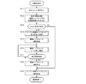
図2は制御装置100による始動時制御のフローチャートである。本フローは、運転者の意思に基づくキーONなどの手動操作によるエンジン始動時に、起動される。本フローの開始と同時に、エンジン1が始動し、オルタネータ15もONとなる。
S1では、空調制御のための各種センサ値を読込む。具体的には、内気温度及び湿度、外気温度及び湿度、日射量、バッテリ電圧等を読込む。
S2では、上記各種センサ値により検出される空調負荷に基づいて、制御目標値を演算する。具体的には、目標吹出し温度、目標ブロワ風量等を演算する。また、電動コンプレッサ11の目標回転数Necも演算する。
S2では、上記各種センサ値により検出される空調負荷に基づいて、制御目標値を演算する。具体的には、目標吹出し温度、目標ブロワ風量等を演算する。また、電動コンプレッサ11の目標回転数Necも演算する。
S3では、電動コンプレッサ11の目標回転数Necと所定回転数とを比較し、Nec≧所定回転数か否かを判定する。ここでの所定回転数は、電動コンプレッサ11がオイル戻し可能な高出力で運転されるか否かを判定するための閾値である。
Nec≧所定回転数の場合は、S4へ進む。
S4では、エンジン駆動コンプレッサ7のクラッチ13を切り、エンジン1の作動にかかわらず、エンジン駆動コンプレッサ7を停止状態に保持する。
S5では、電動コンプレッサ11の運転を開始する。電動コンプレッサ11への給電は、エンジン駆動のオルタネータ15から行い、バッテリ14の電力消費を抑制する。
S4では、エンジン駆動コンプレッサ7のクラッチ13を切り、エンジン1の作動にかかわらず、エンジン駆動コンプレッサ7を停止状態に保持する。
S5では、電動コンプレッサ11の運転を開始する。電動コンプレッサ11への給電は、エンジン駆動のオルタネータ15から行い、バッテリ14の電力消費を抑制する。
S6では、電動コンプレッサ11の運転を継続し、「オイル戻し運転」を実施する。
ここでの「オイル戻し運転」は、空調負荷に応じた回転数(Nec)での運転である。また、空調負荷についても、省エネを狙った制御での負荷ではなく、高出力制御を前提とした負荷とする。例えば、省エネ制御では、エバポレータ出口温度を例えば10℃に設定して制御するが、オイル戻し制御ではエバポレータ出口温度を例えば3℃に設定して制御する。
ここでの「オイル戻し運転」は、空調負荷に応じた回転数(Nec)での運転である。また、空調負荷についても、省エネを狙った制御での負荷ではなく、高出力制御を前提とした負荷とする。例えば、省エネ制御では、エバポレータ出口温度を例えば10℃に設定して制御するが、オイル戻し制御ではエバポレータ出口温度を例えば3℃に設定して制御する。
電動コンプレッサ11のオイル戻し運転中は、S7で、所定時間経過したか否かを判定し、所定時間経過する前は、S6へ戻って、電動コンプレッサ11によるオイル戻し運転を継続する。
所定時間経過した場合は、S7からS8へ進む。
S8では、電動コンプレッサ11の運転を停止する。そして、S9へ進んで、エンジン駆動コンプレッサ7のクラッチ13を接続し、エンジン駆動コンプレッサ7の運転を開始する。
電動コンプレッサ11からエンジン駆動コンプレッサ13への切換えの際は、オルタネータ15によりバッテリ14に充電するバッテリ充電優先モードに移行する。
S8では、電動コンプレッサ11の運転を停止する。そして、S9へ進んで、エンジン駆動コンプレッサ7のクラッチ13を接続し、エンジン駆動コンプレッサ7の運転を開始する。
電動コンプレッサ11からエンジン駆動コンプレッサ13への切換えの際は、オルタネータ15によりバッテリ14に充電するバッテリ充電優先モードに移行する。
一方、S3での判定で、Nec<所定回転数の場合は、S4~S8を実施することなく、S9へ進み、エンジン1の始動と同時にエンジン駆動コンプレッサ7の運転を開始する。 始動時の電動コンプレッサ11の目標回転数Necが所定回転数未満の場合、冷媒流量が足らず、オイルが十分に戻らない可能性がある。このため、電動コンプレッサ11の目標回転数Necが所定回転数以上でなければ、電動コンプレッサ11を運転せず、エンジン駆動コンプレッサ7を運転するのである。
S9でのエンジン駆動コンプレッサ7の運転開始後は、通常制御へ移行する。
図3は通常制御でのコンプレッサ切換制御ルーチンのフローチャートである。
S11では、アイドルストップ中か否かを判定する。
アイドルストップ中でない場合、すなわち、エンジン運転中の場合は、S12へ進む。
S12では、電動コンプレッサ11を停止し、エンジン駆動コンプレッサ7を使用する(クラッチ13はON)。
アイドルストップ中の場合、すなわち、エンジン停止時の場合は、S13へ進む。
S13では、エンジン駆動コンプレッサ7は停止するので、電動コンプレッサ11を使用する。
S11では、アイドルストップ中か否かを判定する。
アイドルストップ中でない場合、すなわち、エンジン運転中の場合は、S12へ進む。
S12では、電動コンプレッサ11を停止し、エンジン駆動コンプレッサ7を使用する(クラッチ13はON)。
アイドルストップ中の場合、すなわち、エンジン停止時の場合は、S13へ進む。
S13では、エンジン駆動コンプレッサ7は停止するので、電動コンプレッサ11を使用する。
本実施形態によれば、エンジン駆動コンプレッサ7と、電動コンプレッサ11とを備え、エンジン作動時にはエンジン駆動コンプレッサ7を使用し、エンジン停止時には電動コンプレッサ11を使用する。このため、エンジン停止時においても冷媒を循環させて、冷房を行うことができる。
本実施形態によれば、エンジン始動時には、エンジン駆動コンプレッサ7を停止状態に保持しつつ、電動コンプレッサ11を所定時間作動させ、その後にエンジン駆動コンプレッサ7を作動させる。これにより、電動コンプレッサ11にオイルを回収することが可能となり、電動コンプレッサ11内のオイルを確保して、耐久性の低下を抑制することができる。
すなわち、冷房が必要となる夏季などにおいて、エンジン始動時、特にキーONなどの手動操作によるエンジン始動時は、車室内が熱くなっているなどの理由により、空調装置が高出力を要求される。従って、このときに一時的に、エンジン駆動コンプレッサ7を作動させずに、電動コンプレッサ11を作動させることで、電動コンプレッサ11に高出力で運転する機会を与えることができる。これにより、電動コンプレッサ11にオイルを回収することが可能となり、電動コンプレッサ11の耐久性向上を見込める。
すなわち、冷房が必要となる夏季などにおいて、エンジン始動時、特にキーONなどの手動操作によるエンジン始動時は、車室内が熱くなっているなどの理由により、空調装置が高出力を要求される。従って、このときに一時的に、エンジン駆動コンプレッサ7を作動させずに、電動コンプレッサ11を作動させることで、電動コンプレッサ11に高出力で運転する機会を与えることができる。これにより、電動コンプレッサ11にオイルを回収することが可能となり、電動コンプレッサ11の耐久性向上を見込める。
また、本実施形態によれば、エンジン始動時に電動コンプレッサ11を作動させる際は、電動コンプレッサ11を空調負荷に応じた回転数(Nec)で作動させる。これにより、電動コンプレッサ11に高出力で運転する機会を確実に与えることができる。
また、本実施形態によれば、前記空調負荷に応じた回転数(Nec)が所定回転数未満の場合は、エンジン始動時に電動コンプレッサ11を作動させず、エンジン駆動コンプレッサ7を作動させる。この場合は、冷媒流量が不足して、オイルが十分に戻らない可能性が高いため、バッテリ電力の無駄な消費を抑制するのである。
尚、上記の説明では、電動コンプレッサ11へのオイル戻しのため、キーONなどの手動操作によるエンジン始動時に、電動コンプレッサ11を所定時間作動させる構成としたが、これに加え、アイドルストップ状態からエンジンを自動的に始動させる際にも、電動コンプレッサ11を所定時間作動させる構成としてもよい。
また、キーONなどの手動操作によるエンジン始動には、キーレスシステムにおいて各種のスタートボタンなどを用いて行うエンジン始動を含むものであることは言うまでもない。
また、キーONなどの手動操作によるエンジン始動には、キーレスシステムにおいて各種のスタートボタンなどを用いて行うエンジン始動を含むものであることは言うまでもない。
また、図示の実施形態はあくまで本発明を例示するものであり、本発明は、説明した実施形態により直接的に示されるものに加え、特許請求の範囲内で当業者によりなされる各種の改良・変更を包含するものであることは言うまでもない。
1 エンジン
2 HVACユニット
3 ブロア
4 エバポレータ
5 ヒータコア
6 冷媒循環回路
7 エンジン駆動コンプレッサ
8 コンデンサ
9 受液器
10 膨張弁
11 電動コンプレッサ
12 ベルト
13 クラッチ
14 バッテリ
15 オルタネータ
16 エンジン冷却水回路
17 ラジエータ
100 制御装置
2 HVACユニット
3 ブロア
4 エバポレータ
5 ヒータコア
6 冷媒循環回路
7 エンジン駆動コンプレッサ
8 コンデンサ
9 受液器
10 膨張弁
11 電動コンプレッサ
12 ベルト
13 クラッチ
14 バッテリ
15 オルタネータ
16 エンジン冷却水回路
17 ラジエータ
100 制御装置
Claims (4)
- エンジン駆動と電動機駆動の2機のコンプレッサと、これらのコンプレッサの作動を制御する制御装置とを備え、エンジン作動時にはエンジン駆動コンプレッサを使用し、エンジン停止時には電動機駆動コンプレッサを使用する、車両用空調装置において、
前記制御装置は、エンジン始動時には、エンジン駆動コンプレッサを停止状態に保持しつつ、電動機駆動コンプレッサを所定時間作動させ、その後にエンジン駆動コンプレッサを作動させるように構成されていることを特徴とする、車両用空調装置。 - 前記制御装置は、エンジン始動時に電動機駆動コンプレッサを作動させる際は、電動機駆動コンプレッサを空調負荷に応じた回転数で作動させることを特徴とする、請求項1記載の車両用空調装置。
- 前記制御装置は、前記空調負荷に応じた回転数が所定回転数未満の場合は、エンジン始動時に電動機駆動コンプレッサを作動させず、エンジン駆動コンプレッサを作動させることを特徴とする、請求項2記載の車両用空調装置。
- 所定のアイドルストップ条件にてエンジンを自動的に停止させるアイドルストップ車両に適用され、
前記電動機駆動コンプレッサを所定時間作動させるエンジン始動時は、手動操作によるエンジン始動時であることを特徴とする、請求項1~請求項3のいずれか1つに記載の車両用空調装置。
Priority Applications (1)
| Application Number | Priority Date | Filing Date | Title |
|---|---|---|---|
| US15/324,784 US10183554B2 (en) | 2014-07-10 | 2015-03-17 | Vehicular air conditioning device |
Applications Claiming Priority (2)
| Application Number | Priority Date | Filing Date | Title |
|---|---|---|---|
| JP2014142448A JP6368180B2 (ja) | 2014-07-10 | 2014-07-10 | 車両用空調装置 |
| JP2014-142448 | 2014-07-10 |
Publications (1)
| Publication Number | Publication Date |
|---|---|
| WO2016006278A1 true WO2016006278A1 (ja) | 2016-01-14 |
Family
ID=55063924
Family Applications (1)
| Application Number | Title | Priority Date | Filing Date |
|---|---|---|---|
| PCT/JP2015/057792 Ceased WO2016006278A1 (ja) | 2014-07-10 | 2015-03-17 | 車両用空調装置 |
Country Status (3)
| Country | Link |
|---|---|
| US (1) | US10183554B2 (ja) |
| JP (1) | JP6368180B2 (ja) |
| WO (1) | WO2016006278A1 (ja) |
Cited By (4)
| Publication number | Priority date | Publication date | Assignee | Title |
|---|---|---|---|---|
| US20200254849A1 (en) * | 2016-01-25 | 2020-08-13 | Tiger Tool International Incorporated | Vehicle air conditioning systems and methods employing rotary engine driven compressor |
| US11407283B2 (en) | 2018-04-30 | 2022-08-09 | Tiger Tool International Incorporated | Cab heating systems and methods for vehicles |
| US11993130B2 (en) | 2018-11-05 | 2024-05-28 | Tiger Tool International Incorporated | Cooling systems and methods for vehicle cabs |
| US12030368B2 (en) | 2020-07-02 | 2024-07-09 | Tiger Tool International Incorporated | Compressor systems and methods for use by vehicle heating, ventilating, and air conditioning systems |
Families Citing this family (7)
| Publication number | Priority date | Publication date | Assignee | Title |
|---|---|---|---|---|
| US7192347B1 (en) * | 2001-11-06 | 2007-03-20 | Bally Gaming, Inc. | Game machine having a plurality of ways for a user to obtain payouts based on the appearance of any and all symbols within an active symbol matrix (“what you see is what you get”) |
| WO2017006452A1 (ja) * | 2015-07-08 | 2017-01-12 | 三菱電機株式会社 | 空気調和装置 |
| EP3440418B1 (en) | 2016-04-05 | 2026-01-07 | Carrier Corporation | Tractor trailer system |
| CA3079079A1 (en) * | 2017-11-17 | 2019-05-23 | Autoclima S.P.A. | Air conditioning kit for vehicles |
| CA3079080A1 (en) * | 2017-11-17 | 2019-05-23 | Autoclima S.P.A. | Air conditioning system for vehicles |
| US12097753B2 (en) * | 2018-09-11 | 2024-09-24 | Magna Pt B.V. & Co. Kg | Electric vehicle air conditioning system and method |
| JP7280770B2 (ja) * | 2019-07-29 | 2023-05-24 | サンデン株式会社 | 車両用空気調和装置 |
Citations (4)
| Publication number | Priority date | Publication date | Assignee | Title |
|---|---|---|---|---|
| JPS6261819A (ja) * | 1985-09-10 | 1987-03-18 | Nippon Denso Co Ltd | 冷房装置 |
| JP2003042073A (ja) * | 2001-05-22 | 2003-02-13 | Denso Corp | 車両用冷房装置 |
| JP2003205731A (ja) * | 2001-05-30 | 2003-07-22 | Denso Corp | 車両用空調装置 |
| JP2004237907A (ja) * | 2003-02-07 | 2004-08-26 | Sanyo Electric Co Ltd | 自動車用空調システム |
Family Cites Families (3)
| Publication number | Priority date | Publication date | Assignee | Title |
|---|---|---|---|---|
| JP3151452B2 (ja) * | 1999-01-08 | 2001-04-03 | 株式会社ゼクセルヴァレオクライメートコントロール | ハイブリッドコンプレッサの制御装置 |
| US6637230B2 (en) | 2001-04-27 | 2003-10-28 | Denso Corporation | Automotive air-conditioner having sub-compressor driven by electric motor |
| JP2005201483A (ja) * | 2004-01-13 | 2005-07-28 | Denso Corp | 冷凍装置およびその冷凍装置の運転制御方法 |
-
2014
- 2014-07-10 JP JP2014142448A patent/JP6368180B2/ja active Active
-
2015
- 2015-03-17 WO PCT/JP2015/057792 patent/WO2016006278A1/ja not_active Ceased
- 2015-03-17 US US15/324,784 patent/US10183554B2/en active Active
Patent Citations (4)
| Publication number | Priority date | Publication date | Assignee | Title |
|---|---|---|---|---|
| JPS6261819A (ja) * | 1985-09-10 | 1987-03-18 | Nippon Denso Co Ltd | 冷房装置 |
| JP2003042073A (ja) * | 2001-05-22 | 2003-02-13 | Denso Corp | 車両用冷房装置 |
| JP2003205731A (ja) * | 2001-05-30 | 2003-07-22 | Denso Corp | 車両用空調装置 |
| JP2004237907A (ja) * | 2003-02-07 | 2004-08-26 | Sanyo Electric Co Ltd | 自動車用空調システム |
Cited By (5)
| Publication number | Priority date | Publication date | Assignee | Title |
|---|---|---|---|---|
| US20200254849A1 (en) * | 2016-01-25 | 2020-08-13 | Tiger Tool International Incorporated | Vehicle air conditioning systems and methods employing rotary engine driven compressor |
| US11135892B2 (en) * | 2016-01-25 | 2021-10-05 | Tiger Tool International Incorporated | Vehicle air conditioning systems and methods employing rotary engine driven compressor |
| US11407283B2 (en) | 2018-04-30 | 2022-08-09 | Tiger Tool International Incorporated | Cab heating systems and methods for vehicles |
| US11993130B2 (en) | 2018-11-05 | 2024-05-28 | Tiger Tool International Incorporated | Cooling systems and methods for vehicle cabs |
| US12030368B2 (en) | 2020-07-02 | 2024-07-09 | Tiger Tool International Incorporated | Compressor systems and methods for use by vehicle heating, ventilating, and air conditioning systems |
Also Published As
| Publication number | Publication date |
|---|---|
| US20170197492A1 (en) | 2017-07-13 |
| US10183554B2 (en) | 2019-01-22 |
| JP2016016821A (ja) | 2016-02-01 |
| JP6368180B2 (ja) | 2018-08-01 |
Similar Documents
| Publication | Publication Date | Title |
|---|---|---|
| JP6368180B2 (ja) | 車両用空調装置 | |
| JP6192434B2 (ja) | 車両用空気調和装置 | |
| JP6167892B2 (ja) | 車両用空調装置 | |
| US9242532B2 (en) | Air conditioner system control method for vehicle | |
| JP6233009B2 (ja) | 車両用空調装置 | |
| CN104822551B (zh) | 车辆用空调装置 | |
| JP6040099B2 (ja) | 車両用空気調和装置 | |
| CN105246718B (zh) | 车用空调装置 | |
| JP4475436B2 (ja) | 車両の制御装置 | |
| JP2003326962A (ja) | 車両用空調装置 | |
| CN102918268B (zh) | 用于空调回路的混合动力压缩机 | |
| EP2014491A1 (en) | Control apparatus for vehicle air conditioner | |
| JP6197642B2 (ja) | 車両用空調装置 | |
| WO1998015420A1 (en) | Air conditioning apparatus for vehicle | |
| US5385028A (en) | Method of odor elimination on A/C heat pump systems | |
| JP5925048B2 (ja) | 車両用空調装置及び車両 | |
| JP2006199247A (ja) | 車両用空調装置 | |
| JP5195378B2 (ja) | 車両用空調制御装置 | |
| JP3858738B2 (ja) | 車両用空気調和装置 | |
| JP6357374B2 (ja) | 車両用空調装置 | |
| JP2010281229A (ja) | 内燃機関の自動停止始動制御装置 | |
| JP2003146061A (ja) | 自動車用空調システム | |
| JP2003211951A (ja) | 車両用空調装置 | |
| JP2023167294A (ja) | 車両の空調制御システム | |
| KR20120013746A (ko) | 에어컨 작동이 가능한 공회전 제한 장치 |
Legal Events
| Date | Code | Title | Description |
|---|---|---|---|
| 121 | Ep: the epo has been informed by wipo that ep was designated in this application |
Ref document number: 15819350 Country of ref document: EP Kind code of ref document: A1 |
|
| WWE | Wipo information: entry into national phase |
Ref document number: 15324784 Country of ref document: US |
|
| NENP | Non-entry into the national phase |
Ref country code: DE |
|
| 122 | Ep: pct application non-entry in european phase |
Ref document number: 15819350 Country of ref document: EP Kind code of ref document: A1 |