WO2016002830A1 - Dispositif de haut-parleur - Google Patents
Dispositif de haut-parleur Download PDFInfo
- Publication number
- WO2016002830A1 WO2016002830A1 PCT/JP2015/068952 JP2015068952W WO2016002830A1 WO 2016002830 A1 WO2016002830 A1 WO 2016002830A1 JP 2015068952 W JP2015068952 W JP 2015068952W WO 2016002830 A1 WO2016002830 A1 WO 2016002830A1
- Authority
- WO
- WIPO (PCT)
- Prior art keywords
- voice coil
- coil pattern
- noise
- voice
- signal
- Prior art date
Links
Images


Classifications
-
- H—ELECTRICITY
- H04—ELECTRIC COMMUNICATION TECHNIQUE
- H04R—LOUDSPEAKERS, MICROPHONES, GRAMOPHONE PICK-UPS OR LIKE ACOUSTIC ELECTROMECHANICAL TRANSDUCERS; DEAF-AID SETS; PUBLIC ADDRESS SYSTEMS
- H04R9/00—Transducers of moving-coil, moving-strip, or moving-wire type
- H04R9/06—Loudspeakers
- H04R9/063—Loudspeakers using a plurality of acoustic drivers
-
- G—PHYSICS
- G10—MUSICAL INSTRUMENTS; ACOUSTICS
- G10K—SOUND-PRODUCING DEVICES; METHODS OR DEVICES FOR PROTECTING AGAINST, OR FOR DAMPING, NOISE OR OTHER ACOUSTIC WAVES IN GENERAL; ACOUSTICS NOT OTHERWISE PROVIDED FOR
- G10K11/00—Methods or devices for transmitting, conducting or directing sound in general; Methods or devices for protecting against, or for damping, noise or other acoustic waves in general
- G10K11/16—Methods or devices for protecting against, or for damping, noise or other acoustic waves in general
- G10K11/175—Methods or devices for protecting against, or for damping, noise or other acoustic waves in general using interference effects; Masking sound
- G10K11/178—Methods or devices for protecting against, or for damping, noise or other acoustic waves in general using interference effects; Masking sound by electro-acoustically regenerating the original acoustic waves in anti-phase
- G10K11/1785—Methods, e.g. algorithms; Devices
- G10K11/17855—Methods, e.g. algorithms; Devices for improving speed or power requirements
-
- G—PHYSICS
- G10—MUSICAL INSTRUMENTS; ACOUSTICS
- G10K—SOUND-PRODUCING DEVICES; METHODS OR DEVICES FOR PROTECTING AGAINST, OR FOR DAMPING, NOISE OR OTHER ACOUSTIC WAVES IN GENERAL; ACOUSTICS NOT OTHERWISE PROVIDED FOR
- G10K11/00—Methods or devices for transmitting, conducting or directing sound in general; Methods or devices for protecting against, or for damping, noise or other acoustic waves in general
- G10K11/16—Methods or devices for protecting against, or for damping, noise or other acoustic waves in general
- G10K11/175—Methods or devices for protecting against, or for damping, noise or other acoustic waves in general using interference effects; Masking sound
- G10K11/178—Methods or devices for protecting against, or for damping, noise or other acoustic waves in general using interference effects; Masking sound by electro-acoustically regenerating the original acoustic waves in anti-phase
- G10K11/1787—General system configurations
- G10K11/17873—General system configurations using a reference signal without an error signal, e.g. pure feedforward
-
- H—ELECTRICITY
- H04—ELECTRIC COMMUNICATION TECHNIQUE
- H04R—LOUDSPEAKERS, MICROPHONES, GRAMOPHONE PICK-UPS OR LIKE ACOUSTIC ELECTROMECHANICAL TRANSDUCERS; DEAF-AID SETS; PUBLIC ADDRESS SYSTEMS
- H04R7/00—Diaphragms for electromechanical transducers; Cones
- H04R7/02—Diaphragms for electromechanical transducers; Cones characterised by the construction
- H04R7/04—Plane diaphragms
-
- H—ELECTRICITY
- H04—ELECTRIC COMMUNICATION TECHNIQUE
- H04R—LOUDSPEAKERS, MICROPHONES, GRAMOPHONE PICK-UPS OR LIKE ACOUSTIC ELECTROMECHANICAL TRANSDUCERS; DEAF-AID SETS; PUBLIC ADDRESS SYSTEMS
- H04R9/00—Transducers of moving-coil, moving-strip, or moving-wire type
- H04R9/02—Details
- H04R9/025—Magnetic circuit
-
- H—ELECTRICITY
- H04—ELECTRIC COMMUNICATION TECHNIQUE
- H04R—LOUDSPEAKERS, MICROPHONES, GRAMOPHONE PICK-UPS OR LIKE ACOUSTIC ELECTROMECHANICAL TRANSDUCERS; DEAF-AID SETS; PUBLIC ADDRESS SYSTEMS
- H04R9/00—Transducers of moving-coil, moving-strip, or moving-wire type
- H04R9/02—Details
- H04R9/04—Construction, mounting, or centering of coil
- H04R9/046—Construction
- H04R9/047—Construction in which the windings of the moving coil lay in the same plane
-
- G—PHYSICS
- G10—MUSICAL INSTRUMENTS; ACOUSTICS
- G10K—SOUND-PRODUCING DEVICES; METHODS OR DEVICES FOR PROTECTING AGAINST, OR FOR DAMPING, NOISE OR OTHER ACOUSTIC WAVES IN GENERAL; ACOUSTICS NOT OTHERWISE PROVIDED FOR
- G10K2210/00—Details of active noise control [ANC] covered by G10K11/178 but not provided for in any of its subgroups
- G10K2210/30—Means
- G10K2210/301—Computational
- G10K2210/3044—Phase shift, e.g. complex envelope processing
-
- H—ELECTRICITY
- H04—ELECTRIC COMMUNICATION TECHNIQUE
- H04R—LOUDSPEAKERS, MICROPHONES, GRAMOPHONE PICK-UPS OR LIKE ACOUSTIC ELECTROMECHANICAL TRANSDUCERS; DEAF-AID SETS; PUBLIC ADDRESS SYSTEMS
- H04R1/00—Details of transducers, loudspeakers or microphones
- H04R1/005—Details of transducers, loudspeakers or microphones using digitally weighted transducing elements
-
- H—ELECTRICITY
- H04—ELECTRIC COMMUNICATION TECHNIQUE
- H04R—LOUDSPEAKERS, MICROPHONES, GRAMOPHONE PICK-UPS OR LIKE ACOUSTIC ELECTROMECHANICAL TRANSDUCERS; DEAF-AID SETS; PUBLIC ADDRESS SYSTEMS
- H04R1/00—Details of transducers, loudspeakers or microphones
- H04R1/10—Earpieces; Attachments therefor ; Earphones; Monophonic headphones
- H04R1/1083—Reduction of ambient noise
-
- H—ELECTRICITY
- H04—ELECTRIC COMMUNICATION TECHNIQUE
- H04R—LOUDSPEAKERS, MICROPHONES, GRAMOPHONE PICK-UPS OR LIKE ACOUSTIC ELECTROMECHANICAL TRANSDUCERS; DEAF-AID SETS; PUBLIC ADDRESS SYSTEMS
- H04R2207/00—Details of diaphragms or cones for electromechanical transducers or their suspension covered by H04R7/00 but not provided for in H04R7/00 or in H04R2307/00
-
- H—ELECTRICITY
- H04—ELECTRIC COMMUNICATION TECHNIQUE
- H04R—LOUDSPEAKERS, MICROPHONES, GRAMOPHONE PICK-UPS OR LIKE ACOUSTIC ELECTROMECHANICAL TRANSDUCERS; DEAF-AID SETS; PUBLIC ADDRESS SYSTEMS
- H04R2460/00—Details of hearing devices, i.e. of ear- or headphones covered by H04R1/10 or H04R5/033 but not provided for in any of their subgroups, or of hearing aids covered by H04R25/00 but not provided for in any of its subgroups
- H04R2460/01—Hearing devices using active noise cancellation
-
- H—ELECTRICITY
- H04—ELECTRIC COMMUNICATION TECHNIQUE
- H04R—LOUDSPEAKERS, MICROPHONES, GRAMOPHONE PICK-UPS OR LIKE ACOUSTIC ELECTROMECHANICAL TRANSDUCERS; DEAF-AID SETS; PUBLIC ADDRESS SYSTEMS
- H04R7/00—Diaphragms for electromechanical transducers; Cones
- H04R7/02—Diaphragms for electromechanical transducers; Cones characterised by the construction
- H04R7/04—Plane diaphragms
- H04R7/06—Plane diaphragms comprising a plurality of sections or layers
Definitions
- the present invention relates to a speaker device.
- noise canceling technique that cancels external noise so that only a musical sound can be heard by a user's ear has been widespread.
- This noise cancellation technology detects external noise with a microphone, generates a noise cancellation signal having a phase opposite to the detected noise signal, and outputs the noise cancellation signal from a speaker device or the like, thereby canceling the noise. .
- a speaker unit including one diaphragm and two voice coils for driving the diaphragm is provided, and a musical tone signal is transmitted to one voice coil and the other voice coil is coupled to the other voice coil.
- a noise cancellation signal based on a noise signal detected by a noise detection microphone is input (see Patent Document 1).
- Patent Document 1 since a noise cancel signal is input to one of two voice coils wound with two coils to drive one diaphragm and cancel the noise, a noise cancel signal is used. The delay with respect to actual noise can be reduced as much as possible.
- the thing of the said patent document 1 is applied to a normal dynamic type speaker, and the diaphragm of a speaker apparatus and the dead weight of a voice coil part increase by increasing a voice coil, Therefore The vibration of a diaphragm is suppressed. Therefore, there is a problem that the high frequency characteristics are hindered and the acoustic characteristics are deteriorated.
- the present invention has been made in view of the above points, and can prevent time lag between an audio signal and a noise cancellation signal, and can improve acoustic characteristics by avoiding deterioration of high frequency characteristics.
- An object of the present invention is to provide a speaker device.
- the present invention provides a speaker device including a flat diaphragm, wherein the flat diaphragm is formed corresponding to a magnetic field formed by a magnet and supplied with a driving current based on an audio signal.
- a voice coil pattern is provided, and a noise canceling voice coil pattern to which a drive current based on a noise cancellation signal is supplied is provided.
- the planar diaphragm may have a configuration in which the voice voice coil pattern and the noise canceling voice coil pattern are formed on a flexible wiring board. Further, in the above configuration, the noise canceling voice coil pattern may be formed on one side of the voice voice coil pattern. Moreover, the said structure WHEREIN: The said noise cancellation voice coil pattern is good also as a structure currently formed in the both sides of the said voice voice coil pattern.
- a plurality of the noise canceling voice coil patterns are formed, and one end of each noise canceling voice coil pattern is electrically connected to form one noise canceling voice coil pattern. It is good.
- the said structure WHEREIN It is good also as a structure which connected the resistive element to the middle part of the said voice coil pattern for noise cancellation.
- a reinforcing pattern may be formed between the voice voice coil pattern or the noise canceling voice coil pattern of the planar diaphragm.
- the voice voice coil pattern to which the driving current based on the audio signal is supplied and the noise canceling voice coil pattern to which the driving current based on the noise cancellation signal is supplied are formed.
- the audio signal is not affected by the noise signal, and a reproduced sound with good sound quality can be obtained.
- the voice voice coil pattern and the noise canceling voice coil pattern are formed, the surface of the diaphragm can be hardened. Therefore, the transmission speed by the diaphragm can be increased, and deterioration of the high frequency characteristics can be avoided.
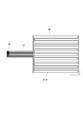
- FIG. 1 is an exploded perspective view of a speaker device showing a first embodiment of the speaker device according to the present invention.
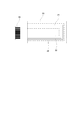
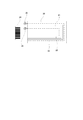
- FIG. 2 is a longitudinal sectional view of the speaker device.
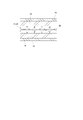
- FIG. 3 is a plan view of the diaphragm.
- FIG. 4 is an enlarged view of a part of the diaphragm in the one-dot chain line frame portion of FIG. 3.
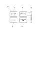
- FIG. 5 is a block diagram of the drive circuit.
- FIG. 6 is an enlarged view of a part of a diaphragm showing a second embodiment of the speaker device according to the present invention.
- FIG. 7 is an enlarged view of a part of a diaphragm showing a third embodiment of the speaker device according to the present invention.
- FIG. 1 is an exploded perspective view of a speaker device showing a first embodiment of the speaker device according to the present invention.
- FIG. 2 is a longitudinal sectional view of the speaker device.
- FIG. 3 is a plan view of the diaphragm
- FIG. 8 is an enlarged view of a part of a diaphragm showing a fourth embodiment of the speaker device according to the present invention.
- FIG. 9 is an enlarged view of a part of a diaphragm showing a fifth embodiment of the speaker device according to the present invention.
- FIG. 1 is an exploded perspective view of the speaker device
- FIG. 2 is a longitudinal sectional view of the speaker device
- FIG. 3 is a plan view of the diaphragm
- FIG. 4 is an enlarged view of a part of the diaphragm in the one-dot chain line frame portion of FIG.
- the speaker device is an example of a full digital speaker device using a planar diaphragm.
- the speaker device 10 includes a diaphragm 11, a pair of magnets 13 and 13 that sandwich the diaphragm 11 from above and below via cushioning members 12 and 12, and a pair of these members covering the whole from above and below. Holding members 14, 14.
- the diaphragm 11 is composed of a thin film-like flexible wiring board 20, and a voice voice coil pattern 21 to which a drive current is supplied based on a voice signal is formed on one surface of the flexible wiring board 20. ing. As shown in FIGS. 3 and 4, the voice voice coil pattern 21 is formed so that a plurality of conductive wire patterns meander over the entire area of the flexible wiring board 20.
- the flexible wiring board 20 has one noise canceling voice coil pattern 22 on one side of the voice voice coil pattern 21, and the voice voice coil pattern 21. And meandering so as to be substantially parallel to the line. 4 and 6 to 9, for convenience of explanation, the voice voice coil pattern 21 is indicated by a solid line, and the noise canceling voice coil pattern 22 is indicated by a one-dot chain line.
- a lead wire drawing portion 23 is provided integrally with the voice voice coil pattern 21 and the noise canceling voice coil pattern 22.
- the lead wire drawing portion 23 is provided at the tip of the lead wire drawing portion 23.
- terminal portions 24 respectively connected to the end portions of the voice voice coil pattern 21 and the noise canceling voice coil pattern 22.
- a drive current is supplied from the terminal unit 24 based on a predetermined digital audio signal and an analog noise cancellation signal.
- the magnets 13 are formed in parallel stripes so that the N poles and the S poles are alternately positioned along the line on which the voice coil pattern is formed.
- the magnetic field component perpendicular to the surface of the magnet 13 is the largest in the vicinity of the N pole and the S pole, and the smallest in the vicinity of the boundary between the N pole and the S pole.
- the horizontal magnetic field component parallel to the surface of the magnet 13 is the smallest in the vicinity of the N pole and the S pole, and the largest in the vicinity of the boundary between the N pole and the S pole. Therefore, the magnetic field component that contributes to vibrating the diaphragm 11 in the thickness direction is not a vertical component but a horizontal component (Fleming's left-hand rule).
- the voice voice coil within the plane of the diaphragm 11 is provided by arranging the linear portions of the voice voice coil pattern 21 and the noise canceling voice coil pattern 22 at positions corresponding to the vicinity of the boundary between the N pole and the S pole. Magnetic lines of force pass through the pattern 21 and the noise canceling voice coil pattern 22 so as to cross the straight line portion. Therefore, in this embodiment, the voice voice coil pattern 21 and the noise canceling voice coil pattern 22 are arranged at the boundary between the N pole and the S pole.
- a driving current is applied to the voice voice coil pattern 21 and the noise canceling voice coil pattern 22
- an electromagnetic force is generated most efficiently due to the interaction between the current and the magnetic field, and the diaphragm 11 moves in the thickness direction. It is configured to vibrate.
- the magnet 13 is formed with a plurality of through holes 25 through which sound output from the diaphragm 11 is passed.
- the voice voice coil pattern 21 and the noise canceling voice coil pattern 22 are arranged at the boundary portion between the N pole and the S pole, and the diaphragm 11 is vibrated efficiently at the boundary portion. Therefore, the through hole 25 is preferably formed at a position corresponding to a boundary portion between the N pole and the S pole.
- the buffer member 12 is made of a soft material and has a function of passing sound, and is made of, for example, a nonwoven fabric.
- the buffer member 12 is formed to have substantially the same size as the diaphragm 11, and the buffer member 12 is configured so that a predetermined gap is formed between the diaphragm 11 and the magnet 13. Yes.
- the buffer member 12 prevents the diaphragm 11 from colliding with the magnet 13 and generating an abnormal noise when the diaphragm 11 is driven.
- the buffer member 12 may include a plurality of buffer members 12 depending on its thickness and material. It can also be used in layers.
- the holding member 14 is made of, for example, a hard material such as metal, and is illustrated on the outer periphery of the holding member 14 with the diaphragm 11, the buffer member 12, and the magnet 13 sandwiched between the holding members 14.
- the diaphragm 11 is fixed so as to be held between the pair of magnets 13 with a predetermined gap by screwing screws that are not to be engaged.
- the holding member 14 is formed with a through hole 26 at the same position as the through hole 25 of the magnet 13, and the through hole 26 can efficiently radiate sound from the diaphragm 11 to the outside. It is configured to be able to.
- the drive circuit 30 includes an audio driver circuit 32 to which a digital audio signal from a predetermined digital sound source 31 is input.
- the audio driver circuit 32 converts the digital audio signal into a predetermined audio drive signal.
- the driving current based on the voice driving signal is supplied to the voice voice coil pattern 21 via the terminal unit 24.
- the drive circuit 30 includes a microphone 33 that inputs external noise, and the drive circuit 30 includes a noise cancellation circuit 34 that inputs an external noise signal from the microphone 33.
- the noise cancellation circuit 34 inverts the phase of the noise signal from the microphone 33, uses the inverted signal as a noise cancellation signal, and a drive current based on the noise cancellation signal is connected to the noise cancellation voice coil pattern via the terminal unit 24. 22 is configured to be supplied.
- an audio signal sent from a predetermined digital sound source 31 is used as an audio drive signal by the audio driver circuit 32, and a drive current based on this audio drive signal is supplied to the audio voice coil pattern 21.
- external noise is input by the microphone 33 and sent to the noise cancellation circuit 34.
- the noise cancellation circuit 34 inverts the phase of the noise signal from the microphone 33, and noise cancels the drive current based on the phase-inverted noise cancellation signal.
- the voice coil pattern 22 is supplied.
- the voice coil pattern 21 and the noise canceling voice coil pattern 22 are formed on the flexible wiring board 20, and the driving current based on the noise canceling signal together with the driving current based on the sound signal. Therefore, the diaphragm 11 is vibrated on the basis of a signal obtained by synthesizing these sound signal and noise cancel signal, and the sound by the sound signal is reduced in a state where external noise is canceled. It can be output. As a result, the audio signal is not affected by the noise signal, and a reproduced sound with good sound quality can be obtained.
- the noise canceling voice coil pattern 22 is formed on the flexible wiring board 20 in addition to the voice voice coil pattern 21, only the amount of the noise canceling voice coil pattern 22 increased. The surface of the diaphragm 11 can be hardened. Therefore, the transmission speed by the diaphragm 11 can be increased, and deterioration of the high frequency characteristics can be avoided.
- FIG. 6 shows a second embodiment of the present invention.
- the noise canceling voice coil pattern 22 is formed on both sides of the voice voice coil pattern 21 formed on the flexible wiring board 20.
- the noise canceling voice coil pattern 22 is formed on one side of the voice voice coil pattern 21, but the noise canceling is performed on one side of the voice voice coil pattern 21.
- the voice coil pattern 22 is formed, the amplitude of the diaphragm 11 may be nonuniform. Therefore, in the present embodiment, the noise canceling voice coil pattern 22 is formed on both sides of the voice voice coil pattern 21 so that the diaphragm 11 can be caused to vibrate uniformly with respect to the voice voice coil pattern 21. Is.
- the voice voice coil pattern 21 and the noise canceling voice coil pattern 22 are formed on the flexible wiring board 20, and the noise canceling signal is generated together with the driving current based on the sound signal. Therefore, the diaphragm 11 is vibrated based on a signal obtained by synthesizing the sound signal and the noise cancellation signal, and the sound signal is canceled in a state in which the external noise is canceled. Can output sound. Further, since the noise canceling voice coil pattern 22 is formed on both sides of the voice voice coil pattern 21 on the flexible wiring board 20, the surface of the diaphragm 11 is made harder than in the first embodiment. Therefore, the transmission speed by the diaphragm 11 can be increased, and the deterioration of the high frequency characteristics can be avoided.
- FIG. 7 shows a third embodiment of the present invention.
- a speaker device using the planar diaphragm 11 tends to have lower impedance and higher current consumption than a dynamic speaker device.
- the noise canceling voice coil pattern 22 is formed on both sides of the voice voice coil pattern 21 as in the second embodiment, and the end portions of the noise canceling voice coil patterns 22 are formed. By electrically connecting, one long noise canceling voice coil pattern 22 disposed on both sides of the voice voice coil pattern 21 is formed.
- the length of the noise canceling voice coil pattern 22 is formed to be long, so that the resistance value of the noise canceling voice coil pattern 22 is increased, so that the impedance of the noise canceling voice coil pattern 22 can be increased. It becomes.
- the voice coil pattern 21 and the noise canceling voice coil pattern 22 are formed on the flexible wiring board 20, and the drive currents based on the sound signal and the noise canceling signal are respectively supplied. Therefore, the diaphragm 11 is vibrated based on a signal obtained by synthesizing the audio signal and the noise cancellation signal, and the audio signal is output in a state where external noise is canceled. It is something that can be done. Further, since the voice voice coil pattern 21 and the noise canceling voice coil pattern 22 are formed on the flexible wiring board 20, the surface of the diaphragm 11 can be hardened, and the transmission speed of the diaphragm 11 can be increased. It can be increased, and deterioration of the high frequency characteristics can be avoided.
- the end portion of the noise canceling voice coil pattern 22 is electrically connected so that the length of the noise canceling voice coil pattern 22 is increased, the resistance value of the noise canceling voice coil pattern 22 is increased. Therefore, the impedance of the noise canceling voice coil pattern 22 can be increased, and as a result, the current consumption can be reduced, thereby preventing the overcurrent protection circuit from functioning. it can.
- the wiring pattern of the noise canceling voice coil pattern 22 By devising the wiring pattern of the noise canceling voice coil pattern 22, it is possible to ensure a long length of the noise canceling voice coil pattern 22.
- the impedance of the noise canceling voice coil pattern 22 can be increased.
- the impedance of the noise canceling voice coil pattern 22 can be easily increased without devising such a wiring pattern. It can be increased.
- FIG. 8 shows a fourth embodiment of the present invention.
- the noise canceling voice coil pattern 22 is formed on both sides of the voice voice coil pattern 21, and each of these noise canceling voice coil patterns 22 is also formed.
- the resistance element 35 is connected to the middle part.
- the voice coil pattern 21 and the noise canceling voice coil pattern 22 are formed on the flexible wiring board 20, and the drive currents based on the sound signal and the noise canceling signal are respectively supplied. Therefore, the diaphragm 11 is vibrated based on a signal obtained by synthesizing the audio signal and the noise cancellation signal, and the audio signal is output in a state where external noise is canceled. It is something that can be done. Further, since the voice voice coil pattern 21 and the noise canceling voice coil pattern 22 are formed on the flexible wiring board 20, the surface of the diaphragm 11 can be hardened, and the transmission speed of the diaphragm 11 can be increased. It can be increased, and deterioration of the high frequency characteristics can be avoided.
- the resistance element 35 Since the resistance element 35 is connected to the middle part of the noise canceling voice coil pattern 22, the resistance value of the noise canceling voice coil pattern 22 can be increased by the resistance element 35.
- the impedance of the voice coil pattern 22 can be increased, and as a result, the current consumption can be reduced, thereby preventing the overcurrent protection circuit from functioning.
- FIG. 9 shows a fifth embodiment of the present invention.
- a reinforcing pattern 36 is formed between the voice voice coil pattern 21 and the noise canceling voice coil pattern 22 of the flexible wiring board 20.
- the reinforcing pattern 36 is configured by a pattern made of, for example, a metal foil such as a copper foil or a foil of hard material.
- the voice voice coil pattern 21 and the noise canceling voice coil pattern 22 are formed on the flexible wiring board 20 in the same manner as in each of the above embodiments, the voice can be output in a state where external noise is canceled. Audio by signals can be output. Further, the voice coil pattern 21 and the noise canceling voice coil pattern 22 are formed on the flexible wiring board 20, and the reinforcing pattern 36 is formed between the voice voice coil pattern 21 and the noise canceling voice coil pattern 22. Therefore, the surface of the diaphragm 11 can be made harder, the transmission speed by the diaphragm 11 can be increased, and the high frequency characteristics can be remarkably improved.
- each said embodiment shows the one aspect
- This invention is not limited to the said embodiment.
- the case where one or two noise canceling voice coil patterns 22 are formed has been described.
- three or more noise canceling voice coil patterns 22 may be formed.
- the voice voice coil pattern 21 and the noise canceling voice coil pattern 22 are formed on one surface side of the flexible wiring board 20. For example, they are formed on both surfaces of the flexible wiring board 20. You may make it do.
- a voice coil pattern for voice 21 is formed on the flexible wiring board 20 and an insulating layer is formed so as to cover the voice coil pattern 21 for voice, whereby a voice coil for noise cancellation is formed on the surface of the insulating layer.
- the pattern 22 may be formed.
- the voice voice coil pattern 21 and the noise canceling voice coil pattern 22 can be formed to overlap each other.
- the N pole and the S pole are formed in parallel stripes on the magnet 13 and the voice voice coil pattern 21 and the noise canceling voice coil pattern 22 are arranged to meander.
- the voice voice coil pattern 21 and the noise canceling voice coil pattern 22 are arranged according to the magnetized state of the magnet 13 by changing the magnetized state of the N pole and the S pole of the magnet 13. It is something that can be done.
Landscapes
- Engineering & Computer Science (AREA)
- Physics & Mathematics (AREA)
- Acoustics & Sound (AREA)
- Signal Processing (AREA)
- Multimedia (AREA)
- Soundproofing, Sound Blocking, And Sound Damping (AREA)
- Audible-Bandwidth Dynamoelectric Transducers Other Than Pickups (AREA)
- Diaphragms For Electromechanical Transducers (AREA)
Abstract
La présente invention concerne un dispositif de haut-parleur dans lequel un retard entre un signal acoustique et un signal d'annulation de bruit est empêché, une dégradation des caractéristiques de fréquence élevée est évitée, et des caractéristiques acoustiques peuvent être améliorées. Une membrane plate (11) comporte un tableau de connexions souple (20), étant formés sur ledit tableau (20) : un motif de bobine vocale acoustique 21, qui est formé de manière correspondante par rapport au champ magnétique formé par un aimant (13), et auquel un courant d'attaque basé sur un signal acoustique est fourni ; et un motif de bobine vocale d'annulation de bruit (22), auquel un courant d'attaque basé sur un signal d'annulation de bruit est fourni.
Priority Applications (3)
| Application Number | Priority Date | Filing Date | Title |
|---|---|---|---|
| CN201580032636.7A CN106465017B (zh) | 2014-07-02 | 2015-07-01 | 扬声器装置 |
| US15/308,669 US9854366B2 (en) | 2014-07-02 | 2015-07-01 | Speaker device |
| EP15815567.1A EP3166335B1 (fr) | 2014-07-02 | 2015-07-01 | Dispositif de haut-parleur |
Applications Claiming Priority (2)
| Application Number | Priority Date | Filing Date | Title |
|---|---|---|---|
| JP2014-136653 | 2014-07-02 | ||
| JP2014136653A JP6499408B2 (ja) | 2014-07-02 | 2014-07-02 | スピーカ装置 |
Publications (1)
| Publication Number | Publication Date |
|---|---|
| WO2016002830A1 true WO2016002830A1 (fr) | 2016-01-07 |
Family
ID=55019360
Family Applications (1)
| Application Number | Title | Priority Date | Filing Date |
|---|---|---|---|
| PCT/JP2015/068952 WO2016002830A1 (fr) | 2014-07-02 | 2015-07-01 | Dispositif de haut-parleur |
Country Status (5)
| Country | Link |
|---|---|
| US (1) | US9854366B2 (fr) |
| EP (1) | EP3166335B1 (fr) |
| JP (1) | JP6499408B2 (fr) |
| CN (1) | CN106465017B (fr) |
| WO (1) | WO2016002830A1 (fr) |
Cited By (1)
| Publication number | Priority date | Publication date | Assignee | Title |
|---|---|---|---|---|
| WO2018225181A1 (fr) * | 2017-06-07 | 2018-12-13 | 株式会社 Trigence Semiconductor | Dispositif de haut-parleur et unité de haut-parleur |
Families Citing this family (4)
| Publication number | Priority date | Publication date | Assignee | Title |
|---|---|---|---|---|
| CN107809693B (zh) * | 2017-11-20 | 2019-12-17 | 中山奥凯华泰电子有限公司 | 双音圈耳机 |
| CN112237011B (zh) * | 2018-06-26 | 2021-12-10 | 花田昭人 | 音圈振动板 |
| CN109982212A (zh) * | 2019-03-29 | 2019-07-05 | 努比亚技术有限公司 | 扬声器及电子设备 |
| CN112104951A (zh) * | 2019-06-17 | 2020-12-18 | 香港大学浙江科学技术研究院 | 可调吸声板 |
Citations (6)
| Publication number | Priority date | Publication date | Assignee | Title |
|---|---|---|---|---|
| JP3003344U (ja) * | 1994-04-19 | 1994-10-18 | フオスター電機株式会社 | Anr用ヘッドホン |
| JP2008032767A (ja) * | 2006-07-26 | 2008-02-14 | Matsushita Electric Ind Co Ltd | 能動騒音低減システム |
| JP2008098988A (ja) * | 2006-10-12 | 2008-04-24 | Audio Technica Corp | ヘッドホン |
| JP2010124045A (ja) * | 2008-11-17 | 2010-06-03 | Mitsubishi Electric Engineering Co Ltd | 平面スピーカ |
| JP2011151599A (ja) * | 2010-01-21 | 2011-08-04 | Foster Electric Co Ltd | 薄型全面駆動マルチウェイスピーカ |
| WO2014027467A1 (fr) * | 2012-08-17 | 2014-02-20 | ミカサ商事株式会社 | Dispositif de transducteur électroacoustique |
Family Cites Families (10)
| Publication number | Priority date | Publication date | Assignee | Title |
|---|---|---|---|---|
| JPS5288015A (en) * | 1976-01-16 | 1977-07-22 | Sharp Corp | Speaker |
| JPS5393126U (fr) * | 1976-12-27 | 1978-07-29 | ||
| JPS63102597A (ja) * | 1986-10-20 | 1988-05-07 | Matsushita Electric Ind Co Ltd | スピ−カ |
| US5757935A (en) * | 1996-03-01 | 1998-05-26 | Electronics And Telecommunications Research Institute | Audio listening device for the hearing impaired |
| JP3282656B2 (ja) * | 1997-04-14 | 2002-05-20 | 株式会社ケンウッド | 多点駆動型スピーカ |
| JPH11136794A (ja) * | 1997-08-29 | 1999-05-21 | Victor Co Of Japan Ltd | 電気音響変換器 |
| JP3344385B2 (ja) * | 1999-10-22 | 2002-11-11 | ヤマハ株式会社 | 振動源駆動装置 |
| KR100547357B1 (ko) * | 2004-03-30 | 2006-01-26 | 삼성전기주식회사 | 휴대단말기용 스피커 및 그 제조방법 |
| US20080317255A1 (en) * | 2005-02-25 | 2008-12-25 | Nokia Corporation | Audio Transducer Component |
| CN102067629B (zh) * | 2009-04-23 | 2014-02-12 | 三菱电机工程株式会社 | 电磁转换器 |
-
2014
- 2014-07-02 JP JP2014136653A patent/JP6499408B2/ja active Active
-
2015
- 2015-07-01 CN CN201580032636.7A patent/CN106465017B/zh active Active
- 2015-07-01 EP EP15815567.1A patent/EP3166335B1/fr active Active
- 2015-07-01 US US15/308,669 patent/US9854366B2/en active Active
- 2015-07-01 WO PCT/JP2015/068952 patent/WO2016002830A1/fr active Application Filing
Patent Citations (6)
| Publication number | Priority date | Publication date | Assignee | Title |
|---|---|---|---|---|
| JP3003344U (ja) * | 1994-04-19 | 1994-10-18 | フオスター電機株式会社 | Anr用ヘッドホン |
| JP2008032767A (ja) * | 2006-07-26 | 2008-02-14 | Matsushita Electric Ind Co Ltd | 能動騒音低減システム |
| JP2008098988A (ja) * | 2006-10-12 | 2008-04-24 | Audio Technica Corp | ヘッドホン |
| JP2010124045A (ja) * | 2008-11-17 | 2010-06-03 | Mitsubishi Electric Engineering Co Ltd | 平面スピーカ |
| JP2011151599A (ja) * | 2010-01-21 | 2011-08-04 | Foster Electric Co Ltd | 薄型全面駆動マルチウェイスピーカ |
| WO2014027467A1 (fr) * | 2012-08-17 | 2014-02-20 | ミカサ商事株式会社 | Dispositif de transducteur électroacoustique |
Cited By (1)
| Publication number | Priority date | Publication date | Assignee | Title |
|---|---|---|---|---|
| WO2018225181A1 (fr) * | 2017-06-07 | 2018-12-13 | 株式会社 Trigence Semiconductor | Dispositif de haut-parleur et unité de haut-parleur |
Also Published As
| Publication number | Publication date |
|---|---|
| CN106465017B (zh) | 2019-10-15 |
| JP2016015616A (ja) | 2016-01-28 |
| EP3166335A4 (fr) | 2018-02-28 |
| CN106465017A (zh) | 2017-02-22 |
| EP3166335B1 (fr) | 2019-01-30 |
| EP3166335A1 (fr) | 2017-05-10 |
| US20170150274A1 (en) | 2017-05-25 |
| US9854366B2 (en) | 2017-12-26 |
| JP6499408B2 (ja) | 2019-04-10 |
Similar Documents
| Publication | Publication Date | Title |
|---|---|---|
| WO2016002830A1 (fr) | Dispositif de haut-parleur | |
| JP6132492B2 (ja) | ボイスコイルスピーカー | |
| US9173022B2 (en) | Acoustic transducer | |
| JP4289343B2 (ja) | スピーカ駆動装置 | |
| JP6363792B2 (ja) | 電気音響変換装置 | |
| JP2006005625A (ja) | 音響振動発生装置 | |
| JP6458276B2 (ja) | ボイスコイル、電気音響変換器、ヘッドホンおよび振動板 | |
| JP5545833B2 (ja) | リボンマイクロホンユニット及びリボンマイクロホン | |
| WO2013176053A1 (fr) | Haut-parleur hybride | |
| JP6177757B2 (ja) | ダイナミックスピーカーと圧電素子とを利用した高音質スピーカー | |
| JP6667364B2 (ja) | 平板スピーカ及びその周波数特性を改善させる方法 | |
| CN109587609B (zh) | 发声装置 | |
| KR20110110685A (ko) | 이어폰용 고음질 스피커 유닛 | |
| JP2009290565A (ja) | スピーカ、振動板、及びスピーカシステム | |
| WO2014027467A1 (fr) | Dispositif de transducteur électroacoustique | |
| KR100676422B1 (ko) | 다점 구동형 멀티웨이 슬림 평판 스피커 시스템 | |
| JP6539861B2 (ja) | ヘッドホン | |
| JP6792979B2 (ja) | 電気音響変換装置 | |
| JP2010124094A (ja) | 電磁変換器 | |
| JP2010118852A (ja) | 電磁変換器 | |
| JP2008219347A (ja) | 電気音響変換器 | |
| JP3934535B2 (ja) | 電気音響変換装置 | |
| JP6436530B2 (ja) | 動電型電気音響変換器及びその製造方法 | |
| JP2009147713A (ja) | 電磁変換器 | |
| JP5072544B2 (ja) | 音響機器 |
Legal Events
| Date | Code | Title | Description |
|---|---|---|---|
| 121 | Ep: the epo has been informed by wipo that ep was designated in this application |
Ref document number: 15815567 Country of ref document: EP Kind code of ref document: A1 |
|
| WWE | Wipo information: entry into national phase |
Ref document number: 15308669 Country of ref document: US |
|
| NENP | Non-entry into the national phase |
Ref country code: DE |
|
| REEP | Request for entry into the european phase |
Ref document number: 2015815567 Country of ref document: EP |
|
| WWE | Wipo information: entry into national phase |
Ref document number: 2015815567 Country of ref document: EP |