WO2016002830A1 - Speaker device - Google Patents
Speaker device Download PDFInfo
- Publication number
- WO2016002830A1 WO2016002830A1 PCT/JP2015/068952 JP2015068952W WO2016002830A1 WO 2016002830 A1 WO2016002830 A1 WO 2016002830A1 JP 2015068952 W JP2015068952 W JP 2015068952W WO 2016002830 A1 WO2016002830 A1 WO 2016002830A1
- Authority
- WO
- WIPO (PCT)
- Prior art keywords
- voice coil
- coil pattern
- noise
- voice
- signal
- Prior art date
Links
Images


Classifications
-
- H—ELECTRICITY
- H04—ELECTRIC COMMUNICATION TECHNIQUE
- H04R—LOUDSPEAKERS, MICROPHONES, GRAMOPHONE PICK-UPS OR LIKE ACOUSTIC ELECTROMECHANICAL TRANSDUCERS; DEAF-AID SETS; PUBLIC ADDRESS SYSTEMS
- H04R9/00—Transducers of moving-coil, moving-strip, or moving-wire type
- H04R9/06—Loudspeakers
- H04R9/063—Loudspeakers using a plurality of acoustic drivers
-
- G—PHYSICS
- G10—MUSICAL INSTRUMENTS; ACOUSTICS
- G10K—SOUND-PRODUCING DEVICES; METHODS OR DEVICES FOR PROTECTING AGAINST, OR FOR DAMPING, NOISE OR OTHER ACOUSTIC WAVES IN GENERAL; ACOUSTICS NOT OTHERWISE PROVIDED FOR
- G10K11/00—Methods or devices for transmitting, conducting or directing sound in general; Methods or devices for protecting against, or for damping, noise or other acoustic waves in general
- G10K11/16—Methods or devices for protecting against, or for damping, noise or other acoustic waves in general
- G10K11/175—Methods or devices for protecting against, or for damping, noise or other acoustic waves in general using interference effects; Masking sound
- G10K11/178—Methods or devices for protecting against, or for damping, noise or other acoustic waves in general using interference effects; Masking sound by electro-acoustically regenerating the original acoustic waves in anti-phase
- G10K11/1785—Methods, e.g. algorithms; Devices
- G10K11/17855—Methods, e.g. algorithms; Devices for improving speed or power requirements
-
- G—PHYSICS
- G10—MUSICAL INSTRUMENTS; ACOUSTICS
- G10K—SOUND-PRODUCING DEVICES; METHODS OR DEVICES FOR PROTECTING AGAINST, OR FOR DAMPING, NOISE OR OTHER ACOUSTIC WAVES IN GENERAL; ACOUSTICS NOT OTHERWISE PROVIDED FOR
- G10K11/00—Methods or devices for transmitting, conducting or directing sound in general; Methods or devices for protecting against, or for damping, noise or other acoustic waves in general
- G10K11/16—Methods or devices for protecting against, or for damping, noise or other acoustic waves in general
- G10K11/175—Methods or devices for protecting against, or for damping, noise or other acoustic waves in general using interference effects; Masking sound
- G10K11/178—Methods or devices for protecting against, or for damping, noise or other acoustic waves in general using interference effects; Masking sound by electro-acoustically regenerating the original acoustic waves in anti-phase
- G10K11/1787—General system configurations
- G10K11/17873—General system configurations using a reference signal without an error signal, e.g. pure feedforward
-
- H—ELECTRICITY
- H04—ELECTRIC COMMUNICATION TECHNIQUE
- H04R—LOUDSPEAKERS, MICROPHONES, GRAMOPHONE PICK-UPS OR LIKE ACOUSTIC ELECTROMECHANICAL TRANSDUCERS; DEAF-AID SETS; PUBLIC ADDRESS SYSTEMS
- H04R7/00—Diaphragms for electromechanical transducers; Cones
- H04R7/02—Diaphragms for electromechanical transducers; Cones characterised by the construction
- H04R7/04—Plane diaphragms
-
- H—ELECTRICITY
- H04—ELECTRIC COMMUNICATION TECHNIQUE
- H04R—LOUDSPEAKERS, MICROPHONES, GRAMOPHONE PICK-UPS OR LIKE ACOUSTIC ELECTROMECHANICAL TRANSDUCERS; DEAF-AID SETS; PUBLIC ADDRESS SYSTEMS
- H04R9/00—Transducers of moving-coil, moving-strip, or moving-wire type
- H04R9/02—Details
- H04R9/025—Magnetic circuit
-
- H—ELECTRICITY
- H04—ELECTRIC COMMUNICATION TECHNIQUE
- H04R—LOUDSPEAKERS, MICROPHONES, GRAMOPHONE PICK-UPS OR LIKE ACOUSTIC ELECTROMECHANICAL TRANSDUCERS; DEAF-AID SETS; PUBLIC ADDRESS SYSTEMS
- H04R9/00—Transducers of moving-coil, moving-strip, or moving-wire type
- H04R9/02—Details
- H04R9/04—Construction, mounting, or centering of coil
- H04R9/046—Construction
- H04R9/047—Construction in which the windings of the moving coil lay in the same plane
-
- G—PHYSICS
- G10—MUSICAL INSTRUMENTS; ACOUSTICS
- G10K—SOUND-PRODUCING DEVICES; METHODS OR DEVICES FOR PROTECTING AGAINST, OR FOR DAMPING, NOISE OR OTHER ACOUSTIC WAVES IN GENERAL; ACOUSTICS NOT OTHERWISE PROVIDED FOR
- G10K2210/00—Details of active noise control [ANC] covered by G10K11/178 but not provided for in any of its subgroups
- G10K2210/30—Means
- G10K2210/301—Computational
- G10K2210/3044—Phase shift, e.g. complex envelope processing
-
- H—ELECTRICITY
- H04—ELECTRIC COMMUNICATION TECHNIQUE
- H04R—LOUDSPEAKERS, MICROPHONES, GRAMOPHONE PICK-UPS OR LIKE ACOUSTIC ELECTROMECHANICAL TRANSDUCERS; DEAF-AID SETS; PUBLIC ADDRESS SYSTEMS
- H04R1/00—Details of transducers, loudspeakers or microphones
- H04R1/005—Details of transducers, loudspeakers or microphones using digitally weighted transducing elements
-
- H—ELECTRICITY
- H04—ELECTRIC COMMUNICATION TECHNIQUE
- H04R—LOUDSPEAKERS, MICROPHONES, GRAMOPHONE PICK-UPS OR LIKE ACOUSTIC ELECTROMECHANICAL TRANSDUCERS; DEAF-AID SETS; PUBLIC ADDRESS SYSTEMS
- H04R1/00—Details of transducers, loudspeakers or microphones
- H04R1/10—Earpieces; Attachments therefor ; Earphones; Monophonic headphones
- H04R1/1083—Reduction of ambient noise
-
- H—ELECTRICITY
- H04—ELECTRIC COMMUNICATION TECHNIQUE
- H04R—LOUDSPEAKERS, MICROPHONES, GRAMOPHONE PICK-UPS OR LIKE ACOUSTIC ELECTROMECHANICAL TRANSDUCERS; DEAF-AID SETS; PUBLIC ADDRESS SYSTEMS
- H04R2207/00—Details of diaphragms or cones for electromechanical transducers or their suspension covered by H04R7/00 but not provided for in H04R7/00 or in H04R2307/00
-
- H—ELECTRICITY
- H04—ELECTRIC COMMUNICATION TECHNIQUE
- H04R—LOUDSPEAKERS, MICROPHONES, GRAMOPHONE PICK-UPS OR LIKE ACOUSTIC ELECTROMECHANICAL TRANSDUCERS; DEAF-AID SETS; PUBLIC ADDRESS SYSTEMS
- H04R2460/00—Details of hearing devices, i.e. of ear- or headphones covered by H04R1/10 or H04R5/033 but not provided for in any of their subgroups, or of hearing aids covered by H04R25/00 but not provided for in any of its subgroups
- H04R2460/01—Hearing devices using active noise cancellation
-
- H—ELECTRICITY
- H04—ELECTRIC COMMUNICATION TECHNIQUE
- H04R—LOUDSPEAKERS, MICROPHONES, GRAMOPHONE PICK-UPS OR LIKE ACOUSTIC ELECTROMECHANICAL TRANSDUCERS; DEAF-AID SETS; PUBLIC ADDRESS SYSTEMS
- H04R7/00—Diaphragms for electromechanical transducers; Cones
- H04R7/02—Diaphragms for electromechanical transducers; Cones characterised by the construction
- H04R7/04—Plane diaphragms
- H04R7/06—Plane diaphragms comprising a plurality of sections or layers
Definitions
- the present invention relates to a speaker device.
- noise canceling technique that cancels external noise so that only a musical sound can be heard by a user's ear has been widespread.
- This noise cancellation technology detects external noise with a microphone, generates a noise cancellation signal having a phase opposite to the detected noise signal, and outputs the noise cancellation signal from a speaker device or the like, thereby canceling the noise. .
- a speaker unit including one diaphragm and two voice coils for driving the diaphragm is provided, and a musical tone signal is transmitted to one voice coil and the other voice coil is coupled to the other voice coil.
- a noise cancellation signal based on a noise signal detected by a noise detection microphone is input (see Patent Document 1).
- Patent Document 1 since a noise cancel signal is input to one of two voice coils wound with two coils to drive one diaphragm and cancel the noise, a noise cancel signal is used. The delay with respect to actual noise can be reduced as much as possible.
- the thing of the said patent document 1 is applied to a normal dynamic type speaker, and the diaphragm of a speaker apparatus and the dead weight of a voice coil part increase by increasing a voice coil, Therefore The vibration of a diaphragm is suppressed. Therefore, there is a problem that the high frequency characteristics are hindered and the acoustic characteristics are deteriorated.
- the present invention has been made in view of the above points, and can prevent time lag between an audio signal and a noise cancellation signal, and can improve acoustic characteristics by avoiding deterioration of high frequency characteristics.
- An object of the present invention is to provide a speaker device.
- the present invention provides a speaker device including a flat diaphragm, wherein the flat diaphragm is formed corresponding to a magnetic field formed by a magnet and supplied with a driving current based on an audio signal.
- a voice coil pattern is provided, and a noise canceling voice coil pattern to which a drive current based on a noise cancellation signal is supplied is provided.
- the planar diaphragm may have a configuration in which the voice voice coil pattern and the noise canceling voice coil pattern are formed on a flexible wiring board. Further, in the above configuration, the noise canceling voice coil pattern may be formed on one side of the voice voice coil pattern. Moreover, the said structure WHEREIN: The said noise cancellation voice coil pattern is good also as a structure currently formed in the both sides of the said voice voice coil pattern.
- a plurality of the noise canceling voice coil patterns are formed, and one end of each noise canceling voice coil pattern is electrically connected to form one noise canceling voice coil pattern. It is good.
- the said structure WHEREIN It is good also as a structure which connected the resistive element to the middle part of the said voice coil pattern for noise cancellation.
- a reinforcing pattern may be formed between the voice voice coil pattern or the noise canceling voice coil pattern of the planar diaphragm.
- the voice voice coil pattern to which the driving current based on the audio signal is supplied and the noise canceling voice coil pattern to which the driving current based on the noise cancellation signal is supplied are formed.
- the audio signal is not affected by the noise signal, and a reproduced sound with good sound quality can be obtained.
- the voice voice coil pattern and the noise canceling voice coil pattern are formed, the surface of the diaphragm can be hardened. Therefore, the transmission speed by the diaphragm can be increased, and deterioration of the high frequency characteristics can be avoided.
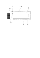
- FIG. 1 is an exploded perspective view of a speaker device showing a first embodiment of the speaker device according to the present invention.
- FIG. 2 is a longitudinal sectional view of the speaker device.
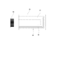
- FIG. 3 is a plan view of the diaphragm.
- FIG. 4 is an enlarged view of a part of the diaphragm in the one-dot chain line frame portion of FIG. 3.
- FIG. 5 is a block diagram of the drive circuit.
- FIG. 6 is an enlarged view of a part of a diaphragm showing a second embodiment of the speaker device according to the present invention.
- FIG. 7 is an enlarged view of a part of a diaphragm showing a third embodiment of the speaker device according to the present invention.
- FIG. 1 is an exploded perspective view of a speaker device showing a first embodiment of the speaker device according to the present invention.
- FIG. 2 is a longitudinal sectional view of the speaker device.
- FIG. 3 is a plan view of the diaphragm
- FIG. 8 is an enlarged view of a part of a diaphragm showing a fourth embodiment of the speaker device according to the present invention.
- FIG. 9 is an enlarged view of a part of a diaphragm showing a fifth embodiment of the speaker device according to the present invention.
- FIG. 1 is an exploded perspective view of the speaker device
- FIG. 2 is a longitudinal sectional view of the speaker device
- FIG. 3 is a plan view of the diaphragm
- FIG. 4 is an enlarged view of a part of the diaphragm in the one-dot chain line frame portion of FIG.
- the speaker device is an example of a full digital speaker device using a planar diaphragm.
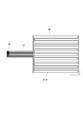
- the speaker device 10 includes a diaphragm 11, a pair of magnets 13 and 13 that sandwich the diaphragm 11 from above and below via cushioning members 12 and 12, and a pair of these members covering the whole from above and below. Holding members 14, 14.
- the diaphragm 11 is composed of a thin film-like flexible wiring board 20, and a voice voice coil pattern 21 to which a drive current is supplied based on a voice signal is formed on one surface of the flexible wiring board 20. ing. As shown in FIGS. 3 and 4, the voice voice coil pattern 21 is formed so that a plurality of conductive wire patterns meander over the entire area of the flexible wiring board 20.
- the flexible wiring board 20 has one noise canceling voice coil pattern 22 on one side of the voice voice coil pattern 21, and the voice voice coil pattern 21. And meandering so as to be substantially parallel to the line. 4 and 6 to 9, for convenience of explanation, the voice voice coil pattern 21 is indicated by a solid line, and the noise canceling voice coil pattern 22 is indicated by a one-dot chain line.
- a lead wire drawing portion 23 is provided integrally with the voice voice coil pattern 21 and the noise canceling voice coil pattern 22.
- the lead wire drawing portion 23 is provided at the tip of the lead wire drawing portion 23.
- terminal portions 24 respectively connected to the end portions of the voice voice coil pattern 21 and the noise canceling voice coil pattern 22.
- a drive current is supplied from the terminal unit 24 based on a predetermined digital audio signal and an analog noise cancellation signal.
- the magnets 13 are formed in parallel stripes so that the N poles and the S poles are alternately positioned along the line on which the voice coil pattern is formed.
- the magnetic field component perpendicular to the surface of the magnet 13 is the largest in the vicinity of the N pole and the S pole, and the smallest in the vicinity of the boundary between the N pole and the S pole.
- the horizontal magnetic field component parallel to the surface of the magnet 13 is the smallest in the vicinity of the N pole and the S pole, and the largest in the vicinity of the boundary between the N pole and the S pole. Therefore, the magnetic field component that contributes to vibrating the diaphragm 11 in the thickness direction is not a vertical component but a horizontal component (Fleming's left-hand rule).
- the voice voice coil within the plane of the diaphragm 11 is provided by arranging the linear portions of the voice voice coil pattern 21 and the noise canceling voice coil pattern 22 at positions corresponding to the vicinity of the boundary between the N pole and the S pole. Magnetic lines of force pass through the pattern 21 and the noise canceling voice coil pattern 22 so as to cross the straight line portion. Therefore, in this embodiment, the voice voice coil pattern 21 and the noise canceling voice coil pattern 22 are arranged at the boundary between the N pole and the S pole.
- a driving current is applied to the voice voice coil pattern 21 and the noise canceling voice coil pattern 22
- an electromagnetic force is generated most efficiently due to the interaction between the current and the magnetic field, and the diaphragm 11 moves in the thickness direction. It is configured to vibrate.
- the magnet 13 is formed with a plurality of through holes 25 through which sound output from the diaphragm 11 is passed.
- the voice voice coil pattern 21 and the noise canceling voice coil pattern 22 are arranged at the boundary portion between the N pole and the S pole, and the diaphragm 11 is vibrated efficiently at the boundary portion. Therefore, the through hole 25 is preferably formed at a position corresponding to a boundary portion between the N pole and the S pole.
- the buffer member 12 is made of a soft material and has a function of passing sound, and is made of, for example, a nonwoven fabric.
- the buffer member 12 is formed to have substantially the same size as the diaphragm 11, and the buffer member 12 is configured so that a predetermined gap is formed between the diaphragm 11 and the magnet 13. Yes.
- the buffer member 12 prevents the diaphragm 11 from colliding with the magnet 13 and generating an abnormal noise when the diaphragm 11 is driven.
- the buffer member 12 may include a plurality of buffer members 12 depending on its thickness and material. It can also be used in layers.
- the holding member 14 is made of, for example, a hard material such as metal, and is illustrated on the outer periphery of the holding member 14 with the diaphragm 11, the buffer member 12, and the magnet 13 sandwiched between the holding members 14.
- the diaphragm 11 is fixed so as to be held between the pair of magnets 13 with a predetermined gap by screwing screws that are not to be engaged.
- the holding member 14 is formed with a through hole 26 at the same position as the through hole 25 of the magnet 13, and the through hole 26 can efficiently radiate sound from the diaphragm 11 to the outside. It is configured to be able to.
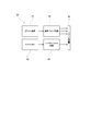
- the drive circuit 30 includes an audio driver circuit 32 to which a digital audio signal from a predetermined digital sound source 31 is input.
- the audio driver circuit 32 converts the digital audio signal into a predetermined audio drive signal.
- the driving current based on the voice driving signal is supplied to the voice voice coil pattern 21 via the terminal unit 24.
- the drive circuit 30 includes a microphone 33 that inputs external noise, and the drive circuit 30 includes a noise cancellation circuit 34 that inputs an external noise signal from the microphone 33.
- the noise cancellation circuit 34 inverts the phase of the noise signal from the microphone 33, uses the inverted signal as a noise cancellation signal, and a drive current based on the noise cancellation signal is connected to the noise cancellation voice coil pattern via the terminal unit 24. 22 is configured to be supplied.
- an audio signal sent from a predetermined digital sound source 31 is used as an audio drive signal by the audio driver circuit 32, and a drive current based on this audio drive signal is supplied to the audio voice coil pattern 21.
- external noise is input by the microphone 33 and sent to the noise cancellation circuit 34.
- the noise cancellation circuit 34 inverts the phase of the noise signal from the microphone 33, and noise cancels the drive current based on the phase-inverted noise cancellation signal.
- the voice coil pattern 22 is supplied.
- the voice coil pattern 21 and the noise canceling voice coil pattern 22 are formed on the flexible wiring board 20, and the driving current based on the noise canceling signal together with the driving current based on the sound signal. Therefore, the diaphragm 11 is vibrated on the basis of a signal obtained by synthesizing these sound signal and noise cancel signal, and the sound by the sound signal is reduced in a state where external noise is canceled. It can be output. As a result, the audio signal is not affected by the noise signal, and a reproduced sound with good sound quality can be obtained.
- the noise canceling voice coil pattern 22 is formed on the flexible wiring board 20 in addition to the voice voice coil pattern 21, only the amount of the noise canceling voice coil pattern 22 increased. The surface of the diaphragm 11 can be hardened. Therefore, the transmission speed by the diaphragm 11 can be increased, and deterioration of the high frequency characteristics can be avoided.
- FIG. 6 shows a second embodiment of the present invention.
- the noise canceling voice coil pattern 22 is formed on both sides of the voice voice coil pattern 21 formed on the flexible wiring board 20.
- the noise canceling voice coil pattern 22 is formed on one side of the voice voice coil pattern 21, but the noise canceling is performed on one side of the voice voice coil pattern 21.
- the voice coil pattern 22 is formed, the amplitude of the diaphragm 11 may be nonuniform. Therefore, in the present embodiment, the noise canceling voice coil pattern 22 is formed on both sides of the voice voice coil pattern 21 so that the diaphragm 11 can be caused to vibrate uniformly with respect to the voice voice coil pattern 21. Is.
- the voice voice coil pattern 21 and the noise canceling voice coil pattern 22 are formed on the flexible wiring board 20, and the noise canceling signal is generated together with the driving current based on the sound signal. Therefore, the diaphragm 11 is vibrated based on a signal obtained by synthesizing the sound signal and the noise cancellation signal, and the sound signal is canceled in a state in which the external noise is canceled. Can output sound. Further, since the noise canceling voice coil pattern 22 is formed on both sides of the voice voice coil pattern 21 on the flexible wiring board 20, the surface of the diaphragm 11 is made harder than in the first embodiment. Therefore, the transmission speed by the diaphragm 11 can be increased, and the deterioration of the high frequency characteristics can be avoided.
- FIG. 7 shows a third embodiment of the present invention.
- a speaker device using the planar diaphragm 11 tends to have lower impedance and higher current consumption than a dynamic speaker device.
- the noise canceling voice coil pattern 22 is formed on both sides of the voice voice coil pattern 21 as in the second embodiment, and the end portions of the noise canceling voice coil patterns 22 are formed. By electrically connecting, one long noise canceling voice coil pattern 22 disposed on both sides of the voice voice coil pattern 21 is formed.
- the length of the noise canceling voice coil pattern 22 is formed to be long, so that the resistance value of the noise canceling voice coil pattern 22 is increased, so that the impedance of the noise canceling voice coil pattern 22 can be increased. It becomes.
- the voice coil pattern 21 and the noise canceling voice coil pattern 22 are formed on the flexible wiring board 20, and the drive currents based on the sound signal and the noise canceling signal are respectively supplied. Therefore, the diaphragm 11 is vibrated based on a signal obtained by synthesizing the audio signal and the noise cancellation signal, and the audio signal is output in a state where external noise is canceled. It is something that can be done. Further, since the voice voice coil pattern 21 and the noise canceling voice coil pattern 22 are formed on the flexible wiring board 20, the surface of the diaphragm 11 can be hardened, and the transmission speed of the diaphragm 11 can be increased. It can be increased, and deterioration of the high frequency characteristics can be avoided.
- the end portion of the noise canceling voice coil pattern 22 is electrically connected so that the length of the noise canceling voice coil pattern 22 is increased, the resistance value of the noise canceling voice coil pattern 22 is increased. Therefore, the impedance of the noise canceling voice coil pattern 22 can be increased, and as a result, the current consumption can be reduced, thereby preventing the overcurrent protection circuit from functioning. it can.
- the wiring pattern of the noise canceling voice coil pattern 22 By devising the wiring pattern of the noise canceling voice coil pattern 22, it is possible to ensure a long length of the noise canceling voice coil pattern 22.
- the impedance of the noise canceling voice coil pattern 22 can be increased.
- the impedance of the noise canceling voice coil pattern 22 can be easily increased without devising such a wiring pattern. It can be increased.
- FIG. 8 shows a fourth embodiment of the present invention.
- the noise canceling voice coil pattern 22 is formed on both sides of the voice voice coil pattern 21, and each of these noise canceling voice coil patterns 22 is also formed.
- the resistance element 35 is connected to the middle part.
- the voice coil pattern 21 and the noise canceling voice coil pattern 22 are formed on the flexible wiring board 20, and the drive currents based on the sound signal and the noise canceling signal are respectively supplied. Therefore, the diaphragm 11 is vibrated based on a signal obtained by synthesizing the audio signal and the noise cancellation signal, and the audio signal is output in a state where external noise is canceled. It is something that can be done. Further, since the voice voice coil pattern 21 and the noise canceling voice coil pattern 22 are formed on the flexible wiring board 20, the surface of the diaphragm 11 can be hardened, and the transmission speed of the diaphragm 11 can be increased. It can be increased, and deterioration of the high frequency characteristics can be avoided.
- the resistance element 35 Since the resistance element 35 is connected to the middle part of the noise canceling voice coil pattern 22, the resistance value of the noise canceling voice coil pattern 22 can be increased by the resistance element 35.
- the impedance of the voice coil pattern 22 can be increased, and as a result, the current consumption can be reduced, thereby preventing the overcurrent protection circuit from functioning.
- FIG. 9 shows a fifth embodiment of the present invention.
- a reinforcing pattern 36 is formed between the voice voice coil pattern 21 and the noise canceling voice coil pattern 22 of the flexible wiring board 20.
- the reinforcing pattern 36 is configured by a pattern made of, for example, a metal foil such as a copper foil or a foil of hard material.
- the voice voice coil pattern 21 and the noise canceling voice coil pattern 22 are formed on the flexible wiring board 20 in the same manner as in each of the above embodiments, the voice can be output in a state where external noise is canceled. Audio by signals can be output. Further, the voice coil pattern 21 and the noise canceling voice coil pattern 22 are formed on the flexible wiring board 20, and the reinforcing pattern 36 is formed between the voice voice coil pattern 21 and the noise canceling voice coil pattern 22. Therefore, the surface of the diaphragm 11 can be made harder, the transmission speed by the diaphragm 11 can be increased, and the high frequency characteristics can be remarkably improved.
- each said embodiment shows the one aspect
- This invention is not limited to the said embodiment.
- the case where one or two noise canceling voice coil patterns 22 are formed has been described.
- three or more noise canceling voice coil patterns 22 may be formed.
- the voice voice coil pattern 21 and the noise canceling voice coil pattern 22 are formed on one surface side of the flexible wiring board 20. For example, they are formed on both surfaces of the flexible wiring board 20. You may make it do.
- a voice coil pattern for voice 21 is formed on the flexible wiring board 20 and an insulating layer is formed so as to cover the voice coil pattern 21 for voice, whereby a voice coil for noise cancellation is formed on the surface of the insulating layer.
- the pattern 22 may be formed.
- the voice voice coil pattern 21 and the noise canceling voice coil pattern 22 can be formed to overlap each other.
- the N pole and the S pole are formed in parallel stripes on the magnet 13 and the voice voice coil pattern 21 and the noise canceling voice coil pattern 22 are arranged to meander.
- the voice voice coil pattern 21 and the noise canceling voice coil pattern 22 are arranged according to the magnetized state of the magnet 13 by changing the magnetized state of the N pole and the S pole of the magnet 13. It is something that can be done.
Abstract
The present invention provides a speaker device in which time lag between an acoustic signal and a noise cancelation signal is prevented, degradation in high-frequency characteristics is avoided, and acoustic characteristics can be improved. A flat diaphragm 11 is provided with a flexible wiring board 20, there being formed on said board 20: an acoustic voice coil pattern 21, which is formed correspondingly with respect to the magnetic field formed by a magnet 13, and to which a drive current based on an acoustic signal is supplied; and a noise-cancelation voice coil pattern 22, to which a drive current based on a noise cancelation signal is supplied.
Description
本発明は、スピーカ装置に関する。
The present invention relates to a speaker device.
従来から、スピーカ装置やヘッドホンなどにおいて、外部の騒音を打ち消し、使用者の耳には楽音のみが聞こえるようにしたノイズキャンセル技術が普及している。このノイズキャンセル技術は、外部の騒音をマイクロホンで検知し、検知した騒音信号と逆位相のノイズキャンセル信号を発生させ、このノイズキャンセル信号をスピーカ装置などから出力させることにより、騒音を打ち消すものである。
Conventionally, in a speaker device or a headphone, a noise canceling technique that cancels external noise so that only a musical sound can be heard by a user's ear has been widespread. This noise cancellation technology detects external noise with a microphone, generates a noise cancellation signal having a phase opposite to the detected noise signal, and outputs the noise cancellation signal from a speaker device or the like, thereby canceling the noise. .
一方、近年、スピーカにデジタル信号を直接的に入力することができるフルデジタルスピーカ装置が開発されている。このフルデジタルスピーカ装置は、スピーカにダイレクトにデジタル信号を伝送することが可能であるため、デジタル/アナログ変換が不要とな、デジタル/アナログ変換器の性能に左右されることなく高音質を実現することができるものである。
しかし、このフルデジタルスピーカ装置に、前述のノイズキャンセル技術を適用すると、内部のデジタルフィルタ部の演算回路による遅延が原因で、騒音信号が入力されてから、音声が出力されるまでに0.5msec~3msecほどの遅れが発生する。
そのため、通常のノイズキャンセル技術のように、入力した騒音信号に対して信号処理を行って、ノイズの除去を行おうとすると、信号処理を行う分の遅延がノイズ処理信号にも発生し、実ノイズに対して遅れが生じるために 有効なノイズ低減を行うことができなくなるという問題があった。 On the other hand, in recent years, a full digital speaker device capable of directly inputting a digital signal to a speaker has been developed. Since this full digital speaker device can transmit digital signals directly to the speaker, digital / analog conversion is unnecessary, and high sound quality is achieved without being affected by the performance of the digital / analog converter. It is something that can be done.
However, if the above-described noise cancellation technique is applied to this full digital speaker device, it takes 0.5 msec from the input of the noise signal to the output of sound due to the delay caused by the arithmetic circuit of the internal digital filter section. A delay of about 3 msec occurs.
For this reason, if signal processing is performed on the input noise signal and noise is removed as in normal noise cancellation technology, a delay corresponding to the amount of signal processing also occurs in the noise processing signal. However, there is a problem that effective noise reduction cannot be performed due to the delay.
このような遅延を防止するため、従来、例えば、1つの振動板と振動板を駆動する二つのボイスコイルを備えたスピーカユニットを備え、一方のボイスコイルには楽音信号を、他方のボイスコイルには騒音検出用マイクロホンで検出された騒音信号に基づくノイズキャンセル信号を入力するようにしたものがある(特許文献1を参照。)。
In order to prevent such a delay, conventionally, for example, a speaker unit including one diaphragm and two voice coils for driving the diaphragm is provided, and a musical tone signal is transmitted to one voice coil and the other voice coil is coupled to the other voice coil. There is a type in which a noise cancellation signal based on a noise signal detected by a noise detection microphone is input (see Patent Document 1).
前記特許文献1においては、2つのコイルを巻いたボイスコイルの一方にノイズキャンセル信号を入力することで、1枚の振動板を駆動してノイズをキャンセルするものであるため、ノイズキャンセル用の信号を単純化することができ、実ノイズに対する遅延を極力少なくすることができるものである。
しかしながら、前記特許文献1のものは、通常のダイナミック型のスピーカに適用されるものであり、ボイスコイルを増やすことでスピーカ装置のダイヤフラム、ボイスコイル部の自重が増すので、振動板の振動を抑制してしまい、高域特性を妨げ、音響特性の低下を招いてしまうという問題を有している。
本発明は、前記した点に鑑みてなされたものであり、音声信号とノイズキャンセル信号との時間のずれを防止するとともに、高域特性の悪化を回避して音響特性の向上を図ることのできるスピーカ装置を提供することを目的とするものである。 In Patent Document 1, since a noise cancel signal is input to one of two voice coils wound with two coils to drive one diaphragm and cancel the noise, a noise cancel signal is used. The delay with respect to actual noise can be reduced as much as possible.
However, the thing of the said patent document 1 is applied to a normal dynamic type speaker, and the diaphragm of a speaker apparatus and the dead weight of a voice coil part increase by increasing a voice coil, Therefore The vibration of a diaphragm is suppressed. Therefore, there is a problem that the high frequency characteristics are hindered and the acoustic characteristics are deteriorated.
The present invention has been made in view of the above points, and can prevent time lag between an audio signal and a noise cancellation signal, and can improve acoustic characteristics by avoiding deterioration of high frequency characteristics. An object of the present invention is to provide a speaker device.
前記目的を達成するため、本発明は、平面振動板を備えたスピーカ装置において、前記平面振動板は、マグネットの形成磁界に対応して形成され、音声信号に基づく駆動電流が供給される音声用ボイスコイルパターンを備えるとともに、ノイズキャンセル信号に基づく駆動電流が供給されるノイズキャンセル用ボイスコイルパターンを備えていることを特徴とする。
In order to achieve the above object, the present invention provides a speaker device including a flat diaphragm, wherein the flat diaphragm is formed corresponding to a magnetic field formed by a magnet and supplied with a driving current based on an audio signal. A voice coil pattern is provided, and a noise canceling voice coil pattern to which a drive current based on a noise cancellation signal is supplied is provided.
また、前記構成において、前記平面振動板は、フレキシブル配線基板に前記音声用ボイスコイルパターンおよび前記ノイズキャンセル用ボイスコイルパターンを形成した構成としてもよい。さらに、前記構成において、前記ノイズキャンセル用ボイスコイルパターンは、前記音声用ボイスコイルパターンの一側に形成されている構成としてもよい。また、前記構成において、前記ノイズキャンセル用ボイスコイルパターンは、前記音声用ボイスコイルパターンの両側に形成されている構成としてもよい。
In the above-described configuration, the planar diaphragm may have a configuration in which the voice voice coil pattern and the noise canceling voice coil pattern are formed on a flexible wiring board. Further, in the above configuration, the noise canceling voice coil pattern may be formed on one side of the voice voice coil pattern. Moreover, the said structure WHEREIN: The said noise cancellation voice coil pattern is good also as a structure currently formed in the both sides of the said voice voice coil pattern.
また、前記構成において、前記ノイズキャンセル用ボイスコイルパターンは、複数本形成され、前記各ノイズキャンセル用ボイスコイルパターンの端部を電気的に接続して1本のノイズキャンセル用ボイスコイルパターンとした構成としてもよい。さらに、前記構成において、前記ノイズキャンセル用ボイスコイルパターンの中途部に抵抗素子を接続した構成としてもよい。また、前記構成において、前記平面振動板の前記音声用ボイスコイルパターンまたは前記ノイズキャンセル用ボイスコイルパターンの間に、補強パターンを形成した構成としてもよい。
Further, in the above configuration, a plurality of the noise canceling voice coil patterns are formed, and one end of each noise canceling voice coil pattern is electrically connected to form one noise canceling voice coil pattern. It is good. Furthermore, the said structure WHEREIN: It is good also as a structure which connected the resistive element to the middle part of the said voice coil pattern for noise cancellation. Further, in the above configuration, a reinforcing pattern may be formed between the voice voice coil pattern or the noise canceling voice coil pattern of the planar diaphragm.
本発明によれば、音声信号に基づく駆動電流が供給される音声用ボイスコイルパターンと、ノイズキャンセル信号に基づく駆動電流が供給されるノイズキャンセル用ボイスコイルパターンとを形成するようにしているので、音声信号が騒音信号の影響を受けることがなく、音質が良好な再生音を得ることができる。また、音声用ボイスコイルパターンおよびノイズキャンセル用ボイスコイルパターンを形成するようにしているので、振動板の表面を硬くすることが可能となる。そのため、振動板による伝達速度を増加させることができ、高域特性の悪化を回避することができる。
According to the present invention, the voice voice coil pattern to which the driving current based on the audio signal is supplied and the noise canceling voice coil pattern to which the driving current based on the noise cancellation signal is supplied are formed. The audio signal is not affected by the noise signal, and a reproduced sound with good sound quality can be obtained. Moreover, since the voice voice coil pattern and the noise canceling voice coil pattern are formed, the surface of the diaphragm can be hardened. Therefore, the transmission speed by the diaphragm can be increased, and deterioration of the high frequency characteristics can be avoided.
以下、本発明に係るスピーカ装置の実施形態について図面を参照して説明する。
図1は、スピーカ装置の分解斜視図であり、図2は、スピーカ装置の縦断面図である。図3は、振動板の平面図であり、図4は、図3の一点鎖線枠部分における振動板の一部の拡大図である。
本実施形態においては、スピーカ装置は、平面振動板を用いたフルデジタルスピーカ装置の例を示している。 Hereinafter, embodiments of a speaker device according to the present invention will be described with reference to the drawings.
FIG. 1 is an exploded perspective view of the speaker device, and FIG. 2 is a longitudinal sectional view of the speaker device. FIG. 3 is a plan view of the diaphragm, and FIG. 4 is an enlarged view of a part of the diaphragm in the one-dot chain line frame portion of FIG.
In the present embodiment, the speaker device is an example of a full digital speaker device using a planar diaphragm.
本実施形態におけるスピーカ装置10は、振動板11と、この振動板11を緩衝部材12,12を介して上下から挟み込む一対のマグネット13,13と、これらの部材の全体を上下から被覆する一対の保持部材14,14とを備えている。
振動板11は、薄肉フィルム状のフレキシブル配線基板20から構成されるものであり、フレキシブル配線基板20の一面には、音声信号に基づいて駆動電流が供給される音声用ボイスコイルパターン21が形成されている。この音声用ボイスコイルパターン21は、図3および図4に示すように、複数本の導線パターンをフレキシブル配線基板20の全域にわたって蛇行するように形成するものである。 Thespeaker device 10 according to the present embodiment includes a diaphragm 11, a pair of magnets 13 and 13 that sandwich the diaphragm 11 from above and below via cushioning members 12 and 12, and a pair of these members covering the whole from above and below. Holding members 14, 14.
Thediaphragm 11 is composed of a thin film-like flexible wiring board 20, and a voice voice coil pattern 21 to which a drive current is supplied based on a voice signal is formed on one surface of the flexible wiring board 20. ing. As shown in FIGS. 3 and 4, the voice voice coil pattern 21 is formed so that a plurality of conductive wire patterns meander over the entire area of the flexible wiring board 20.
振動板11は、薄肉フィルム状のフレキシブル配線基板20から構成されるものであり、フレキシブル配線基板20の一面には、音声信号に基づいて駆動電流が供給される音声用ボイスコイルパターン21が形成されている。この音声用ボイスコイルパターン21は、図3および図4に示すように、複数本の導線パターンをフレキシブル配線基板20の全域にわたって蛇行するように形成するものである。 The
The
また、本実施形態においては、フレキシブル配線基板20には、図3に示すように、音声用ボイスコイルパターン21の一側に、1本のノイズキャンセル用ボイスコイルパターン22が音声用ボイスコイルパターン21とほぼ平行となるように蛇行して形成されている。
なお、図4、図6から図9においては、説明の都合上、音声用ボイスコイルパターン21を実線で示すとともに、ノイズキャンセル用ボイスコイルパターン22を一点鎖線で示す。 In the present embodiment, as shown in FIG. 3, theflexible wiring board 20 has one noise canceling voice coil pattern 22 on one side of the voice voice coil pattern 21, and the voice voice coil pattern 21. And meandering so as to be substantially parallel to the line.
4 and 6 to 9, for convenience of explanation, the voicevoice coil pattern 21 is indicated by a solid line, and the noise canceling voice coil pattern 22 is indicated by a one-dot chain line.
なお、図4、図6から図9においては、説明の都合上、音声用ボイスコイルパターン21を実線で示すとともに、ノイズキャンセル用ボイスコイルパターン22を一点鎖線で示す。 In the present embodiment, as shown in FIG. 3, the
4 and 6 to 9, for convenience of explanation, the voice
また、振動板11の一側には、音声用ボイスコイルパターン21およびノイズキャンセル用ボイスコイルパターン22を外部に引き出す導線引き出し部23が一体に設けられており、この導線引き出し部23の先端部には、音声用ボイスコイルパターン21およびノイズキャンセル用ボイスコイルパターン22の端部にそれぞれ接続される端子部24が形成されている。
そして、この端子部24から所定のデジタルの音声信号およびアナログのノイズキャンセル信号に基づいて駆動電流を通電するように構成されている。 In addition, on one side of thediaphragm 11, a lead wire drawing portion 23 is provided integrally with the voice voice coil pattern 21 and the noise canceling voice coil pattern 22. The lead wire drawing portion 23 is provided at the tip of the lead wire drawing portion 23. Are formed with terminal portions 24 respectively connected to the end portions of the voice voice coil pattern 21 and the noise canceling voice coil pattern 22.
A drive current is supplied from theterminal unit 24 based on a predetermined digital audio signal and an analog noise cancellation signal.
そして、この端子部24から所定のデジタルの音声信号およびアナログのノイズキャンセル信号に基づいて駆動電流を通電するように構成されている。 In addition, on one side of the
A drive current is supplied from the
また、図2に示すように、マグネット13は、ボイスコイルパターンの形成されたラインに沿ってN極とS極とが交互に位置するように平行縞状に形成されている。
ここで、マグネット13の表面に垂直な磁界成分は、N極およびS極の付近で最も大きく、N極とS極の境界付近では最も小さくなる。これに対して、マグネット13の表面に平行な水平の磁界成分は、N極およびS極の付近では最も小さく、N極とS極の境界付近では最も大きい。そのため、振動板11を厚み方向に振動させるのに寄与する磁界成分は、垂直成分ではなく水平成分である(フレミングの左手の法則)。 As shown in FIG. 2, themagnets 13 are formed in parallel stripes so that the N poles and the S poles are alternately positioned along the line on which the voice coil pattern is formed.
Here, the magnetic field component perpendicular to the surface of themagnet 13 is the largest in the vicinity of the N pole and the S pole, and the smallest in the vicinity of the boundary between the N pole and the S pole. On the other hand, the horizontal magnetic field component parallel to the surface of the magnet 13 is the smallest in the vicinity of the N pole and the S pole, and the largest in the vicinity of the boundary between the N pole and the S pole. Therefore, the magnetic field component that contributes to vibrating the diaphragm 11 in the thickness direction is not a vertical component but a horizontal component (Fleming's left-hand rule).
ここで、マグネット13の表面に垂直な磁界成分は、N極およびS極の付近で最も大きく、N極とS極の境界付近では最も小さくなる。これに対して、マグネット13の表面に平行な水平の磁界成分は、N極およびS極の付近では最も小さく、N極とS極の境界付近では最も大きい。そのため、振動板11を厚み方向に振動させるのに寄与する磁界成分は、垂直成分ではなく水平成分である(フレミングの左手の法則)。 As shown in FIG. 2, the
Here, the magnetic field component perpendicular to the surface of the
そのため、N極とS極の境界付近に対応する位置に、音声用ボイスコイルパターン21およびノイズキャンセル用ボイスコイルパターン22の直線部分を配置することにより、振動板11の面内で音声用ボイスコイルパターン21およびノイズキャンセル用ボイスコイルパターン22の直線部分を横切るような向きに磁力線が通ることになる。
したがって、本実施形態においては、N極とS極との境界部分に、音声用ボイスコイルパターン21とノイズキャンセル用ボイスコイルパターン22とを配置するように構成されている。そして、音声用ボイスコイルパターン21およびノイズキャンセル用ボイスコイルパターン22に駆動電流を通電することにより、その電流と磁界との相互作用により最も効率よく電磁力が発生し、振動板11が厚み方向に振動するように構成されている。 Therefore, the voice voice coil within the plane of thediaphragm 11 is provided by arranging the linear portions of the voice voice coil pattern 21 and the noise canceling voice coil pattern 22 at positions corresponding to the vicinity of the boundary between the N pole and the S pole. Magnetic lines of force pass through the pattern 21 and the noise canceling voice coil pattern 22 so as to cross the straight line portion.
Therefore, in this embodiment, the voicevoice coil pattern 21 and the noise canceling voice coil pattern 22 are arranged at the boundary between the N pole and the S pole. When a driving current is applied to the voice voice coil pattern 21 and the noise canceling voice coil pattern 22, an electromagnetic force is generated most efficiently due to the interaction between the current and the magnetic field, and the diaphragm 11 moves in the thickness direction. It is configured to vibrate.
したがって、本実施形態においては、N極とS極との境界部分に、音声用ボイスコイルパターン21とノイズキャンセル用ボイスコイルパターン22とを配置するように構成されている。そして、音声用ボイスコイルパターン21およびノイズキャンセル用ボイスコイルパターン22に駆動電流を通電することにより、その電流と磁界との相互作用により最も効率よく電磁力が発生し、振動板11が厚み方向に振動するように構成されている。 Therefore, the voice voice coil within the plane of the
Therefore, in this embodiment, the voice
また、図1に示すように、マグネット13には、振動板11から出力される音声を通すための複数の貫通孔25が形成されている。前述のように、N極とS極との境界部分に音声用ボイスコイルパターン21とノイズキャンセル用ボイスコイルパターン22とを配置して、この境界部分で、振動板11を効率よく振動させるようにしていることから、貫通孔25は、N極とS極との境界部分に対応する位置に形成することが好ましい。
Further, as shown in FIG. 1, the magnet 13 is formed with a plurality of through holes 25 through which sound output from the diaphragm 11 is passed. As described above, the voice voice coil pattern 21 and the noise canceling voice coil pattern 22 are arranged at the boundary portion between the N pole and the S pole, and the diaphragm 11 is vibrated efficiently at the boundary portion. Therefore, the through hole 25 is preferably formed at a position corresponding to a boundary portion between the N pole and the S pole.
また、緩衝部材12は、軟質材料からなり、かつ、音声を通す機能を有するものであり、例えば、不織布などにより構成されるものである。緩衝部材12は、振動板11とほぼ同様の大きさに形成されるものであり、この緩衝部材12により、振動板11とマグネット13との間に所定の間隙が形成されるように構成されている。この緩衝部材12は、振動板11の駆動時に振動板11がマグネット13に衝突して異音を発することを防止するものであり、緩衝部材12は、その厚さや材質により、必要に応じて複数枚重ねて使用することもできる。
Further, the buffer member 12 is made of a soft material and has a function of passing sound, and is made of, for example, a nonwoven fabric. The buffer member 12 is formed to have substantially the same size as the diaphragm 11, and the buffer member 12 is configured so that a predetermined gap is formed between the diaphragm 11 and the magnet 13. Yes. The buffer member 12 prevents the diaphragm 11 from colliding with the magnet 13 and generating an abnormal noise when the diaphragm 11 is driven. The buffer member 12 may include a plurality of buffer members 12 depending on its thickness and material. It can also be used in layers.
保持部材14は、例えば、金属などの硬質材料により構成されており、各保持部材14の間に、振動板11、緩衝部材12およびマグネット13を挟持した状態で、保持部材14の外周辺に図示しないねじなどを螺合させることにより、一対のマグネット13の間に振動板11が所定間隙をもって保持されるように固定するように構成されている。また、保持部材14には、マグネット13の貫通孔25と同様の位置に、貫通孔26が形成されており、この貫通孔26により、振動板11からの音声を外部に効率よく放射することができるように構成されている。
The holding member 14 is made of, for example, a hard material such as metal, and is illustrated on the outer periphery of the holding member 14 with the diaphragm 11, the buffer member 12, and the magnet 13 sandwiched between the holding members 14. The diaphragm 11 is fixed so as to be held between the pair of magnets 13 with a predetermined gap by screwing screws that are not to be engaged. Further, the holding member 14 is formed with a through hole 26 at the same position as the through hole 25 of the magnet 13, and the through hole 26 can efficiently radiate sound from the diaphragm 11 to the outside. It is configured to be able to.
次に、前述のスピーカ装置10の駆動回路について図5を参照して説明する。
図5に示すように、駆動回路30は、所定のデジタル音源31からのデジタル音声信号が入力される音声ドライバ回路32を備えており、音声ドライバ回路32は、デジタル音声信号を所定の音声駆動信号とし、この音声駆動信号に基づく駆動電流を端子部24を介して音声用ボイスコイルパターン21に供給するように構成されている。
一方、駆動回路30は、外部の騒音を入力するマイクロホン33を備えており、駆動回路30は、マイクロホン33からの外部の騒音信号を入力するノイズキャンセル回路34を備えている。ノイズキャンセル回路34は、マイクロホン33からの騒音信号の位相を反転し、この位相反転した信号をノイズキャンセル信号とし、このノイズキャンセル信号に基づく駆動電流を端子部24を介してノイズキャンセル用ボイスコイルパターン22に供給するように構成されている。 Next, the drive circuit of the above-describedspeaker device 10 will be described with reference to FIG.
As shown in FIG. 5, thedrive circuit 30 includes an audio driver circuit 32 to which a digital audio signal from a predetermined digital sound source 31 is input. The audio driver circuit 32 converts the digital audio signal into a predetermined audio drive signal. The driving current based on the voice driving signal is supplied to the voice voice coil pattern 21 via the terminal unit 24.
On the other hand, thedrive circuit 30 includes a microphone 33 that inputs external noise, and the drive circuit 30 includes a noise cancellation circuit 34 that inputs an external noise signal from the microphone 33. The noise cancellation circuit 34 inverts the phase of the noise signal from the microphone 33, uses the inverted signal as a noise cancellation signal, and a drive current based on the noise cancellation signal is connected to the noise cancellation voice coil pattern via the terminal unit 24. 22 is configured to be supplied.
図5に示すように、駆動回路30は、所定のデジタル音源31からのデジタル音声信号が入力される音声ドライバ回路32を備えており、音声ドライバ回路32は、デジタル音声信号を所定の音声駆動信号とし、この音声駆動信号に基づく駆動電流を端子部24を介して音声用ボイスコイルパターン21に供給するように構成されている。
一方、駆動回路30は、外部の騒音を入力するマイクロホン33を備えており、駆動回路30は、マイクロホン33からの外部の騒音信号を入力するノイズキャンセル回路34を備えている。ノイズキャンセル回路34は、マイクロホン33からの騒音信号の位相を反転し、この位相反転した信号をノイズキャンセル信号とし、このノイズキャンセル信号に基づく駆動電流を端子部24を介してノイズキャンセル用ボイスコイルパターン22に供給するように構成されている。 Next, the drive circuit of the above-described
As shown in FIG. 5, the
On the other hand, the
次に、本実施形態の作用について説明する。
本実施形態においては、所定のデジタル音源31から送られる音声信号を音声ドライバ回路32により音声駆動信号とし、この音声駆動信号に基づく駆動電流を音声用ボイスコイルパターン21に供給する。
一方、マイクロホン33により外部の騒音を入力してノイズキャンセル回路34に送り、ノイズキャンセル回路34により、マイクロホン33からの騒音信号の位相を反転し、位相反転したノイズキャンセル信号に基づく駆動電流をノイズキャンセル用ボイスコイルパターン22に供給する。 Next, the operation of this embodiment will be described.
In the present embodiment, an audio signal sent from a predetermined digitalsound source 31 is used as an audio drive signal by the audio driver circuit 32, and a drive current based on this audio drive signal is supplied to the audio voice coil pattern 21.
On the other hand, external noise is input by themicrophone 33 and sent to the noise cancellation circuit 34. The noise cancellation circuit 34 inverts the phase of the noise signal from the microphone 33, and noise cancels the drive current based on the phase-inverted noise cancellation signal. The voice coil pattern 22 is supplied.
本実施形態においては、所定のデジタル音源31から送られる音声信号を音声ドライバ回路32により音声駆動信号とし、この音声駆動信号に基づく駆動電流を音声用ボイスコイルパターン21に供給する。
一方、マイクロホン33により外部の騒音を入力してノイズキャンセル回路34に送り、ノイズキャンセル回路34により、マイクロホン33からの騒音信号の位相を反転し、位相反転したノイズキャンセル信号に基づく駆動電流をノイズキャンセル用ボイスコイルパターン22に供給する。 Next, the operation of this embodiment will be described.
In the present embodiment, an audio signal sent from a predetermined digital
On the other hand, external noise is input by the
そして、音声信号に基づく駆動電流およびノイズキャンセル信号に基づく駆動電流が供給されることにより、これら各電流とマグネット13の磁界との相互作用により、電磁力が発生して、振動板11が厚さ方向に振動するものである。このとき、音声信号に基づく駆動電流とともに、ノイズキャンセル信号に基づく駆動電流を供給するようにしているので、これら音声信号とノイズキャンセル信号とが合成された信号に基づいて振動板11が振動されることになる。そのため、外部の騒音を打ち消した状態で、音声信号による音声を出力することができるものである。
Then, by supplying a driving current based on the audio signal and a driving current based on the noise cancellation signal, an electromagnetic force is generated due to the interaction between each of these currents and the magnetic field of the magnet 13, and the diaphragm 11 has a thickness. It vibrates in the direction. At this time, since the drive current based on the noise cancellation signal is supplied together with the drive current based on the audio signal, the diaphragm 11 is vibrated based on a signal obtained by synthesizing the audio signal and the noise cancellation signal. It will be. For this reason, it is possible to output a voice by a voice signal in a state where external noise is canceled.
以上述べたように、本実施形態においては、フレキシブル配線基板20に音声用ボイスコイルパターン21およびノイズキャンセル用ボイスコイルパターン22を形成し、音声信号に基づく駆動電流とともに、ノイズキャンセル信号に基づく駆動電流を供給するようにしているので、これら音声信号とノイズキャンセル信号とが合成された信号に基づいて振動板11が振動されることになり、外部の騒音を打ち消した状態で、音声信号による音声を出力することができるものである。その結果、音声信号が騒音信号の影響を受けることがなく、音質が良好な再生音を得ることができる。
また、本実施形態においては、フレキシブル配線基板20に音声用ボイスコイルパターン21の他にノイズキャンセル用ボイスコイルパターン22を形成するようにしているので、ノイズキャンセル用ボイスコイルパターン22が増えた分だけ、振動板11の表面を硬くすることが可能となる。そのため、振動板11による伝達速度を増加させることができ、高域特性の悪化を回避することができる。 As described above, in the present embodiment, thevoice coil pattern 21 and the noise canceling voice coil pattern 22 are formed on the flexible wiring board 20, and the driving current based on the noise canceling signal together with the driving current based on the sound signal. Therefore, the diaphragm 11 is vibrated on the basis of a signal obtained by synthesizing these sound signal and noise cancel signal, and the sound by the sound signal is reduced in a state where external noise is canceled. It can be output. As a result, the audio signal is not affected by the noise signal, and a reproduced sound with good sound quality can be obtained.
In this embodiment, since the noise cancelingvoice coil pattern 22 is formed on the flexible wiring board 20 in addition to the voice voice coil pattern 21, only the amount of the noise canceling voice coil pattern 22 increased. The surface of the diaphragm 11 can be hardened. Therefore, the transmission speed by the diaphragm 11 can be increased, and deterioration of the high frequency characteristics can be avoided.
また、本実施形態においては、フレキシブル配線基板20に音声用ボイスコイルパターン21の他にノイズキャンセル用ボイスコイルパターン22を形成するようにしているので、ノイズキャンセル用ボイスコイルパターン22が増えた分だけ、振動板11の表面を硬くすることが可能となる。そのため、振動板11による伝達速度を増加させることができ、高域特性の悪化を回避することができる。 As described above, in the present embodiment, the
In this embodiment, since the noise canceling
次に、本発明の第2実施形態について説明する。
図6は、本発明の第2実施形態を示したものである。本実施形態においては、フレキシブル配線基板20に形成された音声用ボイスコイルパターン21の両側にノイズキャンセル用ボイスコイルパターン22を形成するようにしたものである。 Next, a second embodiment of the present invention will be described.
FIG. 6 shows a second embodiment of the present invention. In this embodiment, the noise cancelingvoice coil pattern 22 is formed on both sides of the voice voice coil pattern 21 formed on the flexible wiring board 20.
図6は、本発明の第2実施形態を示したものである。本実施形態においては、フレキシブル配線基板20に形成された音声用ボイスコイルパターン21の両側にノイズキャンセル用ボイスコイルパターン22を形成するようにしたものである。 Next, a second embodiment of the present invention will be described.
FIG. 6 shows a second embodiment of the present invention. In this embodiment, the noise canceling
すなわち、前記第1実施形態においては、音声用ボイスコイルパターン21の一側にノイズキャンセル用ボイスコイルパターン22を形成するようにしたものであるが、音声用ボイスコイルパターン21の一側にノイズキャンセル用ボイスコイルパターン22を形成した場合には、振動板11の振幅が不均一になってしまうおそれがある。
そのため、本実施形態においては、音声用ボイスコイルパターン21の両側にノイズキャンセル用ボイスコイルパターン22を形成することにより、音声用ボイスコイルパターン21に対して振動板11を均一に振動させることができるものである。 That is, in the first embodiment, the noise cancelingvoice coil pattern 22 is formed on one side of the voice voice coil pattern 21, but the noise canceling is performed on one side of the voice voice coil pattern 21. When the voice coil pattern 22 is formed, the amplitude of the diaphragm 11 may be nonuniform.
Therefore, in the present embodiment, the noise cancelingvoice coil pattern 22 is formed on both sides of the voice voice coil pattern 21 so that the diaphragm 11 can be caused to vibrate uniformly with respect to the voice voice coil pattern 21. Is.
そのため、本実施形態においては、音声用ボイスコイルパターン21の両側にノイズキャンセル用ボイスコイルパターン22を形成することにより、音声用ボイスコイルパターン21に対して振動板11を均一に振動させることができるものである。 That is, in the first embodiment, the noise canceling
Therefore, in the present embodiment, the noise canceling
本実施形態においても、前記第1実施形態と同様に、フレキシブル配線基板20に音声用ボイスコイルパターン21およびノイズキャンセル用ボイスコイルパターン22を形成し、音声信号に基づく駆動電流とともに、ノイズキャンセル信号に基づく駆動電流を供給するようにしているので、これら音声信号とノイズキャンセル信号とが合成された信号に基づいて振動板11が振動されることになり、外部の騒音を打ち消した状態で、音声信号による音声を出力することができるものである。
また、フレキシブル配線基板20に音声用ボイスコイルパターン21の両側にノイズキャンセル用ボイスコイルパターン22を形成するようにしているので、第1実施形態と比較して、より振動板11の表面を硬くすることが可能となり、振動板11による伝達速度を増加させることができ、高域特性の悪化を回避することができる。 Also in the present embodiment, as in the first embodiment, the voicevoice coil pattern 21 and the noise canceling voice coil pattern 22 are formed on the flexible wiring board 20, and the noise canceling signal is generated together with the driving current based on the sound signal. Therefore, the diaphragm 11 is vibrated based on a signal obtained by synthesizing the sound signal and the noise cancellation signal, and the sound signal is canceled in a state in which the external noise is canceled. Can output sound.
Further, since the noise cancelingvoice coil pattern 22 is formed on both sides of the voice voice coil pattern 21 on the flexible wiring board 20, the surface of the diaphragm 11 is made harder than in the first embodiment. Therefore, the transmission speed by the diaphragm 11 can be increased, and the deterioration of the high frequency characteristics can be avoided.
また、フレキシブル配線基板20に音声用ボイスコイルパターン21の両側にノイズキャンセル用ボイスコイルパターン22を形成するようにしているので、第1実施形態と比較して、より振動板11の表面を硬くすることが可能となり、振動板11による伝達速度を増加させることができ、高域特性の悪化を回避することができる。 Also in the present embodiment, as in the first embodiment, the voice
Further, since the noise canceling
次に、本発明の第3実施形態について説明する。
図7は、本発明の第3実施形態を示したものである。一般に、平面振動板11を用いたスピーカ装置は、ダイナミック型のスピーカ装置に比較して、インピーダンスが小さく、消費電流が大きくなる傾向にある。これにより、パワーアンプ回路の消費電力の増大や、これによる過電流保護回路が機能してしまう可能性がある。
そのため、本実施形態においては、前記第2実施形態のように音声用ボイスコイルパターン21の両側にノイズキャンセル用ボイスコイルパターン22を形成するとともに、これら各ノイズキャンセル用ボイスコイルパターン22の端部を電気的に接続することで、音声用ボイスコイルパターン21の両側に配置された1本の長いノイズキャンセル用ボイスコイルパターン22を形成するようにしたものである。 Next, a third embodiment of the present invention will be described.
FIG. 7 shows a third embodiment of the present invention. In general, a speaker device using theplanar diaphragm 11 tends to have lower impedance and higher current consumption than a dynamic speaker device. As a result, there is a possibility that the power consumption of the power amplifier circuit will increase and the overcurrent protection circuit due to this will function.
Therefore, in the present embodiment, the noise cancelingvoice coil pattern 22 is formed on both sides of the voice voice coil pattern 21 as in the second embodiment, and the end portions of the noise canceling voice coil patterns 22 are formed. By electrically connecting, one long noise canceling voice coil pattern 22 disposed on both sides of the voice voice coil pattern 21 is formed.
図7は、本発明の第3実施形態を示したものである。一般に、平面振動板11を用いたスピーカ装置は、ダイナミック型のスピーカ装置に比較して、インピーダンスが小さく、消費電流が大きくなる傾向にある。これにより、パワーアンプ回路の消費電力の増大や、これによる過電流保護回路が機能してしまう可能性がある。
そのため、本実施形態においては、前記第2実施形態のように音声用ボイスコイルパターン21の両側にノイズキャンセル用ボイスコイルパターン22を形成するとともに、これら各ノイズキャンセル用ボイスコイルパターン22の端部を電気的に接続することで、音声用ボイスコイルパターン21の両側に配置された1本の長いノイズキャンセル用ボイスコイルパターン22を形成するようにしたものである。 Next, a third embodiment of the present invention will be described.
FIG. 7 shows a third embodiment of the present invention. In general, a speaker device using the
Therefore, in the present embodiment, the noise canceling
このようにノイズキャンセル用ボイスコイルパターン22の長さ寸法を長く形成することにより、ノイズキャンセル用ボイスコイルパターン22の抵抗値が増加するため、ノイズキャンセル用ボイスコイルパターン22のインピーダンスを高めることが可能となる。
Thus, by forming the length of the noise canceling voice coil pattern 22 to be long, the resistance value of the noise canceling voice coil pattern 22 is increased, so that the impedance of the noise canceling voice coil pattern 22 can be increased. It becomes.
本実施形態においても、前記各実施形態と同様に、フレキシブル配線基板20に音声用ボイスコイルパターン21およびノイズキャンセル用ボイスコイルパターン22を形成し、音声信号およびノイズキャンセル信号に基づく駆動電流をそれぞれ供給するようにしているので、これら音声信号とノイズキャンセル信号とが合成された信号に基づいて振動板11が振動されることになり、外部の騒音を打ち消した状態で、音声信号による音声を出力することができるものである。
また、フレキシブル配線基板20に音声用ボイスコイルパターン21およびノイズキャンセル用ボイスコイルパターン22を形成するようにしているので、振動板11の表面を硬くすることが可能となり、振動板11による伝達速度を増加させることができ、高域特性の悪化を回避することができる。 Also in this embodiment, as in the above embodiments, thevoice coil pattern 21 and the noise canceling voice coil pattern 22 are formed on the flexible wiring board 20, and the drive currents based on the sound signal and the noise canceling signal are respectively supplied. Therefore, the diaphragm 11 is vibrated based on a signal obtained by synthesizing the audio signal and the noise cancellation signal, and the audio signal is output in a state where external noise is canceled. It is something that can be done.
Further, since the voicevoice coil pattern 21 and the noise canceling voice coil pattern 22 are formed on the flexible wiring board 20, the surface of the diaphragm 11 can be hardened, and the transmission speed of the diaphragm 11 can be increased. It can be increased, and deterioration of the high frequency characteristics can be avoided.
また、フレキシブル配線基板20に音声用ボイスコイルパターン21およびノイズキャンセル用ボイスコイルパターン22を形成するようにしているので、振動板11の表面を硬くすることが可能となり、振動板11による伝達速度を増加させることができ、高域特性の悪化を回避することができる。 Also in this embodiment, as in the above embodiments, the
Further, since the voice
また、ノイズキャンセル用ボイスコイルパターン22の端部を電気的に接続し、ノイズキャンセル用ボイスコイルパターン22の長さ寸法を長く形成するようにしているので、ノイズキャンセル用ボイスコイルパターン22の抵抗値が増加するため、ノイズキャンセル用ボイスコイルパターン22のインピーダンスを高めることができ、その結果、消費電流が低減させることができ、これにより、過電流保護回路が機能してしまうことも防止することができる。
Further, since the end portion of the noise canceling voice coil pattern 22 is electrically connected so that the length of the noise canceling voice coil pattern 22 is increased, the resistance value of the noise canceling voice coil pattern 22 is increased. Therefore, the impedance of the noise canceling voice coil pattern 22 can be increased, and as a result, the current consumption can be reduced, thereby preventing the overcurrent protection circuit from functioning. it can.
なお、前記第1実施形態および第2実施形態においても、ノイズキャンセル用ボイスコイルパターン22の配線パターンの引き回しを工夫することで、ノイズキャンセル用ボイスコイルパターン22の長さ寸法を長く確保することにより、ノイズキャンセル用ボイスコイルパターン22のインピーダンスを増大させることができるが、本実施形態においては、このような配線パターンの引き回しの工夫をすることなく、容易にノイズキャンセル用ボイスコイルパターン22のインピーダンスを増加させることができるものである。
In the first and second embodiments as well, by devising the wiring pattern of the noise canceling voice coil pattern 22, it is possible to ensure a long length of the noise canceling voice coil pattern 22. The impedance of the noise canceling voice coil pattern 22 can be increased. In this embodiment, the impedance of the noise canceling voice coil pattern 22 can be easily increased without devising such a wiring pattern. It can be increased.
次に、本発明の第4実施形態について説明する。
図8は、本発明の第4実施形態を示したものである。本実施形態においては、ノイズキャンセル用ボイスコイルパターン22のインピーダンスを増加させるため、音声用ボイスコイルパターン21の両側にノイズキャンセル用ボイスコイルパターン22を形成するとともに、これら各ノイズキャンセル用ボイスコイルパターン22の中途部に抵抗素子35を接続するようにしたものである。 Next, a fourth embodiment of the present invention will be described.
FIG. 8 shows a fourth embodiment of the present invention. In the present embodiment, in order to increase the impedance of the noise cancelingvoice coil pattern 22, the noise canceling voice coil pattern 22 is formed on both sides of the voice voice coil pattern 21, and each of these noise canceling voice coil patterns 22 is also formed. The resistance element 35 is connected to the middle part.
図8は、本発明の第4実施形態を示したものである。本実施形態においては、ノイズキャンセル用ボイスコイルパターン22のインピーダンスを増加させるため、音声用ボイスコイルパターン21の両側にノイズキャンセル用ボイスコイルパターン22を形成するとともに、これら各ノイズキャンセル用ボイスコイルパターン22の中途部に抵抗素子35を接続するようにしたものである。 Next, a fourth embodiment of the present invention will be described.
FIG. 8 shows a fourth embodiment of the present invention. In the present embodiment, in order to increase the impedance of the noise canceling
このようにノイズキャンセル用ボイスコイルパターン22に抵抗素子35を接続することにより、ノイズキャンセル用ボイスコイルパターン22の抵抗値が増加するため、ノイズキャンセル用ボイスコイルパターン22のインピーダンスを高めることが可能となる。
By connecting the resistance element 35 to the noise canceling voice coil pattern 22 in this way, the resistance value of the noise canceling voice coil pattern 22 is increased, so that the impedance of the noise canceling voice coil pattern 22 can be increased. Become.
本実施形態においても、前記各実施形態と同様に、フレキシブル配線基板20に音声用ボイスコイルパターン21およびノイズキャンセル用ボイスコイルパターン22を形成し、音声信号およびノイズキャンセル信号に基づく駆動電流をそれぞれ供給するようにしているので、これら音声信号とノイズキャンセル信号とが合成された信号に基づいて振動板11が振動されることになり、外部の騒音を打ち消した状態で、音声信号による音声を出力することができるものである。
また、フレキシブル配線基板20に音声用ボイスコイルパターン21およびノイズキャンセル用ボイスコイルパターン22を形成するようにしているので、振動板11の表面を硬くすることが可能となり、振動板11による伝達速度を増加させることができ、高域特性の悪化を回避することができる。 Also in this embodiment, as in the above embodiments, thevoice coil pattern 21 and the noise canceling voice coil pattern 22 are formed on the flexible wiring board 20, and the drive currents based on the sound signal and the noise canceling signal are respectively supplied. Therefore, the diaphragm 11 is vibrated based on a signal obtained by synthesizing the audio signal and the noise cancellation signal, and the audio signal is output in a state where external noise is canceled. It is something that can be done.
Further, since the voicevoice coil pattern 21 and the noise canceling voice coil pattern 22 are formed on the flexible wiring board 20, the surface of the diaphragm 11 can be hardened, and the transmission speed of the diaphragm 11 can be increased. It can be increased, and deterioration of the high frequency characteristics can be avoided.
また、フレキシブル配線基板20に音声用ボイスコイルパターン21およびノイズキャンセル用ボイスコイルパターン22を形成するようにしているので、振動板11の表面を硬くすることが可能となり、振動板11による伝達速度を増加させることができ、高域特性の悪化を回避することができる。 Also in this embodiment, as in the above embodiments, the
Further, since the voice
また、ノイズキャンセル用ボイスコイルパターン22の中途部に抵抗素子35を接続するようにしているので、抵抗素子35によりノイズキャンセル用ボイスコイルパターン22の抵抗値を増加させることができるため、ノイズキャンセル用ボイスコイルパターン22のインピーダンスを高めることができ、その結果、消費電流が低減させることができ、これにより、過電流保護回路が機能してしまうことも防止することができる。
Since the resistance element 35 is connected to the middle part of the noise canceling voice coil pattern 22, the resistance value of the noise canceling voice coil pattern 22 can be increased by the resistance element 35. The impedance of the voice coil pattern 22 can be increased, and as a result, the current consumption can be reduced, thereby preventing the overcurrent protection circuit from functioning.
次に、本発明の第5実施形態について説明する。
図9は、本発明の第5実施形態を示したものである。本実施形態においては、フレキシブル配線基板20の音声用ボイスコイルパターン21およびノイズキャンセル用ボイスコイルパターン22の間に、補強用パターン36を形成するようにしたものである。
補強用パターン36は、例えば、銅箔などの金属箔や硬質材料の箔からなるパターンにより構成されるものであり、補強用パターン36によりフレキシブル配線基板20を補強することにより、振動板11の伝達速度を増加させるようにしたものである。 Next, a fifth embodiment of the present invention will be described.
FIG. 9 shows a fifth embodiment of the present invention. In the present embodiment, a reinforcingpattern 36 is formed between the voice voice coil pattern 21 and the noise canceling voice coil pattern 22 of the flexible wiring board 20.
The reinforcingpattern 36 is configured by a pattern made of, for example, a metal foil such as a copper foil or a foil of hard material. By reinforcing the flexible wiring board 20 with the reinforcing pattern 36, the transmission of the diaphragm 11 is performed. The speed is increased.
図9は、本発明の第5実施形態を示したものである。本実施形態においては、フレキシブル配線基板20の音声用ボイスコイルパターン21およびノイズキャンセル用ボイスコイルパターン22の間に、補強用パターン36を形成するようにしたものである。
補強用パターン36は、例えば、銅箔などの金属箔や硬質材料の箔からなるパターンにより構成されるものであり、補強用パターン36によりフレキシブル配線基板20を補強することにより、振動板11の伝達速度を増加させるようにしたものである。 Next, a fifth embodiment of the present invention will be described.
FIG. 9 shows a fifth embodiment of the present invention. In the present embodiment, a reinforcing
The reinforcing
本実施形態においても、前記各実施形態と同様に、フレキシブル配線基板20に音声用ボイスコイルパターン21およびノイズキャンセル用ボイスコイルパターン22を形成しているので、外部の騒音を打ち消した状態で、音声信号による音声を出力することができる。
また、フレキシブル配線基板20に音声用ボイスコイルパターン21およびノイズキャンセル用ボイスコイルパターン22を形成するとともに、音声用ボイスコイルパターン21とノイズキャンセル用ボイスコイルパターン22との間に補強用パターン36を形成するようにしているので、振動板11の表面をより硬くすることが可能となり、振動板11による伝達速度を増加させることができ、高域特性を著しく向上させることができる。 Also in this embodiment, since the voicevoice coil pattern 21 and the noise canceling voice coil pattern 22 are formed on the flexible wiring board 20 in the same manner as in each of the above embodiments, the voice can be output in a state where external noise is canceled. Audio by signals can be output.
Further, thevoice coil pattern 21 and the noise canceling voice coil pattern 22 are formed on the flexible wiring board 20, and the reinforcing pattern 36 is formed between the voice voice coil pattern 21 and the noise canceling voice coil pattern 22. Therefore, the surface of the diaphragm 11 can be made harder, the transmission speed by the diaphragm 11 can be increased, and the high frequency characteristics can be remarkably improved.
また、フレキシブル配線基板20に音声用ボイスコイルパターン21およびノイズキャンセル用ボイスコイルパターン22を形成するとともに、音声用ボイスコイルパターン21とノイズキャンセル用ボイスコイルパターン22との間に補強用パターン36を形成するようにしているので、振動板11の表面をより硬くすることが可能となり、振動板11による伝達速度を増加させることができ、高域特性を著しく向上させることができる。 Also in this embodiment, since the voice
Further, the
なお、前記各実施形態は本発明を適用した一態様を示すものであって、本発明は前記実施形態に限定されるものではない。
例えば、前記各実施形態においては、ノイズキャンセル用ボイスコイルパターン22を1本または2本形成する場合について説明したが、3本以上形成するようにしてもよい。
また、前記各実施形態においては、音声用ボイスコイルパターン21およびノイズキャンセル用ボイスコイルパターン22をフレキシブル配線基板20の一面側に形成するようにしたが、例えば、フレキシブル配線基板20の両面側に形成するようにしてもよい。 In addition, each said embodiment shows the one aspect | mode which applied this invention, Comprising: This invention is not limited to the said embodiment.
For example, in each of the embodiments described above, the case where one or two noise cancelingvoice coil patterns 22 are formed has been described. However, three or more noise canceling voice coil patterns 22 may be formed.
In each of the above embodiments, the voicevoice coil pattern 21 and the noise canceling voice coil pattern 22 are formed on one surface side of the flexible wiring board 20. For example, they are formed on both surfaces of the flexible wiring board 20. You may make it do.
例えば、前記各実施形態においては、ノイズキャンセル用ボイスコイルパターン22を1本または2本形成する場合について説明したが、3本以上形成するようにしてもよい。
また、前記各実施形態においては、音声用ボイスコイルパターン21およびノイズキャンセル用ボイスコイルパターン22をフレキシブル配線基板20の一面側に形成するようにしたが、例えば、フレキシブル配線基板20の両面側に形成するようにしてもよい。 In addition, each said embodiment shows the one aspect | mode which applied this invention, Comprising: This invention is not limited to the said embodiment.
For example, in each of the embodiments described above, the case where one or two noise canceling
In each of the above embodiments, the voice
さらに、例えば、フレキシブル配線基板20に音声用ボイスコイルパターン21を形成するとともに、この音声用ボイスコイルパターン21を被覆するように絶縁層を形成することにより、絶縁層の表面にノイズキャンセル用ボイスコイルパターン22を形成するようにしてもよい。このように構成することにより、音声用ボイスコイルパターン21とノイズキャンセル用ボイスコイルパターン22とを重ねて形成することが可能となる。
また、前記各実施形態においては、マグネット13にN極とS極とを平行縞状に形成し、音声用ボイスコイルパターン21およびノイズキャンセル用ボイスコイルパターン22を蛇行するように配置した例を示したが、マグネット13のN極とS極との着磁状態を変更することにより、このマグネット13の着磁状態に応じて、音声用ボイスコイルパターン21およびノイズキャンセル用ボイスコイルパターン22を配置することができるものである。 Further, for example, a voice coil pattern forvoice 21 is formed on the flexible wiring board 20 and an insulating layer is formed so as to cover the voice coil pattern 21 for voice, whereby a voice coil for noise cancellation is formed on the surface of the insulating layer. The pattern 22 may be formed. With this configuration, the voice voice coil pattern 21 and the noise canceling voice coil pattern 22 can be formed to overlap each other.
In each of the above embodiments, the N pole and the S pole are formed in parallel stripes on themagnet 13 and the voice voice coil pattern 21 and the noise canceling voice coil pattern 22 are arranged to meander. However, the voice voice coil pattern 21 and the noise canceling voice coil pattern 22 are arranged according to the magnetized state of the magnet 13 by changing the magnetized state of the N pole and the S pole of the magnet 13. It is something that can be done.
また、前記各実施形態においては、マグネット13にN極とS極とを平行縞状に形成し、音声用ボイスコイルパターン21およびノイズキャンセル用ボイスコイルパターン22を蛇行するように配置した例を示したが、マグネット13のN極とS極との着磁状態を変更することにより、このマグネット13の着磁状態に応じて、音声用ボイスコイルパターン21およびノイズキャンセル用ボイスコイルパターン22を配置することができるものである。 Further, for example, a voice coil pattern for
In each of the above embodiments, the N pole and the S pole are formed in parallel stripes on the
10 スピーカ装置
11 振動板
12 緩衝部材
13 マグネット
14 保持部材
20 フレキシブル配線基板
21 音声用ボイスコイルパターン
22 ノイズキャンセル用ボイスコイルパターン
23 導線引き出し部
24 端子部
25,26 貫通孔
30 駆動回路
31 デジタル音源
32 音声ドライバ回路
33 マイクロホン
34 ノイズキャンセル回路
35 抵抗素子
36 補強用パターン DESCRIPTION OFSYMBOLS 10 Speaker apparatus 11 Diaphragm 12 Buffer member 13 Magnet 14 Holding member 20 Flexible wiring board 21 Voice coil pattern for voice 22 Voice coil pattern for noise cancellation 23 Lead wire lead-out part 24 Terminal part 25, 26 Through-hole 30 Drive circuit 31 Digital sound source 32 Audio driver circuit 33 Microphone 34 Noise cancellation circuit 35 Resistive element 36 Reinforcing pattern
11 振動板
12 緩衝部材
13 マグネット
14 保持部材
20 フレキシブル配線基板
21 音声用ボイスコイルパターン
22 ノイズキャンセル用ボイスコイルパターン
23 導線引き出し部
24 端子部
25,26 貫通孔
30 駆動回路
31 デジタル音源
32 音声ドライバ回路
33 マイクロホン
34 ノイズキャンセル回路
35 抵抗素子
36 補強用パターン DESCRIPTION OF
Claims (7)
- 平面振動板を備えたスピーカ装置において、
前記平面振動板は、マグネットの形成磁界に対応して形成され、音声信号に基づく駆動電流が供給される音声用ボイスコイルパターンを備えるとともに、ノイズキャンセル信号に基づく駆動電流が供給されるノイズキャンセル用ボイスコイルパターンを備えていることを特徴とするスピーカ装置。 In a speaker device provided with a flat diaphragm,
The planar diaphragm is formed corresponding to the magnetic field formed by the magnet and includes a voice coil pattern for voice to which a drive current based on a voice signal is supplied, and for noise cancellation to which a drive current based on a noise cancel signal is supplied. A speaker device comprising a voice coil pattern. - 前記平面振動板は、フレキシブル配線基板に前記音声用ボイスコイルパターンおよび前記ノイズキャンセル用ボイスコイルパターンを形成して構成されていることを特徴とする請求項1に記載のスピーカ装置。 The speaker device according to claim 1, wherein the planar diaphragm is configured by forming the voice coil pattern for voice and the voice coil pattern for noise cancellation on a flexible wiring board.
- 前記ノイズキャンセル用ボイスコイルパターンは、前記音声用ボイスコイルパターンの一側に形成されていることを特徴とする請求項1または請求項2に記載のスピーカ装置。 3. The speaker device according to claim 1, wherein the noise canceling voice coil pattern is formed on one side of the voice voice coil pattern.
- 前記ノイズキャンセル用ボイスコイルパターンは、前記音声用ボイスコイルパターンの両側に形成されていることを特徴とする請求項1または請求項2に記載のスピーカ装置。 3. The speaker device according to claim 1, wherein the noise canceling voice coil pattern is formed on both sides of the voice voice coil pattern.
- 前記ノイズキャンセル用ボイスコイルパターンは、複数本形成され、前記各ノイズキャンセル用ボイスコイルパターンの端部を電気的に接続して1本のノイズキャンセル用ボイスコイルパターンとしたことを特徴とする請求項1または請求項2に記載のスピーカ装置。 The noise canceling voice coil pattern is formed in plural, and one end of each noise canceling voice coil pattern is electrically connected to form one noise canceling voice coil pattern. The speaker device according to claim 1 or 2.
- 前記ノイズキャンセル用ボイスコイルパターンの中途部に抵抗素子を接続したことを特徴とする請求項1または請求項2に記載のスピーカ装置。 3. The speaker device according to claim 1, wherein a resistance element is connected to a middle part of the noise canceling voice coil pattern.
- 前記平面振動板の前記音声用ボイスコイルパターンまたは前記ノイズキャンセル用ボイスコイルパターンの間に、補強パターンを形成したことを特徴とする請求項1から請求項6のいずれか一項に記載のスピーカ装置。 The speaker device according to any one of claims 1 to 6, wherein a reinforcing pattern is formed between the voice coil pattern for voice or the voice coil pattern for noise cancellation on the planar diaphragm. .
Priority Applications (3)
| Application Number | Priority Date | Filing Date | Title |
|---|---|---|---|
| US15/308,669 US9854366B2 (en) | 2014-07-02 | 2015-07-01 | Speaker device |
| CN201580032636.7A CN106465017B (en) | 2014-07-02 | 2015-07-01 | Speaker unit |
| EP15815567.1A EP3166335B1 (en) | 2014-07-02 | 2015-07-01 | Speaker device |
Applications Claiming Priority (2)
| Application Number | Priority Date | Filing Date | Title |
|---|---|---|---|
| JP2014136653A JP6499408B2 (en) | 2014-07-02 | 2014-07-02 | Speaker device |
| JP2014-136653 | 2014-07-02 |
Publications (1)
| Publication Number | Publication Date |
|---|---|
| WO2016002830A1 true WO2016002830A1 (en) | 2016-01-07 |
Family
ID=55019360
Family Applications (1)
| Application Number | Title | Priority Date | Filing Date |
|---|---|---|---|
| PCT/JP2015/068952 WO2016002830A1 (en) | 2014-07-02 | 2015-07-01 | Speaker device |
Country Status (5)
| Country | Link |
|---|---|
| US (1) | US9854366B2 (en) |
| EP (1) | EP3166335B1 (en) |
| JP (1) | JP6499408B2 (en) |
| CN (1) | CN106465017B (en) |
| WO (1) | WO2016002830A1 (en) |
Cited By (1)
| Publication number | Priority date | Publication date | Assignee | Title |
|---|---|---|---|---|
| WO2018225181A1 (en) * | 2017-06-07 | 2018-12-13 | 株式会社 Trigence Semiconductor | Loudspeaker device and loudspeaker unit |
Families Citing this family (4)
| Publication number | Priority date | Publication date | Assignee | Title |
|---|---|---|---|---|
| CN107809693B (en) * | 2017-11-20 | 2019-12-17 | 中山奥凯华泰电子有限公司 | Double-voice-coil earphone |
| JP6471285B1 (en) | 2018-06-26 | 2019-02-13 | 昭人 花田 | Voice coil diaphragm and electroacoustic transducer |
| CN109982212A (en) * | 2019-03-29 | 2019-07-05 | 努比亚技术有限公司 | Loudspeaker and electronic equipment |
| CN112104951A (en) * | 2019-06-17 | 2020-12-18 | 香港大学浙江科学技术研究院 | Adjustable sound absorption board |
Citations (6)
| Publication number | Priority date | Publication date | Assignee | Title |
|---|---|---|---|---|
| JP3003344U (en) * | 1994-04-19 | 1994-10-18 | フオスター電機株式会社 | ANR headphones |
| JP2008032767A (en) * | 2006-07-26 | 2008-02-14 | Matsushita Electric Ind Co Ltd | Active noise reduction system |
| JP2008098988A (en) * | 2006-10-12 | 2008-04-24 | Audio Technica Corp | Headphones |
| JP2010124045A (en) * | 2008-11-17 | 2010-06-03 | Mitsubishi Electric Engineering Co Ltd | Flat surface loudspeaker |
| JP2011151599A (en) * | 2010-01-21 | 2011-08-04 | Foster Electric Co Ltd | Low profile multiway speaker |
| WO2014027467A1 (en) * | 2012-08-17 | 2014-02-20 | ミカサ商事株式会社 | Electroacoustic transducer device |
Family Cites Families (10)
| Publication number | Priority date | Publication date | Assignee | Title |
|---|---|---|---|---|
| JPS5288015A (en) * | 1976-01-16 | 1977-07-22 | Sharp Corp | Speaker |
| JPS5393126U (en) * | 1976-12-27 | 1978-07-29 | ||
| JPS63102597A (en) * | 1986-10-20 | 1988-05-07 | Matsushita Electric Ind Co Ltd | Speaker |
| US5757935A (en) * | 1996-03-01 | 1998-05-26 | Electronics And Telecommunications Research Institute | Audio listening device for the hearing impaired |
| JP3282656B2 (en) * | 1997-04-14 | 2002-05-20 | 株式会社ケンウッド | Multi-point speaker |
| JPH11136794A (en) * | 1997-08-29 | 1999-05-21 | Victor Co Of Japan Ltd | Electroacoustic converter |
| JP3344385B2 (en) * | 1999-10-22 | 2002-11-11 | ヤマハ株式会社 | Vibration source drive |
| KR100547357B1 (en) * | 2004-03-30 | 2006-01-26 | 삼성전기주식회사 | Speaker for mobile terminal and manufacturing method thereof |
| WO2006089995A1 (en) * | 2005-02-25 | 2006-08-31 | Nokia Corporation | Audio transducer component |
| WO2010122605A1 (en) * | 2009-04-23 | 2010-10-28 | 三菱電機エンジニアリング株式会社 | Electromagnetic converter |
-
2014
- 2014-07-02 JP JP2014136653A patent/JP6499408B2/en active Active
-
2015
- 2015-07-01 CN CN201580032636.7A patent/CN106465017B/en active Active
- 2015-07-01 EP EP15815567.1A patent/EP3166335B1/en active Active
- 2015-07-01 US US15/308,669 patent/US9854366B2/en active Active
- 2015-07-01 WO PCT/JP2015/068952 patent/WO2016002830A1/en active Application Filing
Patent Citations (6)
| Publication number | Priority date | Publication date | Assignee | Title |
|---|---|---|---|---|
| JP3003344U (en) * | 1994-04-19 | 1994-10-18 | フオスター電機株式会社 | ANR headphones |
| JP2008032767A (en) * | 2006-07-26 | 2008-02-14 | Matsushita Electric Ind Co Ltd | Active noise reduction system |
| JP2008098988A (en) * | 2006-10-12 | 2008-04-24 | Audio Technica Corp | Headphones |
| JP2010124045A (en) * | 2008-11-17 | 2010-06-03 | Mitsubishi Electric Engineering Co Ltd | Flat surface loudspeaker |
| JP2011151599A (en) * | 2010-01-21 | 2011-08-04 | Foster Electric Co Ltd | Low profile multiway speaker |
| WO2014027467A1 (en) * | 2012-08-17 | 2014-02-20 | ミカサ商事株式会社 | Electroacoustic transducer device |
Cited By (1)
| Publication number | Priority date | Publication date | Assignee | Title |
|---|---|---|---|---|
| WO2018225181A1 (en) * | 2017-06-07 | 2018-12-13 | 株式会社 Trigence Semiconductor | Loudspeaker device and loudspeaker unit |
Also Published As
| Publication number | Publication date |
|---|---|
| JP2016015616A (en) | 2016-01-28 |
| EP3166335A1 (en) | 2017-05-10 |
| EP3166335A4 (en) | 2018-02-28 |
| CN106465017B (en) | 2019-10-15 |
| US9854366B2 (en) | 2017-12-26 |
| JP6499408B2 (en) | 2019-04-10 |
| EP3166335B1 (en) | 2019-01-30 |
| US20170150274A1 (en) | 2017-05-25 |
| CN106465017A (en) | 2017-02-22 |
Similar Documents
| Publication | Publication Date | Title |
|---|---|---|
| WO2016002830A1 (en) | Speaker device | |
| JP6132492B2 (en) | Voice coil speaker | |
| US9173022B2 (en) | Acoustic transducer | |
| JP4289343B2 (en) | Speaker drive device | |
| JP6363792B2 (en) | Electroacoustic transducer | |
| JP6177757B2 (en) | High-quality speakers using dynamic speakers and piezoelectric elements | |
| JP2006005625A (en) | Acoustic vibration generating device | |
| JP6458276B2 (en) | Voice coil, electroacoustic transducer, headphones and diaphragm | |
| JP5545833B2 (en) | Ribbon microphone unit and ribbon microphone | |
| WO2013176053A1 (en) | Hybrid speaker | |
| JP6667364B2 (en) | Flat speaker and method for improving its frequency characteristics | |
| CN109587609B (en) | Sound producing device | |
| KR20110110685A (en) | A hi-end sound speaker unit for an earphone | |
| JP2009290565A (en) | Speaker, diaphragm and speaker system | |
| WO2014027467A1 (en) | Electroacoustic transducer device | |
| KR100676422B1 (en) | A multi-way slim panel speaker system with multi-point drive | |
| JP6539861B2 (en) | headphone | |
| JP6792979B2 (en) | Electroacoustic converter | |
| JP2010124094A (en) | Electromagnetic converter | |
| JP2010118852A (en) | Electromagnetic transducer | |
| JP2008219347A (en) | Electroacoustic transducer | |
| JP3934535B2 (en) | Electroacoustic transducer | |
| JP6436530B2 (en) | Electrodynamic electroacoustic transducer and manufacturing method thereof | |
| JP2009147713A (en) | Electromagnetic converter | |
| JP5072544B2 (en) | Audio equipment |
Legal Events
| Date | Code | Title | Description |
|---|---|---|---|
| 121 | Ep: the epo has been informed by wipo that ep was designated in this application |
Ref document number: 15815567 Country of ref document: EP Kind code of ref document: A1 |
|
| WWE | Wipo information: entry into national phase |
Ref document number: 15308669 Country of ref document: US |
|
| NENP | Non-entry into the national phase |
Ref country code: DE |
|
| REEP | Request for entry into the european phase |
Ref document number: 2015815567 Country of ref document: EP |
|
| WWE | Wipo information: entry into national phase |
Ref document number: 2015815567 Country of ref document: EP |