EP3166335A1 - Speaker device - Google Patents
Speaker device Download PDFInfo
- Publication number
- EP3166335A1 EP3166335A1 EP15815567.1A EP15815567A EP3166335A1 EP 3166335 A1 EP3166335 A1 EP 3166335A1 EP 15815567 A EP15815567 A EP 15815567A EP 3166335 A1 EP3166335 A1 EP 3166335A1
- Authority
- EP
- European Patent Office
- Prior art keywords
- voice coil
- coil pattern
- noise cancellation
- sound
- signal
- Prior art date
- Legal status (The legal status is an assumption and is not a legal conclusion. Google has not performed a legal analysis and makes no representation as to the accuracy of the status listed.)
- Granted
Links
- 230000005236 sound signal Effects 0.000 claims abstract description 31
- 230000002787 reinforcement Effects 0.000 claims description 7
- 230000005540 biological transmission Effects 0.000 description 7
- 239000002131 composite material Substances 0.000 description 5
- 238000000034 method Methods 0.000 description 4
- 239000000463 material Substances 0.000 description 3
- 238000005491 wire drawing Methods 0.000 description 3
- 230000002349 favourable effect Effects 0.000 description 2
- 239000011888 foil Substances 0.000 description 2
- 230000003993 interaction Effects 0.000 description 2
- 239000002184 metal Substances 0.000 description 2
- 229910052751 metal Inorganic materials 0.000 description 2
- RYGMFSIKBFXOCR-UHFFFAOYSA-N Copper Chemical compound [Cu] RYGMFSIKBFXOCR-UHFFFAOYSA-N 0.000 description 1
- 238000006243 chemical reaction Methods 0.000 description 1
- 239000011889 copper foil Substances 0.000 description 1
- 238000001514 detection method Methods 0.000 description 1
- 238000010586 diagram Methods 0.000 description 1
- 210000005069 ears Anatomy 0.000 description 1
- 230000000694 effects Effects 0.000 description 1
- 239000004745 nonwoven fabric Substances 0.000 description 1
- 239000007779 soft material Substances 0.000 description 1
Images


Classifications
-
- H—ELECTRICITY
- H04—ELECTRIC COMMUNICATION TECHNIQUE
- H04R—LOUDSPEAKERS, MICROPHONES, GRAMOPHONE PICK-UPS OR LIKE ACOUSTIC ELECTROMECHANICAL TRANSDUCERS; DEAF-AID SETS; PUBLIC ADDRESS SYSTEMS
- H04R9/00—Transducers of moving-coil, moving-strip, or moving-wire type
- H04R9/06—Loudspeakers
- H04R9/063—Loudspeakers using a plurality of acoustic drivers
-
- G—PHYSICS
- G10—MUSICAL INSTRUMENTS; ACOUSTICS
- G10K—SOUND-PRODUCING DEVICES; METHODS OR DEVICES FOR PROTECTING AGAINST, OR FOR DAMPING, NOISE OR OTHER ACOUSTIC WAVES IN GENERAL; ACOUSTICS NOT OTHERWISE PROVIDED FOR
- G10K11/00—Methods or devices for transmitting, conducting or directing sound in general; Methods or devices for protecting against, or for damping, noise or other acoustic waves in general
- G10K11/16—Methods or devices for protecting against, or for damping, noise or other acoustic waves in general
- G10K11/175—Methods or devices for protecting against, or for damping, noise or other acoustic waves in general using interference effects; Masking sound
- G10K11/178—Methods or devices for protecting against, or for damping, noise or other acoustic waves in general using interference effects; Masking sound by electro-acoustically regenerating the original acoustic waves in anti-phase
- G10K11/1785—Methods, e.g. algorithms; Devices
- G10K11/17855—Methods, e.g. algorithms; Devices for improving speed or power requirements
-
- G—PHYSICS
- G10—MUSICAL INSTRUMENTS; ACOUSTICS
- G10K—SOUND-PRODUCING DEVICES; METHODS OR DEVICES FOR PROTECTING AGAINST, OR FOR DAMPING, NOISE OR OTHER ACOUSTIC WAVES IN GENERAL; ACOUSTICS NOT OTHERWISE PROVIDED FOR
- G10K11/00—Methods or devices for transmitting, conducting or directing sound in general; Methods or devices for protecting against, or for damping, noise or other acoustic waves in general
- G10K11/16—Methods or devices for protecting against, or for damping, noise or other acoustic waves in general
- G10K11/175—Methods or devices for protecting against, or for damping, noise or other acoustic waves in general using interference effects; Masking sound
- G10K11/178—Methods or devices for protecting against, or for damping, noise or other acoustic waves in general using interference effects; Masking sound by electro-acoustically regenerating the original acoustic waves in anti-phase
- G10K11/1787—General system configurations
- G10K11/17873—General system configurations using a reference signal without an error signal, e.g. pure feedforward
-
- H—ELECTRICITY
- H04—ELECTRIC COMMUNICATION TECHNIQUE
- H04R—LOUDSPEAKERS, MICROPHONES, GRAMOPHONE PICK-UPS OR LIKE ACOUSTIC ELECTROMECHANICAL TRANSDUCERS; DEAF-AID SETS; PUBLIC ADDRESS SYSTEMS
- H04R7/00—Diaphragms for electromechanical transducers; Cones
- H04R7/02—Diaphragms for electromechanical transducers; Cones characterised by the construction
- H04R7/04—Plane diaphragms
-
- H—ELECTRICITY
- H04—ELECTRIC COMMUNICATION TECHNIQUE
- H04R—LOUDSPEAKERS, MICROPHONES, GRAMOPHONE PICK-UPS OR LIKE ACOUSTIC ELECTROMECHANICAL TRANSDUCERS; DEAF-AID SETS; PUBLIC ADDRESS SYSTEMS
- H04R9/00—Transducers of moving-coil, moving-strip, or moving-wire type
- H04R9/02—Details
- H04R9/025—Magnetic circuit
-
- H—ELECTRICITY
- H04—ELECTRIC COMMUNICATION TECHNIQUE
- H04R—LOUDSPEAKERS, MICROPHONES, GRAMOPHONE PICK-UPS OR LIKE ACOUSTIC ELECTROMECHANICAL TRANSDUCERS; DEAF-AID SETS; PUBLIC ADDRESS SYSTEMS
- H04R9/00—Transducers of moving-coil, moving-strip, or moving-wire type
- H04R9/02—Details
- H04R9/04—Construction, mounting, or centering of coil
- H04R9/046—Construction
- H04R9/047—Construction in which the windings of the moving coil lay in the same plane
-
- G—PHYSICS
- G10—MUSICAL INSTRUMENTS; ACOUSTICS
- G10K—SOUND-PRODUCING DEVICES; METHODS OR DEVICES FOR PROTECTING AGAINST, OR FOR DAMPING, NOISE OR OTHER ACOUSTIC WAVES IN GENERAL; ACOUSTICS NOT OTHERWISE PROVIDED FOR
- G10K2210/00—Details of active noise control [ANC] covered by G10K11/178 but not provided for in any of its subgroups
- G10K2210/30—Means
- G10K2210/301—Computational
- G10K2210/3044—Phase shift, e.g. complex envelope processing
-
- H—ELECTRICITY
- H04—ELECTRIC COMMUNICATION TECHNIQUE
- H04R—LOUDSPEAKERS, MICROPHONES, GRAMOPHONE PICK-UPS OR LIKE ACOUSTIC ELECTROMECHANICAL TRANSDUCERS; DEAF-AID SETS; PUBLIC ADDRESS SYSTEMS
- H04R1/00—Details of transducers, loudspeakers or microphones
- H04R1/005—Details of transducers, loudspeakers or microphones using digitally weighted transducing elements
-
- H—ELECTRICITY
- H04—ELECTRIC COMMUNICATION TECHNIQUE
- H04R—LOUDSPEAKERS, MICROPHONES, GRAMOPHONE PICK-UPS OR LIKE ACOUSTIC ELECTROMECHANICAL TRANSDUCERS; DEAF-AID SETS; PUBLIC ADDRESS SYSTEMS
- H04R1/00—Details of transducers, loudspeakers or microphones
- H04R1/10—Earpieces; Attachments therefor ; Earphones; Monophonic headphones
- H04R1/1083—Reduction of ambient noise
-
- H—ELECTRICITY
- H04—ELECTRIC COMMUNICATION TECHNIQUE
- H04R—LOUDSPEAKERS, MICROPHONES, GRAMOPHONE PICK-UPS OR LIKE ACOUSTIC ELECTROMECHANICAL TRANSDUCERS; DEAF-AID SETS; PUBLIC ADDRESS SYSTEMS
- H04R2207/00—Details of diaphragms or cones for electromechanical transducers or their suspension covered by H04R7/00 but not provided for in H04R7/00 or in H04R2307/00
-
- H—ELECTRICITY
- H04—ELECTRIC COMMUNICATION TECHNIQUE
- H04R—LOUDSPEAKERS, MICROPHONES, GRAMOPHONE PICK-UPS OR LIKE ACOUSTIC ELECTROMECHANICAL TRANSDUCERS; DEAF-AID SETS; PUBLIC ADDRESS SYSTEMS
- H04R2460/00—Details of hearing devices, i.e. of ear- or headphones covered by H04R1/10 or H04R5/033 but not provided for in any of their subgroups, or of hearing aids covered by H04R25/00 but not provided for in any of its subgroups
- H04R2460/01—Hearing devices using active noise cancellation
-
- H—ELECTRICITY
- H04—ELECTRIC COMMUNICATION TECHNIQUE
- H04R—LOUDSPEAKERS, MICROPHONES, GRAMOPHONE PICK-UPS OR LIKE ACOUSTIC ELECTROMECHANICAL TRANSDUCERS; DEAF-AID SETS; PUBLIC ADDRESS SYSTEMS
- H04R7/00—Diaphragms for electromechanical transducers; Cones
- H04R7/02—Diaphragms for electromechanical transducers; Cones characterised by the construction
- H04R7/04—Plane diaphragms
- H04R7/06—Plane diaphragms comprising a plurality of sections or layers
Definitions
- the present invention relates to a speaker device.
- a noise cancellation technique of cancelling external noise at, e.g., a speaker device or headphones so that a user's ears can hear only musical sound has been typically in widespread use.
- the external noise is detected by a microphone, and then, a noise cancellation signal with a phase opposite to that of the detected noise signal is generated. Subsequently, the noise cancellation signal is output from, e.g., the speaker device to cancel the external noise.
- a full digital speaker device configured so that a digital signal can be directly input to a speaker has been recently developed.
- This full digital speaker device can directly transfer the digital signal to the speaker, and therefore, digital/analog conversion is no longer required.
- high-quality sound can be realized regardless of performance of a digital/analog converter.
- a delay of about 0.5 msec to 3 msec is, due to a delay caused by an arithmetic circuit of a digital filter portion provided in the full digital speaker device, caused after input of a noise signal until output of sound.
- a device which includes a speaker unit having a single diaphragm and two voice coils configured to drive the diaphragm and which is configured such that a musical sound signal is input to one of the voice coils and a noise cancellation signal based on a noise signal detected by a noise detection microphone is input to the other voice coil, for example (see Patent Literature 1).
- Patent Literature 1 Japanese Patent Laid-Open No. 2008-098988
- the noise cancellation signal is input to one of the double wound voice coils, and in this manner, the single diaphragm is driven to cancel noise.
- the signal for noise cancellation can be simplified, and a delay in response to actual noise can be reduced as much as possible.
- Patent Literature 1 is applied to a typical dynamic speaker. Due to an increase in the number of voice coils, the weights of the diaphragm and the voice coil portion themselves in the speaker device increase. For this reason, vibration of the diaphragm is reduced, leading to interruption of high-frequency characteristics and lowering of acoustic characteristics.
- the present invention has been made in view of the above-described points, and is intended to provide a speaker device configured so that a time lag between a sound signal and a noise cancellation signal can be prevented, worsening of high-frequency characteristics can be avoided, and acoustic characteristics can be improved.
- the present invention relates to a speaker device including a plane diaphragm.
- the plane diaphragm includes a sound voice coil pattern to which drive current corresponding to a sound signal is supplied, and a noise cancellation voice coil pattern to which drive current corresponding to a noise cancellation signal is supplied, and the sound voice coil pattern and the noise cancellation voice coil pattern are formed corresponding to a formed magnetic field of a magnet.
- the plane diaphragm may be configured such that the sound voice coil pattern and the noise cancellation voice coil pattern are formed on a flexible circuit board. Further, in the above-described configuration, the noise cancellation voice coil pattern may be formed on one side of the sound voice coil pattern. In addition, in the above-described configuration, the noise cancellation voice coil pattern may be formed on each side of the sound voice coil pattern.
- the noise cancellation voice coil pattern may include a plurality of noise cancellation voice coil patterns, and end portions of the noise cancellation voice coil patterns may be electrically connected together to form a single noise cancellation voice coil pattern.
- a resistor element may be connected to a middle portion of the noise cancellation voice coil pattern.
- a reinforcement pattern may be formed between two adjacent patterns of the sound voice coil pattern and/or the noise cancellation voice coil pattern of the plane diaphragm.
- the sound voice coil pattern to which the drive current corresponding to the sound signal is supplied and the noise cancellation voice coil pattern to which the drive current corresponding to the noise cancellation signal is supplied are formed, and therefore, reproduced sound with a favorable sound quality can be obtained without noise signal influence on the sound signal. Moreover, since the sound voice coil pattern and the noise cancellation voice coil pattern are formed, the surface of the diaphragm can be hardened. As a result, a transmission speed by the diaphragm can be increased, and worsening of high-frequency characteristics can be avoided.
- Figure 1 is an exploded perspective view of the speaker device
- Figure 2 is a longitudinal sectional view of the speaker device
- Figure 3 is a plan view of a diaphragm
- Figure 4 is an enlarged partial view of the diaphragm in a frame indicated by a chain line of Figure 3 .
- a speaker device 10 of the present embodiment includes a diaphragm 11, a pair of magnets 13 vertically sandwiching the diaphragm 11 with a buffer member 12 being interposed between each magnet 13 and the diaphragm 11, and a pair of holding members 14 covering all of these members from upper and lower sides.
- the diaphragm 11 is formed of a thin film-shaped flexible circuit board 20, and a sound voice coil pattern 21 to which drive current is supplied based on a sound signal is formed on one surface of the flexible circuit board 20. As illustrated in Figures 3 and 4 , the sound voice coil pattern 21 is formed such that a plurality of conductive wire patterns meander across the entirety of the flexible circuit board 20.
- a single noise cancellation voice coil pattern 22 is, on one side of the sound voice coil pattern 21 on the flexible circuit board 20, formed to meander substantially in parallel to the sound voice coil pattern 21, as illustrated in Figure 3 .
- the sound voice coil pattern 21 is indicated by a solid line
- the noise cancellation voice coil pattern 22 is indicated by a chain line, for the sake of description.
- a conductive wire drawing portion 23 configured to draw the sound voice coil pattern 21 and the noise cancellation voice coil pattern 22 to the outside is provided integrally with one side of the diaphragm 11, and a tip end portion of the conductive wire drawing portion 23 is provided with a terminal portion 24 connected to end portions of the sound voice coil pattern 21 and the noise cancellation voice coil pattern 22.
- the magnets 13 are formed in such a striped pattern that the N-pole and the S-pole are alternatively positioned along the line of the voice coil pattern.
- a magnetic field component vertical to the surface of each magnet 13 is greatest in the vicinity of the N-pole and the S-pole, and is smallest in the vicinity of the boundary between the N-pole and the S-pole.
- a horizontal magnetic field component parallel to the surface of each magnet 13 is smallest in the vicinity of the N-pole and the S-pole, and is greatest in the vicinity of the boundary between the N-pole and the S-pole.
- a magnetic field component contributing to vibration of the diaphragm 11 in the thickness direction thereof is not a vertical component but a horizontal component (the Fleming's left hand rule).
- linear portions of the sound voice coil pattern 21 and the noise cancellation voice coil pattern 22 are arranged at positions corresponding to the vicinity of the boundary between the N-pole and the S-pole such that lines of magnetic force extend in the direction intersecting the linear portions of the sound voice coil pattern 21 and the noise cancellation voice coil pattern 22 in the plane of the diaphragm 11.
- the sound voice coil pattern 21 and the noise cancellation voice coil pattern 22 are arranged at the boundary between the N-pole and the S-pole.
- electromagnetic force is most efficiently generated by interaction between the drive current and a magnetic field, and the diaphragm 11 vibrates in the thickness direction thereof.
- each magnet 13 is provided with a plurality of through-holes 25 through which sound output from the diaphragm 11 passes.
- the sound voice coil pattern 21 and the noise cancellation voice coil pattern 22 are arranged at the boundary between the N-pole and the S-pole so that the diaphragm 11 can efficiently vibrates at such a boundary.
- each through-hole 25 is preferably formed at a position corresponding to the boundary between the N-pole and the S-pole.
- Each buffer member 12 is made of a soft material, and has a function to allow sound to pass through the buffer member 12.
- the buffer member 12 is made of nonwoven fabric, for example.
- the buffer member 12 is formed to have the substantially same size as that of the diaphragm 11, and forms a predetermined gap between the diaphragm 11 and the magnet 13.
- the buffer member 12 is configured to prevent noise generation due to contact between the diaphragm 11 and the magnet 13 in driving of the diaphragm 11.
- a plurality of buffer members 12 may be used in the form of a stack, if necessary.
- Each holding member 14 is made of a hard material such as metal.
- the diaphragm 11 is held and fixed between the pair of magnets 13 with a predetermined gap being formed between the diaphragm 11 and each magnet 13.
- the holding member 14 is provided with through-holes 26 at positions similar to those of the through-holes 25 of the magnet 13, and each through-hole 26 allows sound from the diaphragm 11 to be efficiently emitted to the outside.
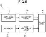
- a drive circuit 30 includes a sound driver circuit 32 to which a digital sound signal is input from a predetermined digital sound source 31.
- the sound driver circuit 32 is configured to convert the digital sound signal into a predetermined sound drive signal to supply the sound voice coil pattern 21 with drive current corresponding to the sound drive signal through the terminal portion 24.
- the drive circuit 30 further includes a microphone 33 to which external noise is input, and a noise cancellation circuit 34 to which an external noise signal is input from the microphone 33.
- the noise cancellation circuit 34 is configured to invert the phase of the noise signal from the microphone 33 and to use the phase-inverted signal as a noise cancellation signal to supply the noise cancellation voice coil pattern 22 with drive current corresponding to the noise cancellation signal through the terminal portion 24.
- the sound signal sent from the predetermined digital sound source 31 is converted into the sound drive signal by the sound driver circuit 32, and the drive current corresponding to the sound drive signal is supplied to the sound voice coil pattern 21.
- the external noise is input through the microphone 33, and is sent to the noise cancellation circuit 34.
- the noise cancellation circuit 34 inverts the phase of the noise signal from the microphone 33, and then, the drive current corresponding to the phase-inverted noise cancellation signal is supplied to the noise cancellation voice coil pattern 22.
- the sound voice coil pattern 21 and the noise cancellation voice coil pattern 22 are formed on the flexible circuit board 20, and the drive current corresponding to the sound signal and the drive current corresponding to the noise cancellation signal are supplied.
- the diaphragm 11 vibrates based on the composite signal of the sound signal and the noise cancellation signal. Consequently, sound of the sound signal can be output with the external noise being cancelled out. As a result, reproduced sound with a favorable sound quality can be obtained without noise signal influence on the sound signal.
- the noise cancellation voice coil pattern 22 is, in addition to the sound voice coil pattern 21, formed on the flexible circuit board 20.
- the surface of the diaphragm 11 can be hardened by addition of the noise cancellation voice coil pattern 22.
- a transmission speed by the diaphragm 11 can be increased, and worsening of high-frequency characteristics can be avoided.
- Figure 6 illustrates the second embodiment of the present invention.
- a noise cancellation voice coil pattern 22 is formed on each side of a sound voice coil pattern 21 formed on a flexible circuit board 20.
- the noise cancellation voice coil pattern 22 is formed on one side of the sound voice coil pattern 21 in the first embodiment.
- the noise cancellation voice coil pattern 22 is formed on one side of the sound voice coil pattern 21 in the first embodiment.
- the noise cancellation voice coil pattern 22 is formed on each side of the sound voice coil pattern 21 so that the diaphragm 11 can uniformly vibrate on the sound voice coil pattern 21.
- the sound voice coil pattern 21 and the noise cancellation voice coil patterns 22 are, in the present embodiment, formed on the flexible circuit board 20, and drive current corresponding to a sound signal and drive current corresponding to a noise cancellation signal are supplied.
- the diaphragm 11 vibrates based on a composite signal of the sound signal and the noise cancellation signal. Consequently, sound of the sound signal can be output with external noise being cancelled out.
- the noise cancellation voice coil pattern 22 is formed on each side of the sound voice coil pattern 21 on the flexible circuit board 20.
- the surface of the diaphragm 11 can be more hardened. As a result, a transmission speed by the diaphragm 11 can be increased, and worsening of high-frequency characteristics can be avoided.
- Figure 7 illustrates the third embodiment of the present invention.
- a speaker device using a plane diaphragm 11 tends to exhibit a smaller impedance and consume greater current. This might lead to an increase in power consumption of a power amplifier circuit, and therefore, leads to functioning of an overcurrent protection circuit.
- a noise cancellation voice coil pattern 22 is formed on each side of a sound voice coil pattern 21 as in the second embodiment, and end portions of the noise cancellation voice coil patterns 22 are electrically connected together to form a single long noise cancellation voice coil pattern 22 disposed on both sides of the sound voice coil pattern 21.
- the sound voice coil pattern 21 and the noise cancellation voice coil pattern 22 are, in the present embodiment, formed on a flexible circuit board 20, and drive current corresponding to a sound signal and a noise cancellation signal is supplied.
- the diaphragm 11 vibrates based on a composite signal of the sound signal and the noise cancellation signal. Consequently, sound of the sound signal can be output with external noise being cancelled out.
- the sound voice coil pattern 21 and the noise cancellation voice coil pattern 22 are formed on the flexible circuit board 20.
- the surface of the diaphragm 11 can be hardened. As a result, a transmission speed by the diaphragm 11 can be increased, and worsening of high-frequency characteristics can be avoided.
- the end portions of the noise cancellation voice coil patterns 22 are electrically connected together, and the noise cancellation voice coil pattern 22 is formed to have a great length dimension.
- the resistance of the noise cancellation voice coil pattern 22 increases, and therefore, the impedance of the noise cancellation voice coil pattern 22 can be enhanced. As a result, current consumption can be reduced. This can prevent functioning of the overcurrent protection circuit.
- drawing of a wiring pattern of the noise cancellation voice coil pattern 22 can be devised such that a great length dimension of the noise cancellation voice coil pattern 22 is ensured.
- the impedance of the noise cancellation voice coil pattern 22 can be increased.
- the impedance of the noise cancellation voice coil pattern 22 can be easily increased without such devising of drawing of the wiring pattern.
- Figure 8 illustrates the fourth embodiment of the present invention.
- the noise cancellation voice coil pattern 22 is, in the present embodiment, formed on each side of a sound voice coil pattern 21, and a resistor element 35 is connected to a middle portion of each noise cancellation voice coil pattern 22.
- the resistance of the noise cancellation voice coil pattern 22 is increased, and therefore, the impedance of the noise cancellation voice coil pattern 22 can be enhanced.
- the sound voice coil pattern 21 and the noise cancellation voice coil patterns 22 are, in the present embodiment, formed on a flexible circuit board 20, and drive current corresponding to a sound signal and a noise cancellation signal is supplied.
- a diaphragm 11 vibrates corresponding to a composite signal of the sound signal and the noise cancellation signal. Consequently, sound of the sound signal can be output with external noise being cancelled out.
- the sound voice coil pattern 21 and the noise cancellation voice coil patterns 22 are formed on the flexible circuit board 20.
- the surface of the diaphragm 11 can be hardened. As a result, a transmission speed by the diaphragm 11 can be increased, and worsening of high-frequency characteristics can be avoided.
- the resistor element 35 is connected to the middle portion of each noise cancellation voice coil pattern 22, the resistance of the noise cancellation voice coil pattern 22 can be increased by the resistor element 35.
- the impedance of the noise cancellation voice coil pattern 22 can be enhanced. As a result, current consumption can be reduced. This can prevent functioning of an overcurrent protection circuit.
- Figure 9 illustrates the fifth embodiment of the present invention.
- a reinforcement pattern 36 is formed between two adjacent patterns of a sound voice coil pattern 21 and/or a noise cancellation voice coil pattern 22 on a flexible circuit board 20.
- the reinforcement pattern 36 is a pattern formed of metal foil such as copper foil or foil of a hard material, for example.
- the flexible circuit board 20 is reinforced by the reinforcement patterns 36, and therefore, a transmission speed by a diaphragm 11 is increased.
- the sound voice coil pattern 21 and the noise cancellation voice coil pattern 22 are, in the present embodiment, formed on the flexible circuit board 20, and therefore, sound of a sound signal can be output with external noise being cancelled out.
- the sound voice coil pattern 21 and the noise cancellation voice coil pattern 22 are formed on the flexible circuit board 20, and the reinforcement pattern 36 is formed between two adjacent patterns of the sound voice coil pattern 21 and/or the noise cancellation voice coil pattern 22.
- the surface of the diaphragm 11 can be more hardened. As a result, the transmission speed by the diaphragm 11 can be increased, and high-frequency characteristics can be significantly improved.
- the sound voice coil pattern 21 and the noise cancellation voice coil pattern(s) 22 are formed on one side of the flexible circuit board 20, but may be formed on both sides of the flexible circuit board 20, for example.
- the sound voice coil pattern 21 may be formed on the flexible circuit board 20, and an insulating layer may be formed to cover the sound voice coil pattern 21. Then, the noise cancellation voice coil pattern(s) 22 may be formed on the surface of the insulating layer. With this configuration, the sound voice coil pattern 21 and the noise cancellation voice coil pattern(s) 22 may be formed on top of one another.
- the example where the N-pole and the S-pole of each magnet 13 are formed in the striped pattern and the sound voice coil pattern 21 and the noise cancellation voice coil pattern 22 are arranged meandering has been described.
- the magnetized state of the N-pole and the S-pole of each magnet 13 can be changed such that the sound voice coil pattern 21 and the noise cancellation voice coil pattern 22 are arranged according to the magnetized state of each magnet 13.
Landscapes
- Engineering & Computer Science (AREA)
- Physics & Mathematics (AREA)
- Acoustics & Sound (AREA)
- Signal Processing (AREA)
- Multimedia (AREA)
- Soundproofing, Sound Blocking, And Sound Damping (AREA)
- Audible-Bandwidth Dynamoelectric Transducers Other Than Pickups (AREA)
- Diaphragms For Electromechanical Transducers (AREA)
Abstract
Description
- The present invention relates to a speaker device.
- A noise cancellation technique of cancelling external noise at, e.g., a speaker device or headphones so that a user's ears can hear only musical sound has been typically in widespread use. According to such a noise cancellation technique, the external noise is detected by a microphone, and then, a noise cancellation signal with a phase opposite to that of the detected noise signal is generated. Subsequently, the noise cancellation signal is output from, e.g., the speaker device to cancel the external noise.
- Meanwhile, a full digital speaker device configured so that a digital signal can be directly input to a speaker has been recently developed. This full digital speaker device can directly transfer the digital signal to the speaker, and therefore, digital/analog conversion is no longer required. Thus, high-quality sound can be realized regardless of performance of a digital/analog converter.
- However, when the above-described noise cancellation technique is applied to the full digital speaker device, a delay of about 0.5 msec to 3 msec is, due to a delay caused by an arithmetic circuit of a digital filter portion provided in the full digital speaker device, caused after input of a noise signal until output of sound.
- For this reason, when an attempt is made to perform signal processing for the input noise signal to remove noise as in the typical noise cancellation technique, a noise-processed signal delay corresponding to the signal processing is also caused, and a delay in response to actual noise is caused. Thus, there is a problem that effective noise reduction cannot be performed.
- In order to prevent such a delay, a device has been typically proposed, which includes a speaker unit having a single diaphragm and two voice coils configured to drive the diaphragm and which is configured such that a musical sound signal is input to one of the voice coils and a noise cancellation signal based on a noise signal detected by a noise detection microphone is input to the other voice coil, for example (see Patent Literature 1).
- Patent Literature 1: Japanese Patent Laid-Open No.
2008-098988 - According to Patent Literature 1, the noise cancellation signal is input to one of the double wound voice coils, and in this manner, the single diaphragm is driven to cancel noise. Thus, the signal for noise cancellation can be simplified, and a delay in response to actual noise can be reduced as much as possible.
- However, the device of Patent Literature 1 is applied to a typical dynamic speaker. Due to an increase in the number of voice coils, the weights of the diaphragm and the voice coil portion themselves in the speaker device increase. For this reason, vibration of the diaphragm is reduced, leading to interruption of high-frequency characteristics and lowering of acoustic characteristics.
- The present invention has been made in view of the above-described points, and is intended to provide a speaker device configured so that a time lag between a sound signal and a noise cancellation signal can be prevented, worsening of high-frequency characteristics can be avoided, and acoustic characteristics can be improved.
- In order to accomplish the above-described objective, the present invention relates to a speaker device including a plane diaphragm. In the speaker device, the plane diaphragm includes a sound voice coil pattern to which drive current corresponding to a sound signal is supplied, and a noise cancellation voice coil pattern to which drive current corresponding to a noise cancellation signal is supplied, and the sound voice coil pattern and the noise cancellation voice coil pattern are formed corresponding to a formed magnetic field of a magnet.
- Moreover, in the above-described configuration, the plane diaphragm may be configured such that the sound voice coil pattern and the noise cancellation voice coil pattern are formed on a flexible circuit board. Further, in the above-described configuration, the noise cancellation voice coil pattern may be formed on one side of the sound voice coil pattern. In addition, in the above-described configuration, the noise cancellation voice coil pattern may be formed on each side of the sound voice coil pattern.
- Moreover, in the above-described configuration, the noise cancellation voice coil pattern may include a plurality of noise cancellation voice coil patterns, and end portions of the noise cancellation voice coil patterns may be electrically connected together to form a single noise cancellation voice coil pattern. Further, in the above-described configuration, a resistor element may be connected to a middle portion of the noise cancellation voice coil pattern. In addition, in the above-described configuration, a reinforcement pattern may be formed between two adjacent patterns of the sound voice coil pattern and/or the noise cancellation voice coil pattern of the plane diaphragm.
- According to the present invention, the sound voice coil pattern to which the drive current corresponding to the sound signal is supplied and the noise cancellation voice coil pattern to which the drive current corresponding to the noise cancellation signal is supplied are formed, and therefore, reproduced sound with a favorable sound quality can be obtained without noise signal influence on the sound signal. Moreover, since the sound voice coil pattern and the noise cancellation voice coil pattern are formed, the surface of the diaphragm can be hardened. As a result, a transmission speed by the diaphragm can be increased, and worsening of high-frequency characteristics can be avoided.
-
- [
Figure 1] Figure 1 is an exploded perspective view of a speaker device, illustrating a first embodiment of a speaker device of the present invention. - [
Figure 2] Figure 2 is a longitudinal sectional view of the speaker device. - [
Figure 3] Figure 3 is a plan view of a diaphragm. - [
Figure 4] Figure 4 is an enlarged partial view of the diaphragm in a frame indicated by a chain line ofFigure 3 . - [
Figure 5] Figure 5 is a block diagram of a drive circuit. - [
Figure 6] Figure 6 is an enlarged partial view of a diaphragm, illustrating a second embodiment of the speaker device of the present invention. - [
Figure 7] Figure 7 is an enlarged partial view of a diaphragm, illustrating a third embodiment of the speaker device of the present invention. - [
Figure 8] Figure 8 is an enlarged partial view of a diaphragm, illustrating a fourth embodiment of the speaker device of the present invention. - [
Figure 9] Figure 9 is an enlarged partial view of a diaphragm, illustrating a fifth embodiment of the speaker device of the present invention. - Embodiments of a speaker device of the present invention will be described below with reference to drawings.
-
Figure 1 is an exploded perspective view of the speaker device, andFigure 2 is a longitudinal sectional view of the speaker device.Figure 3 is a plan view of a diaphragm, andFigure 4 is an enlarged partial view of the diaphragm in a frame indicated by a chain line ofFigure 3 . - In the present embodiment, an example of a full digital speaker device using a plane diaphragm is described as the speaker device.
- A
speaker device 10 of the present embodiment includes adiaphragm 11, a pair ofmagnets 13 vertically sandwiching thediaphragm 11 with abuffer member 12 being interposed between eachmagnet 13 and thediaphragm 11, and a pair ofholding members 14 covering all of these members from upper and lower sides. - The
diaphragm 11 is formed of a thin film-shapedflexible circuit board 20, and a soundvoice coil pattern 21 to which drive current is supplied based on a sound signal is formed on one surface of theflexible circuit board 20. As illustrated inFigures 3 and4 , the soundvoice coil pattern 21 is formed such that a plurality of conductive wire patterns meander across the entirety of theflexible circuit board 20. - Moreover, in the present embodiment, a single noise cancellation
voice coil pattern 22 is, on one side of the soundvoice coil pattern 21 on theflexible circuit board 20, formed to meander substantially in parallel to the soundvoice coil pattern 21, as illustrated inFigure 3 . - Note that in
Figures 4 ,6 , and9 , the soundvoice coil pattern 21 is indicated by a solid line, and the noise cancellationvoice coil pattern 22 is indicated by a chain line, for the sake of description. - A conductive
wire drawing portion 23 configured to draw the soundvoice coil pattern 21 and the noise cancellationvoice coil pattern 22 to the outside is provided integrally with one side of thediaphragm 11, and a tip end portion of the conductivewire drawing portion 23 is provided with aterminal portion 24 connected to end portions of the soundvoice coil pattern 21 and the noise cancellationvoice coil pattern 22. - It is configured such that drive current is applied from the
terminal portion 24 based on a predetermined digital sound signal and a predetermined analog noise cancellation signal. - Moreover, as illustrated in
Figure 2 , themagnets 13 are formed in such a striped pattern that the N-pole and the S-pole are alternatively positioned along the line of the voice coil pattern. - A magnetic field component vertical to the surface of each
magnet 13 is greatest in the vicinity of the N-pole and the S-pole, and is smallest in the vicinity of the boundary between the N-pole and the S-pole. On the other hand, a horizontal magnetic field component parallel to the surface of eachmagnet 13 is smallest in the vicinity of the N-pole and the S-pole, and is greatest in the vicinity of the boundary between the N-pole and the S-pole. Thus, a magnetic field component contributing to vibration of thediaphragm 11 in the thickness direction thereof is not a vertical component but a horizontal component (the Fleming's left hand rule). - Thus, linear portions of the sound
voice coil pattern 21 and the noise cancellationvoice coil pattern 22 are arranged at positions corresponding to the vicinity of the boundary between the N-pole and the S-pole such that lines of magnetic force extend in the direction intersecting the linear portions of the soundvoice coil pattern 21 and the noise cancellationvoice coil pattern 22 in the plane of thediaphragm 11. - Thus, in the present embodiment, it is configured such that the sound
voice coil pattern 21 and the noise cancellationvoice coil pattern 22 are arranged at the boundary between the N-pole and the S-pole. When drive current is applied to the soundvoice coil pattern 21 and the noise cancellationvoice coil pattern 22, electromagnetic force is most efficiently generated by interaction between the drive current and a magnetic field, and thediaphragm 11 vibrates in the thickness direction thereof. - As illustrated in
Figure 1 , eachmagnet 13 is provided with a plurality of through-holes 25 through which sound output from thediaphragm 11 passes. As described above, the soundvoice coil pattern 21 and the noise cancellationvoice coil pattern 22 are arranged at the boundary between the N-pole and the S-pole so that thediaphragm 11 can efficiently vibrates at such a boundary. Thus, each through-hole 25 is preferably formed at a position corresponding to the boundary between the N-pole and the S-pole. - Each
buffer member 12 is made of a soft material, and has a function to allow sound to pass through thebuffer member 12. Thebuffer member 12 is made of nonwoven fabric, for example. Thebuffer member 12 is formed to have the substantially same size as that of thediaphragm 11, and forms a predetermined gap between thediaphragm 11 and themagnet 13. Thebuffer member 12 is configured to prevent noise generation due to contact between thediaphragm 11 and themagnet 13 in driving of thediaphragm 11. Depending on the thickness and material of thebuffer member 12, a plurality ofbuffer members 12 may be used in the form of a stack, if necessary. - Each holding
member 14 is made of a hard material such as metal. In the state in which thediaphragm 11, thebuffer members 12, and themagnets 13 are sandwiched between the holdingmembers 14, not-shown screws etc. are screwed into the outer periphery of each holdingmember 14, and therefore, thediaphragm 11 is held and fixed between the pair ofmagnets 13 with a predetermined gap being formed between thediaphragm 11 and eachmagnet 13. Moreover, the holdingmember 14 is provided with through-holes 26 at positions similar to those of the through-holes 25 of themagnet 13, and each through-hole 26 allows sound from thediaphragm 11 to be efficiently emitted to the outside. - Next, a drive circuit of the
speaker device 10 described above will be described with reference toFigure 5 . - As illustrated in
Figure 5 , adrive circuit 30 includes asound driver circuit 32 to which a digital sound signal is input from a predetermined digitalsound source 31. Thesound driver circuit 32 is configured to convert the digital sound signal into a predetermined sound drive signal to supply the soundvoice coil pattern 21 with drive current corresponding to the sound drive signal through theterminal portion 24. - The
drive circuit 30 further includes amicrophone 33 to which external noise is input, and anoise cancellation circuit 34 to which an external noise signal is input from themicrophone 33. Thenoise cancellation circuit 34 is configured to invert the phase of the noise signal from themicrophone 33 and to use the phase-inverted signal as a noise cancellation signal to supply the noise cancellationvoice coil pattern 22 with drive current corresponding to the noise cancellation signal through theterminal portion 24. - Next, features of the present embodiment will be described.
- In the present embodiment, the sound signal sent from the predetermined digital
sound source 31 is converted into the sound drive signal by thesound driver circuit 32, and the drive current corresponding to the sound drive signal is supplied to the soundvoice coil pattern 21. - Meanwhile, the external noise is input through the
microphone 33, and is sent to thenoise cancellation circuit 34. Thenoise cancellation circuit 34 inverts the phase of the noise signal from themicrophone 33, and then, the drive current corresponding to the phase-inverted noise cancellation signal is supplied to the noise cancellationvoice coil pattern 22. - Since the drive current corresponding to the sound signal and the drive current corresponding to the noise cancellation signal are supplied, electromagnetic force is generated by interaction between each type of drive current and the magnetic field of each
magnet 13, and thediaphragm 11 vibrates in the thickness direction thereof. At this point, since not only the drive current corresponding to the sound signal but also the drive current corresponding to the noise cancellation signal are supplied, thediaphragm 11 vibrates based on a composite signal of the sound signal and the noise cancellation signal. Thus, sound of the sound signal can be output with the external noise being cancelled out. - As described above, in the present embodiment, the sound
voice coil pattern 21 and the noise cancellationvoice coil pattern 22 are formed on theflexible circuit board 20, and the drive current corresponding to the sound signal and the drive current corresponding to the noise cancellation signal are supplied. Thus, thediaphragm 11 vibrates based on the composite signal of the sound signal and the noise cancellation signal. Consequently, sound of the sound signal can be output with the external noise being cancelled out. As a result, reproduced sound with a favorable sound quality can be obtained without noise signal influence on the sound signal. - Moreover, in the present embodiment, the noise cancellation
voice coil pattern 22 is, in addition to the soundvoice coil pattern 21, formed on theflexible circuit board 20. Thus, the surface of thediaphragm 11 can be hardened by addition of the noise cancellationvoice coil pattern 22. As a result, a transmission speed by thediaphragm 11 can be increased, and worsening of high-frequency characteristics can be avoided. - Next, a second embodiment of the present invention will be described.
-
Figure 6 illustrates the second embodiment of the present invention. In the present embodiment, a noise cancellationvoice coil pattern 22 is formed on each side of a soundvoice coil pattern 21 formed on aflexible circuit board 20. - That is, the noise cancellation
voice coil pattern 22 is formed on one side of the soundvoice coil pattern 21 in the first embodiment. However, in the case of forming the noise cancellationvoice coil pattern 22 on one side of the soundvoice coil pattern 21, there is a probability that the amplitude of thediaphragm 11 is non-uniform. - For this reason, in the present embodiment, the noise cancellation
voice coil pattern 22 is formed on each side of the soundvoice coil pattern 21 so that thediaphragm 11 can uniformly vibrate on the soundvoice coil pattern 21. - As in the first embodiment, the sound
voice coil pattern 21 and the noise cancellationvoice coil patterns 22 are, in the present embodiment, formed on theflexible circuit board 20, and drive current corresponding to a sound signal and drive current corresponding to a noise cancellation signal are supplied. Thus, thediaphragm 11 vibrates based on a composite signal of the sound signal and the noise cancellation signal. Consequently, sound of the sound signal can be output with external noise being cancelled out. - Moreover, the noise cancellation
voice coil pattern 22 is formed on each side of the soundvoice coil pattern 21 on theflexible circuit board 20. Thus, as compared to the first embodiment, the surface of thediaphragm 11 can be more hardened. As a result, a transmission speed by thediaphragm 11 can be increased, and worsening of high-frequency characteristics can be avoided. - Next, a third embodiment of the present invention will be described.
-
Figure 7 illustrates the third embodiment of the present invention. In general, as compared to a dynamic speaker device, a speaker device using aplane diaphragm 11 tends to exhibit a smaller impedance and consume greater current. This might lead to an increase in power consumption of a power amplifier circuit, and therefore, leads to functioning of an overcurrent protection circuit. - For this reason, in the present embodiment, a noise cancellation
voice coil pattern 22 is formed on each side of a soundvoice coil pattern 21 as in the second embodiment, and end portions of the noise cancellationvoice coil patterns 22 are electrically connected together to form a single long noise cancellationvoice coil pattern 22 disposed on both sides of the soundvoice coil pattern 21. - With this noise cancellation
voice coil pattern 22 having a great length dimension, the resistance of the noise cancellationvoice coil pattern 22 increases, and therefore, the impedance of the noise cancellationvoice coil pattern 22 can be enhanced. - As in each of the above-described embodiments, the sound
voice coil pattern 21 and the noise cancellationvoice coil pattern 22 are, in the present embodiment, formed on aflexible circuit board 20, and drive current corresponding to a sound signal and a noise cancellation signal is supplied. Thus, thediaphragm 11 vibrates based on a composite signal of the sound signal and the noise cancellation signal. Consequently, sound of the sound signal can be output with external noise being cancelled out. - Moreover, the sound
voice coil pattern 21 and the noise cancellationvoice coil pattern 22 are formed on theflexible circuit board 20. Thus, the surface of thediaphragm 11 can be hardened. As a result, a transmission speed by thediaphragm 11 can be increased, and worsening of high-frequency characteristics can be avoided. - Further, the end portions of the noise cancellation
voice coil patterns 22 are electrically connected together, and the noise cancellationvoice coil pattern 22 is formed to have a great length dimension. Thus, the resistance of the noise cancellationvoice coil pattern 22 increases, and therefore, the impedance of the noise cancellationvoice coil pattern 22 can be enhanced. As a result, current consumption can be reduced. This can prevent functioning of the overcurrent protection circuit. - Note that in the first and second embodiments, drawing of a wiring pattern of the noise cancellation
voice coil pattern 22 can be devised such that a great length dimension of the noise cancellationvoice coil pattern 22 is ensured. Thus, the impedance of the noise cancellationvoice coil pattern 22 can be increased. However, in the present embodiment, the impedance of the noise cancellationvoice coil pattern 22 can be easily increased without such devising of drawing of the wiring pattern. - Next, a fourth embodiment of the present invention will be described.
-
Figure 8 illustrates the fourth embodiment of the present invention. In order to increase the impedance of a noise cancellationvoice coil pattern 22, the noise cancellationvoice coil pattern 22 is, in the present embodiment, formed on each side of a soundvoice coil pattern 21, and aresistor element 35 is connected to a middle portion of each noise cancellationvoice coil pattern 22. - With the
resistor element 35 connected to each noise cancellationvoice coil pattern 22, the resistance of the noise cancellationvoice coil pattern 22 is increased, and therefore, the impedance of the noise cancellationvoice coil pattern 22 can be enhanced. - As in each of the above-described embodiments, the sound
voice coil pattern 21 and the noise cancellationvoice coil patterns 22 are, in the present embodiment, formed on aflexible circuit board 20, and drive current corresponding to a sound signal and a noise cancellation signal is supplied. Thus, adiaphragm 11 vibrates corresponding to a composite signal of the sound signal and the noise cancellation signal. Consequently, sound of the sound signal can be output with external noise being cancelled out. - Moreover, the sound
voice coil pattern 21 and the noise cancellationvoice coil patterns 22 are formed on theflexible circuit board 20. Thus, the surface of thediaphragm 11 can be hardened. As a result, a transmission speed by thediaphragm 11 can be increased, and worsening of high-frequency characteristics can be avoided. - Further, since the
resistor element 35 is connected to the middle portion of each noise cancellationvoice coil pattern 22, the resistance of the noise cancellationvoice coil pattern 22 can be increased by theresistor element 35. Thus, the impedance of the noise cancellationvoice coil pattern 22 can be enhanced. As a result, current consumption can be reduced. This can prevent functioning of an overcurrent protection circuit. - Next, a fifth embodiment of the present invention will be described.
-
Figure 9 illustrates the fifth embodiment of the present invention. In the present embodiment, areinforcement pattern 36 is formed between two adjacent patterns of a soundvoice coil pattern 21 and/or a noise cancellationvoice coil pattern 22 on aflexible circuit board 20. - The
reinforcement pattern 36 is a pattern formed of metal foil such as copper foil or foil of a hard material, for example. Theflexible circuit board 20 is reinforced by thereinforcement patterns 36, and therefore, a transmission speed by adiaphragm 11 is increased. - As in each of the above-described embodiments, the sound
voice coil pattern 21 and the noise cancellationvoice coil pattern 22 are, in the present embodiment, formed on theflexible circuit board 20, and therefore, sound of a sound signal can be output with external noise being cancelled out. - Moreover, the sound
voice coil pattern 21 and the noise cancellationvoice coil pattern 22 are formed on theflexible circuit board 20, and thereinforcement pattern 36 is formed between two adjacent patterns of the soundvoice coil pattern 21 and/or the noise cancellationvoice coil pattern 22. Thus, the surface of thediaphragm 11 can be more hardened. As a result, the transmission speed by thediaphragm 11 can be increased, and high-frequency characteristics can be significantly improved. - Note that aspects of the present invention have been described in the above-described embodiments, and the present invention is not limited to these embodiments.
- For example, in each of the above-described embodiments, the case where the single or double noise cancellation
voice coil patterns 22 are formed has been described. However, three or more noise cancellationvoice coil patterns 22 may be formed. - Moreover, in each of the above-described embodiments, the sound
voice coil pattern 21 and the noise cancellation voice coil pattern(s) 22 are formed on one side of theflexible circuit board 20, but may be formed on both sides of theflexible circuit board 20, for example. - For example, the sound
voice coil pattern 21 may be formed on theflexible circuit board 20, and an insulating layer may be formed to cover the soundvoice coil pattern 21. Then, the noise cancellation voice coil pattern(s) 22 may be formed on the surface of the insulating layer. With this configuration, the soundvoice coil pattern 21 and the noise cancellation voice coil pattern(s) 22 may be formed on top of one another. - Further, in each of the above-described embodiments, the example where the N-pole and the S-pole of each
magnet 13 are formed in the striped pattern and the soundvoice coil pattern 21 and the noise cancellationvoice coil pattern 22 are arranged meandering has been described. However, the magnetized state of the N-pole and the S-pole of eachmagnet 13 can be changed such that the soundvoice coil pattern 21 and the noise cancellationvoice coil pattern 22 are arranged according to the magnetized state of eachmagnet 13. -
- 10
- speaker device
- 11
- diaphragm
- 12
- buffer member
- 13
- magnet
- 14
- holding member
- 20
- flexible circuit board
- 21
- sound voice coil pattern
- 22
- noise cancellation voice coil pattern
- 23
- conductive wire drawing portion
- 24
- terminal portion
- 25, 26
- through-hole
- 30
- drive circuit
- 31
- digital sound source
- 32
- sound driver circuit
- 33
- microphone
- 34
- noise cancellation circuit
- 35
- resistor element
- 36
- reinforcement pattern
Claims (7)
- A speaker device comprising:a plane diaphragm,wherein the plane diaphragm includesa sound voice coil pattern to which drive current corresponding to a sound signal is supplied, anda noise cancellation voice coil pattern to which drive current corresponding to a noise cancellation signal is supplied, andwherein the sound voice coil pattern and the noise cancellation voice coil pattern are formed corresponding to a formed magnetic field of a magnet.
- The speaker device according to claim 1, wherein
the plane diaphragm is configured such that the sound voice coil pattern and the noise cancellation voice coil pattern are formed on a flexible circuit board. - The speaker device according to claim 1 or 2, wherein
the noise cancellation voice coil pattern is formed on one side of the sound voice coil pattern. - The speaker device according to claim 1 or 2, wherein
the noise cancellation voice coil pattern is formed on each side of the sound voice coil pattern. - The speaker device according to claim 1 or 2, wherein
the noise cancellation voice coil pattern includes a plurality of noise cancellation voice coil patterns, and end portions of the noise cancellation voice coil patterns are electrically connected together to form a single noise cancellation voice coil pattern. - The speaker device according to claim 1 or 2, wherein
a resistor element is connected to a middle portion of the noise cancellation voice coil pattern. - The speaker device according to any one of claims 1 to 6, wherein
a reinforcement pattern is formed between two adjacent patterns of the sound voice coil pattern and/or the noise cancellation voice coil pattern of the plane diaphragm.
Applications Claiming Priority (2)
| Application Number | Priority Date | Filing Date | Title |
|---|---|---|---|
| JP2014136653A JP6499408B2 (en) | 2014-07-02 | 2014-07-02 | Speaker device |
| PCT/JP2015/068952 WO2016002830A1 (en) | 2014-07-02 | 2015-07-01 | Speaker device |
Publications (3)
| Publication Number | Publication Date |
|---|---|
| EP3166335A1 true EP3166335A1 (en) | 2017-05-10 |
| EP3166335A4 EP3166335A4 (en) | 2018-02-28 |
| EP3166335B1 EP3166335B1 (en) | 2019-01-30 |
Family
ID=55019360
Family Applications (1)
| Application Number | Title | Priority Date | Filing Date |
|---|---|---|---|
| EP15815567.1A Active EP3166335B1 (en) | 2014-07-02 | 2015-07-01 | Speaker device |
Country Status (5)
| Country | Link |
|---|---|
| US (1) | US9854366B2 (en) |
| EP (1) | EP3166335B1 (en) |
| JP (1) | JP6499408B2 (en) |
| CN (1) | CN106465017B (en) |
| WO (1) | WO2016002830A1 (en) |
Families Citing this family (6)
| Publication number | Priority date | Publication date | Assignee | Title |
|---|---|---|---|---|
| JPWO2018225181A1 (en) * | 2017-06-07 | 2020-04-09 | 株式会社 Trigence Semiconductor | Speaker device and speaker unit |
| CN107809693B (en) * | 2017-11-20 | 2019-12-17 | 中山奥凯华泰电子有限公司 | Double-voice-coil earphone |
| WO2020003381A1 (en) | 2018-06-26 | 2020-01-02 | 昭人 花田 | Voice coil diaphragm |
| CN109982212A (en) * | 2019-03-29 | 2019-07-05 | 努比亚技术有限公司 | Loudspeaker and electronic equipment |
| CN112104951A (en) * | 2019-06-17 | 2020-12-18 | 香港大学浙江科学技术研究院 | Adjustable sound absorption board |
| CN111491239A (en) * | 2020-04-15 | 2020-08-04 | 天津黎明时代信息技术有限公司 | Active digital surface sound source device with detection module and detection method thereof |
Family Cites Families (16)
| Publication number | Priority date | Publication date | Assignee | Title |
|---|---|---|---|---|
| JPS5288015A (en) * | 1976-01-16 | 1977-07-22 | Sharp Corp | Speaker |
| JPS5393126U (en) * | 1976-12-27 | 1978-07-29 | ||
| JPS63102597A (en) * | 1986-10-20 | 1988-05-07 | Matsushita Electric Ind Co Ltd | Speaker |
| JP3003344U (en) | 1994-04-19 | 1994-10-18 | フオスター電機株式会社 | ANR headphones |
| US5757935A (en) * | 1996-03-01 | 1998-05-26 | Electronics And Telecommunications Research Institute | Audio listening device for the hearing impaired |
| JP3282656B2 (en) * | 1997-04-14 | 2002-05-20 | 株式会社ケンウッド | Multi-point speaker |
| JPH11136794A (en) * | 1997-08-29 | 1999-05-21 | Victor Co Of Japan Ltd | Electroacoustic converter |
| JP3344385B2 (en) * | 1999-10-22 | 2002-11-11 | ヤマハ株式会社 | Vibration source drive |
| KR100547357B1 (en) * | 2004-03-30 | 2006-01-26 | 삼성전기주식회사 | Speaker for mobile terminal and manufacturing method thereof |
| CN101180916B (en) * | 2005-02-25 | 2011-07-20 | 诺基亚公司 | Audio transducer component |
| JP2008032767A (en) * | 2006-07-26 | 2008-02-14 | Matsushita Electric Ind Co Ltd | Active noise reduction system |
| JP2008098988A (en) | 2006-10-12 | 2008-04-24 | Audio Technica Corp | Headphones |
| JP5078850B2 (en) * | 2008-11-17 | 2012-11-21 | 三菱電機エンジニアリング株式会社 | Flat speaker |
| KR101057842B1 (en) * | 2009-04-23 | 2011-08-19 | 미쓰비시 덴끼 엔지니어링 가부시키가이샤 | Electronic converter |
| JP2011151599A (en) | 2010-01-21 | 2011-08-04 | Foster Electric Co Ltd | Low profile multiway speaker |
| JP2015195419A (en) * | 2012-08-17 | 2015-11-05 | 株式会社プロトロ | Electroacoustic conversion device |
-
2014
- 2014-07-02 JP JP2014136653A patent/JP6499408B2/en active Active
-
2015
- 2015-07-01 EP EP15815567.1A patent/EP3166335B1/en active Active
- 2015-07-01 CN CN201580032636.7A patent/CN106465017B/en active Active
- 2015-07-01 US US15/308,669 patent/US9854366B2/en active Active
- 2015-07-01 WO PCT/JP2015/068952 patent/WO2016002830A1/en active Application Filing
Also Published As
| Publication number | Publication date |
|---|---|
| US20170150274A1 (en) | 2017-05-25 |
| JP6499408B2 (en) | 2019-04-10 |
| EP3166335B1 (en) | 2019-01-30 |
| WO2016002830A1 (en) | 2016-01-07 |
| US9854366B2 (en) | 2017-12-26 |
| CN106465017B (en) | 2019-10-15 |
| EP3166335A4 (en) | 2018-02-28 |
| CN106465017A (en) | 2017-02-22 |
| JP2016015616A (en) | 2016-01-28 |
Similar Documents
| Publication | Publication Date | Title |
|---|---|---|
| US9854366B2 (en) | Speaker device | |
| JP6132492B2 (en) | Voice coil speaker | |
| EP3322543B1 (en) | Vibrating actuator | |
| KR20110063792A (en) | Methods and apparatus for reduced distortion balanced armature devices | |
| US11076235B2 (en) | Speaker assembly | |
| CN102711025A (en) | Magnetic circuit system and loudspeaker thereof | |
| US11838736B2 (en) | Electromagnetic actuator for a speaker or a sound transducer with a multimetal layer connection between the voice coil and the magnet system | |
| US11678123B2 (en) | Electromagnetic actuator for a speaker or a sound transducer with a high-strength metal connection between the voice coil and the magnet system | |
| JP6458276B2 (en) | Voice coil, electroacoustic transducer, headphones and diaphragm | |
| JP6301699B2 (en) | Electronics | |
| JP6667364B2 (en) | Flat speaker and method for improving its frequency characteristics | |
| CN109587609B (en) | Sound producing device | |
| CN109379683B (en) | Sounding device | |
| WO2014002680A1 (en) | Voice coil speaker | |
| US10602252B2 (en) | Electrodynamic loudspeaker membrane with internally molded electrical connection | |
| CN112653971B (en) | Sound production device and terminal equipment | |
| JP2005184589A (en) | Voice coil for electroacoustic transducer, electroacoustic transducer employing the voice coil, and electronic device and apparatus employing electroacoustic transducer | |
| JP3934535B2 (en) | Electroacoustic transducer | |
| US20220385161A1 (en) | Four magnet motor structure for a speaker | |
| JP2010124094A (en) | Electromagnetic converter | |
| JP2008148096A (en) | Dynamic microphone | |
| JP2017005413A (en) | Diaphragm, electrodynamic speaker, headphone unit, and headphone | |
| KR101148834B1 (en) | A sound converting apparatus | |
| JP2004228655A (en) | Electroacoustic transducer | |
| CN103929700A (en) | Horn driven by balanced magnets |
Legal Events
| Date | Code | Title | Description |
|---|---|---|---|
| STAA | Information on the status of an ep patent application or granted ep patent |
Free format text: STATUS: THE INTERNATIONAL PUBLICATION HAS BEEN MADE |
|
| PUAI | Public reference made under article 153(3) epc to a published international application that has entered the european phase |
Free format text: ORIGINAL CODE: 0009012 |
|
| STAA | Information on the status of an ep patent application or granted ep patent |
Free format text: STATUS: REQUEST FOR EXAMINATION WAS MADE |
|
| 17P | Request for examination filed |
Effective date: 20170103 |
|
| AK | Designated contracting states |
Kind code of ref document: A1 Designated state(s): AL AT BE BG CH CY CZ DE DK EE ES FI FR GB GR HR HU IE IS IT LI LT LU LV MC MK MT NL NO PL PT RO RS SE SI SK SM TR |
|
| AX | Request for extension of the european patent |
Extension state: BA ME |
|
| DAV | Request for validation of the european patent (deleted) | ||
| DAX | Request for extension of the european patent (deleted) | ||
| A4 | Supplementary search report drawn up and despatched |
Effective date: 20180130 |
|
| RIC1 | Information provided on ipc code assigned before grant |
Ipc: H04R 7/06 20060101ALN20180124BHEP Ipc: G10K 11/178 20060101ALI20180124BHEP Ipc: H04R 1/00 20060101ALN20180124BHEP Ipc: H04R 9/02 20060101ALN20180124BHEP Ipc: H04R 9/04 20060101AFI20180124BHEP Ipc: H04R 1/10 20060101ALN20180124BHEP Ipc: H04R 9/06 20060101ALI20180124BHEP |
|
| GRAP | Despatch of communication of intention to grant a patent |
Free format text: ORIGINAL CODE: EPIDOSNIGR1 |
|
| RIC1 | Information provided on ipc code assigned before grant |
Ipc: H04R 9/02 20060101ALN20180518BHEP Ipc: H04R 1/10 20060101ALN20180518BHEP Ipc: H04R 7/06 20060101ALN20180518BHEP Ipc: G10K 11/178 20060101ALI20180518BHEP Ipc: H04R 9/06 20060101ALI20180518BHEP Ipc: H04R 9/04 20060101AFI20180518BHEP Ipc: H04R 1/00 20060101ALN20180518BHEP |
|
| STAA | Information on the status of an ep patent application or granted ep patent |
Free format text: STATUS: GRANT OF PATENT IS INTENDED |
|
| INTG | Intention to grant announced |
Effective date: 20180628 |
|
| GRAJ | Information related to disapproval of communication of intention to grant by the applicant or resumption of examination proceedings by the epo deleted |
Free format text: ORIGINAL CODE: EPIDOSDIGR1 |
|
| STAA | Information on the status of an ep patent application or granted ep patent |
Free format text: STATUS: REQUEST FOR EXAMINATION WAS MADE |
|
| REG | Reference to a national code |
Ref country code: DE Ref legal event code: R079 Ref document number: 602015024149 Country of ref document: DE Free format text: PREVIOUS MAIN CLASS: H04R0009000000 Ipc: H04R0009040000 |
|
| GRAP | Despatch of communication of intention to grant a patent |
Free format text: ORIGINAL CODE: EPIDOSNIGR1 |
|
| STAA | Information on the status of an ep patent application or granted ep patent |
Free format text: STATUS: GRANT OF PATENT IS INTENDED |
|
| INTC | Intention to grant announced (deleted) | ||
| RIC1 | Information provided on ipc code assigned before grant |
Ipc: H04R 7/06 20060101ALN20180910BHEP Ipc: G10K 11/178 20060101ALI20180910BHEP Ipc: H04R 1/10 20060101ALN20180910BHEP Ipc: H04R 9/04 20060101AFI20180910BHEP Ipc: H04R 9/06 20060101ALI20180910BHEP Ipc: H04R 9/02 20060101ALN20180910BHEP Ipc: H04R 1/00 20060101ALN20180910BHEP |
|
| INTG | Intention to grant announced |
Effective date: 20181009 |
|
| GRAS | Grant fee paid |
Free format text: ORIGINAL CODE: EPIDOSNIGR3 |
|
| GRAA | (expected) grant |
Free format text: ORIGINAL CODE: 0009210 |
|
| STAA | Information on the status of an ep patent application or granted ep patent |
Free format text: STATUS: THE PATENT HAS BEEN GRANTED |
|
| AK | Designated contracting states |
Kind code of ref document: B1 Designated state(s): AL AT BE BG CH CY CZ DE DK EE ES FI FR GB GR HR HU IE IS IT LI LT LU LV MC MK MT NL NO PL PT RO RS SE SI SK SM TR |
|
| REG | Reference to a national code |
Ref country code: GB Ref legal event code: FG4D |
|
| REG | Reference to a national code |
Ref country code: CH Ref legal event code: EP |
|
| REG | Reference to a national code |
Ref country code: AT Ref legal event code: REF Ref document number: 1094180 Country of ref document: AT Kind code of ref document: T Effective date: 20190215 |
|
| REG | Reference to a national code |
Ref country code: IE Ref legal event code: FG4D |
|
| REG | Reference to a national code |
Ref country code: DE Ref legal event code: R096 Ref document number: 602015024149 Country of ref document: DE |
|
| REG | Reference to a national code |
Ref country code: LT Ref legal event code: MG4D |
|
| REG | Reference to a national code |
Ref country code: NL Ref legal event code: MP Effective date: 20190130 |
|
| PG25 | Lapsed in a contracting state [announced via postgrant information from national office to epo] |
Ref country code: SE Free format text: LAPSE BECAUSE OF FAILURE TO SUBMIT A TRANSLATION OF THE DESCRIPTION OR TO PAY THE FEE WITHIN THE PRESCRIBED TIME-LIMIT Effective date: 20190130 Ref country code: NL Free format text: LAPSE BECAUSE OF FAILURE TO SUBMIT A TRANSLATION OF THE DESCRIPTION OR TO PAY THE FEE WITHIN THE PRESCRIBED TIME-LIMIT Effective date: 20190130 Ref country code: ES Free format text: LAPSE BECAUSE OF FAILURE TO SUBMIT A TRANSLATION OF THE DESCRIPTION OR TO PAY THE FEE WITHIN THE PRESCRIBED TIME-LIMIT Effective date: 20190130 Ref country code: PL Free format text: LAPSE BECAUSE OF FAILURE TO SUBMIT A TRANSLATION OF THE DESCRIPTION OR TO PAY THE FEE WITHIN THE PRESCRIBED TIME-LIMIT Effective date: 20190130 Ref country code: NO Free format text: LAPSE BECAUSE OF FAILURE TO SUBMIT A TRANSLATION OF THE DESCRIPTION OR TO PAY THE FEE WITHIN THE PRESCRIBED TIME-LIMIT Effective date: 20190430 Ref country code: PT Free format text: LAPSE BECAUSE OF FAILURE TO SUBMIT A TRANSLATION OF THE DESCRIPTION OR TO PAY THE FEE WITHIN THE PRESCRIBED TIME-LIMIT Effective date: 20190530 Ref country code: FI Free format text: LAPSE BECAUSE OF FAILURE TO SUBMIT A TRANSLATION OF THE DESCRIPTION OR TO PAY THE FEE WITHIN THE PRESCRIBED TIME-LIMIT Effective date: 20190130 Ref country code: LT Free format text: LAPSE BECAUSE OF FAILURE TO SUBMIT A TRANSLATION OF THE DESCRIPTION OR TO PAY THE FEE WITHIN THE PRESCRIBED TIME-LIMIT Effective date: 20190130 |
|
| REG | Reference to a national code |
Ref country code: AT Ref legal event code: MK05 Ref document number: 1094180 Country of ref document: AT Kind code of ref document: T Effective date: 20190130 |
|
| PG25 | Lapsed in a contracting state [announced via postgrant information from national office to epo] |
Ref country code: IS Free format text: LAPSE BECAUSE OF FAILURE TO SUBMIT A TRANSLATION OF THE DESCRIPTION OR TO PAY THE FEE WITHIN THE PRESCRIBED TIME-LIMIT Effective date: 20190530 Ref country code: BG Free format text: LAPSE BECAUSE OF FAILURE TO SUBMIT A TRANSLATION OF THE DESCRIPTION OR TO PAY THE FEE WITHIN THE PRESCRIBED TIME-LIMIT Effective date: 20190430 Ref country code: HR Free format text: LAPSE BECAUSE OF FAILURE TO SUBMIT A TRANSLATION OF THE DESCRIPTION OR TO PAY THE FEE WITHIN THE PRESCRIBED TIME-LIMIT Effective date: 20190130 Ref country code: RS Free format text: LAPSE BECAUSE OF FAILURE TO SUBMIT A TRANSLATION OF THE DESCRIPTION OR TO PAY THE FEE WITHIN THE PRESCRIBED TIME-LIMIT Effective date: 20190130 Ref country code: GR Free format text: LAPSE BECAUSE OF FAILURE TO SUBMIT A TRANSLATION OF THE DESCRIPTION OR TO PAY THE FEE WITHIN THE PRESCRIBED TIME-LIMIT Effective date: 20190501 Ref country code: LV Free format text: LAPSE BECAUSE OF FAILURE TO SUBMIT A TRANSLATION OF THE DESCRIPTION OR TO PAY THE FEE WITHIN THE PRESCRIBED TIME-LIMIT Effective date: 20190130 |
|
| PG25 | Lapsed in a contracting state [announced via postgrant information from national office to epo] |
Ref country code: AL Free format text: LAPSE BECAUSE OF FAILURE TO SUBMIT A TRANSLATION OF THE DESCRIPTION OR TO PAY THE FEE WITHIN THE PRESCRIBED TIME-LIMIT Effective date: 20190130 Ref country code: CZ Free format text: LAPSE BECAUSE OF FAILURE TO SUBMIT A TRANSLATION OF THE DESCRIPTION OR TO PAY THE FEE WITHIN THE PRESCRIBED TIME-LIMIT Effective date: 20190130 Ref country code: RO Free format text: LAPSE BECAUSE OF FAILURE TO SUBMIT A TRANSLATION OF THE DESCRIPTION OR TO PAY THE FEE WITHIN THE PRESCRIBED TIME-LIMIT Effective date: 20190130 Ref country code: DK Free format text: LAPSE BECAUSE OF FAILURE TO SUBMIT A TRANSLATION OF THE DESCRIPTION OR TO PAY THE FEE WITHIN THE PRESCRIBED TIME-LIMIT Effective date: 20190130 Ref country code: IT Free format text: LAPSE BECAUSE OF FAILURE TO SUBMIT A TRANSLATION OF THE DESCRIPTION OR TO PAY THE FEE WITHIN THE PRESCRIBED TIME-LIMIT Effective date: 20190130 Ref country code: EE Free format text: LAPSE BECAUSE OF FAILURE TO SUBMIT A TRANSLATION OF THE DESCRIPTION OR TO PAY THE FEE WITHIN THE PRESCRIBED TIME-LIMIT Effective date: 20190130 Ref country code: SK Free format text: LAPSE BECAUSE OF FAILURE TO SUBMIT A TRANSLATION OF THE DESCRIPTION OR TO PAY THE FEE WITHIN THE PRESCRIBED TIME-LIMIT Effective date: 20190130 |
|
| REG | Reference to a national code |
Ref country code: DE Ref legal event code: R097 Ref document number: 602015024149 Country of ref document: DE |
|
| PG25 | Lapsed in a contracting state [announced via postgrant information from national office to epo] |
Ref country code: SM Free format text: LAPSE BECAUSE OF FAILURE TO SUBMIT A TRANSLATION OF THE DESCRIPTION OR TO PAY THE FEE WITHIN THE PRESCRIBED TIME-LIMIT Effective date: 20190130 |
|
| PLBE | No opposition filed within time limit |
Free format text: ORIGINAL CODE: 0009261 |
|
| STAA | Information on the status of an ep patent application or granted ep patent |
Free format text: STATUS: NO OPPOSITION FILED WITHIN TIME LIMIT |
|
| PG25 | Lapsed in a contracting state [announced via postgrant information from national office to epo] |
Ref country code: AT Free format text: LAPSE BECAUSE OF FAILURE TO SUBMIT A TRANSLATION OF THE DESCRIPTION OR TO PAY THE FEE WITHIN THE PRESCRIBED TIME-LIMIT Effective date: 20190130 |
|
| 26N | No opposition filed |
Effective date: 20191031 |
|
| PG25 | Lapsed in a contracting state [announced via postgrant information from national office to epo] |
Ref country code: SI Free format text: LAPSE BECAUSE OF FAILURE TO SUBMIT A TRANSLATION OF THE DESCRIPTION OR TO PAY THE FEE WITHIN THE PRESCRIBED TIME-LIMIT Effective date: 20190130 Ref country code: MC Free format text: LAPSE BECAUSE OF FAILURE TO SUBMIT A TRANSLATION OF THE DESCRIPTION OR TO PAY THE FEE WITHIN THE PRESCRIBED TIME-LIMIT Effective date: 20190130 |
|
| REG | Reference to a national code |
Ref country code: CH Ref legal event code: PL |
|
| PG25 | Lapsed in a contracting state [announced via postgrant information from national office to epo] |
Ref country code: TR Free format text: LAPSE BECAUSE OF FAILURE TO SUBMIT A TRANSLATION OF THE DESCRIPTION OR TO PAY THE FEE WITHIN THE PRESCRIBED TIME-LIMIT Effective date: 20190130 |
|
| REG | Reference to a national code |
Ref country code: BE Ref legal event code: MM Effective date: 20190731 |
|
| PG25 | Lapsed in a contracting state [announced via postgrant information from national office to epo] |
Ref country code: LI Free format text: LAPSE BECAUSE OF NON-PAYMENT OF DUE FEES Effective date: 20190731 Ref country code: CH Free format text: LAPSE BECAUSE OF NON-PAYMENT OF DUE FEES Effective date: 20190731 Ref country code: LU Free format text: LAPSE BECAUSE OF NON-PAYMENT OF DUE FEES Effective date: 20190701 Ref country code: BE Free format text: LAPSE BECAUSE OF NON-PAYMENT OF DUE FEES Effective date: 20190731 |
|
| PG25 | Lapsed in a contracting state [announced via postgrant information from national office to epo] |
Ref country code: IE Free format text: LAPSE BECAUSE OF NON-PAYMENT OF DUE FEES Effective date: 20190701 |
|
| PG25 | Lapsed in a contracting state [announced via postgrant information from national office to epo] |
Ref country code: CY Free format text: LAPSE BECAUSE OF FAILURE TO SUBMIT A TRANSLATION OF THE DESCRIPTION OR TO PAY THE FEE WITHIN THE PRESCRIBED TIME-LIMIT Effective date: 20190130 |
|
| PG25 | Lapsed in a contracting state [announced via postgrant information from national office to epo] |
Ref country code: MT Free format text: LAPSE BECAUSE OF FAILURE TO SUBMIT A TRANSLATION OF THE DESCRIPTION OR TO PAY THE FEE WITHIN THE PRESCRIBED TIME-LIMIT Effective date: 20190130 Ref country code: HU Free format text: LAPSE BECAUSE OF FAILURE TO SUBMIT A TRANSLATION OF THE DESCRIPTION OR TO PAY THE FEE WITHIN THE PRESCRIBED TIME-LIMIT; INVALID AB INITIO Effective date: 20150701 |
|
| PGFP | Annual fee paid to national office [announced via postgrant information from national office to epo] |
Ref country code: GB Payment date: 20210623 Year of fee payment: 7 |
|
| PG25 | Lapsed in a contracting state [announced via postgrant information from national office to epo] |
Ref country code: MK Free format text: LAPSE BECAUSE OF FAILURE TO SUBMIT A TRANSLATION OF THE DESCRIPTION OR TO PAY THE FEE WITHIN THE PRESCRIBED TIME-LIMIT Effective date: 20190130 |
|
| GBPC | Gb: european patent ceased through non-payment of renewal fee |
Effective date: 20220701 |
|
| PG25 | Lapsed in a contracting state [announced via postgrant information from national office to epo] |
Ref country code: GB Free format text: LAPSE BECAUSE OF NON-PAYMENT OF DUE FEES Effective date: 20220701 |
|
| PGFP | Annual fee paid to national office [announced via postgrant information from national office to epo] |
Ref country code: FR Payment date: 20230621 Year of fee payment: 9 |
|
| PGFP | Annual fee paid to national office [announced via postgrant information from national office to epo] |
Ref country code: DE Payment date: 20230620 Year of fee payment: 9 |