WO2016002601A1 - 金型及び灯具用エクステンション - Google Patents
金型及び灯具用エクステンション Download PDFInfo
- Publication number
- WO2016002601A1 WO2016002601A1 PCT/JP2015/068225 JP2015068225W WO2016002601A1 WO 2016002601 A1 WO2016002601 A1 WO 2016002601A1 JP 2015068225 W JP2015068225 W JP 2015068225W WO 2016002601 A1 WO2016002601 A1 WO 2016002601A1
- Authority
- WO
- WIPO (PCT)
- Prior art keywords
- molten resin
- mold
- recess
- filled
- insert
- Prior art date
- Legal status (The legal status is an assumption and is not a legal conclusion. Google has not performed a legal analysis and makes no representation as to the accuracy of the status listed.)
- Ceased
Links
Images







Classifications
-
- F—MECHANICAL ENGINEERING; LIGHTING; HEATING; WEAPONS; BLASTING
- F21—LIGHTING
- F21S—NON-PORTABLE LIGHTING DEVICES; SYSTEMS THEREOF; VEHICLE LIGHTING DEVICES SPECIALLY ADAPTED FOR VEHICLE EXTERIORS
- F21S41/00—Illuminating devices specially adapted for vehicle exteriors, e.g. headlamps
- F21S41/50—Illuminating devices specially adapted for vehicle exteriors, e.g. headlamps characterised by aesthetic components not otherwise provided for, e.g. decorative trim, partition walls or covers
-
- B—PERFORMING OPERATIONS; TRANSPORTING
- B29—WORKING OF PLASTICS; WORKING OF SUBSTANCES IN A PLASTIC STATE IN GENERAL
- B29C—SHAPING OR JOINING OF PLASTICS; SHAPING OF MATERIAL IN A PLASTIC STATE, NOT OTHERWISE PROVIDED FOR; AFTER-TREATMENT OF THE SHAPED PRODUCTS, e.g. REPAIRING
- B29C45/00—Injection moulding, i.e. forcing the required volume of moulding material through a nozzle into a closed mould; Apparatus therefor
- B29C45/17—Component parts, details or accessories; Auxiliary operations
- B29C45/26—Moulds
- B29C45/34—Moulds having venting means
-
- B—PERFORMING OPERATIONS; TRANSPORTING
- B29—WORKING OF PLASTICS; WORKING OF SUBSTANCES IN A PLASTIC STATE IN GENERAL
- B29C—SHAPING OR JOINING OF PLASTICS; SHAPING OF MATERIAL IN A PLASTIC STATE, NOT OTHERWISE PROVIDED FOR; AFTER-TREATMENT OF THE SHAPED PRODUCTS, e.g. REPAIRING
- B29C45/00—Injection moulding, i.e. forcing the required volume of moulding material through a nozzle into a closed mould; Apparatus therefor
- B29C45/17—Component parts, details or accessories; Auxiliary operations
- B29C45/26—Moulds
- B29C45/37—Mould cavity walls, i.e. the inner surface forming the mould cavity, e.g. linings
-
- F—MECHANICAL ENGINEERING; LIGHTING; HEATING; WEAPONS; BLASTING
- F21—LIGHTING
- F21S—NON-PORTABLE LIGHTING DEVICES; SYSTEMS THEREOF; VEHICLE LIGHTING DEVICES SPECIALLY ADAPTED FOR VEHICLE EXTERIORS
- F21S41/00—Illuminating devices specially adapted for vehicle exteriors, e.g. headlamps
- F21S41/20—Illuminating devices specially adapted for vehicle exteriors, e.g. headlamps characterised by refractors, transparent cover plates, light guides or filters
- F21S41/28—Cover glass
-
- F—MECHANICAL ENGINEERING; LIGHTING; HEATING; WEAPONS; BLASTING
- F21—LIGHTING
- F21S—NON-PORTABLE LIGHTING DEVICES; SYSTEMS THEREOF; VEHICLE LIGHTING DEVICES SPECIALLY ADAPTED FOR VEHICLE EXTERIORS
- F21S41/00—Illuminating devices specially adapted for vehicle exteriors, e.g. headlamps
- F21S41/20—Illuminating devices specially adapted for vehicle exteriors, e.g. headlamps characterised by refractors, transparent cover plates, light guides or filters
- F21S41/29—Attachment thereof
- F21S41/295—Attachment thereof specially adapted to projection lenses
-
- F—MECHANICAL ENGINEERING; LIGHTING; HEATING; WEAPONS; BLASTING
- F21—LIGHTING
- F21S—NON-PORTABLE LIGHTING DEVICES; SYSTEMS THEREOF; VEHICLE LIGHTING DEVICES SPECIALLY ADAPTED FOR VEHICLE EXTERIORS
- F21S41/00—Illuminating devices specially adapted for vehicle exteriors, e.g. headlamps
- F21S41/30—Illuminating devices specially adapted for vehicle exteriors, e.g. headlamps characterised by reflectors
- F21S41/32—Optical layout thereof
- F21S41/321—Optical layout thereof the reflector being a surface of revolution or a planar surface, e.g. truncated
Definitions
- the present invention relates to a technical field of a mold for forming a molten resin filled in a cavity as a resin molded product having a base and a rib protruding from the base, and a lamp extension formed thereby.
- vehicle lamp parts used as parts for vehicle lamps include, for example, a lamp housing in which a light source is disposed, a reflector that reflects light emitted from the light source, and a lamp for improving the appearance by shielding the internal structure.
- a lamp housing in which a light source is disposed
- a reflector that reflects light emitted from the light source
- a lamp for improving the appearance by shielding the internal structure There are various types of extensions.
- vehicle lamp parts are molded as a resin molded product by cooling a molten resin filled in a cavity of a mold having a core mold and a cavity mold (see, for example, Patent Document 1).
- Patent Document 1 discloses a technique in which vehicle lamp parts such as reflectors and lamp extensions are molded from a resin material such as polybutylene terephthalate (PBT).
- PBT polybutylene terephthalate
- the vehicular lamp part molded as a resin molded product as described above is molded by cooling the molten resin filled in the cavity of the mold, so that it tends to shrink during cooling.
- a crystalline resin material such as polybutylene terephthalate is used as the resin material, there is a risk of significant shrinkage during cooling.
- vehicle lamp parts have various functions and are formed in various shapes, they are often provided as bent portions that are partially bent in a predetermined direction.
- a molding recess is formed in the mold, and a rib that is inclined with respect to the deformation direction of the bent portion due to shrinkage during cooling by the molding recess is molded into the vehicle lamp part and melted by the rib. It is conceivable to prevent the bending portion from being deformed during cooling of the resin and to prevent the bending portion from being damaged by contact with the mold.
- a mold according to the present invention is a mold for forming a molten resin filled in a cavity as a resin molded product having a base and ribs protruding from the base. , Having a base and a nest having a filling recess filled with molten resin for forming the rib, and formed with a gap communicating with the outside and the filling recess so that the molten resin cannot enter It is.
- the insert is formed in a staircase shape.
- Another mold according to the present invention is a mold for forming a molten resin filled in a cavity as a resin molded product having a base and a rib protruding from the base in order to solve the above-described problems.
- a base portion and a nest having a filling recess filled with a molten resin for forming the rib are provided, and an air reservoir recess communicated with the filling recess is formed in the nest.
- the air reservoir recess is formed at one end of the insert and the insert is formed in a step shape.
- a lamp extension according to the present invention has a base portion and a rib protruding from the base portion, and is formed by cooling a molten resin filled in a mold cavity.
- An extension wherein the mold includes a base portion and a nest having a filling recess filled with a part of the molten resin, and is communicated with the outside and the filling recess so that the molten resin cannot enter.
- the rib is formed of at least the molten resin filled in the filling recess.
- Another lamp extension according to the present invention is formed by cooling a molten resin having a base portion and a rib protruding from the base portion and filled in a mold cavity in order to solve the above-described problems.
- An extension for a lamp wherein the mold includes a base portion and a nest having a filling recess filled with a part of the molten resin, and the nest has an air reservoir recess communicated with the filling recess.
- the rib is formed by at least the molten resin filled in the filling recess.
- the air that was present in the filling recess is molded by the mold that retains the air in the recess.
- FIG. 2 to FIG. 17 show an embodiment of the present invention, and this figure is a cross-sectional view of a vehicular lamp. It is a perspective view of a resin molded product. It is an enlarged view which shows a part of resin molded product. It is sectional drawing which shows the state with which molten resin was filled into the cavity of the metal mold
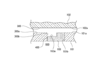
- FIG. 7 and FIG. 8 show a state when the molten resin is filled, and this figure is an enlarged cross-sectional view showing a state where the molten resin is filled in the first portion of the cavity.
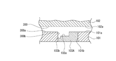
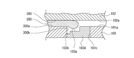
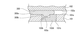
- FIG. 12 and FIG. 13 show the state when the molten resin is filled in the mold using the insert according to the first modification, and this figure shows the molten resin in the first portion of the cavity.
- FIG. 16 and FIG. 17 relate to measurement, and this figure is a cross-sectional view showing a test mold. It is a graph which shows the measurement result at the time of using a polybutylene terephthalate as molten resin. It is a graph which shows the measurement result at the time of using a polycarbonate as molten resin.
- the vehicle lamps 50 are respectively attached to the left and right ends of the front end of the vehicle body.
- the vehicle lamp 50 includes a lamp housing 51 having an opening on the front side and a cover 52 that closes the opening of the lamp housing 51.
- the lamp housing 51 and the cover 52 constitute a lamp outer casing 53, and the inner space of the lamp outer casing 53 is formed as a lamp chamber 54.
- a reflector 55 is disposed in the lamp chamber 54, and a light source 56 is attached to the reflector 55.
- a lamp extension 57 is disposed in the lamp chamber 54 on the front side of the reflector 55.
- the lamp extension 57 has a function of shielding the internal structure of the vehicular lamp 50 to improve the appearance, is formed of a resin material, and is formed as a resin molded product described later.
- a lamp unit having a lens holder or a projection lens may be disposed in the lamp chamber 54.
- the resin molded product 1 is formed by injection molding, for example, from a crystalline resin material such as polybutylene terephthalate (PBT), polyethylene terephthalate (PET), polyacetal (POM), polycarbonate (PC).
- PBT polybutylene terephthalate
- PET polyethylene terephthalate
- POM polyacetal
- PC polycarbonate
- the resin molded product 1 is used as a part of a vehicle lamp.
- the resin molded article 1 is molded as an extension for a lamp for improving the appearance by shielding the internal structure of the vehicle headlamp.
- the resin molded product 1 has a base 2 formed in a horizontally long annular shape and ribs 3, 3,... Protruding outward from the outer surface of the base 2 (see FIG. 2).
- the base 2 is partly provided with, for example, left and right side portions located on the lower side as bent portions 4 and 4, respectively, and the bent portions 4 and 4 are formed in a gently curved surface convex outward.
- the ribs 3, 3,... Protrude from the outer peripheral surfaces of the bent portions 4, 4, are formed in a shape extending in the front-rear direction, and are spaced apart in the circumferential direction of the base 2.
- the rib 3 protrudes in a direction inclined at a predetermined angle with respect to the thickness direction (H shown in FIG. 3) of the continuous portion 4 a continuous with the rib 3 in the bent portion 4.
- the inclination angle ⁇ with respect to the thickness direction H of the rib 3 is, for example, about 10 °.
- the ribs 3, 3,... Have a function of preventing deformation of the bent portions 4, 4 due to shrinkage of the molten resin described later.
- the inner peripheral surface and the front surface of the base 2 are formed as, for example, mirror-finished design surfaces 1 a and 1 a, and the design surfaces 1 a and 1 a in a state where the resin molded product 1 is disposed in the lamp chamber 54.
- the surface is visible from the outside.
- the surfaces of the ribs 3, 3,... In the resin molded product 1 are non-design surfaces 1b, 1b,.
- FIGS. 4 and 5 are vertical cross-sectional views of the mold 100 facing in the left-right direction at the position where the rib 3 is formed
- FIG. 5 is a front-back direction showing a part of the mold 100 at the position where the rib 3 is formed.
- FIG. 6 to 13 described later are also enlarged vertical sectional views at the same cutting position as FIG. 5 to 13 show an example in which one rib 3 is formed in order to facilitate understanding of the description.
- the mold 100 includes a core mold 101 used as a movable mold, a mold mold 102 used as a fixed mold, and a nesting 103.
- the core mold 101 and the mold mold 102 are provided as a base portion in the mold 100.
- the inner surfaces of the core mold 101 and the cavity mold 102 are formed as cavity forming surfaces 101 a and 102 a that form cavities 300, respectively.
- Arrangement recesses 101b, 101b,... Opened at least downward are formed at the lower end of the core mold 101.
- the inserts 103, 103,... Are inserted into the placement recesses 101b, 101b,.
- the nests 103, 103, ... are for forming the ribs 3, 3, ..., and the same number as the number of the formed ribs 3, 3, ... is provided.
- a cavity 300 filled with the molten resin 200 is formed by abutment of the core mold 101 with the inserts 103, 103,... Inserted into the placement recesses 101b, 101b,. .
- the direction of separation when the core mold 101 and the cavity mold 102 are closed or opened is, for example, the front-rear direction.
- the insert 103 is formed in a shape extending in the same direction as the direction in which the rib 3 extends (front-rear direction), and the insert 103 is formed with a filling recess 103a that opens upward and laterally (see FIG. 5). Accordingly, the nest 103 has a stepped cross section that is orthogonal to the extending direction (front-rear direction).
- the shape of the nest 103 is simple.
- a cutting blade is applied to the material for manufacturing the nest 103.
- the nest 103 can be manufactured in a stepped shape, the manufacture of the nest 103 is facilitated, and the manufacturing cost of the mold 100 is reduced. Can do.
- a certain gap 400 is formed between the insert 103 and the core mold 101.
- the gap 400 is formed on the filling recess 103a side, and one end communicates with the filling recess 103a and the other end communicates with the outside, that is, the outside 600 of the mold 100.
- the gap 400 has a width that prevents the molten resin 200 from entering, for example, a width of 0.1 mm to 0.35 mm.
- the ribs 3, 3,... That are inclined at a predetermined angle ⁇ with respect to the deformation direction B are provided. Deformation to is prevented.
- the ribs 3, 3,... Prevent the bent portions 4 and 4 from being deformed when the molten resin 200 is cooled. Sometimes, the bent portions 4 and 4 are not deformed, and the bent portions 4 and 4 are prevented from being damaged due to contact with the mold 102, and the moldability of the resin molded product 1 can be improved.
- the molten resin 200 is filled into the cavity 300 of the mold 100, first, the molten resin 200 is filled into the first portion 300a of the cavity 300 (see FIG. 6).
- the molten resin 200 is continuously filled in the first part 300a and is also filled from the first part 300a to the second part 300b (filling recess 103a of the insert 103) (see FIG. 7).
- air (residual air) existing in the filling recess 103a is pushed out from the gap 400 to the outside 600 by the molten resin 200 filled in the second portion 300b.
- the molten resin 200 is further filled into the first portion 300a and the second portion 300b, and is filled over the entire cavity 300 (see FIG. 8).
- the air present in the filling recess 103a is pushed out from the gap 400 to the outside 600 by the molten resin 200 filled in the second portion 300b, the first portion is unlikely to enter the first portion 300a. It is difficult to affect the molten resin 200 filled in 300a.
- the insert 103A is formed in a shape extending in the same direction as the direction in which the rib 3 extends (front-rear direction).
- the insert 103A has a filling recess 103a that opens upward and laterally, and an air reservoir recess 103b that continues to the filling recess 103a. Is formed.
- the air reservoir recess 103b is formed below the filling recess 103a, and the insert 103A is formed in a step shape in a cross-section perpendicular to the extending direction (front-rear direction).
- the insert 103A is formed in a staircase shape, the shape of the insert 103A is simple, the manufacture of the insert 103A becomes easy, and the manufacturing cost of the mold 100 is reduced. Can be planned.
- the gap 400 may not be formed between the insert 103A and the core mold 101 in a state where the insert 103A is inserted into the arrangement recess 101b of the core mold 101 (see FIG. 9).
- the gap between the nesting 103A and the core die 101 is inserted in the state where the nesting 103A is inserted into the arrangement recess 101b of the core die 101. 400 may be formed (see FIG. 10).
- the molten resin 200 is filled into the cavity 300 of the mold 100, first, the molten resin 200 is filled into the first portion 300a of the cavity 300 (see FIG. 11).
- the molten resin 200 is continuously filled in the first portion 300a and is also filled from the first portion 300a to the second portion 300b (filling recess 103a of the insert 103A) (see FIG. 12).
- the air present in the filling recess 103a is pushed out toward the air reservoir recess 103b by the molten resin 200 filled in the second portion 300b and stays in the air reservoir recess 103b.
- the molten resin 200 is further filled into the first portion 300a and the second portion 300b, and is filled over the entire cavity 300 (see FIG. 13).
- the air present in the filling recess 103a is pushed out into the air pool recess 103b by the molten resin 200 filled in the second portion 300b and stays in the air pool recess 103b, and therefore enters the first portion 300a. It is difficult to affect the molten resin 200 filled in the first portion 300a.
- the insert 103A when the gap 400 is formed (see FIG. 10), the air existing in the filling recess 103a is retained by the molten resin 200 filled in the second portion 300b. It is pushed out into the recess 103b and pushed out from the gap 400 to the outside 600. Therefore, the air present in the filling recess 103a is less likely to enter the first portion 300a, and the molten resin 200 filled in the first portion 300a is less likely to be affected.
- the nest 103B is inserted into the arrangement recess 101b of the core mold 101 and arranged, and the first molded part 104, the second molded part 105, and the third molded part 106 formed in the same step-like shape are arranged in the horizontal direction. And are integrally formed continuously.
- filling concave portions 103a, 103a, and 103a are formed in the first molding portion 104, the second molding portion 105, and the third molding portion 106, respectively.
- a certain gap 400 is formed between the first molding portion 104 of the insert 103 and the core mold 101.
- a gap (through hole) 400 is formed between the first molded part 104 and the second molded part 105, and an air reservoir recess 103 b is formed between the second molded part 105 and the third molded part 106.
- the ribs 3, 3, and 3 are formed by filling the filling recesses 103a, 103a, and 103a with the molten resin 200.
- the air existing in the filling recesses 103a, 103a, 103a is pushed out from the gaps 400, 400 to the outside 600 by the molten resin 200 and pushed out toward the air pool recess 103b. As a result, the air stays in the recess 103b.
- the air present in the filling recesses 103a, 103a, 103a is pushed out from the gaps 400, 400 to the outside 600 by the molten resin 200 and is pushed out into the air pool recess 103b and stays in the air pool recess 103b. It is difficult for the first portion 300a to enter and the molten resin 200 filled in the first portion 300a is hardly affected.
- the insert 103B has three filling recesses 103a, 103a, and 103a for forming the ribs 3, 3, and 3, the number of parts of the mold 100 can be reduced by using the insert 103B. The manufacturing cost of the mold 100 can be reduced.
- the number of the filling recessed parts 103a of the nest 103B is arbitrary, and the filling recessed part 103a is the number of the ribs 3 to shape
- the number and positions of the gaps 400 and the air reservoir recesses 103b are arbitrary, and only the gaps 400, 400,... May be formed in the nest 103B, and only the air reservoir recesses 103b, 103b,. Further, the gap 400 and the air reservoir recess 103b may be formed at arbitrary positions one by one.
- FIG. 15 is a vertical cross-sectional view of the test mold 100X facing in the left-right direction at the position where the rib 3 is formed. Further, FIG. 15 exaggerates the portion where the rib 3 is formed for convenience of explanation, and shows the ratio of the vertical and horizontal heights in a state different from the actual one.
- the mold 100X has a core mold 101X, a cavity mold 102X, and a nesting 103X.
- the insert 103X has a filling recess 103a and an air reservoir recess 103b in the same manner as the insert 103A according to the first modification. Between the insert 103X and the core mold 101, a constant gap 400 and a gap 500 are formed on both sides of the insert 103X.
- the temperature of the molten resin 200 in the measurement was 250 ° C., and the temperature of the mold 100X was 50 ° C.
- the widths H and H of the gaps 400 and 500 were set to 0.01 mm to 0.04 mm, respectively, and the formed rib 3 (filled recess 103a) had a height A of 2 mm and a width B of 0.8 mm. Further, the air reservoir recess 103b was measured by changing the height C and the width D, respectively.
- FIG. 16 shows a measurement result when polybutylene terephthalate (PBT) is used as the molten resin 200
- FIG. 17 shows a measurement result when polycarbonate (PC) is used as the molten resin 200.
- PBT polybutylene terephthalate
- PC polycarbonate
- ⁇ is an example in which degassed silver and weld lines were not recognized
- ⁇ was a case in which at least one of degassed silver or weld lines was slightly recognized, but in terms of appearance as a product.
- x is an example in which at least one of degassed silver or weld line is recognized and it is determined that the product has an appearance problem.
- the crystalline resin material is an amorphous resin material. Since the fluidity at the time of melting is higher than that of the mold 100, the transferability to the molding surface of the mold 100 is high, and the air bubbles present on the molding surface are easily scattered from the molding surface. It becomes easy to be pushed out toward the part.
- PBT polybutylene terephthalate
- PET polyethylene terephthalate
- POM polyacetal
- the use of the insert 103, the insert 103 ⁇ / b> A or the insert 103 ⁇ / b> B as described above improves the moldability of the resin molded product 1. Above all, a particularly great effect is exhibited with respect to preventing the appearance defect of the resin molded product 1.
- a gap 400 is formed between the core mold 101 and the insert 103A, so that air existing in the filling recess 103a is pushed out to the air reservoir recess 103b or from the gap 400 to the outside 600. Since it is extruded, it is possible to prevent further appearance defects of the resin molded product 1 while improving the moldability of the resin molded product 1.
- the resin molded product 1 molded by the mold 100 is molded in a state in which the air present in the filling recess 103a hardly affects the molten resin 200 filled in the first portion 300a, the moldability of the resin molded product 1 is improved. After improving, it is molded as a good product in which appearance defects are prevented.
- the surface of rib 3, 3, ... is formed as the non-design surface 1b. Because of the surface, when degassed silver is generated in the ribs 3, 3,..., The resin molded product 1 is molded as a good product without causing a problem in appearance.
Landscapes
- Engineering & Computer Science (AREA)
- Manufacturing & Machinery (AREA)
- Mechanical Engineering (AREA)
- General Engineering & Computer Science (AREA)
- Moulds For Moulding Plastics Or The Like (AREA)
- Non-Portable Lighting Devices Or Systems Thereof (AREA)
Abstract
成形性の向上を図った上で外観不良を防止する。 キャビティ300に充填される溶融樹脂200を基部2と基部から突出されたリブ3とを有する樹脂成形品1として形成するための金型100において、ベース部とリブを形成するための溶融樹脂200が充填される充填凹部103aを有する入れ子103とを備え、外部600と前記充填凹部に連通され溶融樹脂の侵入が不能とされた隙間400が形成された。これにより、充填凹部に存在していた空気が充填凹部に充填される溶融樹脂以外の溶融樹脂に吹き付けられ難いため、成形性の向上を図った上で外観不良を防止することができる。
Description
本発明は、キャビティに充填される溶融樹脂を基部と基部から突出されたリブとを有する樹脂成形品として形成するための金型及びこれにより成形される灯具用エクステンションの技術分野に関する。
車輌用灯具の部品として用いられる車輌用灯具部品には、例えば、光源が配置されるランプハウジング、光源から出射された光を反射するリフレクター、内部構造を遮蔽して見栄えの向上を図るための灯具用エクステンション等の各種のものがある。
このような車輌用灯具部品には、コア型とキャビ型を有する金型のキャビティに充填された溶融樹脂が冷却されて樹脂成形品として成形されるものがある(例えば、特許文献1参照)。
特許文献1には、リフレクターや灯具用エクステンション等の車輌用灯具部品がポリブチレンテレフタレート(PBT)等の樹脂材料によって成形される技術が開示されている。
ところで、上記のような樹脂成形品として成形される車輌用灯具部品は、金型のキャビティに充填された溶融樹脂が冷却されることにより成形されるため、冷却時に収縮が生じ易い。特に、樹脂材料としてポリブチレンテレフタレート等の結晶性樹脂材料が用いられた場合には、冷却時に大きな収縮が生じるおそれがある。
一方、車輌用灯具部品は各種の機能を有し様々な形状に形成されるため、一部が所定の方向へ屈曲された屈曲部として設けられていることが多い。
従って、溶融樹脂の冷却時に収縮が生じると、収縮によって屈曲部に曲率半径が大きくなる方向への力が生じてしまい、金型の離型時に車輌用灯具部品が金型に擦ってしまい、車輌用灯具部品が傷付いて成形性が低下するおそれがある。
そこで、金型に成形用凹部を形成し、成形用凹部によって冷却時における収縮に起因する屈曲部の変形方向に対して傾斜されるリブが車輌用灯具部品に成形されるようにし、リブによって溶融樹脂の冷却時における屈曲部の変形を防止して屈曲部の金型との接触による傷付きを防止することが考えられる。
ところが、成形用凹部を有する金型を用いて車輌用灯具部品を成形する場合には、金型のキャビティへの溶融樹脂の充填時に、キャビティに存在する空気の一部が溶融樹脂によって成形用凹部に一時的に残留エアーとして閉じ込められ、残留エアーが成形用凹部に充填される溶融樹脂によって押し出されたときに成形用凹部以外の部分に充填される溶融樹脂の表面に残留エアーが吹き付けられてしまう。
成形用凹部以外の部分に充填される溶融樹脂に残留エアーが吹き付けられてしまうと、残留エアーの作用によって溶融樹脂の表面が荒らされて所謂脱気シルバーが生じ、脱気シルバーによって車輌用灯具部品における外観不良が生じるおそれがある。
そこで、本発明金型及び灯具用エクステンションは、上記した問題点を克服し、成形性の向上を図った上で外観不良を防止することを課題とする。
本発明に係る金型は、上記した課題を解決するために、キャビティに充填される溶融樹脂を基部と前記基部から突出されたリブとを有する樹脂成形品として形成するための金型であって、ベース部と前記リブを形成するための溶融樹脂が充填される充填凹部を有する入れ子とを備え、外部と前記充填凹部に連通され前記溶融樹脂の侵入が不能とされた隙間が形成されたものである。
これにより、隙間から充填凹部に存在していた空気が外部へ流出される。
第2に、上記した本発明に係る金型においては、前記入れ子が階段形状に形成されることが望ましい。
これにより、入れ子の形状が簡素になる。
別の本発明に係る金型は、上記した課題を解決するために、キャビティに充填される溶融樹脂を基部と前記基部から突出されたリブとを有する樹脂成形品として形成するための金型であって、ベース部と前記リブを形成するための溶融樹脂が充填される充填凹部を有する入れ子とを備え、前記入れ子に、前記充填凹部に連通された空気溜まり凹部が形成されたものである。
これにより、充填凹部に存在していた空気が空気溜まり凹部に滞留される。
第4に、上記した別の本発明に係る金型においては、前記ベース部と前記入れ子の間に、外部及び前記空気溜まり凹部に連通され前記溶融樹脂の侵入が不能とされた隙間が形成されることが望ましい。
これにより、充填凹部に存在する空気が溶融樹脂よって空気溜まり凹部へ押し出されると共に隙間から外部へ押し出される。
第5に、上記した別の本発明に係る金型においては、前記空気溜まり凹部が前記入れ子の一端部に形成されて前記入れ子が階段形状に形成されることが望ましい。
これにより、入れ子の形状が簡素になる。
本発明に係る灯具用エクステンションは、上記した課題を解決するために、基部と前記基部から突出されたリブとを有し金型のキャビティに充填された溶融樹脂が冷却されて形成される灯具用エクステンションであって、前記金型はベース部と前記溶融樹脂の一部が充填される充填凹部を有する入れ子とを備え、外部と前記充填凹部に連通され前記溶融樹脂の侵入が不能とされた隙間が形成され、少なくとも前記充填凹部に充填された溶融樹脂によって前記リブが形成されるものである。
これにより、隙間から充填凹部に存在していた空気が外部へ流出される金型によって成形される。
別の本発明に係る灯具用エクステンションは、上記した課題を解決するために、基部と前記基部から突出されたリブとを有し金型のキャビティに充填された溶融樹脂が冷却されて形成される灯具用エクステンションであって、前記金型はベース部と前記溶融樹脂の一部が充填される充填凹部を有する入れ子とを備え、前記入れ子に、前記充填凹部に連通された空気溜まり凹部が形成され、少なくとも前記充填凹部に充填された溶融樹脂によって前記リブが形成されるものである。
これにより、充填凹部に存在していた空気が空気溜まり凹部に滞留される金型によって成形される。
本発明によれば、充填凹部に存在していた空気が充填凹部に充填される溶融樹脂以外の溶融樹脂に吹き付けられ難いため、成形性の向上を図った上で外観不良を防止することができる。
以下に、本発明を実施するための形態について添付図面を参照して説明する。
<車輌用灯具の概略構成>
先ず、樹脂成形品が設けられる車輌用灯具の概略構成について説明する(図1参照)。
先ず、樹脂成形品が設けられる車輌用灯具の概略構成について説明する(図1参照)。
車輌用灯具50は、例えば、それぞれ車体の前端部における左右両端部に取り付けられて配置されている。
車輌用灯具50は前方に開口を有するランプハウジング51とランプハウジング51の開口を閉塞するカバー52とを備えている。ランプハウジング51とカバー52によって灯具外筐53が構成され、灯具外筐53の内部空間が灯室54として形成されている。
灯室54にはリフレクター55が配置され、リフレクター55には光源56が取り付けられている。灯室54にはリフレクター55の前側に灯具用エクステンション57が配置されている。灯具用エクステンション57は車輌用灯具50の内部構造を遮蔽して見栄えの向上を図る機能を有し、樹脂材料によって形成され、後述する樹脂成形品として成形されている。
尚、車輌用灯具50にあっては、灯室54にレンズホルダーや投影レンズを有するランプユニットが配置されていてもよい。
<樹脂成形品(車輌用灯具部品)の構成>
次に、金型によって車輌用灯具部品である灯具用エクステンション57として成形される樹脂成形品1の構成について説明する(図2及び図3参照)。
次に、金型によって車輌用灯具部品である灯具用エクステンション57として成形される樹脂成形品1の構成について説明する(図2及び図3参照)。
樹脂成形品1は射出成形によって、例えば、ポリブチレンテレフタレート(PBT)、ポリエチレンテレフタレート(PET)、ポリアセタール(POM)、ポリカーボネート(PC)等の結晶性樹脂材料により成形されている。樹脂成形品1は車輌用灯具の部品として用いられ、例えば、車輌用前照灯の内部構造を遮蔽して見栄えの向上を図るための灯具用エクステンションとして成形されている。
樹脂成形品1は横長の環状に形成された基部2と基部2の外面から外方へ突出されたリブ3、3、・・・とを有している(図2参照)。
基部2は一部、例えば、下方側に位置する左右両側の部分がそれぞれ屈曲部4、4として設けられ、屈曲部4、4は外方へ凸の緩やかな曲面状に形成されている。
リブ3、3、・・・はそれぞれ屈曲部4、4の外周面から突出され、前後に延びる形状に形成され、基部2の周方向に離隔して位置されている。リブ3は、屈曲部4のうちリブ3と連続する連続部分4aの厚み方向(図3に示すH)に対して所定の角度傾斜する方向へ突出されている。
リブ3の厚み方向Hに対する傾斜角度θは、例えば、10°程度にされている。リブ3、3、・・・は、後述する溶融樹脂の収縮に起因する屈曲部4、4の変形を防止する機能を有している。
樹脂成形品1は少なくとも基部2の内周面と前面が、例えば、鏡面にされた意匠面1a、1aとして形成され、樹脂成形品1が灯室54に配置された状態において意匠面1a、1aが外部から視認可能な面とされている。また、樹脂成形品1のうちリブ3、3、・・・の表面は外部から視認不能な非意匠面1b、1b、・・・とされている。
<金型の構造>
次に、樹脂成形品1を射出成形によって成形する金型100について説明する(図4及び図5参照)。図4は、リブ3が形成される位置における金型100の左右方向を向く状態の垂直断面図であり、図5は、リブ3が形成される位置における金型100の一部を示す前後方向を向く状態の拡大垂直断面図である。尚、後述する図6乃至図13も図5と同様の切断位置における拡大垂直断面図である。また、図5乃至図13は、説明の理解を容易にするために、一つのリブ3が形成される例を示している。
次に、樹脂成形品1を射出成形によって成形する金型100について説明する(図4及び図5参照)。図4は、リブ3が形成される位置における金型100の左右方向を向く状態の垂直断面図であり、図5は、リブ3が形成される位置における金型100の一部を示す前後方向を向く状態の拡大垂直断面図である。尚、後述する図6乃至図13も図5と同様の切断位置における拡大垂直断面図である。また、図5乃至図13は、説明の理解を容易にするために、一つのリブ3が形成される例を示している。
金型100は可動型として用いられたコア型101と固定型として用いられたキャビ型102と入れ子103とを有している。コア型101とキャビ型102は金型100におけるベース部として設けられている。コア型101とキャビ型102の各内面はそれぞれキャビティ300を形成するキャビティ形成面101a、102aとして形成されている。
コア型101の下端部には少なくとも下方に開口された配置凹部101b、101b、・・・が形成されている。配置凹部101b、101b、・・・にはそれぞれ入れ子103、103、・・・が挿入されて配置される。入れ子103、103、・・・はリブ3、3、・・・を形成するためのものであり、形成されるリブ3、3、・・・の数と同数が設けられている。
配置凹部101b、101b、・・・にそれぞれ入れ子103、103、・・・が挿入されたコア型101とキャビ型102が突き合わされることにより、溶融樹脂200が充填されるキャビティ300が形成される。金型100にあっては、コア型101とキャビ型102の型閉め時又は型開き時の離接方向が、例えば、前後方向とされている。
入れ子103はリブ3が延びる方向(前後方向)と同じ方向に延びる形状に形成され、入れ子103には上方及び側方に開口された充填凹部103aが形成されている(図5参照)。従って、入れ子103は延びる方向(前後方向)に対して直交する断面形状が階段形状に形成されている。
このように金型100にあっては、入れ子103が階段形状に形成されているため、入れ子103の形状が簡素であり、例えば、入れ子103を製造するための材料に対して切削用の刃物を鉛直方向及び水平方向において一方から他方へ移動させることにより入れ子103を階段状の形状に製造することが可能であり、入れ子103の製造が容易になり、金型100の製造コストの低減を図ることができる。
コア型101の配置凹部101bに入れ子103が挿入された状態において、入れ子103とコア型101の間に一定の隙間400が形成される。隙間400は充填凹部103a側に形成され、一端が充填凹部103aに連通され他端が外部、即ち、金型100の外部600に連通される。隙間400は溶融樹脂200の侵入が不能な幅とされ、例えば、幅が0.1mm乃至0.35mmとされている。
上記したように、配置凹部101b、101b、・・・にそれぞれ入れ子103、103、・・・が挿入されたコア型101とキャビ型102が突き合わされることにより、溶融樹脂200が充填されるキャビティ300が形成されるが、キャビティ300は基部2を成形するための環状に形成された第1の部分300aとリブ3、3、・・・をそれぞれ成形するための第2の部分300b、300b、・・・とによって構成される。第2の部分300b、300b、・・・はそれぞれ入れ子103、103、・・・の充填凹部103a、103a、・・・に相当する部分である。
<金型による樹脂成形品の成形>
金型100のキャビティ300に溶融樹脂200が充填されて冷却されると、冷却時に溶融樹脂200に収縮力が生じ、基部2においては、収縮力が、特に、周方向(図2及び図3に示すA方向)において大きい。このようなA方向への収縮力が生じると、収縮力に起因して屈曲部4、4に曲率半径が大きくなる方向(図3に示すB方向)への変形力が生じる。B方向(変形方向)はリブ3の厚み方向に一致する。
金型100のキャビティ300に溶融樹脂200が充填されて冷却されると、冷却時に溶融樹脂200に収縮力が生じ、基部2においては、収縮力が、特に、周方向(図2及び図3に示すA方向)において大きい。このようなA方向への収縮力が生じると、収縮力に起因して屈曲部4、4に曲率半径が大きくなる方向(図3に示すB方向)への変形力が生じる。B方向(変形方向)はリブ3の厚み方向に一致する。
ところが、樹脂成形品1においては、変形方向Bに対して所定の角度θ傾斜するリブ3、3、・・・が設けられているため、収縮力に起因する屈曲部4、4の変形方向Bへの変形が防止される。
従って、樹脂成形品1にあっては、リブ3、3、・・・によって溶融樹脂200の冷却時における屈曲部4、4の変形が防止されるため、コア型101とキャビ型102の型開き時に屈曲部4、4が変形されず屈曲部4、4のキャビ型102との接触による傷付きが防止され、樹脂成形品1の成形性の向上を図ることができる。
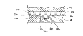
金型100のキャビティ300に溶融樹脂200が充填されるときには、先ず、溶融樹脂200がキャビティ300の第1の部分300aに充填されていく(図6参照)。溶融樹脂200は引き続いて第1の部分300aに充填されていくと共に第1の部分300aから第2の部分300b(入れ子103の充填凹部103a)にも充填される(図7参照)。このとき充填凹部103aに存在する空気(残留エアー)が第2の部分300bに充填される溶融樹脂200によって隙間400から外部600へ押し出されていく。溶融樹脂200はさらに第1の部分300a及び第2の部分300bに充填されていき、キャビティ300の全体に亘って充填される(図8参照)。
このように充填凹部103aに存在する空気は、第2の部分300bに充填される溶融樹脂200によって隙間400から外部600へ押し出されていくため、第1の部分300aに侵入し難く第1の部分300aに充填される溶融樹脂200に影響を及ぼし難い。
<入れ子の第1の変形例>
以下に、第1の変形例に係る入れ子103Aについて説明する(図9乃至図13参照)。
以下に、第1の変形例に係る入れ子103Aについて説明する(図9乃至図13参照)。
入れ子103Aはリブ3が延びる方向(前後方向)と同じ方向に延びる形状に形成され、入れ子103Aには上方及び側方に開口された充填凹部103aと充填凹部103aに連続する空気溜まり凹部103bとが形成されている。空気溜まり凹部103bは充填凹部103aより下側に形成され、入れ子103Aは延びる方向(前後方向)に対して直交する断面形状が階段形状に形成されている。
このように金型100にあっては、入れ子103Aが階段形状に形成されているため、入れ子103Aの形状が簡素であり、入れ子103Aの製造が容易になり、金型100の製造コストの低減を図ることができる。
尚、入れ子103Aが用いられた場合には、コア型101の配置凹部101bに入れ子103Aが挿入された状態において、入れ子103Aとコア型101の間に隙間400が形成されていなくてもよい(図9参照)。
但し、入れ子103Aが用いられた場合においても、入れ子103が用いられた場合と同様に、コア型101の配置凹部101bに入れ子103Aが挿入された状態において、入れ子103Aとコア型101の間に隙間400が形成されていてもよい(図10参照)。
入れ子103Aが用いられた場合において、金型100のキャビティ300に溶融樹脂200が充填されるときには、先ず、溶融樹脂200がキャビティ300の第1の部分300aに充填されていく(図11参照)。溶融樹脂200は引き続いて第1の部分300aに充填されていくと共に第1の部分300aから第2の部分300b(入れ子103Aの充填凹部103a)にも充填される(図12参照)。このとき充填凹部103aに存在する空気が第2の部分300bに充填される溶融樹脂200によって空気溜まり凹部103bへ向けて押し出されて空気溜まり凹部103bに滞留されていく。溶融樹脂200はさらに第1の部分300a及び第2の部分300bに充填されていき、キャビティ300の全体に亘って充填される(図13参照)。
このように充填凹部103aに存在する空気は、第2の部分300bに充填される溶融樹脂200によって空気溜まり凹部103bへ押し出されて空気溜まり凹部103bに滞留されるため、第1の部分300aに侵入し難く第1の部分300aに充填される溶融樹脂200に影響を及ぼし難い。
尚、入れ子103Aが用いられた場合において、隙間400が形成されているとき(図10参照)には、充填凹部103aに存在する空気が第2の部分300bに充填される溶融樹脂200によって空気溜まり凹部103bへ押し出されていくと共に隙間400から外部600へ押し出されていく。従って、充填凹部103aに存在する空気が第1の部分300aに一層侵入し難く第1の部分300aに充填される溶融樹脂200に一層影響を及ぼし難くなる。
<入れ子の第2の変形例>
以下に、第2の変形例に係る入れ子103Bについて説明する(図14参照)。
以下に、第2の変形例に係る入れ子103Bについて説明する(図14参照)。
入れ子103Bはコア型101の配置凹部101bに挿入されて配置され、階段状の同様の形状に形成された第1の成形部104と第2の成形部105と第3の成形部106が左右方向において連続して一体に形成されて成る。入れ子103Bには、第1の成形部104と第2の成形部105と第3の成形部106に、それぞれ充填凹部103a、103a、103aが形成されている。
コア型101の配置凹部101bに入れ子103Bが挿入された状態において、入れ子103の第1の成形部104とコア型101の間に一定の隙間400が形成される。第1の成形部104と第2の成形部105の間には隙間(貫通孔)400が形成され、第2の成形部105と第3の成形部106の間には空気溜まり凹部103bが形成されている。
入れ子103Bが用いられた金型100において、充填凹部103a、103a、103aに溶融樹脂200が充填されることによりリブ3、3、3が成形される。溶融樹脂200がキャビティ300に充填されていくときには、充填凹部103a、103a、103aに存在する空気が溶融樹脂200によって隙間400、400から外部600へ押し出されていくと共に空気溜まり凹部103bへ向けて押し出されて空気溜まり凹部103bに滞留されていく。
このように充填凹部103a、103a、103aに存在する空気は、溶融樹脂200によって隙間400、400から外部600へ押し出されていくと共に空気溜まり凹部103bへ押し出されて空気溜まり凹部103bに滞留されるため、第1の部分300aに侵入し難く第1の部分300aに充填される溶融樹脂200に影響を及ぼし難い。
また、入れ子103Bはリブ3、3、3を成形するための三つの充填凹部103a、103a、103aを有しているため、入れ子103Bを用いることにより金型100の部品点数を低減することができ、金型100の製造コストの低減を図ることができる。
尚、上記には、三つの充填凹部103a、103a、103aを有する入れ子103Bの例を示したが、入れ子103Bの充填凹部103aの数は任意であり、充填凹部103aは成形するリブ3の数に応じた数が形成されていればよい。また、隙間400と空気溜まり凹部103bの数及び位置も任意であり、入れ子103Bには隙間400、400、・・・のみが形成されていてもよく、空気溜まり凹部103b、103b、・・・のみが形成されていてもよく、また、隙間400と空気溜まり凹部103bがそれぞれ少なくとも一つずつ任意の位置に形成されていてもよい。
<隙間の効果測定>
金型100にあっては、上記したように、充填凹部103aに存在する空気が第2の部分300bに充填される溶融樹脂200によって押し出されていくため、第1の部分300aに侵入し難いが、万が一、充填凹部103aに存在する空気が第1の部分300aに侵入すると、第1の部分300aに充填される溶融樹脂200の表面が侵入する空気によって荒らされて脱気シルバーが生じるおそれがある。
金型100にあっては、上記したように、充填凹部103aに存在する空気が第2の部分300bに充填される溶融樹脂200によって押し出されていくため、第1の部分300aに侵入し難いが、万が一、充填凹部103aに存在する空気が第1の部分300aに侵入すると、第1の部分300aに充填される溶融樹脂200の表面が侵入する空気によって荒らされて脱気シルバーが生じるおそれがある。
そこで、空気溜まり凹部103bの幅や高さを変更して、金型100による効果を確認するための測定を以下のようにしてテスト用の金型100Xを用いて行った(図15乃至図17参照)。尚、図15は、リブ3が形成される位置におけるテスト用の金型100Xの左右方向を向く状態の垂直断面図である。また、図15は、説明の都合上、リブ3が形成される部分を誇張して示しており、縦横高さの比を実際のものとは異なる状態で示している。
金型100Xはコア型101Xとキャビ型102Xと入れ子103Xを有している。入れ子103Xは第1の変形例に係る入れ子103Aと同様に充填凹部103aと空気溜まり凹部103bを有している。入れ子103Xとコア型101の間には、入れ子103Xの両側にそれぞれ一定の隙間400と隙間500が形成される。
測定における溶融樹脂200の温度は250°Cとし、金型100Xの温度は50°Cとした。隙間400、500の幅H、Hはそれぞれ0.01mm乃至0.04mmとし、形成されるリブ3(充填凹部103a)は高さAを2mmとし幅Bを0.8mmとした。また、空気溜まり凹部103bは高さCと幅Dをそれぞれ変更して測定を行った。
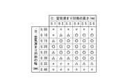
図16は、溶融樹脂200としてポリブチレンテレフタレート(PBT)を用いた場合の測定結果を示し、図17は、溶融樹脂200としてポリカーボネート(PC)を用いた場合の測定結果を示している。図16及び図17において、「○」は脱気シルバーとウエルドラインが認められなかった例であり、「△」は脱気シルバー又はウエルドラインの少なくとも一方が若干認められたが製品としての外観上問題がない例であり、「×」は脱気シルバー又はウエルドラインの少なくとも一方が認められ製品として外観上支障を来すと判断された例である。
図16に示すように、溶融樹脂200としてポリブチレンテレフタレート(PBT)を用いた場合には、空気溜まり凹部103bの高さが0.1mm乃至0.6mmにおいて一部を除いて良好な結果が得られ、空気溜まり凹部103bの幅が0.10mm乃至0.35mmにおいて一部を除いて良好な結果が得られた。特に、空気溜まり凹部103bの高さが0.1mm乃至0.6mmかつ空気溜まり凹部103bの幅が0.15mm乃至0.30mmにおいて良好な結果が得られた。
また、図17に示すように、溶融樹脂200としてポリカーボネート(PC)を用いた場合には、空気溜まり凹部103bの高さが0.1mm乃至1.0mmにおいて一部を除いて良好な結果が得られ、空気溜まり凹部103bの幅が0.10mm乃至0.90mmにおいて一部を除いて良好な結果が得られた。特に、空気溜まり凹部103bの高さが0.1mm乃至1.0mmかつ空気溜まり凹部103bの幅が0.20mm乃至0.70mmにおいて良好な結果が得られた。
<まとめ>
以上に記載した通り、金型100にあっては、入れ子103が用いられた場合には充填凹部103aに存在する空気が隙間400から外部600へ押し出され、入れ子103Aが用いられた場合には充填凹部103aに存在する空気が空気溜まり凹部103bへ押し出されて空気溜まり凹部103bに滞留され又は隙間400から外部600へ押し出される。また、入れ子103Bが用いられた場合には充填凹部103a、103aに存在する空気が隙間400、400から外部600へ押し出されていくと共に充填凹部103aに存在する空気が空気溜まり凹部103bへ押し出されて空気溜まり凹部103bに滞留される。
以上に記載した通り、金型100にあっては、入れ子103が用いられた場合には充填凹部103aに存在する空気が隙間400から外部600へ押し出され、入れ子103Aが用いられた場合には充填凹部103aに存在する空気が空気溜まり凹部103bへ押し出されて空気溜まり凹部103bに滞留され又は隙間400から外部600へ押し出される。また、入れ子103Bが用いられた場合には充填凹部103a、103aに存在する空気が隙間400、400から外部600へ押し出されていくと共に充填凹部103aに存在する空気が空気溜まり凹部103bへ押し出されて空気溜まり凹部103bに滞留される。
従って、溶融樹脂200の収縮力に起因する屈曲部4、4の変形がリブ3、3、・・・によって防止されることによる樹脂成形品1の成形性の向上を図った上で樹脂成形品1の外観不良を防止することができる。
特に、樹脂成形品1の材料としてポリブチレンテレフタレート(PBT)、ポリエチレンテレフタレート(PET)、ポリアセタール(POM)等の結晶性樹脂材料が用いられた場合には、結晶性樹脂材料が非結晶性樹脂材料に比し溶融時における流動性が高いため、金型100の成形面に対する転写性が高く成形面に存在する気泡を成形面から飛散させ易く、充填凹部103aに存在する空気が充填凹部103aから他の部分へ向けて押し出され易くなる。
従って、樹脂成形品1の材料として結晶性樹脂材料が用いられた場合に、上記のように、入れ子103、入れ子103A又は入れ子103Bを用いることは、樹脂成形品1の成形性の向上を図った上で樹脂成形品1の外観不良を防止することに関して特に大きな効果が発揮される。
また、入れ子103Aが用いられた場合においてコア型101と入れ子103Aの間に隙間400が形成されることにより、充填凹部103aに存在する空気が空気溜まり凹部103bへ押し出され又は隙間400から外部600へ押し出されていくため、樹脂成形品1の成形性の向上を図った上で樹脂成形品1の一層の外観不良を防止することができる。
さらに、金型100によって成形された樹脂成形品1は、充填凹部103aに存在する空気が第1の部分300aに充填される溶融樹脂200に影響を及ぼし難い状態で成形されるため、成形性の向上を図った上で外観不良が防止された良好な製品として成形される。
尚、充填凹部103aに存在する空気によってリブ3、3、・・・に脱気シルバーが発生する可能性があるが、リブ3、3、・・・の表面は非意匠面1bとして形成される面であるため、リブ3、3、・・・に脱気シルバーが発生した場合においては樹脂成形品1として外観上問題にならず、良好な製品として成形される。
57…灯具用エクステンション、1…樹脂成形品、2…基部、3…リブ、100…金型、101…コア型(ベース部)、102…キャビ型(ベース部)、103…入れ子、103a…充填凹部、200…溶融樹脂、300…キャビティ、400…隙間、103A…入れ子、103b…空気溜まり凹部、103B…入れ子
Claims (7)
- キャビティに充填される溶融樹脂を基部と前記基部から突出されたリブとを有する樹脂成形品として形成するための金型であって、
ベース部と前記リブを形成するための溶融樹脂が充填される充填凹部を有する入れ子とを備え、
外部と前記充填凹部に連通され前記溶融樹脂の侵入が不能とされた隙間が形成された
金型。 - 前記入れ子が階段形状に形成された
請求項1に記載の金型。 - キャビティに充填される溶融樹脂を基部と前記基部から突出されたリブとを有する樹脂成形品として形成するための金型であって、
ベース部と前記リブを形成するための溶融樹脂が充填される充填凹部を有する入れ子とを備え、
前記入れ子に、前記充填凹部に連通された空気溜まり凹部が形成された
金型。 - 前記ベース部と前記入れ子の間に、外部及び前記空気溜まり凹部に連通され前記溶融樹脂の侵入が不能とされた隙間が形成された
請求項3に記載の金型。 - 前記空気溜まり凹部が前記入れ子の一端部に形成されて前記入れ子が階段形状に形成された
請求項3又は請求項4に記載の金型。 - 基部と前記基部から突出されたリブとを有し金型のキャビティに充填された溶融樹脂が冷却されて形成される灯具用エクステンションであって、
前記金型はベース部と前記溶融樹脂の一部が充填される充填凹部を有する入れ子とを備え、外部と前記充填凹部に連通され前記溶融樹脂の侵入が不能とされた隙間が形成され、
少なくとも前記充填凹部に充填された溶融樹脂によって前記リブが形成される
灯具用エクステンション。 - 基部と前記基部から突出されたリブとを有し金型のキャビティに充填された溶融樹脂が冷却されて形成される灯具用エクステンションであって、
前記金型はベース部と前記溶融樹脂の一部が充填される充填凹部を有する入れ子とを備え、前記入れ子に、前記充填凹部に連通された空気溜まり凹部が形成され、
少なくとも前記充填凹部に充填された溶融樹脂によって前記リブが形成される
灯具用エクステンション。
Priority Applications (1)
| Application Number | Priority Date | Filing Date | Title |
|---|---|---|---|
| JP2016531299A JP6602296B2 (ja) | 2014-07-03 | 2015-06-24 | 金型 |
Applications Claiming Priority (2)
| Application Number | Priority Date | Filing Date | Title |
|---|---|---|---|
| JP2014-137668 | 2014-07-03 | ||
| JP2014137668 | 2014-07-03 |
Publications (1)
| Publication Number | Publication Date |
|---|---|
| WO2016002601A1 true WO2016002601A1 (ja) | 2016-01-07 |
Family
ID=55019143
Family Applications (1)
| Application Number | Title | Priority Date | Filing Date |
|---|---|---|---|
| PCT/JP2015/068225 Ceased WO2016002601A1 (ja) | 2014-07-03 | 2015-06-24 | 金型及び灯具用エクステンション |
Country Status (2)
| Country | Link |
|---|---|
| JP (1) | JP6602296B2 (ja) |
| WO (1) | WO2016002601A1 (ja) |
Cited By (1)
| Publication number | Priority date | Publication date | Assignee | Title |
|---|---|---|---|---|
| CN111351003A (zh) * | 2020-03-20 | 2020-06-30 | 华域视觉科技(上海)有限公司 | 灯罩、灯具和灯罩成型方法 |
Families Citing this family (1)
| Publication number | Priority date | Publication date | Assignee | Title |
|---|---|---|---|---|
| JP7789131B1 (ja) * | 2024-06-24 | 2025-12-19 | 森六株式会社 | 樹脂成形品 |
Citations (4)
| Publication number | Priority date | Publication date | Assignee | Title |
|---|---|---|---|---|
| JPS6171419U (ja) * | 1984-10-16 | 1986-05-15 | ||
| JP2012193661A (ja) * | 2011-03-16 | 2012-10-11 | Aisan Industry Co Ltd | デリバリパイプの成形型 |
| JP2012223989A (ja) * | 2011-04-20 | 2012-11-15 | Isuzu Motors Ltd | 射出成形方法及びこれに用いる射出成形用金型 |
| JP2014011369A (ja) * | 2012-07-02 | 2014-01-20 | Hitachi Ltd | 半導体装置及びそれを用いた電力変換装置 |
Family Cites Families (1)
| Publication number | Priority date | Publication date | Assignee | Title |
|---|---|---|---|---|
| JP6101478B2 (ja) * | 2012-12-11 | 2017-03-22 | 株式会社小糸製作所 | 樹脂成形品及び車輌用灯具部品 |
-
2015
- 2015-06-24 JP JP2016531299A patent/JP6602296B2/ja active Active
- 2015-06-24 WO PCT/JP2015/068225 patent/WO2016002601A1/ja not_active Ceased
Patent Citations (4)
| Publication number | Priority date | Publication date | Assignee | Title |
|---|---|---|---|---|
| JPS6171419U (ja) * | 1984-10-16 | 1986-05-15 | ||
| JP2012193661A (ja) * | 2011-03-16 | 2012-10-11 | Aisan Industry Co Ltd | デリバリパイプの成形型 |
| JP2012223989A (ja) * | 2011-04-20 | 2012-11-15 | Isuzu Motors Ltd | 射出成形方法及びこれに用いる射出成形用金型 |
| JP2014011369A (ja) * | 2012-07-02 | 2014-01-20 | Hitachi Ltd | 半導体装置及びそれを用いた電力変換装置 |
Cited By (2)
| Publication number | Priority date | Publication date | Assignee | Title |
|---|---|---|---|---|
| CN111351003A (zh) * | 2020-03-20 | 2020-06-30 | 华域视觉科技(上海)有限公司 | 灯罩、灯具和灯罩成型方法 |
| CN111351003B (zh) * | 2020-03-20 | 2024-03-22 | 华域视觉科技(上海)有限公司 | 灯罩、灯具和灯罩成型方法 |
Also Published As
| Publication number | Publication date |
|---|---|
| JP6602296B2 (ja) | 2019-11-06 |
| JPWO2016002601A1 (ja) | 2017-04-27 |
Similar Documents
| Publication | Publication Date | Title |
|---|---|---|
| JP6761668B2 (ja) | 車両用灯具 | |
| JP5410873B2 (ja) | 車両用灯具 | |
| JP6101478B2 (ja) | 樹脂成形品及び車輌用灯具部品 | |
| JP6602296B2 (ja) | 金型 | |
| JP6598601B2 (ja) | 自動車用灯具用前面カバーおよび金型装置 | |
| CN110154322B (zh) | 树脂成形品 | |
| JP2011146227A (ja) | 車両用灯具の樹脂部品 | |
| JP5941253B2 (ja) | 車輌用灯具 | |
| CN105723151B (zh) | 投影透镜以及具备该投影透镜的车辆用灯具 | |
| JP2016013675A (ja) | 光学部品の製造方法、製造装置および光学部品 | |
| JPH10247403A (ja) | 車輌用灯具 | |
| JP2017205978A (ja) | 二色成形品および二色成形品の製造方法 | |
| JP7604106B2 (ja) | エクステンション部材 | |
| US20110228405A1 (en) | Optical lens and method for producing an optical lens | |
| JP3828569B1 (ja) | ヘッドランプレンズ製造用の金型 | |
| JP2020071914A (ja) | 車輌用灯具 | |
| JP6025539B2 (ja) | 車輌用灯具部品 | |
| JP7283076B2 (ja) | 車両用灯具 | |
| US20150290854A1 (en) | Resin molded component and method for manufacturing resin molded component | |
| CN101769494B (zh) | 车灯 | |
| JP2015153629A (ja) | 投影レンズ及びそれを備えた車両用灯具 | |
| JP6382591B2 (ja) | 樹脂成形品の製造方法 | |
| JP6584265B2 (ja) | 導光体,同導光体の成形方法および金型装置 | |
| JP6634712B2 (ja) | 車両用灯具 | |
| JP6959070B2 (ja) | 車両用灯具の樹脂成形部品及び車両用灯具 |
Legal Events
| Date | Code | Title | Description |
|---|---|---|---|
| 121 | Ep: the epo has been informed by wipo that ep was designated in this application |
Ref document number: 15815961 Country of ref document: EP Kind code of ref document: A1 |
|
| ENP | Entry into the national phase |
Ref document number: 2016531299 Country of ref document: JP Kind code of ref document: A |
|
| NENP | Non-entry into the national phase |
Ref country code: DE |
|
| 122 | Ep: pct application non-entry in european phase |
Ref document number: 15815961 Country of ref document: EP Kind code of ref document: A1 |