WO2016002174A1 - 電動機 - Google Patents
電動機 Download PDFInfo
- Publication number
- WO2016002174A1 WO2016002174A1 PCT/JP2015/003211 JP2015003211W WO2016002174A1 WO 2016002174 A1 WO2016002174 A1 WO 2016002174A1 JP 2015003211 W JP2015003211 W JP 2015003211W WO 2016002174 A1 WO2016002174 A1 WO 2016002174A1
- Authority
- WO
- WIPO (PCT)
- Prior art keywords
- diameter side
- electric motor
- stator
- outer diameter
- yoke
- Prior art date
Links
Images


Classifications
-
- H—ELECTRICITY
- H02—GENERATION; CONVERSION OR DISTRIBUTION OF ELECTRIC POWER
- H02K—DYNAMO-ELECTRIC MACHINES
- H02K1/00—Details of the magnetic circuit
- H02K1/06—Details of the magnetic circuit characterised by the shape, form or construction
- H02K1/12—Stationary parts of the magnetic circuit
- H02K1/14—Stator cores with salient poles
- H02K1/146—Stator cores with salient poles consisting of a generally annular yoke with salient poles
- H02K1/148—Sectional cores
Definitions
- the present invention relates to an electric motor using a stator composed of a plurality of divided iron cores.
- Patent Document 1 there is one disclosed in Patent Document 1 as an electric motor using a stator composed of a plurality of divided iron cores.
- the core split sheet includes a yoke extending in the circumferential direction and a tooth extending in the radial direction.
- a large number of core division sheets are laminated in the axial direction to form a core segment.
- the core segment corresponds to the split iron core of the present application.
- the core segment includes at least one of a convex portion at one end located along the circumferential direction of the yoke and a concave portion at the other end located along the circumferential direction of the yoke.
- the stator core is formed by combining a plurality of core segments.
- the concave portion included in one of the adjacent core segments engages with the outer periphery of the convex portion included in the other of the adjacent core segments in a range greater than 180 degrees.
- an inclined portion is formed at one end located along the circumferential direction of the yoke.
- An overhang is formed at the other end located along the circumferential direction of the yoke.
- the connected core segments are deformed from a series body in which the yokes are arranged in a row to a stator core formed in an annular shape.
- a stator core formed in an annular shape adjacent teeth extending in the radial direction are positioned in parallel.
- a winding is wound around adjacent teeth located in parallel. Since adjacent teeth are positioned in parallel, windings are easily and continuously wound around the teeth.
- Patent Document 2 discloses a yoke in which an S-shaped uneven portion is formed on a yoke included in a stator split core.
- the stator split core corresponds to the split iron core of the present application.
- the electric motor targeted by the present invention includes a stator and a rotor.
- the stator has a stator core and windings.
- the stator core is formed in an annular shape by connecting a plurality of divided cores.
- Each divided iron core has a yoke and teeth.
- the yoke has a first end and a second end and extends in the circumferential direction.
- the first end portion has a convex portion positioned on the outer diameter side and a first linear portion positioned on the inner diameter side of the convex portion. The first end is located at one end in the circumferential direction.
- the second end portion has a concave portion located on the outer diameter side and a second linear portion located on the inner diameter side with respect to the concave portion.
- the second end is located at the other end in the circumferential direction.
- the recess includes an outer diameter side extension portion located on the outer diameter side and an inner diameter side extension portion located on the inner diameter side of the outer diameter side extension portion.
- ⁇ ⁇ ⁇ Teeth are located across the yoke and extend in the radial direction.
- the winding is wound around the stator core.
- the rotor is positioned so as to face the stator and is rotatably supported.
- the plurality of divided iron cores are rotatably engaged with the convex portions of one of the plurality of adjacent divided iron cores and the concave portions of the other of the plurality of adjacent divided iron cores.
- the rotation center of the convex portion is located on a line that bisects an angle formed by intersecting lines extending from the center line of the teeth of each of the plurality of adjacent divided cores.
- the inner diameter side extension part protrudes to one side of a plurality of adjacent divided iron cores rather than a line that bisects.
- FIG. 1 is a perspective assembly view of an electric motor according to Embodiment 1 of the present invention.
- FIG. 2 is a cross-sectional view of the electric motor according to Embodiment 1 of the present invention.
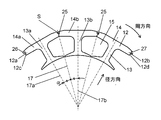
- FIG. 3 is a partially enlarged view of the stator core used in the electric motor according to Embodiment 1 of the present invention.
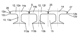
- FIG. 4 is an explanatory diagram illustrating a state in which a plurality of divided iron cores used in the electric motor according to Embodiment 1 of the present invention are arranged in a line.
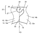
- FIG. 5A is an enlarged view of a main part for explaining a connecting portion of a split iron core used in the electric motor according to Embodiment 1 of the present invention.
- FIG. 5A is an enlarged view of a main part for explaining a connecting portion of a split iron core used in the electric motor according to Embodiment 1 of the present invention.
- FIG. 5B is an enlarged view of a main part for explaining a connecting portion of another divided core used in the electric motor according to Embodiment 1 of the present invention.
- FIG. 6 is an enlarged view of a main part for explaining the connecting part of the split iron core used in the electric motor according to Embodiment 2 of the present invention.
- the electric motor according to the embodiment of the present invention has an outer diameter of the yoke as much as possible with the center of rotation of the convex portion as much as possible when engaging the convex portion and the concave portion included in each of the adjacent divided cores by the configuration described later. Can be positioned on the side.
- a portion where the convex portion and the concave portion are engaged may be referred to as a connecting portion.
- the electric motor in the present embodiment can create a stator without losing the space around which the winding is wound. In other words, if the electric motor in the present embodiment is a stator of the same size, the area occupied by the yoke can be minimized. Therefore, the electric motor in the present embodiment can ensure a large space around which the winding is wound.
- the electric motor in the embodiment of the present invention is easy to work in the process of winding the winding. Furthermore, the electric motor in the present embodiment can increase the space around which the winding is wound while securing the path of the magnetic flux generated from the magnet. Therefore, the electric motor in the present embodiment can achieve further miniaturization and higher output of the electric motor.
- the conventional motor had the following points to be improved. That is, in the electric motor disclosed in Patent Document 1, the connected core segments can be connected in series with yokes arranged in a row. Therefore, in the electric motor disclosed in Patent Document 1, an overhang portion and an inclined portion are formed in each core segment. Therefore, in the electric motor disclosed in Patent Document 1, when the connected core segments are rounded to form a stator core, a notch that causes an air layer in which the magnetic flux is difficult to pass is formed in the path of the magnetic flux. Had occurred.
- the electric motor disclosed in Patent Document 1 had to increase the thickness of the yoke included in the core segment in the radial direction so as not to cause magnetic saturation in the path of the magnetic flux. Increasing the thickness of the yoke included in the core segment causes a loss of space around which the winding is wound. Therefore, the electric motor disclosed in Patent Document 1 is a factor that increases the size of the electric motor body and increases the cost.
- the electric motor according to the embodiment of the present invention eliminates the above-mentioned points to be improved, and provides an inexpensive and high-output electric motor without increasing the size of the electric motor.
- FIG. 1 is a perspective assembly view of an electric motor according to Embodiment 1 of the present invention.
- FIG. 1 shows main elements constituting the electric motor in the first embodiment.
- FIG. 2 is a cross-sectional view of the electric motor according to Embodiment 1 of the present invention.
- the windings are not shown for easy understanding of the description to be described later.
- FIG. 3 is a partially enlarged view of the stator core used in the electric motor according to Embodiment 1 of the present invention.
- FIG. 4 is an explanatory diagram illustrating a state in which a plurality of divided iron cores used in the electric motor according to Embodiment 1 of the present invention are arranged in a line.
- FIG. 5A is an enlarged view of a main part for explaining a connecting portion of a split iron core used in the electric motor according to Embodiment 1 of the present invention.
- FIG. 5B is an enlarged view of a main part for explaining a connecting portion of another divided core used in the electric motor according to Embodiment 1 of the present invention.
- the electric motor 10 includes a stator 11 and a rotor 21.
- the circumferential direction refers to a direction along the outer periphery of the stator core 11a having a cylindrical shape.
- the radial direction refers to the radial direction of the stator core 11a having a cylindrical shape.
- the outer diameter side means the outer peripheral side of the stator core 11a having a cylindrical shape in the radial direction.
- the inner diameter side means the center point O side of the stator core 11a having a cylindrical shape in the radial direction.
- the stator 11 has a stator core 11 a and a winding 16.
- the stator core 11a is formed in a ring shape by connecting a plurality of divided cores 14 together.
- Each divided iron core 14 has a yoke 12 and a tooth 13.
- a plurality of thin steel plates are laminated in the axial direction of the shaft 22.
- the yoke 12 has a first end 12a and a second end 12b and extends in the circumferential direction.
- the first end portion 12 a includes a convex portion 26 positioned on the outer diameter side and a first linear portion 12 c positioned on the inner diameter side of the convex portion 26.
- the first end 12a is located at one end in the circumferential direction.
- the second end 12b has a recess 27 located on the outer diameter side and a second linear portion 12d located on the inner diameter side of the recess 27.
- the second end portion 12b is located at the other end in the circumferential direction.
- the recess 27 includes an outer diameter side extending portion 28 positioned on the outer diameter side and an inner diameter side extending portion 29 positioned on the inner diameter side with respect to the outer diameter side extending portion 28.
- the teeth 13 are positioned so as to intersect with the yoke 12 and extend in the radial direction.
- the teeth 13 are formed on the inner peripheral side of the yoke 12.
- a slot 15 is located between adjacent teeth 13.
- the winding 16 is wound around the stator core 11a. Specifically, the winding 16 is wound around the teeth 13 included in the stator core 11a. The winding 16 is wound around the stator core 11a by a winding method such as concentrated winding or distributed winding. The wound winding 16 is accommodated in the slot 15.
- the rotor 21 is positioned facing the stator 11 and is rotatably supported.
- the rotor 21 has a rotor core 23 and a shaft 22 to which the rotor core 23 is fixed.
- the rotor core 23 is formed by laminating a plurality of thin steel plates in the axial direction of the shaft 22.
- a permanent magnet 24 is attached to the side wall of the rotor core 23 along the circumferential direction.
- the permanent magnet 24 is attached so that the N pole and the S pole are alternately positioned while having a predetermined interval.
- the rotor 21 is rotatably supported by a pair of bearings 40.
- the surface 24a of the permanent magnet 24 attached to the rotor 21 and the inner peripheral surface 13c of the teeth 13 included in the stator 11 are located facing each other through an air gap.
- the plurality of divided cores 14 are rotatably engaged with the convex portions 26 of the adjacent divided cores 14b and the concave portions 27 of the adjacent divided cores 14a.
- the rotation center S of the convex portion 26 is a line 17 that bisects an angle ⁇ formed by intersecting lines extending from the center lines 17a and 17b of the teeth 13 of each of the plurality of adjacent divided cores 14. Located on the top.
- the inner diameter side extending portion 29 protrudes toward the adjacent divided iron core 14b side from the bisecting line 17.
- the outer diameter side extension 28 includes a first tip 28a at the tip.
- the inner diameter side extension portion 29 includes a second tip portion 29a at the tip.
- the plurality of divided cores 14 include a convex portion 26 included in one of the plurality of adjacent divided cores 14 and a concave portion 27 included in the other of the plurality of adjacent divided cores 14. It is pivotally engaged. At this time, in the concave portion 27, the first tip portion 28 a is located on the outer diameter side with respect to the line 33 connecting the second tip portion 29 a and the rotation center S.
- the concave portion 27 is engaged with the convex portion 26 in a range exceeding 180 degrees around the rotation center S.
- the concave portion 27 may engage with the convex portion 26 in the range of more than 180 degrees and not more than 270 degrees around the rotation center S.
- the length h of the first linear portion 12c and the second linear portion 12d is 1/3 or more of the thickness H of the yoke 12.
- the length h of the first linear portion 12c and the second linear portion 12d is preferably not less than 1 ⁇ 2 of the thickness H of the yoke 12.
- the number of poles of the rotor 21 is “10”, and the number of slots of the stator 11 is “12”.
- the present invention is not limited to this combination, and can be applied to other combinations.
- the connecting portion 25 includes a convex portion 26 included in the first end portion 12 a included in one yoke 12, and a concave portion 27 included in the second end portion 12 b included in the other yoke 12. .
- the shape of the convex portion 26 and the shape of the concave portion 27 may be any shape as long as the engaged convex portion 26 and concave portion 27 are rotatable.
- the convex part 26 and the recessed part 27 which comprise the connection part 25 have the shape in which an air layer is hard to be formed even if the connected division
- the convex portion 26 and the concave portion 27 constituting the connecting portion 25 are each arc-shaped.
- the shape of the convex part 26 and the concave part 27 which comprise the connection part 25 is not limited to circular arc shape.
- the convex portion 26 and the concave portion 27 constituting the connecting portion 25 have the arc center of the convex portion 26 as the rotation center S.
- the connecting portion 25 is rotatable with the rotation center S as the center of the rotation operation.
- the plurality of divided iron cores 14 are connected to each other by a connecting portion 25.
- the connected divided iron cores 14 are rounded to form a cylindrical shape.
- the plurality of divided iron cores 14 formed in a cylindrical shape function as the stator iron core 11a.
- the convex portions 26 and the concave portions 27 constituting the connecting portion 25 function as a part of the yoke 12 through which the magnetic flux passes.
- the center line 17a is a center line of the teeth 13a included in the divided iron core 14a.
- the center line 17b is a center line of the teeth 13b of the split iron core 14b adjacent to the split iron core 14a.
- the center line 17a and the center line 17b intersect at an angle ⁇ .
- the rotation center S of the convex portion 26 is located on a line 17 that bisects the angle ⁇ .
- the yoke 12e included in the split core 14a and the yoke 12f included in the split core 14b adjacent to the split core 14a are arranged in a line.
- the teeth 13a included in the divided iron core 14a and the teeth 13b included in the divided iron core 14b adjacent to the divided iron core 14a are positioned so as to be parallel to each other.
- the teeth 13a and the teeth 13b are configured to be parallel to each other, the windings can be easily and continuously wound in the step of winding the windings around the split core 14. That is, the workability is improved in the process of winding the winding.
- the winding is wound to the back of the slot 15 with the windings aligned. Therefore, the winding is wound with high density around the stator core used in the electric motor according to the first embodiment. As a result, the electric motor in the first embodiment can be expected to increase the output.
- the inner diameter side extending portion 29 included in the concave portion 27 protrudes toward the adjacent divided iron core 14b from the bisecting line 17. If it is this structure, the range which the connection part 25 engages can be taken widely on the inner diameter side extension part 29 side. Therefore, there is no problem even if the shape of the outer diameter side extension portion 28 is reduced and the range of engagement on the outer diameter side extension portion 28 is reduced. Therefore, the electric motor in the first embodiment can position the rotation center S of the convex portion 26 relatively on the outer diameter side of the yoke 12.
- the connecting portions 25 rotate, the plurality of connected divided cores 14 can be changed into a ring shape or a serial body.
- the shape of the plurality of divided iron cores 14 changes from a serial body to an annular shape, an outer diameter side extending portion 28 included in the concave portion 27, and an outer surface 30 positioned on the outer diameter side of the yoke 12 including the convex portion 26 Therefore, it is necessary to form the notch 31 so as to prevent physical interference. If it is this structure, the dimension of the notch part 31 can be restrained to the minimum magnitude
- the notch 31 is an air layer through which magnetic flux is difficult to pass. Therefore, if the size of the notch 31 positioned on the outer diameter side of the connecting portion 25 can be minimized, the required magnetic flux can be passed through the stator core 11a. Therefore, in the radial direction, the thickness of the yoke 12 can be made thin enough not to cause magnetic saturation. In other words, the stator core 11a has a large space for winding the winding.
- the electric motor in the first embodiment can achieve high output, high efficiency, or downsizing.
- the connecting portion 25 is formed on the outer diameter side of the yoke 12.
- a linear portion 32 having a length h is formed on the inner diameter side of the connecting portion 25.
- the linear part 32 has the following effects.
- the linear part 32 improves the strength of the stator core 11a assembled in a cylindrical shape. Moreover, the linear part 32 improves the dimensional accuracy of the assembled stator core 11a.
- the electric motor in the first embodiment can suppress noise, vibration, and the like that occur when the assembled stator core 11a has low dimensional accuracy.
- length h of the linear portion 32 described above may be an arbitrary dimension.
- the length h of the linear portion 32 is preferably longer.
- the length h of the linear portion 32 is preferably 1/3 or more of the thickness H of the yoke 12.
- the length h of the linear portion 32 is preferably 1/2 or more of the thickness H of the yoke 12.
- angle ⁇ at which the convex portion 26 and the concave portion 27 that constitute the connecting portion 25 engage is larger than 180 degrees.
- the stator core 11a to which the plurality of divided cores 14 are connected is not disassembled. Further, no special jig is required to maintain the connected divided cores 14 in a line.
- stator used in the electric motor according to the first embodiment can be easily operated such as winding a winding, the workability is dramatically improved.
- the connecting wire included in the winding is less likely to be loaded, so that defects such as disconnection can be reduced.
- FIG. 6 is an enlarged view of a main part for explaining a connecting portion of a split iron core used in the electric motor according to Embodiment 2 of the present invention.
- the outer diameter side extending portion 28 is relative to a straight line 18 connecting the center point O of the annular stator and the rotation center S. , Located on the first end 12a side of the split core 14a.
- the second tip portion 29a is located on the side of the adjacent divided iron core 14b with respect to the straight line 18 connecting the center point O of the annular stator and the rotation center S.
- the center point O of the stator is the axis of the shaft 22.
- the plurality of divided iron cores 14 are deformed in an annular shape to form the stator iron core 11a.
- the outer diameter side extending portion 28 included in the concave portion 27 is not positioned on the straight line 18 passing through the center point O of the stator 11 and the rotation center S of the convex portion 26.
- the rotation center S of the convex portion 26 can be positioned as far as possible on the outer diameter side of the yoke 12.
- the connected divided cores 14 can be rotated to a state in which they are aligned.
- the plurality of divided cores 14 connected to each other are rounded to form a stator core 11a. At this time, it is not necessary to form a notch on the outer diameter side of the yoke 12 in the connecting portion 25.
- the stator iron core used in the electric motor according to the second embodiment can be the yoke 12 that can pass the magnetic flux required for the stator and has a minimum necessary thickness.
- the yoke 12 includes a connecting portion that is not magnetically saturated. Therefore, the stator core used for the electric motor according to the second embodiment can ensure a large space around which the winding is wound.
- the stator core used in the electric motor according to the second embodiment can wind many windings.
- the stator core used in the electric motor according to the second embodiment can use a thick wire having a lower resistance value as the winding. Therefore, the electric motor in the second embodiment can achieve high output, high efficiency, or downsizing.
- the teeth are formed from the yoke toward the outer diameter side.
- the relationship between the convex portion and the concave portion constituting the connecting portion is the same as that described above.
- the electric motor of the present invention is not particularly limited as long as it is an electric motor having a stator, and can be used in a wide range.
Landscapes
- Engineering & Computer Science (AREA)
- Power Engineering (AREA)
- Iron Core Of Rotating Electric Machines (AREA)
- Manufacture Of Motors, Generators (AREA)
Priority Applications (4)
| Application Number | Priority Date | Filing Date | Title |
|---|---|---|---|
| EP15815085.4A EP3166206B1 (de) | 2014-07-03 | 2015-06-26 | Elektromotor |
| JP2016531094A JP6627082B2 (ja) | 2014-07-03 | 2015-06-26 | 電動機 |
| US15/316,576 US20170149295A1 (en) | 2014-07-03 | 2015-06-26 | Electric motor |
| CN201580033341.1A CN106663972B (zh) | 2014-07-03 | 2015-06-26 | 电动机 |
Applications Claiming Priority (2)
| Application Number | Priority Date | Filing Date | Title |
|---|---|---|---|
| JP2014-137826 | 2014-07-03 | ||
| JP2014137826 | 2014-07-03 |
Publications (1)
| Publication Number | Publication Date |
|---|---|
| WO2016002174A1 true WO2016002174A1 (ja) | 2016-01-07 |
Family
ID=55018753
Family Applications (1)
| Application Number | Title | Priority Date | Filing Date |
|---|---|---|---|
| PCT/JP2015/003211 WO2016002174A1 (ja) | 2014-07-03 | 2015-06-26 | 電動機 |
Country Status (5)
| Country | Link |
|---|---|
| US (1) | US20170149295A1 (de) |
| EP (1) | EP3166206B1 (de) |
| JP (1) | JP6627082B2 (de) |
| CN (1) | CN106663972B (de) |
| WO (1) | WO2016002174A1 (de) |
Cited By (1)
| Publication number | Priority date | Publication date | Assignee | Title |
|---|---|---|---|---|
| JPWO2019111777A1 (ja) * | 2017-12-07 | 2020-11-19 | 京セラインダストリアルツールズ株式会社 | 固定子鉄心、固定子鉄心の製造方法 |
Families Citing this family (5)
| Publication number | Priority date | Publication date | Assignee | Title |
|---|---|---|---|---|
| DE112014006468T5 (de) * | 2014-04-16 | 2016-12-01 | Mitsubishi Electric Corporation | Ankerkern einer elektrischen Drehmaschine |
| CN107707044B (zh) * | 2017-11-21 | 2024-08-30 | 浙江联宜电机有限公司 | 铰链式定子铁芯 |
| DK3745559T3 (en) * | 2019-05-27 | 2022-06-07 | Magnax Bv | Stator til aksialfluxmaskine |
| DE102021106186A1 (de) * | 2021-03-15 | 2022-09-15 | Ebm-Papst Mulfingen Gmbh & Co. Kg | Modular aufgebautes, segmentiertes Statorpaket |
| CN113300495A (zh) * | 2021-05-21 | 2021-08-24 | 株式会社富士克 | 分割铁芯、环状铁芯及旋转电机 |
Citations (4)
| Publication number | Priority date | Publication date | Assignee | Title |
|---|---|---|---|---|
| JP2005185100A (ja) * | 2005-03-24 | 2005-07-07 | Matsushita Electric Ind Co Ltd | 電動機の固定子構成部材、電動機の固定子、電動機の製造方法 |
| JP2010259174A (ja) * | 2009-04-23 | 2010-11-11 | Harmonic Drive Syst Ind Co Ltd | モータステータの製造方法 |
| JP2010273449A (ja) * | 2009-05-21 | 2010-12-02 | Honda Motor Co Ltd | ステータの製造方法およびモータ |
| JP2011114989A (ja) * | 2009-11-30 | 2011-06-09 | Nisca Corp | 回転電機 |
Family Cites Families (8)
| Publication number | Priority date | Publication date | Assignee | Title |
|---|---|---|---|---|
| JP3568364B2 (ja) * | 1996-09-30 | 2004-09-22 | 松下電器産業株式会社 | 回転電機のコア |
| US7111380B2 (en) * | 2002-10-31 | 2006-09-26 | Emerson Electric Co. | Method for forming an annular stator assembly |
| JP4589153B2 (ja) * | 2005-03-09 | 2010-12-01 | アスモ株式会社 | 巻線方法、ステータの製造方法、及び巻線機 |
| US8299690B2 (en) * | 2009-03-23 | 2012-10-30 | Nisca Corporation | Stator structure and rotating electrical machine using the same |
| US8912702B2 (en) * | 2009-04-29 | 2014-12-16 | Ernesto Malvestiti S.P.A. | Process and mold for producing ferromagnetic cores of electric motors |
| JP5601799B2 (ja) * | 2009-07-10 | 2014-10-08 | パナソニック株式会社 | ステータおよびステータの製造方法 |
| CN102570645B (zh) * | 2012-01-31 | 2014-03-26 | 珠海格力电器股份有限公司 | 定子铁芯、电机及电机制作方法 |
| CN203481931U (zh) * | 2013-07-10 | 2014-03-12 | 广东美芝精密制造有限公司 | 用于压缩机的定子铁芯及具有该定子铁芯的压缩机 |
-
2015
- 2015-06-26 WO PCT/JP2015/003211 patent/WO2016002174A1/ja active Application Filing
- 2015-06-26 EP EP15815085.4A patent/EP3166206B1/de active Active
- 2015-06-26 JP JP2016531094A patent/JP6627082B2/ja active Active
- 2015-06-26 CN CN201580033341.1A patent/CN106663972B/zh active Active
- 2015-06-26 US US15/316,576 patent/US20170149295A1/en not_active Abandoned
Patent Citations (4)
| Publication number | Priority date | Publication date | Assignee | Title |
|---|---|---|---|---|
| JP2005185100A (ja) * | 2005-03-24 | 2005-07-07 | Matsushita Electric Ind Co Ltd | 電動機の固定子構成部材、電動機の固定子、電動機の製造方法 |
| JP2010259174A (ja) * | 2009-04-23 | 2010-11-11 | Harmonic Drive Syst Ind Co Ltd | モータステータの製造方法 |
| JP2010273449A (ja) * | 2009-05-21 | 2010-12-02 | Honda Motor Co Ltd | ステータの製造方法およびモータ |
| JP2011114989A (ja) * | 2009-11-30 | 2011-06-09 | Nisca Corp | 回転電機 |
Non-Patent Citations (1)
| Title |
|---|
| See also references of EP3166206A4 * |
Cited By (2)
| Publication number | Priority date | Publication date | Assignee | Title |
|---|---|---|---|---|
| JPWO2019111777A1 (ja) * | 2017-12-07 | 2020-11-19 | 京セラインダストリアルツールズ株式会社 | 固定子鉄心、固定子鉄心の製造方法 |
| JP7032436B2 (ja) | 2017-12-07 | 2022-03-08 | 京セラインダストリアルツールズ株式会社 | 固定子鉄心 |
Also Published As
| Publication number | Publication date |
|---|---|
| EP3166206A1 (de) | 2017-05-10 |
| CN106663972A (zh) | 2017-05-10 |
| US20170149295A1 (en) | 2017-05-25 |
| JP6627082B2 (ja) | 2020-01-08 |
| EP3166206A4 (de) | 2017-06-21 |
| CN106663972B (zh) | 2019-07-05 |
| EP3166206B1 (de) | 2019-05-22 |
| JPWO2016002174A1 (ja) | 2017-04-27 |
Similar Documents
| Publication | Publication Date | Title |
|---|---|---|
| WO2016002174A1 (ja) | 電動機 | |
| JP5885890B1 (ja) | 回転電機用固定子コア、回転電機及び回転電機の製造方法 | |
| JP2017077044A (ja) | 回転電機、回転子鉄心の製造方法 | |
| JP2007014110A (ja) | 回転電機 | |
| JP6388066B2 (ja) | ブラシレスモータ | |
| JP2005033941A (ja) | 永久磁石モータの固定子鉄心及び永久磁石モータ | |
| JP2009273304A (ja) | 回転電機のロータ及び回転電機 | |
| JP2017123725A (ja) | 回転電動機 | |
| JP2017204906A (ja) | スイッチトリラクタンスモータ | |
| JP5449715B2 (ja) | モータ | |
| JP2008109784A (ja) | ステータ構造 | |
| JP2007202363A (ja) | 回転電機 | |
| WO2014002181A1 (ja) | 永久磁石式回転電機、及びその製造方法 | |
| JP2018023232A (ja) | 回転電機および回転電機の製造方法 | |
| JP2011067070A (ja) | 電動機 | |
| JP2009284716A (ja) | アウタロータ型ブラシレスモータ | |
| JP2007181259A (ja) | ブラシレスモータ | |
| JP6012046B2 (ja) | ブラシレスモータ | |
| JP6357870B2 (ja) | 永久磁石式電動機 | |
| JP2013021774A (ja) | モータ | |
| JP2009038897A (ja) | アキシャルギャップ型モータ | |
| JP6337549B2 (ja) | 磁石埋込型ロータ | |
| JP2014082903A (ja) | ブラシレスモータ | |
| JP2008220143A (ja) | 回転電機のロータ及び回転電機 | |
| JP2006166515A (ja) | モータ及びその製造方法 |
Legal Events
| Date | Code | Title | Description |
|---|---|---|---|
| 121 | Ep: the epo has been informed by wipo that ep was designated in this application |
Ref document number: 15815085 Country of ref document: EP Kind code of ref document: A1 |
|
| REEP | Request for entry into the european phase |
Ref document number: 2015815085 Country of ref document: EP |
|
| WWE | Wipo information: entry into national phase |
Ref document number: 2015815085 Country of ref document: EP |
|
| WWE | Wipo information: entry into national phase |
Ref document number: 15316576 Country of ref document: US |
|
| ENP | Entry into the national phase |
Ref document number: 2016531094 Country of ref document: JP Kind code of ref document: A |
|
| NENP | Non-entry into the national phase |
Ref country code: DE |