JP2005033941A - 永久磁石モータの固定子鉄心及び永久磁石モータ - Google Patents
永久磁石モータの固定子鉄心及び永久磁石モータ Download PDFInfo
- Publication number
- JP2005033941A JP2005033941A JP2003271872A JP2003271872A JP2005033941A JP 2005033941 A JP2005033941 A JP 2005033941A JP 2003271872 A JP2003271872 A JP 2003271872A JP 2003271872 A JP2003271872 A JP 2003271872A JP 2005033941 A JP2005033941 A JP 2005033941A
- Authority
- JP
- Japan
- Prior art keywords
- permanent magnet
- rotor
- center
- gap length
- ratio
- Prior art date
- Legal status (The legal status is an assumption and is not a legal conclusion. Google has not performed a legal analysis and makes no representation as to the accuracy of the status listed.)
- Pending
Links
Images


Classifications
-
- H—ELECTRICITY
- H02—GENERATION; CONVERSION OR DISTRIBUTION OF ELECTRIC POWER
- H02K—DYNAMO-ELECTRIC MACHINES
- H02K1/00—Details of the magnetic circuit
- H02K1/06—Details of the magnetic circuit characterised by the shape, form or construction
- H02K1/12—Stationary parts of the magnetic circuit
- H02K1/14—Stator cores with salient poles
- H02K1/146—Stator cores with salient poles consisting of a generally annular yoke with salient poles
-
- H—ELECTRICITY
- H02—GENERATION; CONVERSION OR DISTRIBUTION OF ELECTRIC POWER
- H02K—DYNAMO-ELECTRIC MACHINES
- H02K1/00—Details of the magnetic circuit
- H02K1/06—Details of the magnetic circuit characterised by the shape, form or construction
- H02K1/12—Stationary parts of the magnetic circuit
- H02K1/16—Stator cores with slots for windings
-
- H—ELECTRICITY
- H02—GENERATION; CONVERSION OR DISTRIBUTION OF ELECTRIC POWER
- H02K—DYNAMO-ELECTRIC MACHINES
- H02K1/00—Details of the magnetic circuit
- H02K1/06—Details of the magnetic circuit characterised by the shape, form or construction
- H02K1/22—Rotating parts of the magnetic circuit
- H02K1/27—Rotor cores with permanent magnets
- H02K1/2706—Inner rotors
- H02K1/272—Inner rotors the magnetisation axis of the magnets being perpendicular to the rotor axis
- H02K1/274—Inner rotors the magnetisation axis of the magnets being perpendicular to the rotor axis the rotor consisting of two or more circumferentially positioned magnets
- H02K1/2753—Inner rotors the magnetisation axis of the magnets being perpendicular to the rotor axis the rotor consisting of two or more circumferentially positioned magnets the rotor consisting of magnets or groups of magnets arranged with alternating polarity
-
- H—ELECTRICITY
- H02—GENERATION; CONVERSION OR DISTRIBUTION OF ELECTRIC POWER
- H02K—DYNAMO-ELECTRIC MACHINES
- H02K15/00—Methods or apparatus specially adapted for manufacturing, assembling, maintaining or repairing of dynamo-electric machines
- H02K15/02—Methods or apparatus specially adapted for manufacturing, assembling, maintaining or repairing of dynamo-electric machines of stator or rotor bodies
- H02K15/03—Methods or apparatus specially adapted for manufacturing, assembling, maintaining or repairing of dynamo-electric machines of stator or rotor bodies having permanent magnets
-
- H—ELECTRICITY
- H02—GENERATION; CONVERSION OR DISTRIBUTION OF ELECTRIC POWER
- H02K—DYNAMO-ELECTRIC MACHINES
- H02K3/00—Details of windings
- H02K3/46—Fastening of windings on the stator or rotor structure
- H02K3/48—Fastening of windings on the stator or rotor structure in slots
Abstract
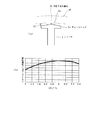
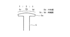
【解決手段】 固定子鉄心12を構成するティースヘッド5aの回転子永久磁石13と対向する側の面形状を、周方向の中央部5bが回転子の回転中心を中心とする円弧状で且つ両端部5c,5dが前記円弧の両端に夫々接する接線を成すように形成し、ティースヘッド5aと回転子永久磁石13とのエアギャップ長を、周方向の中央G1に対する両端G2の比率が略「2」となるように設定する。
【選択図】 図1
Description
この技術は、外転型のモータにおいて、ティースヘッドの回転子永久磁石と対向する側の面の形状を、周方向の中央部については回転子の回転中心を中心とする円弧状に形成し、その周方向中央部から周方向の両端部に向かうに従って滑らかに回転子永久磁石から遠ざかる形状としたものである。
本発明は上記事情に鑑みてなされたものであり、その目的は、回転時に発生する誘起電圧を低下させること無くコギングトルクの低減化をより効果的に図ることができる永久磁石形モータの固定子鉄心及び永久磁石形モータを提供することにある。
前記ティースの先端部におけるティースヘッドの回転子永久磁石と対向する側の面形状を前記永久磁石側に凸とすると共に、
前記ティースヘッドと回転子永久磁石との空隙長を、周方向の中央に対する両端の比率が1.4〜2.4の範囲となるように設定する。
また、請求項2に記載したように、ティースヘッドの回転子永久磁石と対向する側の面形状を前記永久磁石側に凸とすると共に、空隙長の比率を1.6〜2.2の範囲に設定し、更に、請求項3に記載したように、空隙長の比率を1.8〜2.0の範囲に設定すれば、誘起電圧とコギングトルクとの発生バランスがより最適となることが判った。
前記ティースの先端部におけるティースヘッドの回転子永久磁石と対向する側の面形状は、周方向の中央部が回転子の回転中心を中心とする円弧状で且つ両端部が前記円弧の両端に夫々接する接線を成すように形成すると共に、
前記ティースヘッドと回転子永久磁石との空隙長は、周方向の中央に対する両端の比率が1.6〜2.6の範囲となるように設定する。
そして、この場合も、請求項5に記載したように、空隙長の比率を1.8〜2.4の範囲に設定し、更に、請求項6に記載したように、前記空隙長の比率を2.0〜2.2の範囲に設定すれば、誘起電圧とコギングトルクとの発生バランスがより最適となる。
以下、本発明を外転形の永久磁石形モータに適用した場合の第1実施例について図1乃至図4を参照して説明する。まず、図4には、外転形の永久磁石形モータ1の縦断面図が示されている。この図4において、固定子鉄心2は、ケイ素鋼板を打ち抜いたリング状のものを多数枚積層して構成されたもので、これの中央部には軸受3を装着するための円形の孔4が形成され、外周部には、図3に示すように、この場合12個のティース5が周方向に設けられている。
これに対して、回転子10は、上記軸受3に回転自在に支承された回転軸11と、この回転軸11の上端部に固着された回転子ヨーク12と、この回転子ヨーク12の筒部12aの内周面に設けられた円筒状をなす回転子永久磁石13とから構成されていて、この回転子永久磁石13が、固定子鉄心2におけるティース5のティースヘッド5aに対してエアギャップ(空隙)を介して径方向から対向するように配置されている。
(誘起電圧)/(コギングトルク)は略最大を示すことが判った。
図5は本発明の第2実施例を示すものであり、第1実施例と同一部分には同一符号を付して説明を省略し、以下異なる部分についてのみ説明する。第2実施例では、ティース15のティースヘッド15aの形状が、ティースヘッド5aとは若干異なっている。
以上のように第2実施例によれば、ティースヘッド15aが回転子永久磁石13と対向する側の面形状を回転子永久磁石13側に凸となる円筒面として、中央におけるエアギャップ長G1’と両端におけるエアギャップ長G2’との比が10:19となるように設定した。従って、第1実施例と略同様の効果が得られる。
図6は本発明の第3実施例を示したものである。第3実施例では、本発明を内転形の永久磁石形モータ20に適用したものである。固定子における固定子鉄心16には、内周部側に8個のティース17が設けられている。この固定子鉄心16の中心部に、回転子永久磁石18を備えた回転子19が回転可能に配設されている。そして、ティース17のティースヘッド17aにおける回転子永久磁石18と対向する側の面の形状は、それぞれ固定子鉄心16の外周方向にずれた位置を中心とする円弧状(円筒面)に形成されている。
G4/G3=2となるように設定されている。
本発明は上記し且つ図面に記載した実施例にのみ限定されるものではなく、以下のような変形または拡張が可能である。
第1実施例において、ティースヘッドと回転子永久磁石とのエアギャップ長比G2/G1は「2」とするものに限らない。例えば、エアギャップ長比を2.0〜2.2の範囲や、1.8〜2.4の範囲、或いは1.6〜2.6の範囲に設定した場合でも、有利な効果を得ることは可能である。
Claims (7)
- 複数個のティースを回転軸に対して放射状に配置してなり、
前記ティースの先端部におけるティースヘッドの回転子永久磁石と対向する側の面形状を前記永久磁石側に凸とすると共に、
前記ティースヘッドと回転子永久磁石との空隙長は、周方向の中央に対する両端の比率が1.4〜2.4の範囲となるように設定されていることを特徴とする永久磁石形モータの固定子鉄心。 - ティースヘッドの回転子永久磁石と対向する側の面形状を前記永久磁石側に凸とすると共に、
空隙長は、周方向の中央に対する両端の比率が1.6〜2.2の範囲に設定されていることを特徴とする請求項1記載の永久磁石形モータの固定子鉄心。 - 空隙長は、周方向の中央に対する両端の比率が1.8〜2.0の範囲に設定されていることを特徴とする請求項2記載の永久磁石形モータの固定子鉄心。
- 複数個のティースを回転軸に対して放射状に配置してなり、
前記ティースの先端部におけるティースヘッドの回転子永久磁石と対向する側の面形状は、周方向の中央部が回転子の回転中心を中心とする円弧状で且つ両端部が前記円弧の両端に夫々接する接線を成し、
前記ティースヘッドと回転子永久磁石との空隙長は、周方向の中央に対する両端の比率が1.6〜2.6の範囲となるように設定されていることを特徴とする永久磁石形モータの固定子鉄心。 - 空隙長は、周方向の中央に対する両端の比率が1.8〜2.4の範囲に設定されていることを特徴とする請求項4記載の永久磁石形モータの固定子鉄心。
- 空隙長は、周方向の中央に対する両端の比率が2.0〜2.2の範囲に設定されていることを特徴とする請求項5載の永久磁石形モータの固定子鉄心。
- 請求項1乃至6の何れかに記載の固定子鉄心を備えた永久磁石形モータ。
Priority Applications (2)
| Application Number | Priority Date | Filing Date | Title |
|---|---|---|---|
| JP2003271872A JP2005033941A (ja) | 2003-07-08 | 2003-07-08 | 永久磁石モータの固定子鉄心及び永久磁石モータ |
| KR1020040051862A KR100723329B1 (ko) | 2003-07-08 | 2004-07-05 | 영구자석 모터의 고정자 철심 및 영구자석 모터 |
Applications Claiming Priority (1)
| Application Number | Priority Date | Filing Date | Title |
|---|---|---|---|
| JP2003271872A JP2005033941A (ja) | 2003-07-08 | 2003-07-08 | 永久磁石モータの固定子鉄心及び永久磁石モータ |
Publications (2)
| Publication Number | Publication Date |
|---|---|
| JP2005033941A true JP2005033941A (ja) | 2005-02-03 |
| JP2005033941A5 JP2005033941A5 (ja) | 2006-04-27 |
Family
ID=34209597
Family Applications (1)
| Application Number | Title | Priority Date | Filing Date |
|---|---|---|---|
| JP2003271872A Pending JP2005033941A (ja) | 2003-07-08 | 2003-07-08 | 永久磁石モータの固定子鉄心及び永久磁石モータ |
Country Status (2)
| Country | Link |
|---|---|
| JP (1) | JP2005033941A (ja) |
| KR (1) | KR100723329B1 (ja) |
Cited By (26)
| Publication number | Priority date | Publication date | Assignee | Title |
|---|---|---|---|---|
| JP2006238667A (ja) * | 2005-02-28 | 2006-09-07 | Matsushita Electric Ind Co Ltd | 電動機 |
| WO2006126552A1 (ja) * | 2005-05-24 | 2006-11-30 | Denso Corporation | モータとその制御装置 |
| JP2008043071A (ja) * | 2006-08-07 | 2008-02-21 | Denso Corp | ステッピングモータとその製造方法 |
| JP2009089547A (ja) * | 2007-10-02 | 2009-04-23 | Hitachi Appliances Inc | ブラシレスモータ |
| CN102244446A (zh) * | 2010-05-11 | 2011-11-16 | 天津市松正电动科技有限公司 | 一种永磁同步电机 |
| JP2012023944A (ja) * | 2010-06-15 | 2012-02-02 | Alphana Technology Co Ltd | 回転機器 |
| CN102594076A (zh) * | 2012-03-09 | 2012-07-18 | 江门市凯斯莱工贸有限公司 | 一种可变频的三相无刷永磁电机 |
| CN104410180A (zh) * | 2014-12-11 | 2015-03-11 | 东南大学 | 一种e形定子铁心磁通切换型混合永磁记忆电机 |
| CN104617720A (zh) * | 2015-01-27 | 2015-05-13 | 华北电力大学(保定) | 用于削弱永磁同步发电机齿槽转矩的方法 |
| CN104734446A (zh) * | 2015-04-09 | 2015-06-24 | 莱克电气股份有限公司 | 一种内置式永磁同步电机 |
| WO2017011682A1 (en) * | 2015-07-16 | 2017-01-19 | Bergstrom, Inc. | Combination structure between stator and rotor in a brushless motor |
| CN106712346A (zh) * | 2016-12-15 | 2017-05-24 | 广东威灵电机制造有限公司 | 电机和具有其的水泵 |
| US10205363B2 (en) | 2015-07-16 | 2019-02-12 | Bergstrom, Inc. | Locating structure between printed circuit board and insulating bobbin in a brushless motor |
| US10218239B2 (en) | 2015-07-16 | 2019-02-26 | Bergstrom, Inc. | Brushless motor having terminal fixing blocks |
| US10263488B2 (en) | 2015-07-16 | 2019-04-16 | Bergstrom, Inc. | Stator with insulating bobbin in a brushless motor |
| US10527332B2 (en) | 2016-01-13 | 2020-01-07 | Bergstrom, Inc. | Refrigeration system with superheating, sub-cooling and refrigerant charge level control |
| US10562372B2 (en) | 2016-09-02 | 2020-02-18 | Bergstrom, Inc. | Systems and methods for starting-up a vehicular air-conditioning system |
| US10589598B2 (en) | 2016-03-09 | 2020-03-17 | Bergstrom, Inc. | Integrated condenser and compressor system |
| US10675948B2 (en) | 2016-09-29 | 2020-06-09 | Bergstrom, Inc. | Systems and methods for controlling a vehicle HVAC system |
| US10703173B2 (en) | 2016-08-22 | 2020-07-07 | Bergstrom, Inc. | Multi-compressor climate system |
| US10724772B2 (en) | 2016-09-30 | 2020-07-28 | Bergstrom, Inc. | Refrigerant liquid-gas separator having an integrated check valve |
| CN112039234A (zh) * | 2019-06-03 | 2020-12-04 | 通用汽车环球科技运作有限责任公司 | 具有减少基于绕组的功率损耗的定子齿尖端轮廓的电机 |
| CN112152411A (zh) * | 2019-10-16 | 2020-12-29 | 中山悦莱智能科技有限公司 | 一种三相无刷永磁直流电机 |
| US10967709B2 (en) | 2015-03-09 | 2021-04-06 | Bergstrom, Inc. | Graphical user interfaces for remotely managing climate control systems of a fleet of vehicles |
| US11420496B2 (en) | 2018-04-02 | 2022-08-23 | Bergstrom, Inc. | Integrated vehicular system for conditioning air and heating water |
| US11448441B2 (en) | 2017-07-27 | 2022-09-20 | Bergstrom, Inc. | Refrigerant system for cooling electronics |
Families Citing this family (4)
| Publication number | Priority date | Publication date | Assignee | Title |
|---|---|---|---|---|
| KR101228453B1 (ko) * | 2006-12-12 | 2013-01-31 | 엘지전자 주식회사 | 전기 모터 |
| KR100878565B1 (ko) * | 2007-08-08 | 2009-01-15 | 주식회사 원진일렉트로닉스 | 무브러시 직류 모터의 코깅 토크 저감 장치 |
| KR101770028B1 (ko) | 2014-08-25 | 2017-08-21 | 한온시스템 주식회사 | 브러시리스 모터 |
| KR102238353B1 (ko) * | 2019-09-20 | 2021-04-09 | 엘지전자 주식회사 | 분할코어를 구비한 전동기 및 그의 제조방법 |
Family Cites Families (2)
| Publication number | Priority date | Publication date | Assignee | Title |
|---|---|---|---|---|
| JPH11178298A (ja) * | 1997-12-15 | 1999-07-02 | Toshiba Corp | 永久磁石形モータの固定子鉄心及び永久磁石形モータ |
| KR100519616B1 (ko) * | 2002-12-13 | 2005-10-11 | 안승한 | 양각문양이 형성된 콘크리트 칼라 구조물 및 그 시공방법 |
-
2003
- 2003-07-08 JP JP2003271872A patent/JP2005033941A/ja active Pending
-
2004
- 2004-07-05 KR KR1020040051862A patent/KR100723329B1/ko not_active IP Right Cessation
Cited By (35)
| Publication number | Priority date | Publication date | Assignee | Title |
|---|---|---|---|---|
| JP2006238667A (ja) * | 2005-02-28 | 2006-09-07 | Matsushita Electric Ind Co Ltd | 電動機 |
| WO2006126552A1 (ja) * | 2005-05-24 | 2006-11-30 | Denso Corporation | モータとその制御装置 |
| US7911107B2 (en) | 2005-05-24 | 2011-03-22 | Denso Corporation | AC electric motor |
| JP2008043071A (ja) * | 2006-08-07 | 2008-02-21 | Denso Corp | ステッピングモータとその製造方法 |
| JP2009089547A (ja) * | 2007-10-02 | 2009-04-23 | Hitachi Appliances Inc | ブラシレスモータ |
| CN102244446A (zh) * | 2010-05-11 | 2011-11-16 | 天津市松正电动科技有限公司 | 一种永磁同步电机 |
| JP2012023944A (ja) * | 2010-06-15 | 2012-02-02 | Alphana Technology Co Ltd | 回転機器 |
| CN102594076A (zh) * | 2012-03-09 | 2012-07-18 | 江门市凯斯莱工贸有限公司 | 一种可变频的三相无刷永磁电机 |
| CN104410180A (zh) * | 2014-12-11 | 2015-03-11 | 东南大学 | 一种e形定子铁心磁通切换型混合永磁记忆电机 |
| CN104617720A (zh) * | 2015-01-27 | 2015-05-13 | 华北电力大学(保定) | 用于削弱永磁同步发电机齿槽转矩的方法 |
| CN104617720B (zh) * | 2015-01-27 | 2018-08-24 | 华北电力大学(保定) | 用于削弱永磁同步发电机齿槽转矩的方法 |
| US11780292B2 (en) | 2015-03-09 | 2023-10-10 | Bergstrom, Inc. | Graphical user interfaces for remotely managing climate control systems of a fleet of vehicles |
| US10967709B2 (en) | 2015-03-09 | 2021-04-06 | Bergstrom, Inc. | Graphical user interfaces for remotely managing climate control systems of a fleet of vehicles |
| CN104734446A (zh) * | 2015-04-09 | 2015-06-24 | 莱克电气股份有限公司 | 一种内置式永磁同步电机 |
| US10263488B2 (en) | 2015-07-16 | 2019-04-16 | Bergstrom, Inc. | Stator with insulating bobbin in a brushless motor |
| US10218239B2 (en) | 2015-07-16 | 2019-02-26 | Bergstrom, Inc. | Brushless motor having terminal fixing blocks |
| US10205363B2 (en) | 2015-07-16 | 2019-02-12 | Bergstrom, Inc. | Locating structure between printed circuit board and insulating bobbin in a brushless motor |
| US10320274B2 (en) | 2015-07-16 | 2019-06-11 | Bergstrom, Inc. | Combination structure between stator and rotor in a brushless motor |
| WO2017011682A1 (en) * | 2015-07-16 | 2017-01-19 | Bergstrom, Inc. | Combination structure between stator and rotor in a brushless motor |
| US10527332B2 (en) | 2016-01-13 | 2020-01-07 | Bergstrom, Inc. | Refrigeration system with superheating, sub-cooling and refrigerant charge level control |
| US10589598B2 (en) | 2016-03-09 | 2020-03-17 | Bergstrom, Inc. | Integrated condenser and compressor system |
| US11479086B2 (en) | 2016-08-22 | 2022-10-25 | Bergstrom, Inc. | Multi-compressor climate system |
| US10703173B2 (en) | 2016-08-22 | 2020-07-07 | Bergstrom, Inc. | Multi-compressor climate system |
| US10562372B2 (en) | 2016-09-02 | 2020-02-18 | Bergstrom, Inc. | Systems and methods for starting-up a vehicular air-conditioning system |
| US11712946B2 (en) | 2016-09-29 | 2023-08-01 | Bergstrom, Inc. | Systems and methods for controlling a vehicle HVAC system |
| US11241939B2 (en) | 2016-09-29 | 2022-02-08 | Bergstrom, Inc. | Systems and methods for controlling a vehicle HVAC system |
| US10675948B2 (en) | 2016-09-29 | 2020-06-09 | Bergstrom, Inc. | Systems and methods for controlling a vehicle HVAC system |
| US11512883B2 (en) | 2016-09-30 | 2022-11-29 | Bergstrom, Inc. | Refrigerant liquid-gas separator |
| US10724772B2 (en) | 2016-09-30 | 2020-07-28 | Bergstrom, Inc. | Refrigerant liquid-gas separator having an integrated check valve |
| CN106712346A (zh) * | 2016-12-15 | 2017-05-24 | 广东威灵电机制造有限公司 | 电机和具有其的水泵 |
| US11448441B2 (en) | 2017-07-27 | 2022-09-20 | Bergstrom, Inc. | Refrigerant system for cooling electronics |
| US11420496B2 (en) | 2018-04-02 | 2022-08-23 | Bergstrom, Inc. | Integrated vehicular system for conditioning air and heating water |
| US11919364B2 (en) | 2018-04-02 | 2024-03-05 | Bergstrom, Inc. | Integrated vehicular system for conditioning air and heating water |
| CN112039234A (zh) * | 2019-06-03 | 2020-12-04 | 通用汽车环球科技运作有限责任公司 | 具有减少基于绕组的功率损耗的定子齿尖端轮廓的电机 |
| CN112152411A (zh) * | 2019-10-16 | 2020-12-29 | 中山悦莱智能科技有限公司 | 一种三相无刷永磁直流电机 |
Also Published As
| Publication number | Publication date |
|---|---|
| KR20050006040A (ko) | 2005-01-15 |
| KR100723329B1 (ko) | 2007-05-31 |
Similar Documents
| Publication | Publication Date | Title |
|---|---|---|
| JP2005033941A (ja) | 永久磁石モータの固定子鉄心及び永久磁石モータ | |
| JP2007014110A (ja) | 回転電機 | |
| JPH11178298A (ja) | 永久磁石形モータの固定子鉄心及び永久磁石形モータ | |
| JP2005176424A (ja) | 回転電機の回転子 | |
| JP2012120326A (ja) | 磁石埋め込み型回転子、電動機及び電動機の組立方法 | |
| JP2006311772A (ja) | 電動機 | |
| JP2006320109A (ja) | 回転電機、及び回転電機の製造方法 | |
| JP6279763B2 (ja) | 誘導電動機 | |
| JP2007028868A (ja) | 回転電機の固定子 | |
| JP2007151293A (ja) | モータ | |
| JP2008029078A (ja) | 永久磁石形同期電動機 | |
| JP2006288042A (ja) | 永久磁石形モータ | |
| JP6627082B2 (ja) | 電動機 | |
| JP2006238618A (ja) | モータ | |
| JP2017123725A (ja) | 回転電動機 | |
| JP2003284276A (ja) | 回転電機 | |
| JP6601169B2 (ja) | 回転電機 | |
| JP2010178471A (ja) | 回転電機 | |
| JP5248048B2 (ja) | 回転電機の回転子及び回転電機 | |
| JP2009273304A (ja) | 回転電機のロータ及び回転電機 | |
| JP2004320989A (ja) | 永久磁石埋込型モータ | |
| JP2006262603A (ja) | 回転電機 | |
| JP2009106001A (ja) | 回転電機 | |
| JP2010207021A (ja) | 回転子用エンドプレートおよびこれを用いた回転電機 | |
| KR20160080500A (ko) | 스테이터 및 이를 모터 |
Legal Events
| Date | Code | Title | Description |
|---|---|---|---|
| A521 | Written amendment |
Free format text: JAPANESE INTERMEDIATE CODE: A523 Effective date: 20060310 |
|
| A621 | Written request for application examination |
Free format text: JAPANESE INTERMEDIATE CODE: A621 Effective date: 20060310 |
|
| A977 | Report on retrieval |
Free format text: JAPANESE INTERMEDIATE CODE: A971007 Effective date: 20070611 |
|
| A131 | Notification of reasons for refusal |
Free format text: JAPANESE INTERMEDIATE CODE: A131 Effective date: 20070828 |
|
| A521 | Written amendment |
Free format text: JAPANESE INTERMEDIATE CODE: A523 Effective date: 20071024 |
|
| A02 | Decision of refusal |
Free format text: JAPANESE INTERMEDIATE CODE: A02 Effective date: 20080304 |
|
| A521 | Written amendment |
Free format text: JAPANESE INTERMEDIATE CODE: A523 Effective date: 20080422 |
|
| A911 | Transfer of reconsideration by examiner before appeal (zenchi) |
Free format text: JAPANESE INTERMEDIATE CODE: A911 Effective date: 20080508 |
|
| A912 | Removal of reconsideration by examiner before appeal (zenchi) |
Free format text: JAPANESE INTERMEDIATE CODE: A912 Effective date: 20080627 |