WO2015198984A1 - 遠心機 - Google Patents
遠心機 Download PDFInfo
- Publication number
- WO2015198984A1 WO2015198984A1 PCT/JP2015/067721 JP2015067721W WO2015198984A1 WO 2015198984 A1 WO2015198984 A1 WO 2015198984A1 JP 2015067721 W JP2015067721 W JP 2015067721W WO 2015198984 A1 WO2015198984 A1 WO 2015198984A1
- Authority
- WO
- WIPO (PCT)
- Prior art keywords
- protector
- centrifuge
- side wall
- rotor
- bottom plate
- Prior art date
- Legal status (The legal status is an assumption and is not a legal conclusion. Google has not performed a legal analysis and makes no representation as to the accuracy of the status listed.)
- Ceased
Links
Images



Classifications
-
- B—PERFORMING OPERATIONS; TRANSPORTING
- B04—CENTRIFUGAL APPARATUS OR MACHINES FOR CARRYING-OUT PHYSICAL OR CHEMICAL PROCESSES
- B04B—CENTRIFUGES
- B04B15/00—Other accessories for centrifuges
- B04B15/02—Other accessories for centrifuges for cooling, heating, or heat insulating
-
- B—PERFORMING OPERATIONS; TRANSPORTING
- B04—CENTRIFUGAL APPARATUS OR MACHINES FOR CARRYING-OUT PHYSICAL OR CHEMICAL PROCESSES
- B04B—CENTRIFUGES
- B04B7/00—Elements of centrifuges
- B04B7/02—Casings; Lids
-
- B—PERFORMING OPERATIONS; TRANSPORTING
- B04—CENTRIFUGAL APPARATUS OR MACHINES FOR CARRYING-OUT PHYSICAL OR CHEMICAL PROCESSES
- B04B—CENTRIFUGES
- B04B7/00—Elements of centrifuges
- B04B7/02—Casings; Lids
- B04B7/06—Safety devices ; Regulating
-
- B—PERFORMING OPERATIONS; TRANSPORTING
- B04—CENTRIFUGAL APPARATUS OR MACHINES FOR CARRYING-OUT PHYSICAL OR CHEMICAL PROCESSES
- B04B—CENTRIFUGES
- B04B7/00—Elements of centrifuges
- B04B7/02—Casings; Lids
- B04B7/06—Safety devices ; Regulating
- B04B2007/065—Devices and measures in the event of rotor fracturing, e.g. lines of weakness, stress regions
Definitions
- the present invention relates to a centrifuge (centrifuge) that rotates a rotor on which a sample is mounted.
- a centrifuge is used to separate a sample (for example, culture solution, blood, etc.) for each substance having a different density by centrifugal force during high-speed rotation, or to purify and analyze the sample.
- a sample for example, culture solution, blood, etc.
- a centrifuge a tube in which a sample is sealed is attached to a metal rotor that rotates at a high speed, and the rotor rotates at a high speed of, for example, about 20000 rpm.
- the type of rotor varies depending on the sample, the purpose of separation, and the sample volume to be separated.
- an angle rotor that is fixed to the rotor with a constant angle between them while the tube is tilted from the rotation axis, or a bucket loaded with the tube oscillates with rotation and remains horizontal during centrifugation.
- a swing rotor or the like whose state is maintained is used.
- a rotor that can apply a particularly high acceleration to a small amount of sample, or a rotor that can apply a relatively low acceleration to a large-capacity sample is selected as appropriate. For this reason, a plurality of types of rotors are selected and used in a single centrifuge, and the replacement work is easily performed.
- a large opening is formed above the rotor chamber in which the rotor is accommodated. And the opening can be opened and closed by a door.
- a refrigeration pipe is provided around the rotor chamber, and the refrigerant passes through the interior of the rotor chamber in order to control the temperature of the rotor chamber.
- the door that seals the opening is configured such that the opening can be reliably sealed and the opening and closing operation can be easily performed.
- FIG. 3 is a cross-sectional view showing the configuration of such a centrifuge 200.
- the rotor 201 is configured to rotate by a motor 203 in a bowl-shaped bowl 202 whose upper side is open.
- the outside of the bowl 202 is further surrounded by a heat insulating layer 205 while being wound around the refrigeration pipe 204.
- the temperature of the bowl 202 and the rotor 201 therein can be controlled during the centrifugal separation process.
- the upper side of the bowl 202 is sealed by a door 206 that can be opened and closed, and the rotor 201 is sealed in a rotor chamber 220 in the bowl 202.
- the above structure is housed in a metal box-shaped frame 207.
- the frame 207 is configured by welding and integrating a frame side wall portion 207A that is the outermost side when viewed from the rotation shaft 203A of the rotor 201 (motor 203) and a partition plate 207B having a horizontal surface shape.
- the motor 203 is installed so as to protrude upward from the partition plate 207B, and the bowl 202, the heat insulating layer 205, and the like are installed on the upper side of the partition plate 207B so as to be surrounded by the frame side wall portion 207A.
- a table 208 is provided on the upper side of the bowl 202, and a packing 209 is interposed between the table 208 and the bowl 202, and between the table 208 and the door 206, and the space between them is sealed. Further, at the lower part of the bowl 202, the space between the rotary shaft 203A and the bowl 202 is sealed with a seal rubber 210.
- the bowl 202 and the heat insulating layer 205 are made of a material having a low mechanical strength because the bowl 202 around the rotor 201 is thin and the heat insulating layer 205 is thick in order to increase the accuracy of temperature control.
- the mechanical strength of is low.
- the cylindrical protector 211 made of a thick steel plate is provided between the frame 207 (the frame side wall portion 207A) and the heat insulating layer 205.
- the central axis of the cylindrical protector 211 is substantially equal to the rotation axis 203A.
- the protector 211 absorbs energy when the rotor 201 is broken as described above, suppresses deformation and breakage of the entire centrifuge 200, and suppresses scattering of fragments of the rotor 201 to the outside of the centrifuge 200.
- the fragments are scattered at high speed outward in the radial direction when viewed from the rotating shaft 203A due to centrifugal force.
- the protector 211 having a circular cross-sectional shape in the horizontal plane may be deformed so that the cross-sectional shape becomes an ellipse whose major axis is the two directions.
- FIG. 4 is a perspective view of the protector 211 used here.
- the protector 211 needs to be resistant to an impact caused by debris scattered from the extending direction (vertical direction) of the rotating shaft 203A toward the outside in the horizontal direction.
- the protector 211 normally, has a simple cylindrical shape with the rotation axis 203A as the central axis, and the protector 211 has a narrow gap between the heat insulating layer 205 on the inner side and the frame side wall on the outer side.
- the size and the thickness are such that the distance from 207A is also narrow.
- the outer diameter of the heat insulation layer 205 is set according to the required temperature control performance.
- the protector 211 is often manufactured by rolling a sheet metal having a thickness of about 2 to 3 mm. Even such a protector 211 is made so that the rotational energy of the rotor can be received sufficiently.
- the centrifuge 200 having a large rotational energy it is necessary to make the thickness of the protector 210 larger than this, so that it is difficult to use one manufactured by roll processing.
- the protector 211 in order to reduce the cost of the centrifuge 200 itself, it is necessary to configure the protector 211 so that the protector 211 can be easily manufactured using a standard steel material.
- the protector 211 is often formed using a standard steel pipe having a large thickness. In such a case, the wall thickness and outer diameter are determined by the standard of the standard product, and the degree of freedom of setting is small.
- a steel pipe larger than a steel pipe having a desired thickness and size is often selected and used.
- a steel pipe having a desired thickness and size is often selected and used.
- the heat insulation layer 205 is sufficiently thick in the radial direction. growing.
- Patent Document 2 the shape of the protector itself is a simple cylindrical shape, but the protector has a two-layer structure made of two types of hard and soft materials to absorb impact and suppress deformation of the entire protector. Is described.
- Patent Document 3 describes a technique for similarly suppressing the deformation of the entire protector using a protector configured by combining a steel pipe and a reinforcing fiber. In these technologies, the centrifuge can be reduced in weight and size without increasing the size of the protector.
- JP 2005-349260 A Japanese Patent Laid-Open No. 50-56888 Japanese Utility Model Publication No. 62-91032 JP 2005-305400 A
- the thickness of the protector is simply increased and the size is increased, not only the size of the protector itself but also the size of the frame provided on the outside thereof needs to be increased. For this reason, the whole centrifuge becomes large, and it may be difficult to carry in and carry the centrifuge. In addition, the total weight of the centrifuge increased.
- the present invention has been made in view of such problems, and an object thereof is to provide an invention that solves the above problems.
- the present invention has the following configurations.
- a rotor chamber containing a rotor rotating around a rotation shaft is sealed from one side in the rotation shaft direction by a door capable of opening and closing, and the rotor chamber is sealed with the rotation shaft.
- the centrifuge includes a protector that surrounds the rotor chamber, and the protector includes a side wall portion that surrounds the rotor chamber and a plate portion that supports the inner surface of the side wall portion.
- the protector is configured by combining the side wall portion and the plate portion, which are separately formed, respectively.
- the centrifuge of the present invention is characterized in that, in the protector, the side wall portion and the plate portion are integrated.
- the centrifuge of the present invention is characterized in that, in the protector, the inner surface has a cylindrical shape, and the plate portion includes an outer peripheral surface fitted to the inner surface.
- a heat insulating layer is provided between the rotor chamber and the protector.
- the plate portion is placed on the surface of the partition plate having a surface intersecting the rotation axis.
- the centrifuge of the present invention is characterized in that the plate portion is fixed to the partition plate using a fixture.
- the centrifuge of the present invention is characterized in that the fixing by the fixing tool is released when a rotational torque of a certain level or more is applied to the protector.
- the present invention is configured as described above, it is possible to obtain a centrifuge in which deformation at the time of impact is suppressed and a lightweight and inexpensive protector is used.
- centrifuge centrifuge
- a protector that surrounds the rotor chamber and absorbs energy when the rotor is broken is used, as in the configuration of FIG.
- this protector can be made light and inexpensive with its deformation suppressed.
- FIG. 1 is a cross-sectional view showing the configuration of the centrifuge 1 and corresponds to FIG.
- the rotor 10 is provided in the rotor chamber 20.
- the protector 30 for suppressing the scattering of the fragments to the outside is used even when the rotor 10 is broken during rotation so as to surround the rotor chamber 20.
- the centrifuge 1 is characterized by the structure of the protector 30.
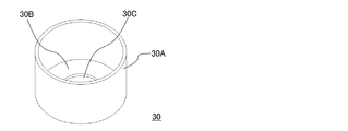
- FIG. 2 is a perspective view showing the configuration of the protector 30.
- the protector 30 includes two members, a side wall portion 30A having a cylindrical shape similar to the protector 211, and an annular bottom plate portion (plate portion) 30B that supports the inner surface of the lower end side of the side wall portion 30A from the inside. Consists of. As shown in FIG. 1, the bottom plate portion 30B is installed on the frame 16 (partition plate 16B), and the upper portion of the motor 12 including the rotary shaft 12A protrudes upward from a bottom plate portion opening 30C provided at the center portion thereof. To do.
- the side wall portion 30A is configured to surround the heat insulating layer 14 and the bottom plate portion 30B on the partition plate 16B.
- the lower inner surface of the side wall portion 30A is in contact with the bottom plate portion 30B and supported by the bottom plate portion 30B.
- the side wall portion 30A and the bottom plate portion 30B are both made of a steel plate having high mechanical strength. Further, the side wall portion 30A and the bottom plate portion 30B may be made of different materials.
- the bottom plate portion 30B can be made of an aluminum alloy or a titanium alloy. In this case, the bottom plate 30B can be reduced in weight even when the thickness of the bottom plate 30B is increased as compared with the case where the bottom plate 30B is made thicker, the centrifuge can be reduced in weight, and the assemblability can be improved.
- the bottom plate portion 30B is installed on the partition plate 16B on which the motor 12 is installed. After installing the heat insulation layer 14, the bowl 11, etc. on the bottom plate part 30B, the side wall part 30A is installed. For this reason, the inner diameter of the side wall portion 30 ⁇ / b> A is set slightly larger than the outer diameter of the heat insulating layer 14.
- the cross-sectional shape of the protector 30 (side wall portion 30A) in the horizontal plane is deformed from a circular shape to an elliptical shape. Since the bottom plate portion 30B supports the inner surface of the side wall portion 30A, this deformation is suppressed. In particular, when a force that deforms the side wall portion 30A into an elliptical shape is applied, the bottom plate portion 30B is present, so that deformation in the minor axis direction is suppressed, and thereby deformation in the major axis direction is also suppressed. The For this reason, when making the tolerance with respect to this deformation
- the side wall part 30A can be comprised with a thinner material. For this reason, the outer diameter of the protector 30 can be reduced. Thereby, although the baseplate part 30B is used, the protector 30 whole can also be made lightweight. Further, the side wall portion 30A can be easily manufactured using a steel pipe as in the case of the conventional protector 210, and the bottom plate portion 30B can be easily manufactured using a steel plate. For this reason, said protector 30 can be manufactured cheaply. At this time, the thickness of the side wall portion 30A and the thickness of the bottom plate portion 30B can be appropriately set.
- the bottom plate portion 30 ⁇ / b> B can be stably fixed to the partition plate 16 ⁇ / b> B using a fixing tool (such as a bolt).
- 30 A of side wall parts can be set as the structure of FIG. 1 by fitting the lower end part to the baseplate part 30B.
- the bottom plate portion 30B also rotates with respect to the partition plate 16B.
- the strength of the fixture is adjusted, and the bottom plate 30B is stably fixed on the partition plate 16B when the centrifuge is assembled or transported.
- the fixture is damaged. And the fixation by this is cancelled
- a low-strength material such as a resin material. Even if the fixture breaks, in this case, most of the parts such as the bowl 11 and the heat insulating layer 14 are also damaged, and it is necessary to replace them afterwards. There is no need to do it.
- a protector in which the side wall part 30A and the bottom plate part 30B are integrated can also be used.
- Such a protector is obtained by welding the bottom plate portion 30B to the side wall portion 30A or by integrally molding the side wall portion 30A and the bottom plate portion 30B.
- the mechanical strength of the protector can be further increased.
- the bottom plate (protector) can be fixed to the partition plate 16B using a fixture, and the impact can be reduced by rotating the protector at the time of impact by setting the mechanical strength of the fixture. It is the same.
- the side wall portion does not need to have a strict cylindrical shape, and the shape of the bottom plate portion can be set according to this.
- the outer periphery of the bottom plate portion and the inner periphery of the side wall portion are in contact with each other as long as the deformation of the side wall portion is suppressed.
- These should be in contact at least at a plurality of locations.
- the cylindrical side wall 30A and the disc (annular) bottom plate 30B inscribed therein are particularly easy to manufacture, and this suppresses deformation of the side wall 30A (protector 30). Particularly preferred.
- the above configuration is a type of centrifuge that rotates the rotor in the atmosphere
- the above configuration is also effective in a type of centrifuge that rotates the rotor in a rotor chamber that has been decompressed using a vacuum pump. Obviously.
Landscapes
- Centrifugal Separators (AREA)
Abstract
Description
Claims (8)
- 回転軸の回りで回転するロータが収容されたロータ室が、開閉動作が可能なドアによって前記回転軸方向の一方の側から封止され、前記ロータ室を前記回転軸の回りで囲むプロテクタを具備する遠心機であって、前記プロテクタは、前記ロータ室を囲む側壁部と、前記側壁部の内面を支持する板部と、を具備することを特徴とする遠心機。
- 前記プロテクタは、別体としてそれぞれ形成された前記側壁部と前記板部とが組み合わされて構成されたことを特徴とする請求項1に記載の遠心機。
- 前記プロテクタにおいて、前記側壁部と前記板部とが一体化されたことを特徴とする請求項1に記載の遠心機。
- 前記プロテクタにおいて、前記内面は円筒形状であり、前記板部は、前記内面に嵌合する外周面を具備することを特徴とする請求項2に記載の遠心機。
- 前記ロータ室と前記プロテクタとの間には断熱層が設けられていることを特徴とする請求項1から請求項4までのいずれか1項に記載の遠心機。
- 前記板部は、前記回転軸と交差する表面を具備する仕切板における前記表面の上に載置されたことを特徴とする請求項1から請求項5までのいずれか1項に記載の遠心機。
- 前記板部は前記仕切板に固定具を用いて固定されたことを特徴とする請求項6に記載の遠心機。
- 前記プロテクタに一定以上の回転トルクが加わると前記固定具による固定が解除される構成とされたことを特徴とする請求項7に記載の遠心機。
Priority Applications (3)
| Application Number | Priority Date | Filing Date | Title |
|---|---|---|---|
| JP2016529540A JP6260699B2 (ja) | 2014-06-27 | 2015-06-19 | 遠心機 |
| DE212015000166.0U DE212015000166U1 (de) | 2014-06-27 | 2015-06-19 | Zentrifuge |
| CN201590000751.1U CN206622225U (zh) | 2014-06-27 | 2015-06-19 | 离心机 |
Applications Claiming Priority (2)
| Application Number | Priority Date | Filing Date | Title |
|---|---|---|---|
| JP2014-133264 | 2014-06-27 | ||
| JP2014133264 | 2014-06-27 |
Publications (1)
| Publication Number | Publication Date |
|---|---|
| WO2015198984A1 true WO2015198984A1 (ja) | 2015-12-30 |
Family
ID=54938068
Family Applications (1)
| Application Number | Title | Priority Date | Filing Date |
|---|---|---|---|
| PCT/JP2015/067721 Ceased WO2015198984A1 (ja) | 2014-06-27 | 2015-06-19 | 遠心機 |
Country Status (4)
| Country | Link |
|---|---|
| JP (1) | JP6260699B2 (ja) |
| CN (1) | CN206622225U (ja) |
| DE (1) | DE212015000166U1 (ja) |
| WO (1) | WO2015198984A1 (ja) |
Cited By (1)
| Publication number | Priority date | Publication date | Assignee | Title |
|---|---|---|---|---|
| WO2017043247A1 (ja) * | 2015-09-11 | 2017-03-16 | 日立工機株式会社 | 遠心機 |
Citations (5)
| Publication number | Priority date | Publication date | Assignee | Title |
|---|---|---|---|---|
| JP2001104827A (ja) * | 1999-10-04 | 2001-04-17 | Hitachi Koki Co Ltd | 遠心分離機 |
| JP2001518834A (ja) * | 1997-04-10 | 2001-10-16 | ソーヴァル・プロダクツ・エル・ピー | 回転子が破壊する間の垂直力を防止する方法と装置 |
| JP2004151024A (ja) * | 2002-10-31 | 2004-05-27 | Teruaki Ito | 検体遠心分離システム |
| JP2007090325A (ja) * | 2005-09-01 | 2007-04-12 | Hitachi Koki Co Ltd | 遠心分離機 |
| JP2010167383A (ja) * | 2009-01-24 | 2010-08-05 | Hitachi Koki Co Ltd | 遠心分離機用ロータ及び遠心分離機 |
Family Cites Families (6)
| Publication number | Priority date | Publication date | Assignee | Title |
|---|---|---|---|---|
| JPS539865B2 (ja) * | 1973-09-17 | 1978-04-08 | ||
| JPS6291032U (ja) * | 1985-11-28 | 1987-06-10 | ||
| EP0830898A3 (en) * | 1996-09-24 | 1999-03-17 | Beckman Coulter, Inc. | Centrifuge containment system |
| JP4697651B2 (ja) * | 2004-04-16 | 2011-06-08 | 日立工機株式会社 | 遠心分離機 |
| JP4539822B2 (ja) * | 2004-05-10 | 2010-09-08 | 日立工機株式会社 | 遠心分離機 |
| JP4586426B2 (ja) * | 2004-06-08 | 2010-11-24 | 日立工機株式会社 | 遠心機 |
-
2015
- 2015-06-19 JP JP2016529540A patent/JP6260699B2/ja active Active
- 2015-06-19 DE DE212015000166.0U patent/DE212015000166U1/de not_active Expired - Lifetime
- 2015-06-19 CN CN201590000751.1U patent/CN206622225U/zh not_active Expired - Lifetime
- 2015-06-19 WO PCT/JP2015/067721 patent/WO2015198984A1/ja not_active Ceased
Patent Citations (5)
| Publication number | Priority date | Publication date | Assignee | Title |
|---|---|---|---|---|
| JP2001518834A (ja) * | 1997-04-10 | 2001-10-16 | ソーヴァル・プロダクツ・エル・ピー | 回転子が破壊する間の垂直力を防止する方法と装置 |
| JP2001104827A (ja) * | 1999-10-04 | 2001-04-17 | Hitachi Koki Co Ltd | 遠心分離機 |
| JP2004151024A (ja) * | 2002-10-31 | 2004-05-27 | Teruaki Ito | 検体遠心分離システム |
| JP2007090325A (ja) * | 2005-09-01 | 2007-04-12 | Hitachi Koki Co Ltd | 遠心分離機 |
| JP2010167383A (ja) * | 2009-01-24 | 2010-08-05 | Hitachi Koki Co Ltd | 遠心分離機用ロータ及び遠心分離機 |
Cited By (1)
| Publication number | Priority date | Publication date | Assignee | Title |
|---|---|---|---|---|
| WO2017043247A1 (ja) * | 2015-09-11 | 2017-03-16 | 日立工機株式会社 | 遠心機 |
Also Published As
| Publication number | Publication date |
|---|---|
| DE212015000166U1 (de) | 2017-01-31 |
| JP6260699B2 (ja) | 2018-01-17 |
| CN206622225U (zh) | 2017-11-10 |
| JPWO2015198984A1 (ja) | 2017-04-20 |
Similar Documents
| Publication | Publication Date | Title |
|---|---|---|
| JP6378181B2 (ja) | 振動減衰型工具 | |
| JP6406033B2 (ja) | 遠心機及び遠心機用スイングロータ | |
| EP2399831B1 (en) | Tunable mass damper for use with a reaction wheel assembly | |
| JP2014208330A (ja) | 遠心分離用容器および遠心分離装置並びにそれらを用いた遠心分離方法 | |
| JP6260699B2 (ja) | 遠心機 | |
| US10987678B2 (en) | Centrifuge and centrifuge rotor for suppressing buoyancy | |
| JP6435778B2 (ja) | 遠心機用スイングロータ及び遠心機 | |
| JP7432320B2 (ja) | 固定角度ロータ | |
| JP6331769B2 (ja) | 遠心機 | |
| KR101929966B1 (ko) | 인공위성용 제어 모멘트 자이로스코프 모듈 | |
| JP4281570B2 (ja) | 遠心分離機 | |
| JP5224151B2 (ja) | 遠心分離用ロータ及び遠心機 | |
| JP2011011130A5 (ja) | ||
| JP4941877B2 (ja) | 遠心分離機用ロータ及び遠心分離機 | |
| CN110730701B (zh) | 具有弯曲变形线的双切割盘 | |
| JP6779115B2 (ja) | 遠心分離機 | |
| JP2016172215A (ja) | 遠心機 | |
| JP6186161B2 (ja) | 遠心分離装置 | |
| JP3200181U (ja) | 遠心分離機用バケット | |
| JP2007090325A (ja) | 遠心分離機 | |
| JP4645329B2 (ja) | 遠心分離機 | |
| JP3860342B2 (ja) | ヘリコプター用制振装置 | |
| JP2015116544A (ja) | 遠心機及び遠心機用スイングロータ | |
| JP7117899B2 (ja) | 遠心機用ロータ及び遠心機 | |
| JP6937679B2 (ja) | 遠心分離機用ロータ |
Legal Events
| Date | Code | Title | Description |
|---|---|---|---|
| 121 | Ep: the epo has been informed by wipo that ep was designated in this application |
Ref document number: 15811842 Country of ref document: EP Kind code of ref document: A1 |
|
| ENP | Entry into the national phase |
Ref document number: 2016529540 Country of ref document: JP Kind code of ref document: A |
|
| WWE | Wipo information: entry into national phase |
Ref document number: 212015000166 Country of ref document: DE |
|
| 122 | Ep: pct application non-entry in european phase |
Ref document number: 15811842 Country of ref document: EP Kind code of ref document: A1 |