WO2015190245A1 - 車両用ペダル装置の後退防止装置 - Google Patents
車両用ペダル装置の後退防止装置 Download PDFInfo
- Publication number
- WO2015190245A1 WO2015190245A1 PCT/JP2015/064383 JP2015064383W WO2015190245A1 WO 2015190245 A1 WO2015190245 A1 WO 2015190245A1 JP 2015064383 W JP2015064383 W JP 2015064383W WO 2015190245 A1 WO2015190245 A1 WO 2015190245A1
- Authority
- WO
- WIPO (PCT)
- Prior art keywords
- intermediate lever
- pedal
- pin
- vehicle
- operation pedal
- Prior art date
- Legal status (The legal status is an assumption and is not a legal conclusion. Google has not performed a legal analysis and makes no representation as to the accuracy of the status listed.)
- Ceased
Links
Images





Classifications
-
- G—PHYSICS
- G05—CONTROLLING; REGULATING
- G05G—CONTROL DEVICES OR SYSTEMS INSOFAR AS CHARACTERISED BY MECHANICAL FEATURES ONLY
- G05G1/00—Controlling members, e.g. knobs or handles; Assemblies or arrangements thereof; Indicating position of controlling members
- G05G1/30—Controlling members actuated by foot
- G05G1/32—Controlling members actuated by foot with means to prevent injury
Definitions
- the present invention relates to a reverse preventing device for a vehicular pedal device that suppresses the stepped portion of an operation pedal from moving backward toward the driver's seat when the dash panel is moved backward toward the driver's seat.
- A a pedal bracket disposed across a dash panel and a vehicle body side member that is likely to have a displacement amount that is displaced to the vehicle rear side in a frontal collision is smaller than that of the dash panel;
- An operation pedal disposed on the pedal bracket so as to be rotatable about the axis of the first support shaft, and a stepped portion provided at the lower end of the pedal bracket is operated to be depressed toward the vehicle front side; and
- the pedal bracket The second support shaft that is parallel to the first support shaft is disposed so as to be rotatable about the axis, and is connected to the operation pedal via a connection link. The machine is linked to the operation of the operation pedal.
- FIG. 10 shows an example of such a reverse prevention device for a vehicle pedal device, which relates to a brake pedal device 100 for a vehicle.
- the brake pedal device 100 includes: (a) a first pedal bracket 104 disposed on the dash panel 102; and (b) a first pedal bracket 104 that is pivotable about the axis of the first support shaft 106.
- An operation pedal 110 provided on the lower end portion of the pedal 108 to be depressed toward the front of the vehicle; and (c) a second support shaft 112 parallel to the first support shaft 106 on the first pedal bracket 104.
- a dash is arranged by being pivotable around the axis and connected to the operation pedal 110 via a connecting link 114 and mechanically rotated in the output direction in conjunction with the operation pedal 110.
- a second pedal bracket 105 is disposed on a vehicle body side member 122 such as an instrument panel reinforcement on the driver's seat side with respect to the dash panel 102, and supports the first support shaft 106 together with the first pedal bracket 104. That is, the first pedal bracket 104 and the second pedal bracket 105 are arranged so as to overlap each other on both sides of the first support shaft 106 and fasten together to support each other.
- the vehicle body side member 122 is provided with a reverse prevention member 124. Based on the difference between the backward displacement amounts L1 and L2 of the dash panel 102 and the vehicle body side member 122 at the time of a vehicle collision (L1> L2), an intermediate lever is provided.
- the intermediate lever 118 is relatively rotated in the output direction (front side of the vehicle) in which the intermediate member 118 presses the output member 116 as indicated by an arrow A in the lower part of FIG. It is done.
- the operation pedal 110 connected via the connecting link 114 is rotated in the stepping direction as indicated by the arrow B, and the stepped portion 108 is moved backward toward the driver's seat. It is suppressed.
- the operation pedal 110 is rotated in the stepping direction to suppress the retreat of the step portion 108. Therefore, it is necessary to consider the positional relationship with the vehicle body side member 122 when designing a pedal device for a vehicle having an anti-reverse function, and the design is cumbersome and costly, such as requiring a design change for each vehicle. There is also a problem.
- the present invention has been made against the background of the above circumstances, and the object of the present invention is to appropriately obtain an anti-retraction action even when the intermediate lever cannot be rotated in the output direction because the output member cannot be pushed. Another object of the present invention is to provide an anti-retraction device that is easy to design and inexpensive.
- the first invention straddles (a) a dash panel and a vehicle body side member that is likely to have a displacement amount smaller than that of the dash panel when a frontal collision occurs. And (b) a pedal bracket disposed on the pedal bracket so as to be rotatable about the axis of the first support shaft, and a stepped portion provided at a lower end of the pedal bracket is depressed toward the front side of the vehicle. And (c) the pedal bracket is rotatably disposed about the axis of the second support shaft parallel to the first support shaft, and is connected to the operation pedal via a connection link.
- a vehicular pedal device having an intermediate lever that displaces a predetermined output member toward the front of the vehicle by being mechanically rotated in the output direction in conjunction with the depression of the operation pedal.
- the da (E) The intermediate link is connected to the intermediate lever via a connecting pin.
- the intermediate link is connected to the intermediate lever via a connecting pin.
- a pin receiving portion is provided at the connecting portion to be connected, the connecting pin is seated on the pin receiving portion, and the stepping operation force of the operation pedal is transferred from the connecting pin to the intermediate lever through the pin receiving portion.
- connection portion provided with the pin receiving portion is provided with a separation preventing portion for preventing the connection pin from being detached and maintaining the connected state
- operation pedal is brought into contact with the separation preventing portion based on the relative rotation of the intermediate lever and the operation pedal.
- the separation preventing portion is a separate member configured separately from the intermediate lever, and is connected to the pin receiving portion.
- It is a detachment preventing member that is integrally provided with a fragile portion that allows detachment of the connecting pin. Note that “deformation or rupture” may be only deformation or rupture, but also includes the case of deformation and rupture.
- the connecting pin of the connecting link is seated on the pin receiving portion of the intermediate lever, and the stepping operation force of the operating pedal is transmitted from the connecting pin through the pin receiving portion to the intermediate lever. If the intermediate lever is rotated in the reverse direction from the initial position when the dash panel is moved backward in the event of a vehicle collision, etc. The separation preventing part is brought into contact with the contact part of the operation pedal to be deformed, broken, displaced, or dropped, and the connecting pin is detached from the pin receiving part.
- connection between the operation pedal and the intermediate lever by the connection link is released, and the rotation of the operation pedal toward the driver's seat is suppressed regardless of the rotation of the intermediate lever in the reverse direction, so The anti-retraction action to be suppressed can be obtained stably.
- the separation preventing portion is deformed based on the relative rotation with the operation pedal accompanying the rotation of the intermediate lever in the reverse direction, Since the connecting pin is allowed to be disengaged from the pin receiving portion, there is no need to consider the positional relationship with the vehicle body side member (instrument reinforcement, etc.), and only the operation pedal assembly assembled to the pedal bracket can prevent retraction. It can be realized, has a high degree of freedom in design, can be easily changed in design, and can be configured at low cost.
- the separation preventing portion is a separate member configured separately from the intermediate lever, and the weak portion is deformed or broken when the contact portion is brought into contact with the contact portion of the operation pedal.
- the connecting pin In order to allow the connecting pin to be detached from the part, in order to cause the connecting pin to be detached from the pin receiving part as it comes into contact with the abutting part, compared to the case where the separation preventing part is formed integrally with the intermediate lever.
- the degree of freedom of design of the fragile portion or the like and the degree of freedom of selection of the material are high, and can be easily applied to various vehicle pedal devices.
- FIG. 2 is a left side view illustrating a state where an operation pedal is depressed in FIG. 1. It is the side view which expanded and showed the VI section in FIG. 5, ie, the backlash prevention apparatus part.
- FIG. 2 is a left side view illustrating a state in which the dash panel is displaced backward during a vehicle collision in FIG. 1.
- FIG. 8 is an enlarged side view showing a portion VIII in FIG. It is the side view which expanded and showed independently the detachment
- a brake pedal device for a service brake in which an operating rod of a brake booster of a hydraulic brake is connected to an intermediate lever as an output member, the output member is disposed so as to protrude from the dash panel into the vehicle interior.
- the present invention is suitably applied to a vehicle pedal device that is rotatably connected to a lever.
- the pedal bracket may be a single pedal bracket that is mounted across the dash panel and the vehicle body side member, but the two pedal brackets fixed to the dash panel and the vehicle body side member respectively include the first support shaft and Alternatively, the second support shaft may be integrally connected by being overlapped and fastened at a portion where the second support shaft is disposed.
- the pedal bracket is deformed based on the difference in the backward displacement amount of the dash panel and the vehicle body side member at the time of a vehicle collision, and the intermediate lever disposed on the second support shaft is retracted substantially integrally with the dash panel. As the output member moves backward, the output member is rotated in the reverse direction from the initial position.
- the vehicle body side member is an instrument panel reinforcement (instrument panel reinforcement member) or a cowl bracket on the rear side of the dash panel.
- instrument panel reinforcement member instrument panel reinforcement member
- cowl bracket on the rear side of the dash panel.
- the intermediate lever is disposed, for example, in the vertical direction, and is rotatably disposed on the pedal bracket at the intermediate portion or the lower end portion in the vertical direction so that the output member is connected to the upper portion and pressed toward the vehicle front side. .
- the intermediate lever is disposed on the front side of the vehicle with respect to the operation pedal, for example, but various modes are possible such as being able to be disposed above the operation pedal.
- the pin receiving portion provided in the intermediate lever is provided in a portion to which the operation force of the operation pedal is applied via the connection link, and is configured to receive the operation force of the operation pedal.
- an arc shape having substantially the same curvature is desirable, a V shape or the like may be used as long as the connecting pin can be positioned.
- the detachment prevention part holds the connection pin with the pin receiving part so as not to be detached, and can be provided so as to surround the entire circumference of the connection pin together with the pin receiving part. There may be a (gap).
- the separation preventing portion is formed with a V-groove, a sewing machine hole, a slit, a notch or the like as required so as to be deformed, broken, displaced, or dropped by being brought into contact with the contact portion of the operation pedal. Vulnerable parts are provided.
- the separation preventing part is a separate member from the intermediate lever and falls off the attachment part by welding or the like due to contact with the contact part, the attachment part is a fragile part.
- the displacement of the separation preventing unit is rotation or slide movement.
- the detachment prevention portion is configured separately from the intermediate lever as in the detachment prevention member of the second invention, and may be integrally attached to the intermediate lever by welding, screw fastening, rivets, etc. It is also possible to provide it.
- the separation preventing member according to the second aspect of the present invention includes a stopper portion that holds the connecting pin with the pin receiving portion, an attachment portion, and a fragile portion. However, even when the separation prevention portion is provided integrally with the intermediate lever, the stopper A part, a weak part, etc. can be provided and comprised.
- FIG. 1 is a diagram for explaining a brake pedal device 10 for a service brake to which the present invention is applied.
- FIG. 1 is a left side view as seen from the left side of a vehicle, and FIG.
- the brake pedal device 10 corresponds to a vehicle pedal device, and a first pedal bracket 14 is integrally fixed to a dash panel 12 that separates the engine room and the vehicle interior, and the operation pedal 18 is substantially horizontal and has a vehicle width.
- the first support shaft 20 is arranged so as to be rotatable about a direction substantially parallel to the direction.
- the operation pedal 18 is supported at the upper end portion so as to be rotatable around the axis of the first support shaft 20, and the step portion 22 provided at the lower end portion is depressed toward the vehicle front side (left direction in FIG. 1). It has come to be.
- the first pedal bracket 14 is also provided with an intermediate lever 26 on the front side of the vehicle with respect to the operation pedal 18 so as to be rotatable around a second support shaft 24 parallel to the first support shaft 20.
- the intermediate lever 26 is supported at the lower end portion so as to be rotatable around the axis of the second support shaft 24 and extends upward.
- the intermediate lever 26 is connected to the operation pedal 18 via a connection link 28 at an upper and lower intermediate position.
- An operating rod 32 of a brake booster 30 is connected to the upper end of the intermediate lever 26, and mechanically works in the counterclockwise direction of the second support shaft 24 via a connecting link 28 in conjunction with the stepping operation of the operation pedal 18.
- the operating rod 32 By being rotated in the (output direction), the operating rod 32 is pressed forward to generate a braking force.
- the brake booster 30 is integrally fixed to the engine room side of the dash panel 12, and the operating rod 32 is disposed so as to protrude from the dash panel 12 into the vehicle interior.
- the operating rod 32 corresponds to an output member.
- a second pedal bracket 36 is integrally fixed to an instrument panel reinforcement 34 located closer to the driver's seat than the dash panel 12.
- the second pedal bracket 36 is overlapped with the first pedal bracket 14 at both side portions of the first support shaft 20, is fastened together with bolts or the like, and is integrally connected so as to support each other. Thereby, predetermined strength and rigidity required as a pedal bracket are ensured.
- the instrument panel reinforcement 34 corresponds to a vehicle body side member. Generally, the possibility of displacement to the driver's seat side, that is, the rear side of the vehicle when a heavy load is input from the front of the vehicle such as a frontal collision is greater than the dash panel 12. Few.
- FIG. 1 is a view showing the pedal brackets 14 and 36 by phantom lines so that the structure inside them can be understood.
- the connecting link 28 is connected to the operation pedal 18 and the intermediate lever 26 so as to be relatively rotatable via a first connecting pin 40 and a second connecting pin 42 which are parallel to the first support shaft 20 at both ends. Yes.
- the first connection pin 40 on the operation pedal 18 side is connected to the connection hole 44 provided in a predetermined link connection portion of the operation pedal 18 with a shaft. It is arranged so as to be rotatable around the center.
- the second connecting pin 42 on the intermediate lever 26 side is seated on a pin receiving portion 46 provided at the link connecting portion of the intermediate lever 26 and is prevented from being detached integrally fixed to the intermediate lever 26. Separation from the pin receiving portion 46 is prevented by the member 48.
- the second connecting pin 42 is a connecting pin that connects the connecting link 28 to the intermediate lever 26, and the separation preventing member 48 corresponds to a separation preventing portion.
- FIG. 3 is a side view showing the intermediate lever 26 to which the separation preventing member 48 is fixed
- FIG. 4 is a perspective view showing the separation preventing member 48 alone.
- the pin receiving portion 46 provided in the intermediate lever 26 is provided at a portion to which the stepping operation force of the operation pedal 18 is applied via the connection link 28, and the second step 46 is configured to receive the stepping operation force.
- the circular arc shape of the curvature substantially the same as the outer peripheral surface of the 2 connection pin 42 is comprised. Accordingly, when the second connecting pin 42 is pressed against the pin receiving portion 46 by the stepping operation force, the second connecting pin 42 is positioned so as to be stably seated on the pin receiving portion 46, and the stepping operation force is reduced. It is reliably transmitted from the pin receiving portion 46 to the intermediate lever 26.
- the separation preventing member 48 is formed by bending a metal plate, has a U-shaped cross section so as to straddle the intermediate lever 26, and has a pair of L-shaped side walls 52, 54 that extend substantially parallel from the back portion 50. I have.
- One end portion of the pair of side walls 52 and 54 on the L-shaped back portion 50 side, that is, a portion located at the upper right in FIG. 4 is a mounting portion 56 fixed to the intermediate lever 26, in the vicinity of the pin receiving portion 46. They are overlapped so as to be in close contact with both side surfaces of the intermediate lever 26 and are integrally joined by welding or the like.
- the L-shaped other end portions of the pair of side walls 52 and 54 that is, a portion that is positioned downward in FIG.
- FIG. 6 is an enlarged view of the VI part in FIG. 5, and is a side view corresponding to FIG.
- the second support shaft 24 is rotated in the direction opposite to the output direction from the position, that is, in the clockwise direction of the second support shaft 24 in FIGS. 7 and 8, and accordingly the operation pedal 18 is also rotated in the counterclockwise direction of the first support shaft 20.
- the step portion 22 is moved backward toward the driver's seat.
- 8 is an enlarged view of a portion VIII in FIG. 7, and is a side view corresponding to FIG.
- the contact portion provided integrally with the operation pedal 18 based on the relative rotation with the operation pedal 18. 60 is brought into contact with the detachment preventing member 48, and the detachment preventing member 48 is deformed, and in some cases, is broken so that the second connecting pin 42 is detached from the pin receiving portion 46.
- the contact portion 60 is a triangular protrusion, and the separation preventing member 48 is deformed as shown in FIG. 9 by being pressed by the contact portion 60, and the opening S is enlarged by a dimension a.
- the second connecting pin 42 is allowed to be detached.
- the connecting link 28 indicated by a two-dot chain line in FIG.
- the separation preventing member 48 has a V-shaped groove shape that is an intermediate portion of the back portion 50 and in the vicinity of the mounting portion 56 that is fixed to the intermediate lever 26, and is pressed and deformed in a V shape from the back portion 50 side.
- a crash bead 62 is provided, and a slit (U-shaped notch) 64 is formed on the opposite side of the crash bead 62, that is, at the end of the arc provided in the stopper portion 58 toward the back 50 side. Has been.
- the portion provided with the crush bead 62 and the slit 64 functions as a fragile portion, and is bent and deformed from the fragile portion as a starting point. In some cases, in the vicinity of the break line 66 connecting the crush bead 62 and the slit 64 Break at.
- the solid line in FIG. 9 is the shape after deformation, and the alternate long and short dash line is the initial shape.
- the second support shaft 24 serves as a fulcrum
- the connecting portion with the operating rod 32 serves as a force point
- the separation preventing member 48 pressed against the contact portion 60 serves as an action point
- the pressing force F1 at the action point is The input f1 applied to the power point.
- the dimension from the fulcrum to the action point is r1
- the dimension from the fulcrum to the force point is R1
- the pressing force F1 is amplified according to the lever ratio (R1 / r1). Based on this pressing force F1, the detachment preventing member 48 is reliably bent and deformed, and in some cases, it is broken.
- the operation pedal 18 can be rotated around the first support shaft 20 regardless of the behavior of the intermediate lever 26 and is suspended downward by its own weight.
- the pin receiving portion 46 provided on the intermediate lever 26, the separation preventing member 48, the contact portion 60 provided on the operation pedal 18, and the like constitute a reverse prevention device 68.
- the brake pedal device 10 of this embodiment when the dash panel 12 is moved backward in the event of a vehicle collision or the like, if the intermediate lever 26 is rotated in the reverse direction from the initial position, the separation preventing member When 48 is brought into contact with and pressed against the contact portion 60 of the operation pedal 18, the second connection pin 42 is detached from the pin receiving portion 46. Thereby, the connection between the operation pedal 18 and the intermediate lever 26 by the connection link 28 is released, and the rotation of the operation pedal 18 toward the driver's seat is suppressed regardless of the rotation of the intermediate lever 26 in the reverse direction. A retreat preventing action that suppresses the retreat of the step portion 22 can be stably obtained.
- the separation preventing member 48 is bent and deformed based on the relative rotation with the operation pedal 18 accompanying the rotation of the intermediate lever 26 in the reverse direction.
- the second connecting pin 42 is allowed to be detached from the pin receiving portion 46 by being broken, so that it is not necessary to consider the positional relationship with the instrument panel reinforcement 34, and the pedal bracket 14, It is possible to realize a reverse movement preventing action only with the operation pedal assembly assembled to 36, and the degree of freedom in design is high and the design can be easily changed at low cost.
- the present invention can be applied to various vehicles only by exchanging the second pedal bracket 36 fixed to the instrument panel reinforcement 34.
- the separation preventing member 48 configured separately from the intermediate lever 26 is used as the separation preventing portion, and is brought into contact with and pressed against the contact portion 60 of the operation pedal 18. Accordingly, the weak portion provided with the crash bead 62 and the slit 64 is bent and deformed in some cases, and the second connecting pin 42 is allowed to be detached from the pin receiving portion 46.
- the degree of freedom in designing a weak part or the like for separating the second connecting pin 42 from the pin receiving part 46 in association with the contact with the contact part 60 The degree of freedom of material selection is high, and it can be easily applied to various vehicle pedal devices.
Landscapes
- Physics & Mathematics (AREA)
- General Physics & Mathematics (AREA)
- Engineering & Computer Science (AREA)
- Automation & Control Theory (AREA)
- Mechanical Control Devices (AREA)
- Braking Elements And Transmission Devices (AREA)
Abstract
中間レバーを出力方向へ回動させることができない場合でも後退防止作用が適切に得られるとともに設計が容易で安価な後退防止装置を提供する。衝突時等にダッシュパネルが後退変位させられた際に、中間レバー(26)が逆方向へ回動させられると、離脱防止部材(48)が操作ペダル(18)の当接部(60)に押圧されて曲げ変形乃至は破断され、第2連結ピン(42)がピン受け部(46)から離脱させられる。これにより、連結リンク(28)による操作ペダル(18)と中間レバー(26)の連結が解除され、中間レバー(26)の逆方向への回動に拘らず操作ペダル(18)の運転席側への回動が抑制されて、踏部の後退防止作用が安定して得られるようになる。また、インパネリインフォースメントとの位置関係を考慮する必要がなく、操作ペダルアッシーのみで後退防止作用を実現することが可能で、設計の自由度が高いとともに設計変更などが容易で安価に構成できる。
Description
本発明は、ダッシュパネルが運転席側へ後退変位した時に操作ペダルの踏部が運転席側へ後退することを抑制する車両用ペダル装置の後退防止装置に関するものである。
(a)ダッシュパネルと、正面衝突時に車両後方側へ変位する変位量がそのダッシュパネルよりも小さい可能性が高い車体側部材と、に跨がって配設されているペダルブラケットと、(b)そのペダルブラケットに第1支持軸の軸心まわりに回動可能に配設され、下端部に設けられた踏部が車両前方側へ踏込み操作される操作ペダルと、(c)前記ペダルブラケットに前記第1支持軸と平行な第2支持軸の軸心まわりに回動可能に配設されるとともに、連結リンクを介して前記操作ペダルに連結され、その操作ペダルの踏込み操作に連動して機械的に出力方向へ回動させられることにより、所定の出力部材を車両前側へ変位させる中間レバーと、を有する車両用ペダル装置に関し、(d)前記ダッシュパネルが運転席側へ後退変位した時に前記操作ペダルの踏部がその運転席側へ後退することを抑制する後退防止装置が知られている(特許文献1参照)。
図10は、このような車両用ペダル装置の後退防止装置の一例で、車両用のブレーキペダル装置100に関するものである。このブレーキペダル装置100は、(a)ダッシュパネル102に配設されている第1ペダルブラケット104と、(b)第1ペダルブラケット104に第1支持軸106の軸心まわりに回動可能に配設され、下端部に設けられた踏部108が車両前側へ踏込み操作される操作ペダル110と、(c)前記第1ペダルブラケット104に前記第1支持軸106と平行な第2支持軸112の軸心まわりに回動可能に配設されるとともに、連結リンク114を介して前記操作ペダル110に連結され、その操作ペダル110に連動して機械的に出力方向へ回動させられることにより、ダッシュパネル102から突き出す出力部材116を車両前側へ変位させる中間レバー118と、を備えている。出力部材116は、ブレーキブースタ120のオペレーティングロッドで、操作ペダル110が踏込み操作されると中間レバー118を介してブレーキブースタ120内に押し込まれる。なお、ダッシュパネル102よりも運転席側のインパネリインフォースメント等の車体側部材122には第2ペダルブラケット105が配設され、第1ペダルブラケット104と共に第1支持軸106を支持している。すなわち、第1ペダルブラケット104および第2ペダルブラケット105は、第1支持軸106の両側部で互いに重ね合わされて共締めされ、相互に支え合うように配設されている。
そして、上記車体側部材122には後退防止部材124が設けられており、車両衝突時のダッシュパネル102および車体側部材122の後退変位量L1、L2の相違(L1>L2)に基づいて中間レバー118の突起126が後退防止部材124に当接させられると、図10の下段の矢印Aで示すように中間レバー118が出力部材116を押圧する出力方向(車両前側)へ相対的に回動させられる。この中間レバー118の回動に伴い、連結リンク114を介して連結されている操作ペダル110は、矢印Bで示すように踏込み方向へ回動させられ、踏部108の運転席側への後退が抑制される。
しかしながら、このような従来の車両用ペダル装置の後退防止装置は、中間レバー118が後退防止部材124に当接させられることにより、相対的に出力部材116を車両前側へ押圧しながら出力方向へ回動することを前提としている。このため、衝突時の各部の変形などで出力部材116をブレーキブースタ120内に押し込むことができないと、中間レバー118を出力方向へ回動させることができず、操作ペダル110を踏込み方向へ回動させて踏部108の後退を抑制する後退防止作用が適切に得られない可能性があった。
また、インパネリインフォースメント等の車体側部材122に設けられた後退防止部材124に中間レバー118が当接させられることにより、操作ペダル110を踏込み方向へ回動させて踏部108の後退を抑制するため、後退防止機能を有する車両用ペダル装置の設計に際してその車体側部材122との位置関係を考慮する必要があり、車両毎に設計変更が必要になるなど設計が面倒でコスト高になるという別の問題もある。
本発明は以上の事情を背景として為されたもので、その目的とするところは、出力部材の押込み不可などで中間レバーを出力方向へ回動させることができない場合でも後退防止作用が適切に得られるとともに設計が容易で安価な後退防止装置を提供することにある。
かかる目的を達成するために、第1発明は、(a)ダッシュパネルと、正面衝突時に車両後方側へ変位する変位量がそのダッシュパネルよりも小さい可能性が高い車体側部材と、に跨がって配設されているペダルブラケットと、(b)そのペダルブラケットに第1支持軸の軸心まわりに回動可能に配設され、下端部に設けられた踏部が車両前方側へ踏込み操作される操作ペダルと、(c)前記ペダルブラケットに前記第1支持軸と平行な第2支持軸の軸心まわりに回動可能に配設されるとともに、連結リンクを介して前記操作ペダルに連結され、その操作ペダルの踏込み操作に連動して機械的に出力方向へ回動させられることにより、所定の出力部材を車両前側へ変位させる中間レバーと、を有する車両用ペダル装置に関し、(d)前記ダッシュパネルが運転席側へ後退変位した時に前記操作ペダルの踏部がその運転席側へ後退することを抑制する後退防止装置において、(e)前記中間レバーには連結ピンを介して前記連結リンクが連結される連結部位にピン受け部が設けられ、その連結ピンがそのピン受け部に着座させられて、前記操作ペダルの踏込み操作力がその連結ピンからそのピン受け部を介してその中間レバーに伝達されるとともに、(f)そのピン受け部が設けられた前記連結部位には、前記連結ピンの離脱を阻止して連結状態を維持する離脱防止部が設けられている一方、(g)前記操作ペダルには、前記中間レバーが初期位置から前記出力方向と逆方向へ回動させられた場合に、それ等の中間レバーおよび操作ペダルの相対回動に基づいて前記離脱防止部に当接させられ、その離脱防止部を変形、破断、変位、または脱落させて前記連結ピンを前記ピン受け部から離脱させる当接部が設けられていることを特徴とする。
第2発明は、第1発明の車両用ペダル装置の後退防止装置において、前記離脱防止部は、前記中間レバーと別体に構成されている別部材で、前記ピン受け部との間で前記連結ピンを保持するストッパ部と、前記中間レバーに一体的に取り付けられる取付部と、前記当接部に当接させられた際に変形乃至は破断させられて前記ストッパ部を前記ピン受け部から離間させて前記連結ピンの離脱を許容する脆弱部と、を一体に備えている離脱防止部材であることを特徴とする。
なお、「変形乃至は破断」とは、変形或いは破断だけでも良いが、変形して破断する場合も含む趣旨である。
なお、「変形乃至は破断」とは、変形或いは破断だけでも良いが、変形して破断する場合も含む趣旨である。
このような車両用ペダル装置の後退防止装置においては、連結リンクの連結ピンが中間レバーのピン受け部に着座させられ、操作ペダルの踏込み操作力がその連結ピンからピン受け部を介して中間レバーに伝達されるとともに、離脱防止部によって連結ピンの離脱が阻止される一方、車両衝突時等にダッシュパネルが後退変位させられた際に、中間レバーが初期位置から逆方向へ回動させられると、上記離脱防止部が操作ペダルの当接部に当接させられて変形、破断、変位、または脱落させられ、連結ピンがピン受け部から離脱させられる。これにより、連結リンクによる操作ペダルと中間レバーとの連結が解除され、中間レバーの逆方向への回動に拘らず操作ペダルの運転席側への回動が抑制されて、踏部の後退を抑制する後退防止作用が安定して得られるようになる。
また、車両衝突時等にダッシュパネルが後退変位させられた際に、中間レバーの逆方向への回動に伴う操作ペダルとの相対回動に基づいて離脱防止部が変形等させられることにより、連結ピンがピン受け部から離脱することが許容されるため、車体側部材(インパネリインフォースメントなど)との位置関係を考慮する必要がなく、ペダルブラケットに組み付けられる操作ペダルアッシーのみで後退防止作用を実現することが可能で、設計の自由度が高いとともに設計変更などが容易で安価に構成できる。
第2発明では、上記離脱防止部が中間レバーと別体に構成されている別部材で、操作ペダルの当接部に当接させられた際に脆弱部が変形乃至は破断して前記ピン受け部から連結ピンが離脱することを許容するため、中間レバーに離脱防止部を一体に形成する場合に比較して、当接部との当接に伴って連結ピンをピン受け部から離脱させるための脆弱部等の設計の自由度や材質の選択の自由度が高く、各種の車両用ペダル装置に対して容易に適用できる。
本発明は、例えば油圧式ブレーキのブレーキブースタのオペレーティングロッドが出力部材として中間レバーに連結される常用ブレーキ用のブレーキペダル装置など、出力部材がダッシュパネルから車室内に突き出すように配設されて中間レバーに回動可能に連結される車両用ペダル装置に好適に適用される。ペダルブラケットは、単一のペダルブラケットをダッシュパネルおよび車体側部材に跨がって取り付けるものでも良いが、ダッシュパネルおよび車体側部材にそれぞれ固設された2つのペダルブラケットが、第1支持軸および/または第2支持軸が配設される部分で重ね合わされて共締めされることにより一体的に連結されるものでも良い。このペダルブラケットは、車両衝突時にダッシュパネルおよび車体側部材の後退変位量の相違に基づいて変形させられ、第2支持軸に配設された中間レバーは、ダッシュパネルと略一体的に後退させられる出力部材の後退変位に伴って初期位置から逆方向へ回動させられる。
上記車体側部材は、ダッシュパネルよりも車両後方側のインパネリインフォースメント(インストルメントパネルの補強部材)やカウルブラケットなどで、正面衝突時等の車両前方からの大荷重入力時に運転席側すなわち車両後方側へ変位する可能性或いは変位量がダッシュパネルに比較して少ない部材である。中間レバーは、例えば上下方向に配設されるとともに、上部に出力部材が連結されて車両前側へ押圧するように、上下方向の中間部または下端部においてペダルブラケットに回動可能に配設される。中間レバーは、例えば操作ペダルよりも車両前側に配設されるが、操作ペダルの上方に配設することもできるなど、種々の態様が可能である。
中間レバーに設けられるピン受け部は、連結リンクを介して操作ペダルの踏込み操作力が加えられる部分に設けられ、その踏込み操作力を受け止めることができるように構成され、例えば連結ピンの外周面と略等しい曲率の円弧形状が望ましいが、連結ピンを位置決めできればV字形状などでも良い。離脱防止部は、ピン受け部との間で連結ピンを離脱不能に保持するもので、ピン受け部と共に連結ピンの全周を囲むように設けることもできるが、連結ピンの直径寸法以下の開口(隙間)があっても良い。この離脱防止部には、操作ペダルの当接部と当接させられることにより、変形、破断、変位、或いは脱落するように、必要に応じてV溝やミシン穴、スリット、切欠等が形成された脆弱部が設けられる。離脱防止部が中間レバーと別部材で、当接部との当接により溶接等による取付部位から脱落する場合、その取付部位が脆弱部である。離脱防止部の変位は回転やスライド移動などである。
離脱防止部は、第2発明の離脱防止部材のように中間レバーと別体に構成され、中間レバーに溶接やねじ締結、リベットなどで一体的に取り付けられるものでも良いが、中間レバーに一体に設けることも可能である。第2発明の離脱防止部材は、ピン受け部との間で連結ピンを保持するストッパ部、取付部、および脆弱部を備えているが、離脱防止部を中間レバーに一体に設ける場合も、ストッパ部や脆弱部等を設けて構成することができる。
以下、本発明の実施例を、図面を参照しつつ詳細に説明する。
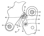
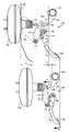
図1は、本発明が適用された常用ブレーキ用のブレーキペダル装置10を説明する図で、車両の左側から見た左側面図であり、図2は図1におけるII部の拡大図である。ブレーキペダル装置10は車両用ペダル装置に相当し、エンジンルームと車室内とを区切るダッシュパネル12には第1ペダルブラケット14が一体的に固定されており、操作ペダル18が略水平で且つ車両幅方向と略平行な第1支持軸20まわりの回動可能に配設されている。操作ペダル18は、上端部において第1支持軸20の軸心まわりに回動可能に支持されており、下端部に設けられた踏部22が車両前方側(図1の左方向)へ踏込み操作されるようになっている。
図1は、本発明が適用された常用ブレーキ用のブレーキペダル装置10を説明する図で、車両の左側から見た左側面図であり、図2は図1におけるII部の拡大図である。ブレーキペダル装置10は車両用ペダル装置に相当し、エンジンルームと車室内とを区切るダッシュパネル12には第1ペダルブラケット14が一体的に固定されており、操作ペダル18が略水平で且つ車両幅方向と略平行な第1支持軸20まわりの回動可能に配設されている。操作ペダル18は、上端部において第1支持軸20の軸心まわりに回動可能に支持されており、下端部に設けられた踏部22が車両前方側(図1の左方向)へ踏込み操作されるようになっている。
第1ペダルブラケット14にはまた、操作ペダル18よりも車両の前側に、第1支持軸20と平行な第2支持軸24まわりに回動可能に中間レバー26が配設されている。中間レバー26は、下端部において第2支持軸24の軸心まわりに回動可能に支持されて上方へ延び出しており、上下の中間位置で、連結リンク28を介して操作ペダル18に連結されている。中間レバー26の上端部には、ブレーキブースタ30のオペレーティングロッド32が連結されており、操作ペダル18の踏込み操作に連動して連結リンク28を介して機械的に第2支持軸24の左回り方向(出力方向)へ回動させられることにより、オペレーティングロッド32を前方へ押圧してブレーキ力を発生させる。ブレーキブースタ30はダッシュパネル12のエンジンルーム側に一体的に固設されており、オペレーティン
グロッド32は、そのダッシュパネル12から車室内へ突き出すように配設されている。オペレーティングロッド32は出力部材に相当する。
グロッド32は、そのダッシュパネル12から車室内へ突き出すように配設されている。オペレーティングロッド32は出力部材に相当する。
ダッシュパネル12よりも運転席側に位置するインパネリインフォースメント34には、第2ペダルブラケット36が一体的に固設されている。第2ペダルブラケット36は、第1支持軸20の両側部で前記第1ペダルブラケット14と重ね合わされ、ボルト等により共締めされており、互いに支え合うように一体的に連結されている。これにより、ペダルブラケットとして必要な所定の強度や剛性が確保されるようになっている。インパネリインフォースメント34は車体側部材に相当するもので、一般に、正面衝突時等の車両前方からの大荷重入力時に運転席側すなわち車両後方側へ変位する可能性或いは変位量がダッシュパネル12よりも少ない。図1はペダルブラケット14、36を仮想線で示し、その内側の構造が分かるように示した図である。
前記連結リンク28は、その両端部においてそれぞれ第1支持軸20と平行な第1連結ピン40、第2連結ピン42を介して、操作ペダル18、中間レバー26に相対回動可能に連結されている。連結リンク28を仮想線で示した図2から明らかなように、操作ペダル18側の第1連結ピン40は、操作ペダル18の予め定められたリンク連結部位に設けられた連結穴44に、軸心まわりに回動可能に配設されている。また、中間レバー26側の第2連結ピン42は、中間レバー26のリンク連結部位に設けられたピン受け部46に着座させられているとともに、中間レバー26に一体的に固設された離脱防止部材48によってピン受け部46からの離脱が阻止されるようになっている。この第2連結ピン42が、連結リンク28を中間レバー26に連結する連結ピンで、離脱防止部材48は離脱防止部に相当する。
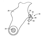
図3は、離脱防止部材48が固設された中間レバー26を単独で示した側面図で、図4は、その離脱防止部材48を単独で示した斜視図である。中間レバー26に設けられたピン受け部46は、連結リンク28を介して操作ペダル18の踏込み操作力が加えられる部分に設けられているとともに、その踏込み操作力を受け止めることができるように、第2連結ピン42の外周面と略等しい曲率の円弧形状を成している。これにより、踏込み操作力によって第2連結ピン42がピン受け部46に押圧されると、その第2連結ピン42はピン受け部46に安定して着座させられるように位置決めされ、踏込み操作力が確実にピン受け部46から中間レバー26に伝達される。
離脱防止部材48は金属板材を曲げ加工したもので、中間レバー26を跨ぐように断面U字形状を成しており、背部50から略平行に延び出すL字形状の一対の側壁52、54を備えている。一対の側壁52、54のL字形状の背部50側の一端部、すなわち図4において右上に位置する部分は、中間レバー26に固設される取付部56で、前記ピン受け部46の近傍において中間レバー26の両側面に密着するように重ね合わされ、溶接等により一体的に接合される。また、一対の側壁52、54のL字形状の他端部、すなわち図4において下方に位置して背部50から左方向へ突き出す部分は、前記ピン受け部46との間で第2連結ピン42を保持するストッパ部58で、第2連結ピン42の外周面と略等しい曲率の円弧が設けられている。このストッパ部58の先端と中間レバー26との間にはS(図2参照)が存在するが、この開口Sは第2連結ピン42の直径よりも小さく、第2連結ピン42はストッパ部58とピン受け部46との間に隙間が殆ど無い状態で回転可能に位置決めされて離脱不能に保持される。
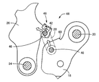
このように第2連結ピン42がストッパ部58とピン受け部46との間に保持されることにより、連結リンク28は第2連結ピン42を介して中間レバー26に連結され、通常の操作ペダル18の踏込み操作時および踏込み解除時には、それ等の操作ペダル18および中間レバー26は連動してそれぞれ第1支持軸20、第2支持軸24の軸心まわりに回動させられる。図5および図6は、操作ペダル18が踏込み操作された状態で、中間レバー26は操作ペダル18の踏込み操作に連動して連結リンク28を介して第2支持軸24の左回り方向へ回動させられる。また、この時の踏込み操作力は、図6に白抜き矢印で示すように、第1連結ピン40から連結リンク28を介して第2連結ピン42に伝達され、その第2連結ピン42からピン受け部46を介して確実に中間レバー26に伝達される。図6は図5におけるVI部の拡大図で、前記図2に対応する側面図である。
一方、図7および図8に示すように、車両の正面衝突時にブレーキブースタ30等と共にダッシュパネル12が後退変位させられると、そのダッシュパネル12とインパネリインフォースメント34とに跨がって配設されているペダルブラケット14、36は、インパネリインフォースメント34の後退変位量がダッシュパネル12よりも少ないことから、主に第1ペダルブラケット14のダッシュパネル12に近い部分が座屈変形させられる。このため、第1支持軸20および第2支持軸24の後退変位量はインパネリインフォースメント34と同様に比較的小さく、オペレーティングロッド32がダッシュパネル12と共に後退変位させられることにより、中間レバー26が初期位置から出力方向と逆方向、すなわち図7、図8において第2支持軸24の右まわり方向へ回動させられ、それに伴って操作ペダル18も第1支持軸20の左まわり方向へ回動させられて踏部22が運転席側へ後退させられる。図8は図7におけるVIII部の拡大図で、前記図2に対応する側面図である。
ここで、本実施例では中間レバー26が初期位置から逆方向へ回動させられた場合に、操作ペダル18との相対回動に基づいて、その操作ペダル18に一体に設けられた当接部60が前記離脱防止部材48に当接させられ、その離脱防止部材48を変形させ、場合によっては破断させて第2連結ピン42をピン受け部46から離脱させるようになっている。当接部60は三角形状の突起で、離脱防止部材48はその当接部60に押圧されることによって図9に示すように変形させられ、前記開口Sが寸法aだけ拡大されることにより、第2連結ピン42の離脱が許容される。図8に二点鎖線で示す連結リンク28は、第2連結ピン42がピン受け部46から離脱させられることにより、第1支持軸40まわりに下方へ回動させられた状態である。離脱防止部材48には、背部50の中間部分であって中間レバー26に固設される取付部56の近傍部分に、その背部50側からV字状に押圧変形させられたV字溝状のクラッシュビード62が設けられているとともに、そのクラッシュビード62と反対側、すなわち前記ストッパ部58に設けられた円弧の端部には、背部50側へ向かってスリット(U字状切欠)64が形成されている。そして、それ等のクラッシュビード62およびスリット64が設けられた部分が脆弱部として機能し、その脆弱部を起点として曲げ変形させられ、場合によってはクラッシュビード62およびスリット64を結んだ破断線66付近で破断する。図9の実線は変形後の形状で、一点鎖線は初期形状である。
中間レバー26は、第2支持軸24が支点、オペレーティングロッド32との連結部が力点、当接部60に押圧される離脱防止部材48が作用点として機能し、その作用点の押圧力F1は、力点に加えられた入力f1がてこの原理で増幅される。本実施例では作用点から力点までの距離よりも作用点から支点までの距離の方が短く、支点から作用点までの寸法をr1、支点から力点までの寸法をR1とすると、寸法r1はR1の半分以下で、それ等のレバー比(R1/r1)に応じて押圧力F1が増幅される。この押圧力F1に基づいて、離脱防止部材48が確実に曲げ変形させられ、場合によっては破断される。
このように離脱防止部材48の曲げ変形乃至は破断により第2連結ピン42がピン受け部46から離脱させられると、連結リンク28による操作ペダル18と中間レバー26との連結が解除され、中間レバー26の逆方向への回動に拘らず操作ペダル18の逆方向の回動や踏部22の後退が抑制される。すなわち、操作ペダル18は、中間レバー26の挙動と無関係に第1支持軸20まわりに回動できるようになり、自重によって下方へ垂下させられる。本実施例では、中間レバー26に設けられたピン受け部46、離脱防止部材48、操作ペダル18に設けられた当接部60等によって後退防止装置68が構成されている。
このような本実施例のブレーキペダル装置10においては、車両衝突時等にダッシュパネル12が後退変位させられた際に、中間レバー26が初期位置から逆方向へ回動させられると、離脱防止部材48が操作ペダル18の当接部60に当接して押圧されることにより曲げ変形させられ、場合によっては破断されて、第2連結ピン42がピン受け部46から離脱させられる。これにより、連結リンク28による操作ペダル18と中間レバー26との連結が解除され、中間レバー26の逆方向への回動に拘らず操作ペダル18の運転席側への回動が抑制されて、踏部22の後退を抑制する後退防止作用が安定して得られるようになる。
また、車両衝突時等にダッシュパネル12が後退変位させられた際に、中間レバー26の逆方向への回動に伴う操作ペダル18との相対回動に基づいて離脱防止部材48が曲げ変形させられ、場合によっては破断されることにより、第2連結ピン42がピン受け部46から離脱することが許容されるため、インパネリインフォースメント34との位置関係を考慮する必要がなく、ペダルブラケット14、36に組み付けられる操作ペダルアッシーのみで後退防止作用を実現することが可能で、設計の自由度が高いとともに設計変更などが容易で安価に構成できる。具体的には、インパネリインフォースメント34に固定される第2ペダルブラケット36を交換するだけで種々の車両に適用できる。
また、本実施例では離脱防止部として、中間レバー26と別体に構成されている離脱防止部材48が用いられており、操作ペダル18の当接部60に当接させられて押圧されることにより、クラッシュビード62およびスリット64が設けられた脆弱部が曲げ変形させられ、場合によっては破断させられて、ピン受け部46から第2連結ピン42が離脱することを許容するため、中間レバー26に離脱防止部を一体に形成する場合に比較して、当接部60との当接に伴って第2連結ピン42をピン受け部46から離脱させるための脆弱部等の設計の自由度や材質の選択の自由度が高く、各種の車両用ペダル装置に対して容易に適用できる。
以上、本発明の実施例を図面に基づいて詳細に説明したが、これはあくまでも一実施形態であり、本発明は当業者の知識に基づいて種々の変更、改良を加えた態様で実施することができる。
10:ブレーキペダル装置(車両用ペダル装置) 12:ダッシュパネル 14:第1ペダルブラケット 18:操作ペダル 20:第1支持軸 22:踏部 24:第2支持軸 26:中間レバー 28:連結リンク 32:オペレーティングロッド(出力部材) 34:インパネリインフォースメント(車体側部材) 36:第2ペダルブラケット 42:第2連結ピン(連結ピン) 46:ピン受け部 48:離脱防止部材(離脱防止部) 56:取付部 58:ストッパ部 60:当接部 62:クラッシュビード(脆弱部) 64:スリット(脆弱部) 68:後退防止装置
Claims (2)
- ダッシュパネルと、正面衝突時に車両後方側へ変位する変位量が該ダッシュパネルよりも小さい可能性が高い車体側部材と、に跨がって配設されているペダルブラケットと、
該ペダルブラケットに第1支持軸の軸心まわりに回動可能に配設され、下端部に設けられた踏部が車両前方側へ踏込み操作される操作ペダルと、
前記ペダルブラケットに前記第1支持軸と平行な第2支持軸の軸心まわりに回動可能に配設されるとともに、連結リンクを介して前記操作ペダルに連結され、該操作ペダルの踏込み操作に連動して機械的に出力方向へ回動させられることにより、所定の出力部材を車両前側へ変位させる中間レバーと、
を有する車両用ペダル装置に関し、前記ダッシュパネルが運転席側へ後退変位した時に前記操作ペダルの踏部が該運転席側へ後退することを抑制する後退防止装置において、
前記中間レバーには連結ピンを介して前記連結リンクが連結される連結部位にピン受け部が設けられ、該連結ピンが該ピン受け部に着座させられて、前記操作ペダルの踏込み操作力が該連結ピンから該ピン受け部を介して該中間レバーに伝達されるとともに、
該ピン受け部が設けられた前記連結部位には、前記連結ピンの離脱を阻止して連結状態を維持する離脱防止部が設けられている一方、
前記操作ペダルには、前記中間レバーが初期位置から前記出力方向と逆方向へ回動させられた場合に、該中間レバーおよび該操作ペダルの相対回動に基づいて前記離脱防止部に当接させられ、該離脱防止部を変形、破断、変位、または脱落させて前記連結ピンを前記ピン受け部から離脱させる当接部が設けられている
ことを特徴とする車両用ペダル装置の後退防止装置。 - 前記離脱防止部は、前記中間レバーと別体に構成されている別部材で、前記ピン受け部との間で前記連結ピンを保持するストッパ部と、前記中間レバーに一体的に取り付けられる取付部と、前記当接部に当接させられた際に変形乃至は破断させられて前記ストッパ部を前記ピン受け部から離間させて前記連結ピンの離脱を許容する脆弱部と、を一体に備えている離脱防止部材である
ことを特徴とする請求項1に記載の車両用ペダル装置の後退防止装置。
Applications Claiming Priority (2)
| Application Number | Priority Date | Filing Date | Title |
|---|---|---|---|
| JP2014-122877 | 2014-06-13 | ||
| JP2014122877A JP6144648B2 (ja) | 2014-06-13 | 2014-06-13 | 車両用ペダル装置の後退防止装置 |
Publications (1)
| Publication Number | Publication Date |
|---|---|
| WO2015190245A1 true WO2015190245A1 (ja) | 2015-12-17 |
Family
ID=54833350
Family Applications (1)
| Application Number | Title | Priority Date | Filing Date |
|---|---|---|---|
| PCT/JP2015/064383 Ceased WO2015190245A1 (ja) | 2014-06-13 | 2015-05-19 | 車両用ペダル装置の後退防止装置 |
Country Status (2)
| Country | Link |
|---|---|
| JP (1) | JP6144648B2 (ja) |
| WO (1) | WO2015190245A1 (ja) |
Families Citing this family (1)
| Publication number | Priority date | Publication date | Assignee | Title |
|---|---|---|---|---|
| JP7084815B2 (ja) | 2018-07-30 | 2022-06-15 | 株式会社アルファ | インサイドハンドル装置 |
Citations (4)
| Publication number | Priority date | Publication date | Assignee | Title |
|---|---|---|---|---|
| JPH10236335A (ja) * | 1997-02-25 | 1998-09-08 | Toyota Motor Corp | 車両用離脱部構造 |
| EP1074445A2 (en) * | 1999-07-09 | 2001-02-07 | FIAT AUTO S.p.A. | System to disengage the brake pedal in case of collision |
| JP2004334889A (ja) * | 2003-05-08 | 2004-11-25 | Ksr Automotive Ltd | 自動車のフロントペダルのリリースを可能にする装置、並びにこの装置を備えた自動車 |
| JP2006103501A (ja) * | 2004-10-05 | 2006-04-20 | Toyoda Iron Works Co Ltd | 車両用ペダルの後退防止装置 |
-
2014
- 2014-06-13 JP JP2014122877A patent/JP6144648B2/ja not_active Expired - Fee Related
-
2015
- 2015-05-19 WO PCT/JP2015/064383 patent/WO2015190245A1/ja not_active Ceased
Patent Citations (4)
| Publication number | Priority date | Publication date | Assignee | Title |
|---|---|---|---|---|
| JPH10236335A (ja) * | 1997-02-25 | 1998-09-08 | Toyota Motor Corp | 車両用離脱部構造 |
| EP1074445A2 (en) * | 1999-07-09 | 2001-02-07 | FIAT AUTO S.p.A. | System to disengage the brake pedal in case of collision |
| JP2004334889A (ja) * | 2003-05-08 | 2004-11-25 | Ksr Automotive Ltd | 自動車のフロントペダルのリリースを可能にする装置、並びにこの装置を備えた自動車 |
| JP2006103501A (ja) * | 2004-10-05 | 2006-04-20 | Toyoda Iron Works Co Ltd | 車両用ペダルの後退防止装置 |
Also Published As
| Publication number | Publication date |
|---|---|
| JP2016004334A (ja) | 2016-01-12 |
| JP6144648B2 (ja) | 2017-06-07 |
Similar Documents
| Publication | Publication Date | Title |
|---|---|---|
| US9981638B2 (en) | Vehicle pedal device | |
| US9821777B2 (en) | Vehicle brake pedal device | |
| JP4500739B2 (ja) | 車両用ペダルの後退防止装置 | |
| US11794704B2 (en) | Vehicular operation pedal device | |
| JP2008090381A (ja) | 自動車の操作ペダル装置 | |
| JP5306937B2 (ja) | 自動車のブレーキペダル装置 | |
| JP6144648B2 (ja) | 車両用ペダル装置の後退防止装置 | |
| JP6148629B2 (ja) | 車両用ペダル装置の後退防止装置 | |
| JP2006103501A (ja) | 車両用ペダルの後退防止装置 | |
| JP6144636B2 (ja) | 車両用ペダル装置の後退防止装置 | |
| JP6189347B2 (ja) | 車両用ペダル装置の後退防止装置 | |
| JP6403284B2 (ja) | 車両用ペダル装置の後退防止装置 | |
| WO2020012696A1 (ja) | 車両用操作ペダル装置 | |
| JP2018200516A (ja) | 車両用操作ペダル装置 | |
| JP6280083B2 (ja) | 車両用ペダル装置の後退防止装置 | |
| JP2014186369A (ja) | ブレーキペダル装置 | |
| JP2020030561A (ja) | 車両用操作ペダル装置 | |
| JP6920258B2 (ja) | 車両用操作ペダル装置 | |
| JP2012058801A (ja) | 車両のペダル装置 | |
| JP6190353B2 (ja) | 車両用ペダル装置の後退防止装置 | |
| JP6352229B2 (ja) | 車両用ペダル装置の後退防止装置 | |
| WO2023238787A1 (ja) | 車両用操作ペダル装置 | |
| WO2016157945A1 (ja) | 車両用ペダル装置の後退防止装置 | |
| JP2017215899A (ja) | 車両用ペダル装置の後退防止装置 | |
| JP2017211899A (ja) | 車両用ペダル装置の後退防止装置 |
Legal Events
| Date | Code | Title | Description |
|---|---|---|---|
| 121 | Ep: the epo has been informed by wipo that ep was designated in this application |
Ref document number: 15807111 Country of ref document: EP Kind code of ref document: A1 |
|
| NENP | Non-entry into the national phase |
Ref country code: DE |
|
| 122 | Ep: pct application non-entry in european phase |
Ref document number: 15807111 Country of ref document: EP Kind code of ref document: A1 |