WO2015190103A1 - 角速度センサ - Google Patents
角速度センサ Download PDFInfo
- Publication number
- WO2015190103A1 WO2015190103A1 PCT/JP2015/002918 JP2015002918W WO2015190103A1 WO 2015190103 A1 WO2015190103 A1 WO 2015190103A1 JP 2015002918 W JP2015002918 W JP 2015002918W WO 2015190103 A1 WO2015190103 A1 WO 2015190103A1
- Authority
- WO
- WIPO (PCT)
- Prior art keywords
- vibrating piece
- resonance frequency
- angular velocity
- mode
- vibrating
- Prior art date
- Legal status (The legal status is an assumption and is not a legal conclusion. Google has not performed a legal analysis and makes no representation as to the accuracy of the status listed.)
- Ceased
Links
Images


Classifications
-
- G—PHYSICS
- G01—MEASURING; TESTING
- G01C—MEASURING DISTANCES, LEVELS OR BEARINGS; SURVEYING; NAVIGATION; GYROSCOPIC INSTRUMENTS; PHOTOGRAMMETRY OR VIDEOGRAMMETRY
- G01C19/00—Gyroscopes; Turn-sensitive devices using vibrating masses; Turn-sensitive devices without moving masses; Measuring angular rate using gyroscopic effects
- G01C19/56—Turn-sensitive devices using vibrating masses, e.g. vibratory angular rate sensors based on Coriolis forces
- G01C19/5607—Turn-sensitive devices using vibrating masses, e.g. vibratory angular rate sensors based on Coriolis forces using vibrating tuning forks
-
- G—PHYSICS
- G01—MEASURING; TESTING
- G01C—MEASURING DISTANCES, LEVELS OR BEARINGS; SURVEYING; NAVIGATION; GYROSCOPIC INSTRUMENTS; PHOTOGRAMMETRY OR VIDEOGRAMMETRY
- G01C19/00—Gyroscopes; Turn-sensitive devices using vibrating masses; Turn-sensitive devices without moving masses; Measuring angular rate using gyroscopic effects
- G01C19/56—Turn-sensitive devices using vibrating masses, e.g. vibratory angular rate sensors based on Coriolis forces
- G01C19/5642—Turn-sensitive devices using vibrating masses, e.g. vibratory angular rate sensors based on Coriolis forces using vibrating bars or beams
- G01C19/5656—Turn-sensitive devices using vibrating masses, e.g. vibratory angular rate sensors based on Coriolis forces using vibrating bars or beams the devices involving a micromechanical structure
-
- H—ELECTRICITY
- H10—SEMICONDUCTOR DEVICES; ELECTRIC SOLID-STATE DEVICES NOT OTHERWISE PROVIDED FOR
- H10N—ELECTRIC SOLID-STATE DEVICES NOT OTHERWISE PROVIDED FOR
- H10N30/00—Piezoelectric or electrostrictive devices
- H10N30/30—Piezoelectric or electrostrictive devices with mechanical input and electrical output, e.g. functioning as generators or sensors
- H10N30/302—Sensors
Definitions
- This disclosure relates to an angular velocity sensor having a vibrating body.
- an angular velocity sensor having a vibrating body having a vibrating piece fixed to the base has been proposed (for example, see Patent Document 1).
- this angular velocity sensor is configured using a substrate made of a piezoelectric material, and a vibrating body and an outer peripheral portion surrounding the vibrating body are partitioned on the substrate.
- the vibrating body is supported on the outer periphery via a plurality of beam portions.
- the beam part arranged between the vibrating body (base) and the outer peripheral part it is possible to suppress the transmission of disturbances such as vibration and impact from the outer peripheral part to the vibrating body, and the detection accuracy is lowered. This can be suppressed.
- each beam portion is independently connected to the outer peripheral portion. For this reason, the effect of suppressing disturbance differs depending on each beam part, and it may not be possible to sufficiently suppress a decrease in detection accuracy.
- This indication aims at providing the angular velocity sensor which can control that detection accuracy falls in view of the above-mentioned point.
- the angular velocity sensor includes a substrate configured using a piezoelectric material, a vibrating body formed on the substrate, and having a first vibrating piece and a second vibrating piece that vibrate in a surface direction of the substrate. And an outer peripheral portion formed on the substrate and arranged around the vibrating body, and when an angular velocity is applied in a state where the vibrating body is vibrated, an electric charge corresponding to the angular velocity is generated.
- the vibrating body is displaceable at least in the first direction when one direction in the surface direction of the substrate is a first direction and a direction orthogonal to the first direction of the surface directions of the substrate is a second direction.
- a plurality of beam portions supported on the outer periphery via a plurality of beam portions having one beam component member and a second beam component member coupled to the first beam component member and displaceable in at least the second direction. At least a part of the beam component members on the outer peripheral portion side of the first beam component member and the second beam component member are integrated with each other.
- the displacement is coupled to each other, so that the disturbance is further prevented from being transmitted from the outer peripheral part to the vibrating body. It can suppress and it can suppress that detection accuracy falls.
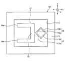
- FIG. 1 is a plan view of an angular velocity sensor according to a first embodiment of the present disclosure.
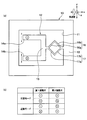
- A) of FIG. 2 is a figure which shows the action
- (b) of FIG. 2 is a figure which shows the pattern of the action
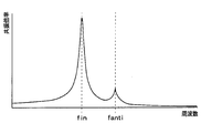
- FIG. 3 is a diagram showing a frequency characteristic (response curve) of a resonance magnification of a general angular velocity sensor, FIG.
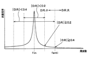
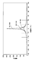
- FIG. 4 is a diagram illustrating a frequency characteristic (response curve) of the resonance magnification of the angular velocity sensor of the first embodiment.
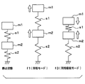
- FIG. 5 is a schematic diagram showing the movement of the common mode and the common mode absorption mode with respect to a stationary state
- FIG. 7 is a graph of Formula 1 when the Q value is changed.
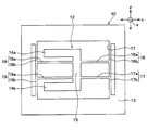
- FIG. 8 is a plan view of an angular velocity sensor according to the second embodiment of the present disclosure.
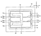
- FIG. 9 is a plan view of an angular velocity sensor according to the third embodiment of the present disclosure.
- angular velocity sensor of the present embodiment is preferably applied to a device that detects an angular velocity applied to the vehicle.
- the angular velocity sensor includes a substrate 10 made of quartz or PZT (zircon lead titanate) as a piezoelectric material.
- the substrate 10 is subjected to well-known micromachining to form a groove portion 11, and the vibrating body 12 and the outer peripheral portion 13 are partitioned by the groove portion 11.
- the outer peripheral portion 13 is partitioned from the vibrating body 12 so as to be positioned around the vibrating body 12.
- the first vibrating piece 14a and the second vibrating piece 14b are held by the base 15.
- the base 15 has a planar rectangular shape having a longitudinal direction (up and down direction in FIG. 1).
- the first vibrating piece 14a and the second vibrating piece 14b are arranged so as to protrude in the same direction at both ends of the base portion 15 in the longitudinal direction. That is, the vibrating body 12 of the present embodiment is a so-called tuning fork type.
- a drive electrode and a detection electrode are formed on each of the vibration pieces 14a and 14b.
- a drive electrode is formed on the base 15 side of each vibrating piece 14a and 14b
- a detection electrode is formed on the side opposite to the base 15 side of each vibrating piece 14a and 14b.
- the vibrating body 12 is supported by the outer peripheral portion 13 via the first beam portion 16 and the second beam portion 17.
- the projecting direction of the first vibrating piece 14a and the second vibrating piece 14b with respect to the base 15 is the x-axis direction
- the direction orthogonal to the projecting direction in the plane of the substrate 10 is the first vibration piece 14a and the second vibration piece 14b
- the first vibration piece 14a and the second vibration piece 14b are arranged in the y-axis direction
- the normal direction to the surface direction of the substrate 10 is the z-axis direction.
- the y-axis direction corresponds to the first direction
- the x-axis direction corresponds to the second direction
- the z-axis direction corresponds to the third direction.
- the first beam portion 16 includes a first beam component member 16a and a second beam component member 16b that are inclined with respect to the x-axis direction and the y-axis direction.
- the first beam portion 16 is composed of a first beam constituent member 16a and a second beam constituent member 16b that are displaceable in the x-axis direction and the y-axis direction.
- the first beam constituent member 16a is disposed on the vibrating body 12 side
- the second beam constituent member 16b is disposed on the outer peripheral portion 13 side.
- the first beam constituent member 16a and the second beam It is made into the substantially V shape with which the structural member 16b was connected.
- the 2nd beam part 17 is comprised by the 1st beam structural member 17a and the 2nd beam structural member 17b which inclined with respect to the x-axis direction and the y-axis direction.
- the second beam portion 17 includes a first beam component member 17a and a second beam component member 17b that can be displaced in the x-axis direction and the y-axis direction.
- the first beam constituent member 17a is arranged on the vibrating body 12 side and the second beam constituent member 17b is arranged on the outer peripheral portion 13 side, and the first beam constituent member 17a and the second beam It is made into the substantially V shape with which the structural member 17b was connected.
- the 2nd beam part 17 is made into the substantially V shape which has a convex part on the opposite side to the substantially V shape which the 1st beam part 16 comprises.
- the 1st beam part 16 and the 2nd beam part 17 are connected with the vibrating body 12 in the state which the edge part by the side of the vibrating body 12 in each 1st beam structural member 16a, 17a was connected and integrated. Moreover, the 1st beam part 16 and the 2nd beam part 17 are connected with the outer peripheral part 13 in the state which the edge part by the side of the outer peripheral part 13 in each 2nd beam structural member 16b, 17b was connected and integrated. . That is, in the present embodiment, the first beam portion 16 and the second beam portion 17 form a planar frame-shaped beam portion, and one set of two sets of corner portions of the frame-shaped beam portion facing each other. It can be said that the corner is connected to the vibrating body 12 and the outer peripheral portion 13.
- the first beam portion 16 and the second beam portion 17 have a cross-sectional area, a length, and the like as appropriate so that the spring constant is smaller than the spring constant of the first vibrating piece 14a and the second vibrating piece 14b. Has been adjusted.
- a drive signal is applied to the drive electrodes formed on the first vibrating piece 14a and the second vibrating piece 14b.
- the driving signals applied to the first vibrating piece 14a and the second vibrating piece 14b are pulsed driving signals having a predetermined amplitude and frequency, and have phases different from each other by 180 °.
- the first vibrating piece 14 a and the second vibrating piece 14 b drive and vibrate in opposite directions along the y-axis direction. In other words, the first vibrating piece 14a and the second vibrating piece 14b vibrate so as to open and close each other.
- the first vibrating piece 14a and the second vibrating piece 14b vibrate in the opposite direction in the z-axis direction due to the Coriolis force.
- the first vibrating piece 14a vibrates in the direction perpendicular to the middle sheet surface of FIG. 2A
- the second vibrating piece 14b vibrates to the front side in the perpendicular direction of the middle sheet surface of FIG.
- a charge corresponding to the vibration is generated on detection electrodes (not shown) formed on the first vibrating piece 14a and the second vibrating piece 14b.
- the angular velocity is detected by differentially amplifying the charge generated in each detection electrode.
- a symbol with a black circle in the circle indicates the other side in the vertical direction of the paper surface
- a symbol with a cross in the circle indicates the vertical direction of the paper surface. It shows that it vibrates to the near side.
- the vibrating body 12 is supported by the outer peripheral portion 13 via the first beam portion 16 and the second beam portion 17. For this reason, when the first beam portion 16 and the second beam portion 17 are displaced (bends) in the x-axis direction and the y-axis direction, disturbances such as vibration and impact are transmitted from the outer peripheral portion 13 to the vibrating body 12. This can be suppressed.
- the second beam constituent members 16b and 17b in the first beam portion 16 and the second beam portion 17 are integrated. For this reason, since the 1st beam part 16 and the 2nd beam part 17 mutually couple
- FIG. 1st beam part 16 and the 2nd beam part 17 mutually couple
- the angular velocity is detected based on the detection principle as described above, but the first vibrating piece 14a and the second vibrating piece 14b are mutually in resonance with the resonance frequency fin of the common mode that vibrates in the same direction in the z-axis direction. It has a resonance frequency fanti of a reverse phase mode that vibrates in the reverse direction.
- the common mode here means that the first vibrating piece 14a and the second vibrating piece 14b are moved in the z-axis direction when an impact along the z-axis direction is applied. It means that it can be vibrated in the same direction.
- the reverse phase mode here means that the first vibrating piece 14a and the second vibrating piece 14b are vibrated in the opposite directions in the z-axis direction when an impact along the z-axis direction is applied. ing.
- the detection electrodes formed on the first vibrating piece 14a and the second vibrating piece 14b By differential amplification (differential output) of the electric charges generated in, the electric charges (signals) resulting from the vibration based on the impact are canceled out.
- differential amplification differential output
- the first vibrating piece 14a and the second vibrating piece 14b change in the anti-phase mode
- charges (signals) resulting from the vibration based on the impact are caused by differential amplification. It is not canceled out, and becomes an output error, and the detection accuracy decreases.
- the resonance magnification (response strength) changes according to the frequency component included in the impact.
- the frequency characteristic (response curve) of the resonance magnification is as shown in FIG. 3 at the resonance frequency fin of the common mode.
- the resonance magnification is the largest.
- the resonance magnification rapidly decreases in other frequency regions centering on the resonance frequency fin of the common mode, and decreases as the distance from the resonance frequency fin of the common mode decreases.
- the resonance frequency fanti of the anti-phase mode exists separately from the resonance frequency fin of the common mode, and the resonance frequency fanti of the anti-phase mode is sufficiently smaller than the resonance frequency fin of the common mode, but the resonance magnification is increased to some extent. Then, the resonance frequency fanti component of the antiphase mode included in the impact induces a movement that vibrates the first vibrating piece 14a and the second vibrating piece 14b in the reverse direction, and generates an output error.
- the resonance magnification at the resonance frequency fanti increases as the resonance frequency fanti is closer to the resonance frequency fin of the in-phase mode. That is, as shown in FIG. 3, the resonance magnification is attenuated centering on the resonance frequency fin of the common mode.
- the resonance frequency fanti of the anti-phase mode is too close to the resonance frequency fin of the common mode, the resonance frequency fanti component of the anti-phase mode included in the impact exists in a region where it is not sufficiently attenuated when an impact is applied. become. For this reason, the resonance frequency fanti component of the non-damped anti-phase mode in the shock induces the anti-phase mode motion in this vibration.
- the resonance frequency fanti component of the anti-phase mode included in the impact can be made a sufficiently attenuated region, It can be said that the induction of movement can be suppressed.
- the frequency characteristic of the resonance magnification can be adjusted based on the setting of the first vibrating piece 14a and the second vibrating piece 14b in the case of the spring that allows displacement in the z-axis direction, that is, in the case of this embodiment. As shown in FIG. 4, when the resonance frequency fanti in the anti-phase mode is separated from the resonance frequency fin in the in-phase mode, the resonance magnification at the resonance frequency fanti in the anti-phase mode can be reduced.
- a value obtained by dividing the difference between the resonance frequency fanti of the antiphase mode and the resonance frequency fin of the common mode by the resonance frequency fanti of the antiphase mode is a decoupling ratio (Decoupling Ratio).
- the absolute value of DR is 0.2 or more
- the resonance magnification is 1 regardless of whether the peak value (Q value: resonance magnification at the resonance frequency fin) is large or small. It can be set to a region where robustness can be ensured with an error of about 30%, and preferably when the absolute value of DR is 0.4 or more, the resonance magnification at the resonance frequency fanti in the antiphase mode is set to 1 or less.
- the resonance frequency fanti component of the anti-phase mode included in the impact is more sufficiently attenuated, and the induction of the anti-phase mode motion can be suppressed.
- Hz if the resonance frequency fanti reverse phase mode and 16 kHz, D. R. absolute value of. Becomes 0.4 or more, so that the resonance magnification becomes 1 or less.
- the absolute value of D.R. is 0.2 or more, preferably 0.4 or more.
- such an angular velocity sensor has two resonance mode frequencies f1 and f3 with respect to application of an impact in a direction along the y-axis direction.
- the two weights m1, m2 is the resonance frequency f3 of the in-phase absorption mode in which vibration is performed in the opposite direction.
- the spring s2 is constituted by the first beam portion 16 and the second beam portion 17
- the weight m2 is constituted by the base portion 15
- the spring s1 is constituted by the first vibrating piece 14a and the second vibrating piece 14b.
- the weight m1 is composed of the first vibrating piece 14a and the second vibrating piece 14b.
- the resonance frequency f3 of the common-mode absorption mode is higher than the resonance frequency f1 of the common-mode mode.
- the first vibrating piece 14a, the second vibrating piece 14b, and the base 15 are (1) vibration excited by non-resonance, (2) vibration excitation by resonance, (3) It is vibrated by a displacement mechanism by adding three vibration excitations by resonance interference. That is, the first vibrating piece 14a, the second vibrating piece 14b, and the base portion 15 are displaced (vibrated) by generating the vibration excitations (1) to (3) so as to be added together.
- Vibration excitation due to non-resonance is simply a displacement amount calculated from inertial force and spring force. Further, (2) vibration excitation by resonance is performed by applying an impact component having the same frequency as the resonance frequency f1 of the angular velocity sensor, mainly the in-phase resonance frequency f1, and the Q value specific to the vibrating body 12 (peak value of resonance magnification). The amount of excitation calculated from Then, (3) vibration excitation by resonance interference is an excitation amount by interference at an integral multiple (n times) of the resonance frequency f1 of the common mode and the resonance frequency f3 of the common mode absorption mode.
- f1 represents the resonance frequency f1 of the common mode
- f3 represents the resonance frequency f3 of the common mode absorption mode
- n represents an integer
- Q represents the Q value.
- FIG. 7 is a graph of Equation 1 with the Q value changed.
- the avoidance difference D in FIG. 7 indicates the degree to which the absolute value ⁇ f3 of the difference between the resonance frequency f3 of the common mode absorption mode and the value n times the resonance frequency f1 of the common mode is deviated from the resonance frequency f1 of the common mode. Yes.
- the avoidance difference D 0, that is, when the absolute value ⁇ f3 coincides with the resonance frequency f1 of the common mode, the amplification factor A becomes the largest.
- (3) vibration excitation due to resonance interference appears as the largest peak value, and the contribution ratio in the total vibration excitation becomes high.
- the avoidance difference D is designed to be larger than 5% (D> 5%)
- the first term in the root of the denominator in Equation 1 is sufficiently larger than the second term
- the second term The amplification factor A can be determined regardless of the Q value included in the. Specifically, as shown in FIG. 7, the amplification factor A decreases to about 20.
- the amplification factor A can be set regardless of the Q value, and the amplification factor A can be made sufficiently small, so that the robustness can be improved.
- Absolute value ⁇ f3 satisfies the following condition. That is, at least the avoidance difference D is greater than 0% while the absolute value ⁇ f3 is greater than the value obtained by multiplying the resonance frequency f1 of the common mode by the avoidance difference D ( ⁇ f3> f1 ⁇ D).
- the amplification factor A can be reduced regardless of the Q value, and the robustness can be improved. More preferably, when the avoidance difference D> 10%, the amplification factor A can be reduced to almost one digit, and (3) vibration excitation due to resonance interference is (1) vibration excitation due to non-resonance or (2) It can be suppressed to a state sufficiently reduced to the same level as vibration excitation by resonance.
- Vibration excitation due to resonance interference can be reduced by designing the resonance frequency f1 of the common mode satisfying such a relationship and the resonance frequency f3 of the common mode absorption mode.
- the amplification factor A is defined by an integral multiple (n times) of the resonance frequency f1 of the common mode, the resonance frequency f3 of the common mode absorption mode, and the Q value.
- the amplification factor A can also be reduced by reducing the Q value.
- the Q value can be lowered by lowering the degree of vacuum at that time.
- the amplification factor A can be reduced, and (3) vibration excitation due to resonance interference can be reduced.
- the Q value is reduced, (2) vibration excitation due to resonance is also reduced, and (3) it is reduced together with vibration excitation due to resonance interference, and it is possible to further improve impact resistance performance. Become.
- the vibrating body 12 is supported by the outer peripheral portion 13 via the first beam portion 16 and the second beam portion 17. For this reason, when the first beam portion 16 and the second beam portion 17 are displaced (bends) in the x-axis direction and the y-axis direction, disturbances such as vibration and impact are transmitted from the outer peripheral portion 13 to the vibrating body 12. This can be suppressed.
- the second beam constituent members 16b and 17b in the first beam portion 16 and the second beam portion 17 are integrated. For this reason, since the first beam portion 16 and the second beam portion 17 are coupled to each other, the transmission of disturbance from the outer peripheral portion 13 to the vibrating body 12 can be further suppressed, and the detection accuracy is further reduced. This can be suppressed.
- the spring constants of the first beam portion 16 and the second beam portion 17 are smaller than the spring constants of the first vibrating piece 14a and the second vibrating piece 14b. For this reason, compared with the case where the spring constant of the 1st beam part 16 and the 2nd beam part 17 is made larger than the spring constant which the 1st vibration piece 14a and the 2nd vibration piece 14b have, it is a vibrating body from the outer peripheral part 13. Transmission of disturbance to 12 can be suppressed.
- the absolute value of D.R. is 0.2 or more. For this reason, even if an impact in the z-axis direction is applied to the angular velocity sensor, it is possible to suppress the induction of the motion in the reverse phase mode. For this reason, generation
- the absolute value ⁇ f3 is greater than the value obtained by multiplying the resonance frequency f1 in the common mode by the avoidance difference D ( ⁇ f3> f1 ⁇ D), and at least the avoidance difference D is greater than 0%. growing. For this reason, it can suppress that the vibration excitation by resonance interference becomes the maximum displacement, and can improve impact resistance performance.
- the vibrating body 12 is opposite to the first beam portion 16 and the second beam portion 17 with the vibrating body 12 sandwiched between the first beam portion 16 and the second beam portion 17. It is supported by the outer peripheral part 13 through the 3rd, 4th beam parts 18 and 19 arrange
- the first beam portion 16 and the second beam portions 16, 17 are connected to the first beam constituent members 16a, 17a extending in the x-axis direction and the first beam constituent members 16a, 17a, and the second beam extending in the y-axis direction. It has structural members 16b and 17b. That is, the first beam portion 16 and the second beam portion 17 include first beam constituent members 16a and 17a that are displaceable in the y-axis direction, and second beam constituent members 16b that are displaceable in the x-axis direction. 17b. And the 2nd beam structural member 16b of the 1st beam part 16 and the 2nd beam structural member 17b of the 2nd beam part 17 are integrated.
- the third and fourth beam portions 18, 19 are connected to the first beam constituent members 18a, 19a extending in the x-axis direction and the first beam constituent members 18a, 19a, and the second beam extending in the y-axis direction. It has structural members 18b and 19b. That is, the third and fourth beam portions 18 and 19 are first beam constituent members 18a and 19a that are displaceable in the y-axis direction, and second beam constituent members 18b and 19b that are displaceable in the x-axis direction. And have. And the 2nd beam structural member 18b of the 3rd beam part 18 and the 2nd beam structural member 19b of the 4th beam part 19 are integrated.
- first to fourth beam portions 16 to 19 may be provided, and the first and second beam constituting members 16a to 19b may be displaced only in one direction. Also in such an angular velocity sensor, the second beam constituent members 16b and 17b of the first beam portion 16 and the second beam portion 17 are integrated, and the second beam constituent members 18b of the third and fourth beam portions 18 and 19 are integrated. , 19b are integrated, the same effect as in the first embodiment can be obtained.
- a frame portion 20 surrounding the vibration body 12 is formed between the vibration body 12 and the outer peripheral portion 13, and the frame portion 20 includes a plurality of support portions 21. It is supported by the outer peripheral part 13 via.
- the first beam constituting members 16a to 19a are respectively connected to the frame portion 20, and the second beam constituting members 16b to 19b are constituted by the frame portion 20. That is, the second beam constituent members 16b to 19b in the first to fourth beam portions 16 to 19 are all integrated.
- the first to fourth beam portions 16 to 19 further suppress the transmission of disturbance from the outer peripheral portion 13 to the vibrating body 12 because all the displacements of the beam portions 16 to 19 are coupled to each other.
- the same effect as the second embodiment can be obtained.
- the frame portion 20 (the second beam constituent members 16b to 19b in the first to fourth beam portions 16 to 19) is supported by the outer peripheral portion 13 via the plurality of support portions 21 has been described.
- the frame portion 20 may be supported by the outer peripheral portion 13 through only one support portion 21.
- the configuration of the vibrating body 12 may be changed.
- the vibrating body 12 may be a so-called H-type tuning fork in which the first vibrating piece 14 a and the second vibrating piece 14 b protrude in both directions with respect to the base portion 15.
- the vibrating body 12 is a so-called tripod tuning fork having a detection piece protruding in the same direction as the first vibrating piece 14a and the second vibrating piece 14b between the first vibrating piece 14a and the second vibrating piece 14b. Also good.
- the first vibrating piece 14a and the second vibrating piece 14b serve as driving pieces, and the angular velocity is detected based on the electric charge generated in the detecting piece.
- the angular velocity is detected based on the charge generated in the detection piece. That is, the angular velocity is detected without performing differential amplification.
- the vibrating body 12 may be a so-called double T-type tuning fork in which the first vibrating piece 14a, the second vibrating piece 14b, and the detection piece protrude from the base 15 on both sides.
- the end portions on the base 15 side in the first beam constituting members 16a and 17a may not be integrated, and may be provided in the base 15 respectively.
- the spring constants of the beam portions 16 to 19 may be larger than the spring constants of the first vibrating piece 14a and the second vibrating piece 14b.
Landscapes
- Physics & Mathematics (AREA)
- Engineering & Computer Science (AREA)
- General Physics & Mathematics (AREA)
- Radar, Positioning & Navigation (AREA)
- Remote Sensing (AREA)
- Gyroscopes (AREA)
Priority Applications (3)
| Application Number | Priority Date | Filing Date | Title |
|---|---|---|---|
| CN201580031569.7A CN106662444B (zh) | 2014-06-13 | 2015-06-11 | 角速度传感器 |
| US15/311,547 US10060744B2 (en) | 2014-06-13 | 2015-06-11 | Angular velocity sensor |
| DE112015002805.6T DE112015002805T5 (de) | 2014-06-13 | 2015-06-11 | Winkelgeschwindigkeitssensor |
Applications Claiming Priority (2)
| Application Number | Priority Date | Filing Date | Title |
|---|---|---|---|
| JP2014-122512 | 2014-06-13 | ||
| JP2014122512A JP6256215B2 (ja) | 2014-06-13 | 2014-06-13 | 角速度センサ |
Publications (1)
| Publication Number | Publication Date |
|---|---|
| WO2015190103A1 true WO2015190103A1 (ja) | 2015-12-17 |
Family
ID=54833214
Family Applications (1)
| Application Number | Title | Priority Date | Filing Date |
|---|---|---|---|
| PCT/JP2015/002918 Ceased WO2015190103A1 (ja) | 2014-06-13 | 2015-06-11 | 角速度センサ |
Country Status (5)
| Country | Link |
|---|---|
| US (1) | US10060744B2 (enExample) |
| JP (1) | JP6256215B2 (enExample) |
| CN (1) | CN106662444B (enExample) |
| DE (1) | DE112015002805T5 (enExample) |
| WO (1) | WO2015190103A1 (enExample) |
Families Citing this family (1)
| Publication number | Priority date | Publication date | Assignee | Title |
|---|---|---|---|---|
| JP6639377B2 (ja) * | 2016-12-08 | 2020-02-05 | 株式会社東芝 | 振動装置 |
Citations (5)
| Publication number | Priority date | Publication date | Assignee | Title |
|---|---|---|---|---|
| JPH07294262A (ja) * | 1994-04-28 | 1995-11-10 | Murata Mfg Co Ltd | 角速度センサ |
| JP2011075415A (ja) * | 2009-09-30 | 2011-04-14 | Tdk Corp | 圧電振動デバイス |
| JP2013181856A (ja) * | 2012-03-02 | 2013-09-12 | Seiko Epson Corp | 振動片、振動デバイス、物理量検出装置、および電子機器 |
| JP2013210283A (ja) * | 2012-03-30 | 2013-10-10 | Denso Corp | ロールオーバージャイロセンサ |
| JP2014006238A (ja) * | 2012-05-29 | 2014-01-16 | Denso Corp | 物理量センサ |
Family Cites Families (9)
| Publication number | Priority date | Publication date | Assignee | Title |
|---|---|---|---|---|
| JP4415383B2 (ja) | 2005-01-24 | 2010-02-17 | セイコーエプソン株式会社 | 振動ジャイロ素子、振動ジャイロ素子の支持構造およびジャイロセンサ |
| CN101796374A (zh) * | 2007-09-03 | 2010-08-04 | 松下电器产业株式会社 | 惯性力传感器 |
| JP4626858B2 (ja) | 2008-03-31 | 2011-02-09 | Tdk株式会社 | 角速度センサ素子 |
| FR2969278B1 (fr) * | 2010-12-20 | 2013-07-05 | Onera (Off Nat Aerospatiale) | Structure planaire pour gyrometre tri-axe |
| JP5838695B2 (ja) * | 2011-09-29 | 2016-01-06 | セイコーエプソン株式会社 | センサー素子、センサー素子の製造方法、センサーデバイスおよび電子機器 |
| JP5923970B2 (ja) | 2011-12-23 | 2016-05-25 | 株式会社デンソー | 振動型角速度センサ |
| JP5974629B2 (ja) * | 2012-05-23 | 2016-08-23 | セイコーエプソン株式会社 | 振動片、振動片の製造方法、角速度センサー、電子機器、移動体 |
| JP2016085192A (ja) * | 2014-10-29 | 2016-05-19 | セイコーエプソン株式会社 | 振動素子、電子デバイス、電子機器および移動体 |
| JP2016085190A (ja) * | 2014-10-29 | 2016-05-19 | セイコーエプソン株式会社 | 振動素子、振動素子の製造方法、電子デバイス、電子機器、および移動体 |
-
2014
- 2014-06-13 JP JP2014122512A patent/JP6256215B2/ja not_active Expired - Fee Related
-
2015
- 2015-06-11 CN CN201580031569.7A patent/CN106662444B/zh not_active Expired - Fee Related
- 2015-06-11 US US15/311,547 patent/US10060744B2/en active Active
- 2015-06-11 DE DE112015002805.6T patent/DE112015002805T5/de not_active Withdrawn
- 2015-06-11 WO PCT/JP2015/002918 patent/WO2015190103A1/ja not_active Ceased
Patent Citations (5)
| Publication number | Priority date | Publication date | Assignee | Title |
|---|---|---|---|---|
| JPH07294262A (ja) * | 1994-04-28 | 1995-11-10 | Murata Mfg Co Ltd | 角速度センサ |
| JP2011075415A (ja) * | 2009-09-30 | 2011-04-14 | Tdk Corp | 圧電振動デバイス |
| JP2013181856A (ja) * | 2012-03-02 | 2013-09-12 | Seiko Epson Corp | 振動片、振動デバイス、物理量検出装置、および電子機器 |
| JP2013210283A (ja) * | 2012-03-30 | 2013-10-10 | Denso Corp | ロールオーバージャイロセンサ |
| JP2014006238A (ja) * | 2012-05-29 | 2014-01-16 | Denso Corp | 物理量センサ |
Also Published As
| Publication number | Publication date |
|---|---|
| CN106662444B (zh) | 2019-10-11 |
| JP6256215B2 (ja) | 2018-01-10 |
| US10060744B2 (en) | 2018-08-28 |
| JP2016003880A (ja) | 2016-01-12 |
| DE112015002805T5 (de) | 2017-03-02 |
| US20170108335A1 (en) | 2017-04-20 |
| CN106662444A (zh) | 2017-05-10 |
Similar Documents
| Publication | Publication Date | Title |
|---|---|---|
| JP4868027B2 (ja) | 加速度角速度センサ | |
| US8726731B2 (en) | Micromechanical structures | |
| CN104350359B (zh) | 物理量传感器 | |
| US9696158B2 (en) | Gyro sensor and composite sensor comprising gyro sensor | |
| JP6260706B2 (ja) | 改良された直交位相補正を有するジャイロスコープ構造体およびジャイロスコープ | |
| JP2012519295A (ja) | 角速度の振動微小機械センサ | |
| CN104422786A (zh) | 微机械传感器和用于制造微机械传感器的方法 | |
| JP5884603B2 (ja) | ロールオーバージャイロセンサ | |
| JP2012519295A5 (enExample) | ||
| JP6256215B2 (ja) | 角速度センサ | |
| WO2010041422A1 (ja) | 角速度センサ素子およびこれを用いた角速度センサと角速度センサユニット及びその信号検出方法 | |
| JP2008014727A (ja) | 加速度角速度センサ | |
| WO2018003692A1 (ja) | 物理量センサ | |
| JP5018337B2 (ja) | 音叉振動型センサ、力学量検出装置、及び力学量検出方法 | |
| JP2019020339A (ja) | 振動型角速度センサ | |
| JP4816273B2 (ja) | ジャイロセンサ | |
| JP2011047852A (ja) | 慣性センサ | |
| JP4262691B2 (ja) | 振動ジャイロ | |
| JP6189792B2 (ja) | 角速度センサ | |
| WO2016067543A1 (ja) | 振動型角速度センサ | |
| JP5471217B2 (ja) | 角速度センサユニットおよびその信号検出方法 | |
| JP2012163386A (ja) | 角速度センサユニットおよびその信号検出方法 | |
| WO2017204057A1 (ja) | ジャイロセンサ及び電子機器 |
Legal Events
| Date | Code | Title | Description |
|---|---|---|---|
| 121 | Ep: the epo has been informed by wipo that ep was designated in this application |
Ref document number: 15807382 Country of ref document: EP Kind code of ref document: A1 |
|
| WWE | Wipo information: entry into national phase |
Ref document number: 15311547 Country of ref document: US |
|
| WWE | Wipo information: entry into national phase |
Ref document number: 112015002805 Country of ref document: DE |
|
| 122 | Ep: pct application non-entry in european phase |
Ref document number: 15807382 Country of ref document: EP Kind code of ref document: A1 |