WO2015190103A1 - Angular velocity sensor - Google Patents
Angular velocity sensor Download PDFInfo
- Publication number
- WO2015190103A1 WO2015190103A1 PCT/JP2015/002918 JP2015002918W WO2015190103A1 WO 2015190103 A1 WO2015190103 A1 WO 2015190103A1 JP 2015002918 W JP2015002918 W JP 2015002918W WO 2015190103 A1 WO2015190103 A1 WO 2015190103A1
- Authority
- WO
- WIPO (PCT)
- Prior art keywords
- vibrating piece
- resonance frequency
- angular velocity
- mode
- vibrating
- Prior art date
Links
Images


Classifications
-
- G—PHYSICS
- G01—MEASURING; TESTING
- G01C—MEASURING DISTANCES, LEVELS OR BEARINGS; SURVEYING; NAVIGATION; GYROSCOPIC INSTRUMENTS; PHOTOGRAMMETRY OR VIDEOGRAMMETRY
- G01C19/00—Gyroscopes; Turn-sensitive devices using vibrating masses; Turn-sensitive devices without moving masses; Measuring angular rate using gyroscopic effects
- G01C19/56—Turn-sensitive devices using vibrating masses, e.g. vibratory angular rate sensors based on Coriolis forces
- G01C19/5607—Turn-sensitive devices using vibrating masses, e.g. vibratory angular rate sensors based on Coriolis forces using vibrating tuning forks
-
- G—PHYSICS
- G01—MEASURING; TESTING
- G01C—MEASURING DISTANCES, LEVELS OR BEARINGS; SURVEYING; NAVIGATION; GYROSCOPIC INSTRUMENTS; PHOTOGRAMMETRY OR VIDEOGRAMMETRY
- G01C19/00—Gyroscopes; Turn-sensitive devices using vibrating masses; Turn-sensitive devices without moving masses; Measuring angular rate using gyroscopic effects
- G01C19/56—Turn-sensitive devices using vibrating masses, e.g. vibratory angular rate sensors based on Coriolis forces
- G01C19/5642—Turn-sensitive devices using vibrating masses, e.g. vibratory angular rate sensors based on Coriolis forces using vibrating bars or beams
- G01C19/5656—Turn-sensitive devices using vibrating masses, e.g. vibratory angular rate sensors based on Coriolis forces using vibrating bars or beams the devices involving a micromechanical structure
-
- H—ELECTRICITY
- H10—SEMICONDUCTOR DEVICES; ELECTRIC SOLID-STATE DEVICES NOT OTHERWISE PROVIDED FOR
- H10N—ELECTRIC SOLID-STATE DEVICES NOT OTHERWISE PROVIDED FOR
- H10N30/00—Piezoelectric or electrostrictive devices
- H10N30/30—Piezoelectric or electrostrictive devices with mechanical input and electrical output, e.g. functioning as generators or sensors
- H10N30/302—Sensors
Definitions
- This disclosure relates to an angular velocity sensor having a vibrating body.
- an angular velocity sensor having a vibrating body having a vibrating piece fixed to the base has been proposed (for example, see Patent Document 1).
- this angular velocity sensor is configured using a substrate made of a piezoelectric material, and a vibrating body and an outer peripheral portion surrounding the vibrating body are partitioned on the substrate.
- the vibrating body is supported on the outer periphery via a plurality of beam portions.
- the beam part arranged between the vibrating body (base) and the outer peripheral part it is possible to suppress the transmission of disturbances such as vibration and impact from the outer peripheral part to the vibrating body, and the detection accuracy is lowered. This can be suppressed.
- each beam portion is independently connected to the outer peripheral portion. For this reason, the effect of suppressing disturbance differs depending on each beam part, and it may not be possible to sufficiently suppress a decrease in detection accuracy.
- This indication aims at providing the angular velocity sensor which can control that detection accuracy falls in view of the above-mentioned point.
- the angular velocity sensor includes a substrate configured using a piezoelectric material, a vibrating body formed on the substrate, and having a first vibrating piece and a second vibrating piece that vibrate in a surface direction of the substrate. And an outer peripheral portion formed on the substrate and arranged around the vibrating body, and when an angular velocity is applied in a state where the vibrating body is vibrated, an electric charge corresponding to the angular velocity is generated.
- the vibrating body is displaceable at least in the first direction when one direction in the surface direction of the substrate is a first direction and a direction orthogonal to the first direction of the surface directions of the substrate is a second direction.
- a plurality of beam portions supported on the outer periphery via a plurality of beam portions having one beam component member and a second beam component member coupled to the first beam component member and displaceable in at least the second direction. At least a part of the beam component members on the outer peripheral portion side of the first beam component member and the second beam component member are integrated with each other.
- the displacement is coupled to each other, so that the disturbance is further prevented from being transmitted from the outer peripheral part to the vibrating body. It can suppress and it can suppress that detection accuracy falls.
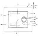
- FIG. 1 is a plan view of an angular velocity sensor according to a first embodiment of the present disclosure.
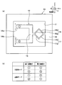
- A) of FIG. 2 is a figure which shows the action
- (b) of FIG. 2 is a figure which shows the pattern of the action
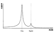
- FIG. 3 is a diagram showing a frequency characteristic (response curve) of a resonance magnification of a general angular velocity sensor, FIG.
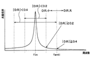
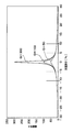
- FIG. 4 is a diagram illustrating a frequency characteristic (response curve) of the resonance magnification of the angular velocity sensor of the first embodiment.
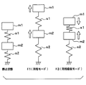
- FIG. 5 is a schematic diagram showing the movement of the common mode and the common mode absorption mode with respect to a stationary state
- FIG. 7 is a graph of Formula 1 when the Q value is changed.
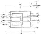
- FIG. 8 is a plan view of an angular velocity sensor according to the second embodiment of the present disclosure.
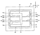
- FIG. 9 is a plan view of an angular velocity sensor according to the third embodiment of the present disclosure.
- angular velocity sensor of the present embodiment is preferably applied to a device that detects an angular velocity applied to the vehicle.
- the angular velocity sensor includes a substrate 10 made of quartz or PZT (zircon lead titanate) as a piezoelectric material.
- the substrate 10 is subjected to well-known micromachining to form a groove portion 11, and the vibrating body 12 and the outer peripheral portion 13 are partitioned by the groove portion 11.
- the outer peripheral portion 13 is partitioned from the vibrating body 12 so as to be positioned around the vibrating body 12.
- the first vibrating piece 14a and the second vibrating piece 14b are held by the base 15.
- the base 15 has a planar rectangular shape having a longitudinal direction (up and down direction in FIG. 1).
- the first vibrating piece 14a and the second vibrating piece 14b are arranged so as to protrude in the same direction at both ends of the base portion 15 in the longitudinal direction. That is, the vibrating body 12 of the present embodiment is a so-called tuning fork type.
- a drive electrode and a detection electrode are formed on each of the vibration pieces 14a and 14b.
- a drive electrode is formed on the base 15 side of each vibrating piece 14a and 14b
- a detection electrode is formed on the side opposite to the base 15 side of each vibrating piece 14a and 14b.
- the vibrating body 12 is supported by the outer peripheral portion 13 via the first beam portion 16 and the second beam portion 17.
- the projecting direction of the first vibrating piece 14a and the second vibrating piece 14b with respect to the base 15 is the x-axis direction
- the direction orthogonal to the projecting direction in the plane of the substrate 10 is the first vibration piece 14a and the second vibration piece 14b
- the first vibration piece 14a and the second vibration piece 14b are arranged in the y-axis direction
- the normal direction to the surface direction of the substrate 10 is the z-axis direction.
- the y-axis direction corresponds to the first direction
- the x-axis direction corresponds to the second direction
- the z-axis direction corresponds to the third direction.
- the first beam portion 16 includes a first beam component member 16a and a second beam component member 16b that are inclined with respect to the x-axis direction and the y-axis direction.
- the first beam portion 16 is composed of a first beam constituent member 16a and a second beam constituent member 16b that are displaceable in the x-axis direction and the y-axis direction.
- the first beam constituent member 16a is disposed on the vibrating body 12 side
- the second beam constituent member 16b is disposed on the outer peripheral portion 13 side.
- the first beam constituent member 16a and the second beam It is made into the substantially V shape with which the structural member 16b was connected.
- the 2nd beam part 17 is comprised by the 1st beam structural member 17a and the 2nd beam structural member 17b which inclined with respect to the x-axis direction and the y-axis direction.
- the second beam portion 17 includes a first beam component member 17a and a second beam component member 17b that can be displaced in the x-axis direction and the y-axis direction.
- the first beam constituent member 17a is arranged on the vibrating body 12 side and the second beam constituent member 17b is arranged on the outer peripheral portion 13 side, and the first beam constituent member 17a and the second beam It is made into the substantially V shape with which the structural member 17b was connected.
- the 2nd beam part 17 is made into the substantially V shape which has a convex part on the opposite side to the substantially V shape which the 1st beam part 16 comprises.
- the 1st beam part 16 and the 2nd beam part 17 are connected with the vibrating body 12 in the state which the edge part by the side of the vibrating body 12 in each 1st beam structural member 16a, 17a was connected and integrated. Moreover, the 1st beam part 16 and the 2nd beam part 17 are connected with the outer peripheral part 13 in the state which the edge part by the side of the outer peripheral part 13 in each 2nd beam structural member 16b, 17b was connected and integrated. . That is, in the present embodiment, the first beam portion 16 and the second beam portion 17 form a planar frame-shaped beam portion, and one set of two sets of corner portions of the frame-shaped beam portion facing each other. It can be said that the corner is connected to the vibrating body 12 and the outer peripheral portion 13.
- the first beam portion 16 and the second beam portion 17 have a cross-sectional area, a length, and the like as appropriate so that the spring constant is smaller than the spring constant of the first vibrating piece 14a and the second vibrating piece 14b. Has been adjusted.
- a drive signal is applied to the drive electrodes formed on the first vibrating piece 14a and the second vibrating piece 14b.
- the driving signals applied to the first vibrating piece 14a and the second vibrating piece 14b are pulsed driving signals having a predetermined amplitude and frequency, and have phases different from each other by 180 °.
- the first vibrating piece 14 a and the second vibrating piece 14 b drive and vibrate in opposite directions along the y-axis direction. In other words, the first vibrating piece 14a and the second vibrating piece 14b vibrate so as to open and close each other.
- the first vibrating piece 14a and the second vibrating piece 14b vibrate in the opposite direction in the z-axis direction due to the Coriolis force.
- the first vibrating piece 14a vibrates in the direction perpendicular to the middle sheet surface of FIG. 2A
- the second vibrating piece 14b vibrates to the front side in the perpendicular direction of the middle sheet surface of FIG.
- a charge corresponding to the vibration is generated on detection electrodes (not shown) formed on the first vibrating piece 14a and the second vibrating piece 14b.
- the angular velocity is detected by differentially amplifying the charge generated in each detection electrode.
- a symbol with a black circle in the circle indicates the other side in the vertical direction of the paper surface
- a symbol with a cross in the circle indicates the vertical direction of the paper surface. It shows that it vibrates to the near side.
- the vibrating body 12 is supported by the outer peripheral portion 13 via the first beam portion 16 and the second beam portion 17. For this reason, when the first beam portion 16 and the second beam portion 17 are displaced (bends) in the x-axis direction and the y-axis direction, disturbances such as vibration and impact are transmitted from the outer peripheral portion 13 to the vibrating body 12. This can be suppressed.
- the second beam constituent members 16b and 17b in the first beam portion 16 and the second beam portion 17 are integrated. For this reason, since the 1st beam part 16 and the 2nd beam part 17 mutually couple
- FIG. 1st beam part 16 and the 2nd beam part 17 mutually couple
- the angular velocity is detected based on the detection principle as described above, but the first vibrating piece 14a and the second vibrating piece 14b are mutually in resonance with the resonance frequency fin of the common mode that vibrates in the same direction in the z-axis direction. It has a resonance frequency fanti of a reverse phase mode that vibrates in the reverse direction.
- the common mode here means that the first vibrating piece 14a and the second vibrating piece 14b are moved in the z-axis direction when an impact along the z-axis direction is applied. It means that it can be vibrated in the same direction.
- the reverse phase mode here means that the first vibrating piece 14a and the second vibrating piece 14b are vibrated in the opposite directions in the z-axis direction when an impact along the z-axis direction is applied. ing.
- the detection electrodes formed on the first vibrating piece 14a and the second vibrating piece 14b By differential amplification (differential output) of the electric charges generated in, the electric charges (signals) resulting from the vibration based on the impact are canceled out.
- differential amplification differential output
- the first vibrating piece 14a and the second vibrating piece 14b change in the anti-phase mode
- charges (signals) resulting from the vibration based on the impact are caused by differential amplification. It is not canceled out, and becomes an output error, and the detection accuracy decreases.
- the resonance magnification (response strength) changes according to the frequency component included in the impact.
- the frequency characteristic (response curve) of the resonance magnification is as shown in FIG. 3 at the resonance frequency fin of the common mode.
- the resonance magnification is the largest.
- the resonance magnification rapidly decreases in other frequency regions centering on the resonance frequency fin of the common mode, and decreases as the distance from the resonance frequency fin of the common mode decreases.
- the resonance frequency fanti of the anti-phase mode exists separately from the resonance frequency fin of the common mode, and the resonance frequency fanti of the anti-phase mode is sufficiently smaller than the resonance frequency fin of the common mode, but the resonance magnification is increased to some extent. Then, the resonance frequency fanti component of the antiphase mode included in the impact induces a movement that vibrates the first vibrating piece 14a and the second vibrating piece 14b in the reverse direction, and generates an output error.
- the resonance magnification at the resonance frequency fanti increases as the resonance frequency fanti is closer to the resonance frequency fin of the in-phase mode. That is, as shown in FIG. 3, the resonance magnification is attenuated centering on the resonance frequency fin of the common mode.
- the resonance frequency fanti of the anti-phase mode is too close to the resonance frequency fin of the common mode, the resonance frequency fanti component of the anti-phase mode included in the impact exists in a region where it is not sufficiently attenuated when an impact is applied. become. For this reason, the resonance frequency fanti component of the non-damped anti-phase mode in the shock induces the anti-phase mode motion in this vibration.
- the resonance frequency fanti component of the anti-phase mode included in the impact can be made a sufficiently attenuated region, It can be said that the induction of movement can be suppressed.
- the frequency characteristic of the resonance magnification can be adjusted based on the setting of the first vibrating piece 14a and the second vibrating piece 14b in the case of the spring that allows displacement in the z-axis direction, that is, in the case of this embodiment. As shown in FIG. 4, when the resonance frequency fanti in the anti-phase mode is separated from the resonance frequency fin in the in-phase mode, the resonance magnification at the resonance frequency fanti in the anti-phase mode can be reduced.
- a value obtained by dividing the difference between the resonance frequency fanti of the antiphase mode and the resonance frequency fin of the common mode by the resonance frequency fanti of the antiphase mode is a decoupling ratio (Decoupling Ratio).
- the absolute value of DR is 0.2 or more
- the resonance magnification is 1 regardless of whether the peak value (Q value: resonance magnification at the resonance frequency fin) is large or small. It can be set to a region where robustness can be ensured with an error of about 30%, and preferably when the absolute value of DR is 0.4 or more, the resonance magnification at the resonance frequency fanti in the antiphase mode is set to 1 or less.
- the resonance frequency fanti component of the anti-phase mode included in the impact is more sufficiently attenuated, and the induction of the anti-phase mode motion can be suppressed.
- Hz if the resonance frequency fanti reverse phase mode and 16 kHz, D. R. absolute value of. Becomes 0.4 or more, so that the resonance magnification becomes 1 or less.
- the absolute value of D.R. is 0.2 or more, preferably 0.4 or more.
- such an angular velocity sensor has two resonance mode frequencies f1 and f3 with respect to application of an impact in a direction along the y-axis direction.
- the two weights m1, m2 is the resonance frequency f3 of the in-phase absorption mode in which vibration is performed in the opposite direction.
- the spring s2 is constituted by the first beam portion 16 and the second beam portion 17
- the weight m2 is constituted by the base portion 15
- the spring s1 is constituted by the first vibrating piece 14a and the second vibrating piece 14b.
- the weight m1 is composed of the first vibrating piece 14a and the second vibrating piece 14b.
- the resonance frequency f3 of the common-mode absorption mode is higher than the resonance frequency f1 of the common-mode mode.
- the first vibrating piece 14a, the second vibrating piece 14b, and the base 15 are (1) vibration excited by non-resonance, (2) vibration excitation by resonance, (3) It is vibrated by a displacement mechanism by adding three vibration excitations by resonance interference. That is, the first vibrating piece 14a, the second vibrating piece 14b, and the base portion 15 are displaced (vibrated) by generating the vibration excitations (1) to (3) so as to be added together.
- Vibration excitation due to non-resonance is simply a displacement amount calculated from inertial force and spring force. Further, (2) vibration excitation by resonance is performed by applying an impact component having the same frequency as the resonance frequency f1 of the angular velocity sensor, mainly the in-phase resonance frequency f1, and the Q value specific to the vibrating body 12 (peak value of resonance magnification). The amount of excitation calculated from Then, (3) vibration excitation by resonance interference is an excitation amount by interference at an integral multiple (n times) of the resonance frequency f1 of the common mode and the resonance frequency f3 of the common mode absorption mode.
- f1 represents the resonance frequency f1 of the common mode
- f3 represents the resonance frequency f3 of the common mode absorption mode
- n represents an integer
- Q represents the Q value.
- FIG. 7 is a graph of Equation 1 with the Q value changed.
- the avoidance difference D in FIG. 7 indicates the degree to which the absolute value ⁇ f3 of the difference between the resonance frequency f3 of the common mode absorption mode and the value n times the resonance frequency f1 of the common mode is deviated from the resonance frequency f1 of the common mode. Yes.
- the avoidance difference D 0, that is, when the absolute value ⁇ f3 coincides with the resonance frequency f1 of the common mode, the amplification factor A becomes the largest.
- (3) vibration excitation due to resonance interference appears as the largest peak value, and the contribution ratio in the total vibration excitation becomes high.
- the avoidance difference D is designed to be larger than 5% (D> 5%)
- the first term in the root of the denominator in Equation 1 is sufficiently larger than the second term
- the second term The amplification factor A can be determined regardless of the Q value included in the. Specifically, as shown in FIG. 7, the amplification factor A decreases to about 20.
- the amplification factor A can be set regardless of the Q value, and the amplification factor A can be made sufficiently small, so that the robustness can be improved.
- Absolute value ⁇ f3 satisfies the following condition. That is, at least the avoidance difference D is greater than 0% while the absolute value ⁇ f3 is greater than the value obtained by multiplying the resonance frequency f1 of the common mode by the avoidance difference D ( ⁇ f3> f1 ⁇ D).
- the amplification factor A can be reduced regardless of the Q value, and the robustness can be improved. More preferably, when the avoidance difference D> 10%, the amplification factor A can be reduced to almost one digit, and (3) vibration excitation due to resonance interference is (1) vibration excitation due to non-resonance or (2) It can be suppressed to a state sufficiently reduced to the same level as vibration excitation by resonance.
- Vibration excitation due to resonance interference can be reduced by designing the resonance frequency f1 of the common mode satisfying such a relationship and the resonance frequency f3 of the common mode absorption mode.
- the amplification factor A is defined by an integral multiple (n times) of the resonance frequency f1 of the common mode, the resonance frequency f3 of the common mode absorption mode, and the Q value.
- the amplification factor A can also be reduced by reducing the Q value.
- the Q value can be lowered by lowering the degree of vacuum at that time.
- the amplification factor A can be reduced, and (3) vibration excitation due to resonance interference can be reduced.
- the Q value is reduced, (2) vibration excitation due to resonance is also reduced, and (3) it is reduced together with vibration excitation due to resonance interference, and it is possible to further improve impact resistance performance. Become.
- the vibrating body 12 is supported by the outer peripheral portion 13 via the first beam portion 16 and the second beam portion 17. For this reason, when the first beam portion 16 and the second beam portion 17 are displaced (bends) in the x-axis direction and the y-axis direction, disturbances such as vibration and impact are transmitted from the outer peripheral portion 13 to the vibrating body 12. This can be suppressed.
- the second beam constituent members 16b and 17b in the first beam portion 16 and the second beam portion 17 are integrated. For this reason, since the first beam portion 16 and the second beam portion 17 are coupled to each other, the transmission of disturbance from the outer peripheral portion 13 to the vibrating body 12 can be further suppressed, and the detection accuracy is further reduced. This can be suppressed.
- the spring constants of the first beam portion 16 and the second beam portion 17 are smaller than the spring constants of the first vibrating piece 14a and the second vibrating piece 14b. For this reason, compared with the case where the spring constant of the 1st beam part 16 and the 2nd beam part 17 is made larger than the spring constant which the 1st vibration piece 14a and the 2nd vibration piece 14b have, it is a vibrating body from the outer peripheral part 13. Transmission of disturbance to 12 can be suppressed.
- the absolute value of D.R. is 0.2 or more. For this reason, even if an impact in the z-axis direction is applied to the angular velocity sensor, it is possible to suppress the induction of the motion in the reverse phase mode. For this reason, generation
- the absolute value ⁇ f3 is greater than the value obtained by multiplying the resonance frequency f1 in the common mode by the avoidance difference D ( ⁇ f3> f1 ⁇ D), and at least the avoidance difference D is greater than 0%. growing. For this reason, it can suppress that the vibration excitation by resonance interference becomes the maximum displacement, and can improve impact resistance performance.
- the vibrating body 12 is opposite to the first beam portion 16 and the second beam portion 17 with the vibrating body 12 sandwiched between the first beam portion 16 and the second beam portion 17. It is supported by the outer peripheral part 13 through the 3rd, 4th beam parts 18 and 19 arrange
- the first beam portion 16 and the second beam portions 16, 17 are connected to the first beam constituent members 16a, 17a extending in the x-axis direction and the first beam constituent members 16a, 17a, and the second beam extending in the y-axis direction. It has structural members 16b and 17b. That is, the first beam portion 16 and the second beam portion 17 include first beam constituent members 16a and 17a that are displaceable in the y-axis direction, and second beam constituent members 16b that are displaceable in the x-axis direction. 17b. And the 2nd beam structural member 16b of the 1st beam part 16 and the 2nd beam structural member 17b of the 2nd beam part 17 are integrated.
- the third and fourth beam portions 18, 19 are connected to the first beam constituent members 18a, 19a extending in the x-axis direction and the first beam constituent members 18a, 19a, and the second beam extending in the y-axis direction. It has structural members 18b and 19b. That is, the third and fourth beam portions 18 and 19 are first beam constituent members 18a and 19a that are displaceable in the y-axis direction, and second beam constituent members 18b and 19b that are displaceable in the x-axis direction. And have. And the 2nd beam structural member 18b of the 3rd beam part 18 and the 2nd beam structural member 19b of the 4th beam part 19 are integrated.
- first to fourth beam portions 16 to 19 may be provided, and the first and second beam constituting members 16a to 19b may be displaced only in one direction. Also in such an angular velocity sensor, the second beam constituent members 16b and 17b of the first beam portion 16 and the second beam portion 17 are integrated, and the second beam constituent members 18b of the third and fourth beam portions 18 and 19 are integrated. , 19b are integrated, the same effect as in the first embodiment can be obtained.
- a frame portion 20 surrounding the vibration body 12 is formed between the vibration body 12 and the outer peripheral portion 13, and the frame portion 20 includes a plurality of support portions 21. It is supported by the outer peripheral part 13 via.
- the first beam constituting members 16a to 19a are respectively connected to the frame portion 20, and the second beam constituting members 16b to 19b are constituted by the frame portion 20. That is, the second beam constituent members 16b to 19b in the first to fourth beam portions 16 to 19 are all integrated.
- the first to fourth beam portions 16 to 19 further suppress the transmission of disturbance from the outer peripheral portion 13 to the vibrating body 12 because all the displacements of the beam portions 16 to 19 are coupled to each other.
- the same effect as the second embodiment can be obtained.
- the frame portion 20 (the second beam constituent members 16b to 19b in the first to fourth beam portions 16 to 19) is supported by the outer peripheral portion 13 via the plurality of support portions 21 has been described.
- the frame portion 20 may be supported by the outer peripheral portion 13 through only one support portion 21.
- the configuration of the vibrating body 12 may be changed.
- the vibrating body 12 may be a so-called H-type tuning fork in which the first vibrating piece 14 a and the second vibrating piece 14 b protrude in both directions with respect to the base portion 15.
- the vibrating body 12 is a so-called tripod tuning fork having a detection piece protruding in the same direction as the first vibrating piece 14a and the second vibrating piece 14b between the first vibrating piece 14a and the second vibrating piece 14b. Also good.
- the first vibrating piece 14a and the second vibrating piece 14b serve as driving pieces, and the angular velocity is detected based on the electric charge generated in the detecting piece.
- the angular velocity is detected based on the charge generated in the detection piece. That is, the angular velocity is detected without performing differential amplification.
- the vibrating body 12 may be a so-called double T-type tuning fork in which the first vibrating piece 14a, the second vibrating piece 14b, and the detection piece protrude from the base 15 on both sides.
- the end portions on the base 15 side in the first beam constituting members 16a and 17a may not be integrated, and may be provided in the base 15 respectively.
- the spring constants of the beam portions 16 to 19 may be larger than the spring constants of the first vibrating piece 14a and the second vibrating piece 14b.
Abstract
In the present invention, when one direction of the plane directions of a substrate (10) is a first direction and the direction perpendicular to the first direction of the plane directions of the substrate (10) is a second direction, an oscillating body (12) is supported at an outer peripheral section (13) via a plurality of beam sections (16-19) therebetween having a first beam-configuring member (16a-19a) that can displace in at least the first direction, and a second beam-configuring member (16b-19b) that is joined to the first beam-configuring member (16a-19a) and that can displace in at least the second direction. Also, at least at a subset of the plurality of the beam sections (16-19), the beam configuring members (16b-19b) at the outer peripheral section (13) side among the first beam-configuring members and second beam-configuring members (16a-19b) are integrated with each other.
Description
本出願は、2014年6月13日に出願された日本出願番号2014-122512号に基づくもので、ここにその記載内容を援用する。
This application is based on Japanese Application No. 2014-122512 filed on June 13, 2014, the contents of which are incorporated herein by reference.
本開示は、振動体を有する角速度センサに関するものである。
This disclosure relates to an angular velocity sensor having a vibrating body.
従来より、振動片が基部に固定された振動体を有する角速度センサが提案記載されている(例えば、特許文献1参照)。具体的には、この角速度センサは、圧電材料で構成される基板を用いて構成されており、基板に振動体と振動体を囲む外周部とが区画形成されている。そして、振動体は、外周部に複数の梁部を介して支持されている。
Conventionally, an angular velocity sensor having a vibrating body having a vibrating piece fixed to the base has been proposed (for example, see Patent Document 1). Specifically, this angular velocity sensor is configured using a substrate made of a piezoelectric material, and a vibrating body and an outer peripheral portion surrounding the vibrating body are partitioned on the substrate. The vibrating body is supported on the outer periphery via a plurality of beam portions.
これによれば、振動体(基部)と外周部との間に配置された梁部により、外周部から振動体に振動や衝撃等の外乱が伝達されることを抑制でき、検出精度が低下することを抑制できる。
According to this, by the beam part arranged between the vibrating body (base) and the outer peripheral part, it is possible to suppress the transmission of disturbances such as vibration and impact from the outer peripheral part to the vibrating body, and the detection accuracy is lowered. This can be suppressed.
しかしながら、上記角速度センサでは、各梁部は、それぞれ独立して外周部と接続されている。このため、各梁部によって外乱の抑制効果が異なり、検出精度が低下することを十分に抑制できない場合がある。
However, in the angular velocity sensor, each beam portion is independently connected to the outer peripheral portion. For this reason, the effect of suppressing disturbance differs depending on each beam part, and it may not be possible to sufficiently suppress a decrease in detection accuracy.
本開示は上記点に鑑みて、検出精度が低下することを抑制できる角速度センサを提供することを目的とする。
This indication aims at providing the angular velocity sensor which can control that detection accuracy falls in view of the above-mentioned point.
本開示の第一の態様において、角速度センサは、圧電材料を用いて構成される基板と、基板に形成され、基板の面方向に振動する第1振動片と第2振動片を有する振動体と、基板に形成され、振動体の周囲に配置される外周部と、を備え、振動体を振動させた状態で角速度が印加されると当該角速度に応じた電荷を発生する。
In the first aspect of the present disclosure, the angular velocity sensor includes a substrate configured using a piezoelectric material, a vibrating body formed on the substrate, and having a first vibrating piece and a second vibrating piece that vibrate in a surface direction of the substrate. And an outer peripheral portion formed on the substrate and arranged around the vibrating body, and when an angular velocity is applied in a state where the vibrating body is vibrated, an electric charge corresponding to the angular velocity is generated.
振動体は、基板の面方向における一方向を第1方向とし、基板の面方向のうちの第1方向と直交する方向を第2方向としたとき、少なくとも第1方向に変位可能とされた第1梁構成部材と、第1梁構成部材と連結され、少なくとも第2方向に変位可能とされた第2梁構成部材とを有する複数の梁部を介して外周部に支持され、複数の梁部の少なくとも一部は、第1梁構成部材と第2梁構成部材のうちの外周部側の梁構成部材が互いに一体化されている。
The vibrating body is displaceable at least in the first direction when one direction in the surface direction of the substrate is a first direction and a direction orthogonal to the first direction of the surface directions of the substrate is a second direction. A plurality of beam portions supported on the outer periphery via a plurality of beam portions having one beam component member and a second beam component member coupled to the first beam component member and displaceable in at least the second direction. At least a part of the beam component members on the outer peripheral portion side of the first beam component member and the second beam component member are integrated with each other.
これによれば、梁部のうちの外周部側の梁構成部材が一体化されている部分では、変位を互いに連成し合うため、外周部から振動体に外乱が伝達されることをさらに抑制でき、検出精度が低下することを抑制できる。
According to this, in the part where the beam constituent members on the outer peripheral part side of the beam part are integrated, the displacement is coupled to each other, so that the disturbance is further prevented from being transmitted from the outer peripheral part to the vibrating body. It can suppress and it can suppress that detection accuracy falls.
本開示についての上記目的およびその他の目的、特徴や利点は、添付の図面を参照しながら下記の詳細な記述により、より明確になる。その図面は、
図1は、本開示の第1実施形態における角速度センサの平面図であり、
図2の(a)は、図1に示す角速度センサの作動を示す図であり、図2の(b)は、図2の(a)に示す角速度センサの作動のパターンを示す図であり、
図3は、一般的な角速度センサの共振倍率の周波数特性(応答曲線)を示した図であり、
図4は、第1実施形態の角速度センサの共振倍率の周波数特性(応答曲線)を示した図であり、
図5は、静止状態に対する同相モードと同相吸収モードの動きを示した模式図であり、
図6Aは、図1に示す角速度センサに対してy軸方向に衝撃が印加されたときの同相モードの動きを示した模式図であり、
図6Bは、図1に示す角速度センサに対してy軸方向に衝撃が印加されたときの同相吸収モードの動きを示した模式図であり、
図7は、Q値を変化させときの数式1のグラフであり、
図8は、本開示の第2実施形態における角速度センサの平面図であり、
図9は、本開示の第3実施形態における角速度センサの平面図である。
The above and other objects, features and advantages of the present disclosure will become more apparent from the following detailed description with reference to the accompanying drawings. The drawing
FIG. 1 is a plan view of an angular velocity sensor according to a first embodiment of the present disclosure. (A) of FIG. 2 is a figure which shows the action | operation of the angular velocity sensor shown in FIG. 1, (b) of FIG. 2 is a figure which shows the pattern of the action | operation of the angular velocity sensor shown in (a) of FIG. FIG. 3 is a diagram showing a frequency characteristic (response curve) of a resonance magnification of a general angular velocity sensor, FIG. 4 is a diagram illustrating a frequency characteristic (response curve) of the resonance magnification of the angular velocity sensor of the first embodiment. FIG. 5 is a schematic diagram showing the movement of the common mode and the common mode absorption mode with respect to a stationary state, FIG. 6A is a schematic diagram showing the movement in the common mode when an impact is applied in the y-axis direction to the angular velocity sensor shown in FIG. 6B is a schematic diagram illustrating the movement of the common mode absorption mode when an impact is applied to the angular velocity sensor illustrated in FIG. 1 in the y-axis direction. FIG. 7 is a graph of Formula 1 when the Q value is changed. FIG. 8 is a plan view of an angular velocity sensor according to the second embodiment of the present disclosure. FIG. 9 is a plan view of an angular velocity sensor according to the third embodiment of the present disclosure.
以下、本開示の実施形態について図に基づいて説明する。なお、以下の各実施形態相互において、互いに同一もしくは均等である部分には、同一符号を付して説明を行う。
Hereinafter, embodiments of the present disclosure will be described with reference to the drawings. In the following embodiments, parts that are the same or equivalent to each other will be described with the same reference numerals.
(第1実施形態)
本開示の第1実施形態について図面を参照しつつ説明する。なお、本実施形態の角速度センサは、車両に印加される角速度を検出するものに適用されると好適である。 (First embodiment)
A first embodiment of the present disclosure will be described with reference to the drawings. It should be noted that the angular velocity sensor of the present embodiment is preferably applied to a device that detects an angular velocity applied to the vehicle.
角速度センサは、図1に示されるように、圧電材料としての水晶やPZT(チタン酸ジルコン鉛)等で構成される基板10を備えている。そして、基板10には、周知のマイクロマシン加工が施されて溝部11が形成され、溝部11によって振動体12および外周部13が区画形成されている。なお、外周部13は、振動体12の周囲に位置するように、振動体12と区画形成されている。
As shown in FIG. 1, the angular velocity sensor includes a substrate 10 made of quartz or PZT (zircon lead titanate) as a piezoelectric material. The substrate 10 is subjected to well-known micromachining to form a groove portion 11, and the vibrating body 12 and the outer peripheral portion 13 are partitioned by the groove portion 11. The outer peripheral portion 13 is partitioned from the vibrating body 12 so as to be positioned around the vibrating body 12.
振動体12は、第1振動片14aと第2振動片14bが基部15に保持された。具体的には、基部15は、長手方向(図1中紙面上下方向)を有する平面矩形状とされている。そして、第1振動片14aと第2振動片14bは、基部15における長手方向の両端部において同じ方向に突出するように配置されている。つまり、本実施形態の振動体12は、いわゆる音叉型とされている。
In the vibrating body 12, the first vibrating piece 14a and the second vibrating piece 14b are held by the base 15. Specifically, the base 15 has a planar rectangular shape having a longitudinal direction (up and down direction in FIG. 1). The first vibrating piece 14a and the second vibrating piece 14b are arranged so as to protrude in the same direction at both ends of the base portion 15 in the longitudinal direction. That is, the vibrating body 12 of the present embodiment is a so-called tuning fork type.
また、各振動片14aと14bには、図示しない駆動電極および検出電極が形成されている。例えば、各振動片14aと14bのうちの基部15側に駆動電極が形成され、各振動片14aと14bのうちの基部15側と反対側に検出電極が形成されている。
Further, a drive electrode and a detection electrode (not shown) are formed on each of the vibration pieces 14a and 14b. For example, a drive electrode is formed on the base 15 side of each vibrating piece 14a and 14b, and a detection electrode is formed on the side opposite to the base 15 side of each vibrating piece 14a and 14b.
そして、振動体12は、第1梁部16と第2梁部17を介して外周部13に支持されている。ここで、第1梁部16と第2梁部17の具体的な構成について説明する。なお、以下では、第1振動片14aと第2振動片14bの基部15に対する突出方向(図1中紙面左右方向)をx軸方向とし、基板10の面内において当該突出方向と直交する方向(第1振動片14aと第2振動片14bの配列方向)をy軸方向とし、基板10の面方向に対する法線方向をz軸方向として説明する。また、本実施形態では、y軸方向が第1方向に相当し、x軸方向が第2方向に相当し、z軸方向が第3方向に相当している。
The vibrating body 12 is supported by the outer peripheral portion 13 via the first beam portion 16 and the second beam portion 17. Here, specific configurations of the first beam portion 16 and the second beam portion 17 will be described. In the following description, the projecting direction of the first vibrating piece 14a and the second vibrating piece 14b with respect to the base 15 (the left-right direction in FIG. 1) is the x-axis direction, and the direction orthogonal to the projecting direction in the plane of the substrate 10 ( In the following description, the first vibration piece 14a and the second vibration piece 14b are arranged in the y-axis direction, and the normal direction to the surface direction of the substrate 10 is the z-axis direction. In the present embodiment, the y-axis direction corresponds to the first direction, the x-axis direction corresponds to the second direction, and the z-axis direction corresponds to the third direction.
第1梁部16は、x軸方向およびy軸方向に対して傾いた第1梁構成部材16aと第2梁構成部材16bにて構成されている。言い換えると、第1梁部16は、x軸方向およびy軸方向に変位可能とされた第1梁構成部材16aと第2梁構成部材16bにて構成されている。そして、第1梁部16は、第1梁構成部材16aが振動体12側に配置されると共に第2梁構成部材16bが外周部13側に配置され、第1梁構成部材16aと第2梁構成部材16bが連結された略V字状とされている。
The first beam portion 16 includes a first beam component member 16a and a second beam component member 16b that are inclined with respect to the x-axis direction and the y-axis direction. In other words, the first beam portion 16 is composed of a first beam constituent member 16a and a second beam constituent member 16b that are displaceable in the x-axis direction and the y-axis direction. In the first beam portion 16, the first beam constituent member 16a is disposed on the vibrating body 12 side, and the second beam constituent member 16b is disposed on the outer peripheral portion 13 side. The first beam constituent member 16a and the second beam It is made into the substantially V shape with which the structural member 16b was connected.
同様に、第2梁部17は、x軸方向およびy軸方向に対して傾いた第1梁構成部材17aと第2梁構成部材17bにて構成されている。言い換えると、第2梁部17は、x軸方向およびy軸方向に変位可能とされた第1梁構成部材17aと第2梁構成部材17bにて構成されている。そして、第2梁部17は、第1梁構成部材17aが振動体12側に配置されると共に第2梁構成部材17bが外周部13側に配置され、第1梁構成部材17aと第2梁構成部材17bが連結された略V字状とされている。なお、第2梁部17は、第1梁部16が構成する略V字状と反対側に凸部を有する略V字状とされている。
Similarly, the 2nd beam part 17 is comprised by the 1st beam structural member 17a and the 2nd beam structural member 17b which inclined with respect to the x-axis direction and the y-axis direction. In other words, the second beam portion 17 includes a first beam component member 17a and a second beam component member 17b that can be displaced in the x-axis direction and the y-axis direction. In the second beam portion 17, the first beam constituent member 17a is arranged on the vibrating body 12 side and the second beam constituent member 17b is arranged on the outer peripheral portion 13 side, and the first beam constituent member 17a and the second beam It is made into the substantially V shape with which the structural member 17b was connected. In addition, the 2nd beam part 17 is made into the substantially V shape which has a convex part on the opposite side to the substantially V shape which the 1st beam part 16 comprises.
そして、第1梁部16および第2梁部17は、各第1梁構成部材16a、17aにおける振動体12側の端部が連結されて一体化された状態で振動体12と連結されている。また、第1梁部16および第2梁部17は、各第2梁構成部材16b、17bにおける外周部13側の端部が連結されて一体化された状態で外周部13と連結されている。つまり、本実施形態では、第1梁部16と第2梁部17により、平面枠状の梁部が構成され、当該枠状の梁部の相対する2組の角部のうちの1組の角部が振動体12および外周部13と連結されているともいえる。
And the 1st beam part 16 and the 2nd beam part 17 are connected with the vibrating body 12 in the state which the edge part by the side of the vibrating body 12 in each 1st beam structural member 16a, 17a was connected and integrated. . Moreover, the 1st beam part 16 and the 2nd beam part 17 are connected with the outer peripheral part 13 in the state which the edge part by the side of the outer peripheral part 13 in each 2nd beam structural member 16b, 17b was connected and integrated. . That is, in the present embodiment, the first beam portion 16 and the second beam portion 17 form a planar frame-shaped beam portion, and one set of two sets of corner portions of the frame-shaped beam portion facing each other. It can be said that the corner is connected to the vibrating body 12 and the outer peripheral portion 13.
さらに本実施形態では、第1梁部16と第2梁部17は、バネ定数が第1振動片14aと第2振動片14bの有するバネ定数より小さくなるように、適宜断面積や長さ等が調整されている。
Furthermore, in the present embodiment, the first beam portion 16 and the second beam portion 17 have a cross-sectional area, a length, and the like as appropriate so that the spring constant is smaller than the spring constant of the first vibrating piece 14a and the second vibrating piece 14b. Has been adjusted.
このような角速度センサでは、角速度を検出する際には、第1振動片14aと第2振動片14bに形成された駆動電極に駆動信号が印加される。なお、第1振動片14aと第2振動片14bに印加される駆動信号は、所定の振幅、周波数を有するパルス状の駆動信号であり、互いに位相が180°異なるものである。これにより、図2に示されるように、第1振動片14aと第2振動片14bは、y軸方向に沿って逆向きに駆動振動する。言い換えると、第1振動片14aと第2振動片14bは、互いに開閉するように駆動振動する。
In such an angular velocity sensor, when the angular velocity is detected, a drive signal is applied to the drive electrodes formed on the first vibrating piece 14a and the second vibrating piece 14b. The driving signals applied to the first vibrating piece 14a and the second vibrating piece 14b are pulsed driving signals having a predetermined amplitude and frequency, and have phases different from each other by 180 °. Thereby, as shown in FIG. 2, the first vibrating piece 14 a and the second vibrating piece 14 b drive and vibrate in opposite directions along the y-axis direction. In other words, the first vibrating piece 14a and the second vibrating piece 14b vibrate so as to open and close each other.
そして、この状態において、x軸方向周りの角速度が印加されると、コリオリ力によって第1振動片14aと第2振動片14bは、z軸方向に逆向きに振動する。例えば、第1振動片14aが図2の(a)中紙面垂直方向向こう側に振動する場合は、第2振動片14bが図2の(a)中紙面垂直方向手前側に振動する。そして、第1振動片14aと第2振動片14bに形成された図示しない検出電極に振動に応じた電荷が発生する。このため、各検出電極に発生した電荷を差動増幅することにより、角速度の検出が行われる。なお、図2の(a)、図2の(b)中において、丸の中に黒丸を示した記号は紙面垂直方向向こう側を示し、丸の中に×印を示した記号は紙面垂直方向手前側に振動することを示している。
In this state, when an angular velocity around the x-axis direction is applied, the first vibrating piece 14a and the second vibrating piece 14b vibrate in the opposite direction in the z-axis direction due to the Coriolis force. For example, when the first vibrating piece 14a vibrates in the direction perpendicular to the middle sheet surface of FIG. 2A, the second vibrating piece 14b vibrates to the front side in the perpendicular direction of the middle sheet surface of FIG. Then, a charge corresponding to the vibration is generated on detection electrodes (not shown) formed on the first vibrating piece 14a and the second vibrating piece 14b. For this reason, the angular velocity is detected by differentially amplifying the charge generated in each detection electrode. In FIGS. 2A and 2B, a symbol with a black circle in the circle indicates the other side in the vertical direction of the paper surface, and a symbol with a cross in the circle indicates the vertical direction of the paper surface. It shows that it vibrates to the near side.
このとき、振動体12は、第1梁部16と第2梁部17を介して外周部13に支持されている。このため、第1梁部16と第2梁部17がx軸方向およびy軸方向に変位する(撓む)ことにより、外周部13から振動体12に振動や衝撃等の外乱が伝達されることを抑制できる。
At this time, the vibrating body 12 is supported by the outer peripheral portion 13 via the first beam portion 16 and the second beam portion 17. For this reason, when the first beam portion 16 and the second beam portion 17 are displaced (bends) in the x-axis direction and the y-axis direction, disturbances such as vibration and impact are transmitted from the outer peripheral portion 13 to the vibrating body 12. This can be suppressed.
また、第1梁部16と第2梁部17における各第2梁構成部材16b、17bは一体化されている。このため、第1梁部16と第2梁部17は、変位を互いに連成し合うため、さらに外周部13から振動体12に外乱が伝達されることを抑制できる。
Also, the second beam constituent members 16b and 17b in the first beam portion 16 and the second beam portion 17 are integrated. For this reason, since the 1st beam part 16 and the 2nd beam part 17 mutually couple | bond displacement, it can suppress that a disturbance is further transmitted to the vibrating body 12 from the outer peripheral part 13. FIG.
ここで、上記のような検出原理によって角速度の検出を行っているが、第1振動片14aと第2振動片14bは、z軸方向において同方向に振動する同相モードの共振周波数finと、互いに逆方向に振動する逆相モードの共振周波数fantiを有している。
Here, the angular velocity is detected based on the detection principle as described above, but the first vibrating piece 14a and the second vibrating piece 14b are mutually in resonance with the resonance frequency fin of the common mode that vibrates in the same direction in the z-axis direction. It has a resonance frequency fanti of a reverse phase mode that vibrates in the reverse direction.
なお、図2の(b)に示されるように、ここでの同相モードとは、z軸方向に沿った衝撃が印加されたときに第1振動片14aと第2振動片14bがz軸方向において同方向に振動させられることを意味している。また、ここでの逆相モードとは、z軸方向に沿った衝撃が印加されたときに第1振動片14aと第2振動片14bがz軸方向において逆方向に振動させられることを意味している。
As shown in FIG. 2 (b), the common mode here means that the first vibrating piece 14a and the second vibrating piece 14b are moved in the z-axis direction when an impact along the z-axis direction is applied. It means that it can be vibrated in the same direction. Further, the reverse phase mode here means that the first vibrating piece 14a and the second vibrating piece 14b are vibrated in the opposite directions in the z-axis direction when an impact along the z-axis direction is applied. ing.
z軸方向への衝撃が印加されたとき、第1振動片14aと第2振動片14bが同相モードで変化するのであれば、第1振動片14aと第2振動片14bに形成された検出電極に発生した電荷を差動増幅(差動出力)することにより、その衝撃に基づく振動に起因する電荷(信号)が相殺される。しかしながら、z軸方向への衝撃が印加されたとき、第1振動片14aと第2振動片14bが逆相モードで変化すると、差動増幅によってその衝撃に基づく振動に起因する電荷(信号)が相殺されず、出力誤差となって検出精度が低下する。
If the first vibrating piece 14a and the second vibrating piece 14b change in the in-phase mode when an impact in the z-axis direction is applied, the detection electrodes formed on the first vibrating piece 14a and the second vibrating piece 14b By differential amplification (differential output) of the electric charges generated in, the electric charges (signals) resulting from the vibration based on the impact are canceled out. However, when an impact in the z-axis direction is applied, if the first vibrating piece 14a and the second vibrating piece 14b change in the anti-phase mode, charges (signals) resulting from the vibration based on the impact are caused by differential amplification. It is not canceled out, and becomes an output error, and the detection accuracy decreases.
z軸方向への衝撃が印加されたときは、その衝撃に含まれる周波数成分に応じて共振倍率(応答の強さ)が変わる。具体的には、一般的な角速度センサ(共振周波数を特に考慮していない角速度センサ)では、共振倍率の周波数特性(応答曲線)は、図3に示されるように、同相モードの共振周波数finにおいて最も共振倍率が大きくなる。そして、同相モードの共振周波数finを中心として他の周波数域では急激に共振倍率が低下し、同相モードの共振周波数finから離れるほど低下してく。ただし、同相モードの共振周波数finとは別に逆相モードの共振周波数fantiが存在し、この逆相モードの共振周波数fantiでも同相モードの共振周波数finよりは十分小さいものの、共振倍率がある程度大きくなる。そして、衝撃に含まれるこの逆相モードの共振周波数fanti成分が第1振動片14aと第2振動片14bを逆方向へ振動させる動きを誘発し、出力誤差を発生させる。
When an impact in the z-axis direction is applied, the resonance magnification (response strength) changes according to the frequency component included in the impact. Specifically, in a general angular velocity sensor (an angular velocity sensor that does not specifically consider the resonance frequency), the frequency characteristic (response curve) of the resonance magnification is as shown in FIG. 3 at the resonance frequency fin of the common mode. The resonance magnification is the largest. The resonance magnification rapidly decreases in other frequency regions centering on the resonance frequency fin of the common mode, and decreases as the distance from the resonance frequency fin of the common mode decreases. However, the resonance frequency fanti of the anti-phase mode exists separately from the resonance frequency fin of the common mode, and the resonance frequency fanti of the anti-phase mode is sufficiently smaller than the resonance frequency fin of the common mode, but the resonance magnification is increased to some extent. Then, the resonance frequency fanti component of the antiphase mode included in the impact induces a movement that vibrates the first vibrating piece 14a and the second vibrating piece 14b in the reverse direction, and generates an output error.
この逆相モードの共振周波数fantiについては、同相モードの共振周波数finの近くに存在するほどその共振周波数fantiでの共振倍率が大きくなる。すなわち、図3に示されるように同相モードの共振周波数finを中心として共振倍率が減衰されていく。しかしながら、逆相モードの共振周波数fantiが同相モードの共振周波数finに近すぎると、衝撃が印加されたときにその衝撃に含まれる逆相モードの共振周波数fanti成分が十分減衰されない領域に存在することになる。このため、その衝撃における減衰しきっていない逆相モードの共振周波数fanti成分がこの振動における逆相モードの動きを誘発する。
As for the resonance frequency fanti of the anti-phase mode, the resonance magnification at the resonance frequency fanti increases as the resonance frequency fanti is closer to the resonance frequency fin of the in-phase mode. That is, as shown in FIG. 3, the resonance magnification is attenuated centering on the resonance frequency fin of the common mode. However, if the resonance frequency fanti of the anti-phase mode is too close to the resonance frequency fin of the common mode, the resonance frequency fanti component of the anti-phase mode included in the impact exists in a region where it is not sufficiently attenuated when an impact is applied. become. For this reason, the resonance frequency fanti component of the non-damped anti-phase mode in the shock induces the anti-phase mode motion in this vibration.
したがって、同相モードの共振周波数finと逆相モードの共振周波数fantiとが離れることで、衝撃に含まれる逆相モードの共振周波数fanti成分が十分減衰された領域となるようにでき、逆相モードの動きの誘発を抑制することが可能になると言える。共振倍率の周波数特性ついては、z軸方向の変位を許容するバネ、つまり本実施形態の場合であれば第1振動片14aと第2振動片14bの設定に基づいて調整することができる。そして、図4に示すように逆相モードの共振周波数fantiが同相モードの共振周波数finから離れると、逆相モードの共振周波数fantiでの共振倍率を低下させることができる。
Therefore, when the resonance frequency fin of the in-phase mode and the resonance frequency fanti of the anti-phase mode are separated, the resonance frequency fanti component of the anti-phase mode included in the impact can be made a sufficiently attenuated region, It can be said that the induction of movement can be suppressed. The frequency characteristic of the resonance magnification can be adjusted based on the setting of the first vibrating piece 14a and the second vibrating piece 14b in the case of the spring that allows displacement in the z-axis direction, that is, in the case of this embodiment. As shown in FIG. 4, when the resonance frequency fanti in the anti-phase mode is separated from the resonance frequency fin in the in-phase mode, the resonance magnification at the resonance frequency fanti in the anti-phase mode can be reduced.
具体的には、逆相モードの共振周波数fantiと同相モードの共振周波数finの差分を逆相モードの共振周波数fantiで割った値(=(fanti―fin)/fanti)をデカップリング率(Decoupling Ratio(以下、D.R.という)と定義する。すると、D.R.の絶対値を0.2以上にすると、共振倍率はピーク値(Q値:共振周波数finのときの共振倍率)が大きくても小さくても1割程度の誤差で3以下となり、ロバスト性を確保できる領域とすることができる。好ましくはD.R.の絶対値が0.4以上になると逆相モードの共振周波数fantiでの共振倍率を1以下にすることが可能になり、衝撃に含まれる逆相モードの共振周波数fanti成分がより十分減衰され、逆相モードの動きの誘発を抑制することができる。例えば、同相モードの共振周波数finが10kHz、逆相モードの共振周波数fantiが16kHzとすれば、D.R.の絶対値が0.4以上となり、共振倍率が1以下となるようにできる。
Specifically, a value obtained by dividing the difference between the resonance frequency fanti of the antiphase mode and the resonance frequency fin of the common mode by the resonance frequency fanti of the antiphase mode (= (fanti−fin) / fanti) is a decoupling ratio (Decoupling Ratio). Then, when the absolute value of DR is 0.2 or more, the resonance magnification is 1 regardless of whether the peak value (Q value: resonance magnification at the resonance frequency fin) is large or small. It can be set to a region where robustness can be ensured with an error of about 30%, and preferably when the absolute value of DR is 0.4 or more, the resonance magnification at the resonance frequency fanti in the antiphase mode is set to 1 or less. Thus, the resonance frequency fanti component of the anti-phase mode included in the impact is more sufficiently attenuated, and the induction of the anti-phase mode motion can be suppressed. Hz, if the resonance frequency fanti reverse phase mode and 16 kHz, D. R. absolute value of. Becomes 0.4 or more, so that the resonance magnification becomes 1 or less.
このため、本実施形態では、D.R.の絶対値が0.2以上、好ましくは0.4以上となる。これにより、逆相モードの動きの誘発を抑制することができる。したがって、角速度センサの出力誤差を抑制することができ、さらに検出精度が低下することを抑制できる。
For this reason, in this embodiment, the absolute value of D.R. is 0.2 or more, preferably 0.4 or more. Thereby, induction of the movement of a reverse phase mode can be suppressed. Therefore, it is possible to suppress the output error of the angular velocity sensor and further suppress the detection accuracy from being lowered.
また、このような角速度センサは、y軸方向に沿った方向への衝撃の印加に対して2つの共振モードの周波数f1、f3を有している。具体的には、図5において模式的に示されるように、バネs1、s2に支持された2つの錘m1、m2が同方向へ振動させられる同相モードの共振周波数f1と、2つの錘m1、m2が逆方向へ振動させられる同相吸収モードの共振周波数f3である。
Also, such an angular velocity sensor has two resonance mode frequencies f1 and f3 with respect to application of an impact in a direction along the y-axis direction. Specifically, as schematically shown in FIG. 5, the resonance frequency f1 of the common mode in which the two weights m1, m2 supported by the springs s1, s2 are vibrated in the same direction, and the two weights m1, m2 is the resonance frequency f3 of the in-phase absorption mode in which vibration is performed in the opposite direction.
なお、図5において、バネs2は、第1梁部16と第2梁部17によって構成され、錘m2は基部15によって構成され、バネs1は第1振動片14aと第2振動片14bによって構成され、錘m1は第1振動片14aと第2振動片14bによって構成される。また、同相吸収モードの共振周波数f3は、同相モードの共振周波数f1よりも大きな周波数となる。
In FIG. 5, the spring s2 is constituted by the first beam portion 16 and the second beam portion 17, the weight m2 is constituted by the base portion 15, and the spring s1 is constituted by the first vibrating piece 14a and the second vibrating piece 14b. The weight m1 is composed of the first vibrating piece 14a and the second vibrating piece 14b. Further, the resonance frequency f3 of the common-mode absorption mode is higher than the resonance frequency f1 of the common-mode mode.
すなわち、図6Aに示されるように、角速度センサに対してy軸方向に衝撃が印加されたとき、同相モードの共振周波数f1では、y軸方向において第1振動片14aと第2振動片14bと基部15とが同方向に振動させられる。これに対し、図6Bに示されるように、角速度センサに対してy軸方向に衝撃が印加されたとき、同相吸収モードの共振周波数f3では、y軸方向において第1振動片14aと第2振動片14bと基部15とが逆方向に振動させられる。
That is, as shown in FIG. 6A, when an impact is applied to the angular velocity sensor in the y-axis direction, at the resonance frequency f1 in the in-phase mode, the first vibrating piece 14a and the second vibrating piece 14b in the y-axis direction The base 15 is vibrated in the same direction. On the other hand, as shown in FIG. 6B, when an impact is applied to the angular velocity sensor in the y-axis direction, the first vibrating piece 14a and the second vibration in the y-axis direction at the resonance frequency f3 in the in-phase absorption mode. The piece 14b and the base 15 are vibrated in the opposite directions.
ここで、角速度センサにy軸方向に衝撃が印加されると、第1振動片14aと第2振動片14bおよび基部15は、(1)非共振による振動励起、(2)共振による振動励起、(3)共振干渉による振動励起、の3つの足し合わせによる変位メカニズムにて振動させられる。つまり、第1振動片14aと第2振動片14bおよび基部15は、これら(1)~(3)の振動励起が同時に足し合わされるように発生することで変位する(振動させられる)。
Here, when an impact is applied to the angular velocity sensor in the y-axis direction, the first vibrating piece 14a, the second vibrating piece 14b, and the base 15 are (1) vibration excited by non-resonance, (2) vibration excitation by resonance, (3) It is vibrated by a displacement mechanism by adding three vibration excitations by resonance interference. That is, the first vibrating piece 14a, the second vibrating piece 14b, and the base portion 15 are displaced (vibrated) by generating the vibration excitations (1) to (3) so as to be added together.
(1)非共振による振動励起は、単純に慣性力とバネ力から算出される変位量である。また、(2)共振による振動励起は、角速度センサが有する共振モード、主に同相モードの共振周波数f1と同じ周波数を持つ衝撃成分の印加時間と振動体12固有のQ値(共振倍率のピーク値)から算出される励起量である。そして、(3)共振干渉による振動励起は、同相モードの共振周波数f1の整数倍(n倍)と同相吸収モードの共振周波数f3での干渉による励起量である。
(1) Vibration excitation due to non-resonance is simply a displacement amount calculated from inertial force and spring force. Further, (2) vibration excitation by resonance is performed by applying an impact component having the same frequency as the resonance frequency f1 of the angular velocity sensor, mainly the in-phase resonance frequency f1, and the Q value specific to the vibrating body 12 (peak value of resonance magnification). The amount of excitation calculated from Then, (3) vibration excitation by resonance interference is an excitation amount by interference at an integral multiple (n times) of the resonance frequency f1 of the common mode and the resonance frequency f3 of the common mode absorption mode.
ここで、(3)共振干渉による振動励起の影響度合いに相当する増幅率Aは、次式によって表される。この数式は、(3)共振干渉による振動励起を(1)非共振による振動励起や(2)共振による振動励起と同等程度まで十分に低下させた状態よりもA倍変位することを意味している。
(3) The amplification factor A corresponding to the degree of influence of vibration excitation due to resonance interference is expressed by the following equation. This formula means that (3) vibration excitation due to resonance interference is displaced A times from a state sufficiently reduced to (1) vibration excitation due to non-resonance and (2) vibration excitation due to resonance. Yes.

また、Q値を変化させて数式1をグラフ化したものが図7である。図7中の回避差Dとは、同相吸収モードの共振周波数f3と同相モードの共振周波数f1のn倍の値との差の絶対値Δf3を同相モードの共振周波数f1から乖離させる度合いを示している。図7に示されるように、回避差D=0のとき、つまり絶対値Δf3が同相モードの共振周波数f1と一致しているときに最も増幅率Aが大きくなる。このときには(3)共振干渉による振動励起が最も大きなピーク値として現れ、全振動励起中に占める寄与率も高くなる。
FIG. 7 is a graph of Equation 1 with the Q value changed. The avoidance difference D in FIG. 7 indicates the degree to which the absolute value Δf3 of the difference between the resonance frequency f3 of the common mode absorption mode and the value n times the resonance frequency f1 of the common mode is deviated from the resonance frequency f1 of the common mode. Yes. As shown in FIG. 7, when the avoidance difference D = 0, that is, when the absolute value Δf3 coincides with the resonance frequency f1 of the common mode, the amplification factor A becomes the largest. At this time, (3) vibration excitation due to resonance interference appears as the largest peak value, and the contribution ratio in the total vibration excitation becomes high.
したがって、絶対値Δf3(=|f3-n×f1|)が同相モードの共振周波数f1と一致するような条件とならないように設計することにより、(3)共振干渉による振動励起が最も大きなピーク値とならず、全振動励起中に占める寄与率を減少できる。つまり、絶対値Δf3が同相モードの共振周波数f1に対して回避差Dを掛けた値よりも大きくなる関係(Δf3>f1×D)において、少なくとも回避差Dが0%ではなく(D≠0)、0%より大きくなるようにすればよい。これにより、(3)共振干渉による振動励起が最大変位となることを避けることができる。
Therefore, by designing so that the absolute value Δf3 (= | f3-n × f1 |) does not satisfy the condition that the resonance frequency f1 of the common mode matches, (3) the peak value with the largest vibration excitation due to resonance interference In other words, it is possible to reduce the contribution ratio in the total vibration excitation. That is, in the relationship in which the absolute value Δf3 is larger than the value obtained by multiplying the resonance frequency f1 in the common mode by the avoidance difference D (Δf3> f1 × D), at least the avoidance difference D is not 0% (D ≠ 0). It may be larger than 0%. As a result, (3) vibration excitation due to resonance interference can be avoided from being a maximum displacement.
そして、回避差Dが5%より大きく(D>5%)なるように設計すれば、数式1中における分母のルート内の第1項が第2項よりも十分に大きな値となり、第2項に含まれるQ値にかかわらず増幅率Aを決めることができる。具体的には、図7に示されるように、増幅率Aは20程度まで低下する。このように、Q値にかかわらず増幅率Aを設定することが可能になり、増幅率Aを十分に小さくできることから、ロバスト性を高めることが可能となる。
If the avoidance difference D is designed to be larger than 5% (D> 5%), the first term in the root of the denominator in Equation 1 is sufficiently larger than the second term, and the second term The amplification factor A can be determined regardless of the Q value included in the. Specifically, as shown in FIG. 7, the amplification factor A decreases to about 20. Thus, the amplification factor A can be set regardless of the Q value, and the amplification factor A can be made sufficiently small, so that the robustness can be improved.
さらに、回避差Dが10%より大きく(D>10%)なるように設計すれば、図7に示されるように、増幅率Aはほぼ1桁まで低下する。これにより、(3)共振干渉による振動励起を(1)非共振による振動励起や(2)共振による振動励起と同等程度まで十分に低下させた状態に抑えることができる。
Furthermore, if the design is made such that the avoidance difference D is larger than 10% (D> 10%), the amplification factor A decreases to almost one digit as shown in FIG. Thereby, (3) vibration excitation by resonance interference can be suppressed to a state sufficiently lowered to (1) vibration excitation by non-resonance and (2) vibration excitation by resonance.
なお、図7においては、Q値を50~300において変化させた場合を一例として示したが、Q値の大きさについてはここに示した範囲に限るものではない。
In FIG. 7, the case where the Q value is changed from 50 to 300 is shown as an example, but the magnitude of the Q value is not limited to the range shown here.
したがって、本実施形態では、同相モードの共振周波数f1とそれよりも大きな同相吸収モードの共振周波数f3とについて、同相吸収モードの共振周波数f3と同相モードの共振周波数f1のn倍の値との差の絶対値Δf3が以下の条件を満たす。すなわち、絶対値Δf3が同相モードの共振周波数f1に対して回避差Dを掛けた値よりも大きくなる関係(Δf3>f1×D)としつつ、少なくとも回避差Dが0%より大きくなる。これにより、(3)共振干渉による振動励起が最大変位となることを避けることができる。
Therefore, in the present embodiment, the difference between the resonance frequency f1 of the common mode and the resonance frequency f3 of the common mode absorption mode f1 that is larger than the resonance frequency f3 of the common mode and the resonance frequency f3 of the common mode. Absolute value Δf3 satisfies the following condition. That is, at least the avoidance difference D is greater than 0% while the absolute value Δf3 is greater than the value obtained by multiplying the resonance frequency f1 of the common mode by the avoidance difference D (Δf3> f1 × D). As a result, (3) vibration excitation due to resonance interference can be avoided from being a maximum displacement.
好ましくは、回避差D>5%となることで、増幅率AをQ値にかかわらず低下させることが可能となり、ロバスト性を高めることができる。より好ましくは、回避差D>10%となることで、増幅率Aをほぼ1桁まで低下させることができ、(3)共振干渉による振動励起を(1)非共振による振動励起や(2)共振による振動励起と同等程度まで十分に低下させた状態に抑えることができる。
Preferably, when the avoidance difference D> 5%, the amplification factor A can be reduced regardless of the Q value, and the robustness can be improved. More preferably, when the avoidance difference D> 10%, the amplification factor A can be reduced to almost one digit, and (3) vibration excitation due to resonance interference is (1) vibration excitation due to non-resonance or (2) It can be suppressed to a state sufficiently reduced to the same level as vibration excitation by resonance.
このような関係を満たす同相モードの共振周波数f1と同相吸収モードの共振周波数f3に設定されるような設計とすることにより、(3)共振干渉による振動励起を低下させられる。
(3) Vibration excitation due to resonance interference can be reduced by designing the resonance frequency f1 of the common mode satisfying such a relationship and the resonance frequency f3 of the common mode absorption mode.
なお、数式1で示されるように、増幅率Aは、同相モードの共振周波数f1の整数倍(n倍)と同相吸収モードの共振周波数f3およびQ値によって定義されることから、数式1中のQ値を低下させることによっても増幅率Aを低下させることができる。例えば、本実施形態のような角速度センサは、通常、真空封止された状態で用いられるため、そのときの真空度を低下させることでQ値を低下させられる。このようにQ値を低下させると、増幅率Aを低下させることが可能となり、さらに(3)共振干渉による振動励起を低下させることができる。また、Q値を低下させると、(2)共振による振動励起も低下させられることから、(3)共振干渉による振動励起と合せて低下させられ、更なる耐衝撃性能向上を図ることが可能となる。
As shown in Equation 1, the amplification factor A is defined by an integral multiple (n times) of the resonance frequency f1 of the common mode, the resonance frequency f3 of the common mode absorption mode, and the Q value. The amplification factor A can also be reduced by reducing the Q value. For example, since the angular velocity sensor as in the present embodiment is normally used in a vacuum sealed state, the Q value can be lowered by lowering the degree of vacuum at that time. When the Q value is reduced in this way, the amplification factor A can be reduced, and (3) vibration excitation due to resonance interference can be reduced. Further, when the Q value is reduced, (2) vibration excitation due to resonance is also reduced, and (3) it is reduced together with vibration excitation due to resonance interference, and it is possible to further improve impact resistance performance. Become.
以上説明したように、本実施形態では、振動体12は、第1梁部16と第2梁部17を介して外周部13に支持されている。このため、第1梁部16と第2梁部17がx軸方向およびy軸方向に変位する(撓む)ことにより、外周部13から振動体12に振動や衝撃等の外乱が伝達されることを抑制できる。
As described above, in this embodiment, the vibrating body 12 is supported by the outer peripheral portion 13 via the first beam portion 16 and the second beam portion 17. For this reason, when the first beam portion 16 and the second beam portion 17 are displaced (bends) in the x-axis direction and the y-axis direction, disturbances such as vibration and impact are transmitted from the outer peripheral portion 13 to the vibrating body 12. This can be suppressed.
また、第1梁部16と第2梁部17における各第2梁構成部材16b、17bは一体化されている。このため、第1梁部16と第2梁部17は、変位を互いに連成し合うため、さらに外周部13から振動体12に外乱が伝達されることを抑制でき、より検出精度が低下することを抑制できる。
Also, the second beam constituent members 16b and 17b in the first beam portion 16 and the second beam portion 17 are integrated. For this reason, since the first beam portion 16 and the second beam portion 17 are coupled to each other, the transmission of disturbance from the outer peripheral portion 13 to the vibrating body 12 can be further suppressed, and the detection accuracy is further reduced. This can be suppressed.
そして、第1梁部16と第2梁部17は、バネ定数が第1振動片14aと第2振動片14bの有するバネ定数より小さくされている。このため、第1梁部16と第2梁部17のバネ定数が第1振動片14aと第2振動片14bの有するバネ定数より大きくされている場合と比較して、外周部13から振動体12に外乱が伝達されることを抑制できる。
The spring constants of the first beam portion 16 and the second beam portion 17 are smaller than the spring constants of the first vibrating piece 14a and the second vibrating piece 14b. For this reason, compared with the case where the spring constant of the 1st beam part 16 and the 2nd beam part 17 is made larger than the spring constant which the 1st vibration piece 14a and the 2nd vibration piece 14b have, it is a vibrating body from the outer peripheral part 13. Transmission of disturbance to 12 can be suppressed.
さらに、本実施形態では、D.R.の絶対値が0.2以上とされている。このため、角速度センサにz軸方向への衝撃が印加されたとしても、逆相モードの動きの誘発を抑制することができる。このため、出力誤差が発生することを抑制でき、さらに、検出精度が低下することを抑制できる。
Furthermore, in this embodiment, the absolute value of D.R. is 0.2 or more. For this reason, even if an impact in the z-axis direction is applied to the angular velocity sensor, it is possible to suppress the induction of the motion in the reverse phase mode. For this reason, generation | occurrence | production of an output error can be suppressed and also it can suppress that detection accuracy falls.
また、本実施形態では、絶対値Δf3が同相モードの共振周波数f1に対して回避差Dを掛けた値よりも大きくなる関係(Δf3>f1×D)としつつ、少なくとも回避差Dが0%より大きくなる。このため、共振干渉による振動励起が最大変位となることを抑制でき、耐衝撃性能を向上できる。
In this embodiment, the absolute value Δf3 is greater than the value obtained by multiplying the resonance frequency f1 in the common mode by the avoidance difference D (Δf3> f1 × D), and at least the avoidance difference D is greater than 0%. growing. For this reason, it can suppress that the vibration excitation by resonance interference becomes the maximum displacement, and can improve impact resistance performance.
(第2実施形態)
本開示の第2実施形態について説明する。本実施形態は、第1実施形態に対して第1梁部16と第2梁部17の構成を変更したものであり、その他に関しては第1実施形態と同様であるため、ここでは説明を省略する。 (Second Embodiment)
A second embodiment of the present disclosure will be described. In this embodiment, the configuration of thefirst beam portion 16 and the second beam portion 17 is changed with respect to the first embodiment, and the other aspects are the same as those in the first embodiment. To do.
本開示の第2実施形態について説明する。本実施形態は、第1実施形態に対して第1梁部16と第2梁部17の構成を変更したものであり、その他に関しては第1実施形態と同様であるため、ここでは説明を省略する。 (Second Embodiment)
A second embodiment of the present disclosure will be described. In this embodiment, the configuration of the
本実施形態では、図8に示されるように、振動体12は、第1梁部16と第2梁部17と、振動体12を挟んで第1梁部16と第2梁部17と反対側に配置される第3、第4梁部18、19とを介して外周部13に支持されている。
In the present embodiment, as shown in FIG. 8, the vibrating body 12 is opposite to the first beam portion 16 and the second beam portion 17 with the vibrating body 12 sandwiched between the first beam portion 16 and the second beam portion 17. It is supported by the outer peripheral part 13 through the 3rd, 4th beam parts 18 and 19 arrange | positioned at the side.
第1梁部16と第2梁部16、17は、x軸方向に延びる第1梁構成部材16a、17aと、第1梁構成部材16a、17aと連結され、y軸方向に延びる第2梁構成部材16b、17bとを有している。つまり、第1梁部16と第2梁部17は、y軸方向に変位可能とされた第1梁構成部材16a、17aと、x軸方向に変位可能とされた第2梁構成部材16b、17bとを有している。そして、第1梁部16の第2梁構成部材16bと、第2梁部17の第2梁構成部材17bとが一体化されている。
The first beam portion 16 and the second beam portions 16, 17 are connected to the first beam constituent members 16a, 17a extending in the x-axis direction and the first beam constituent members 16a, 17a, and the second beam extending in the y-axis direction. It has structural members 16b and 17b. That is, the first beam portion 16 and the second beam portion 17 include first beam constituent members 16a and 17a that are displaceable in the y-axis direction, and second beam constituent members 16b that are displaceable in the x-axis direction. 17b. And the 2nd beam structural member 16b of the 1st beam part 16 and the 2nd beam structural member 17b of the 2nd beam part 17 are integrated.
同様に、第3、第4梁部18、19は、x軸方向に延びる第1梁構成部材18a、19aと、第1梁構成部材18a、19aと連結され、y軸方向に延びる第2梁構成部材18b、19bとを有している。つまり、第3、第4梁部18、19は、y軸方向に変位可能とされた第1梁構成部材18a、19aと、x軸方向に変位可能とされた第2梁構成部材18b、19bとを有している。そして、第3梁部18の第2梁構成部材18bと、第4梁部19の第2梁構成部材19bとが一体化されている。
Similarly, the third and fourth beam portions 18, 19 are connected to the first beam constituent members 18a, 19a extending in the x-axis direction and the first beam constituent members 18a, 19a, and the second beam extending in the y-axis direction. It has structural members 18b and 19b. That is, the third and fourth beam portions 18 and 19 are first beam constituent members 18a and 19a that are displaceable in the y-axis direction, and second beam constituent members 18b and 19b that are displaceable in the x-axis direction. And have. And the 2nd beam structural member 18b of the 3rd beam part 18 and the 2nd beam structural member 19b of the 4th beam part 19 are integrated.
このように、第1~第4梁部16~19を備えるようにしてもよく、また、第1、第2梁構成部材16a~19bを一方向にのみ変位するようにしてもよい。このような角速度センサとしても、第1梁部16と第2梁部17の第2梁構成部材16b、17bが一体化され、第3、第4梁部18、19の第2梁構成部材18b、19bが一体化されているため、上記第1実施形態と同様の効果を得ることができる。
Thus, the first to fourth beam portions 16 to 19 may be provided, and the first and second beam constituting members 16a to 19b may be displaced only in one direction. Also in such an angular velocity sensor, the second beam constituent members 16b and 17b of the first beam portion 16 and the second beam portion 17 are integrated, and the second beam constituent members 18b of the third and fourth beam portions 18 and 19 are integrated. , 19b are integrated, the same effect as in the first embodiment can be obtained.
(第3実施形態)
本開示の第3実施形態について説明する。本実施形態は、第2実施形態に対して第2梁構成部材16b~19bの構成を変更したものであり、その他に関しては第2実施形態と同様であるため、ここでは説明を省略する。 (Third embodiment)
A third embodiment of the present disclosure will be described. In the present embodiment, the configuration of the second beamconstituent members 16b to 19b is changed with respect to the second embodiment, and the other parts are the same as those in the second embodiment, and thus the description thereof is omitted here.
本開示の第3実施形態について説明する。本実施形態は、第2実施形態に対して第2梁構成部材16b~19bの構成を変更したものであり、その他に関しては第2実施形態と同様であるため、ここでは説明を省略する。 (Third embodiment)
A third embodiment of the present disclosure will be described. In the present embodiment, the configuration of the second beam
本実施形態では、図9に示されるように、振動体12と外周部13との間には、振動体12を囲む枠部20が形成されており、当該枠部20は複数の支持部21を介して外周部13に支持されている。そして、第1梁構成部材16a~19aはそれぞれ枠部20に連結され、第2梁構成部材16b~19bは枠部20によって構成されている。つまり、第1~第4梁部16~19における第2梁構成部材16b~19bは、全て一体化されている。
In the present embodiment, as shown in FIG. 9, a frame portion 20 surrounding the vibration body 12 is formed between the vibration body 12 and the outer peripheral portion 13, and the frame portion 20 includes a plurality of support portions 21. It is supported by the outer peripheral part 13 via. The first beam constituting members 16a to 19a are respectively connected to the frame portion 20, and the second beam constituting members 16b to 19b are constituted by the frame portion 20. That is, the second beam constituent members 16b to 19b in the first to fourth beam portions 16 to 19 are all integrated.
これによれば、第1~第4梁部16~19は、各梁部16~19の変位が全て連成し合うため、さらに外周部13から振動体12に外乱が伝達されることを抑制しつつ、上記第2実施形態と同様の効果を得ることができる。
According to this, the first to fourth beam portions 16 to 19 further suppress the transmission of disturbance from the outer peripheral portion 13 to the vibrating body 12 because all the displacements of the beam portions 16 to 19 are coupled to each other. However, the same effect as the second embodiment can be obtained.
なお、上記では、枠部20(第1~第4梁部16~19における第2梁構成部材16b~19b)が複数の支持部21を介して外周部13に支持された構成について説明したが、枠部20は1つの支持部21のみを介して外周部13に支持されていてもよい。
In the above description, the configuration in which the frame portion 20 (the second beam constituent members 16b to 19b in the first to fourth beam portions 16 to 19) is supported by the outer peripheral portion 13 via the plurality of support portions 21 has been described. The frame portion 20 may be supported by the outer peripheral portion 13 through only one support portion 21.
(他の実施形態)
本開示は上記した実施形態に限定されるものではなく、特許請求の範囲に記載した範囲内において適宜変更が可能である。 (Other embodiments)
The present disclosure is not limited to the above-described embodiment, and can be appropriately changed within the scope described in the claims.
本開示は上記した実施形態に限定されるものではなく、特許請求の範囲に記載した範囲内において適宜変更が可能である。 (Other embodiments)
The present disclosure is not limited to the above-described embodiment, and can be appropriately changed within the scope described in the claims.
例えば、上記各実施形態において、振動体12の構成を変更してもよい。例えば、振動体12は、基部15に対して第1振動片14aと第2振動片14bが両方向に突出したいわゆるH型音叉とされていてもよい。
For example, in each of the above embodiments, the configuration of the vibrating body 12 may be changed. For example, the vibrating body 12 may be a so-called H-type tuning fork in which the first vibrating piece 14 a and the second vibrating piece 14 b protrude in both directions with respect to the base portion 15.
また、振動体12は、第1振動片14aと第2振動片14bの間に当該第1振動片14aと第2振動片14bと同じ方向に突出した検出片を有するいわゆる三脚音叉とされていてもよい。この場合は、第1振動片14aと第2振動片14bが駆動片となり、検出片に発生する電荷に基づいて角速度の検出が行われる。なお、このような振動体12とした場合には、検出片が1つしかないため、検出片に発生した電荷に基づいて角速度の検出が行われる。つまり、差動増幅を行わずに角速度の検出が行われる。
The vibrating body 12 is a so-called tripod tuning fork having a detection piece protruding in the same direction as the first vibrating piece 14a and the second vibrating piece 14b between the first vibrating piece 14a and the second vibrating piece 14b. Also good. In this case, the first vibrating piece 14a and the second vibrating piece 14b serve as driving pieces, and the angular velocity is detected based on the electric charge generated in the detecting piece. In the case of such a vibrating body 12, since there is only one detection piece, the angular velocity is detected based on the charge generated in the detection piece. That is, the angular velocity is detected without performing differential amplification.
さらに、振動体12は、基部15に対して第1振動片14aと第2振動片14bおよび検出片が両側に突出したいわゆるダブルT型音叉とされていてもよい。
Furthermore, the vibrating body 12 may be a so-called double T-type tuning fork in which the first vibrating piece 14a, the second vibrating piece 14b, and the detection piece protrude from the base 15 on both sides.
また、上記第1実施形態において、第1梁構成部材16a、17aにおける基部15側の端部は、一体化されてなくてもよく、それぞれ基部15に備えられていてもよい。
Further, in the first embodiment, the end portions on the base 15 side in the first beam constituting members 16a and 17a may not be integrated, and may be provided in the base 15 respectively.
そして、上記各実施形態において、各梁部16~19のバネ定数が第1振動片14aと第2振動片14bの有するバネ定数より大きくされていてもよい。
In each of the above embodiments, the spring constants of the beam portions 16 to 19 may be larger than the spring constants of the first vibrating piece 14a and the second vibrating piece 14b.
本開示は、実施例に準拠して記述されたが、本開示は当該実施例や構造に限定されるものではないと理解される。本開示は、様々な変形例や均等範囲内の変形をも包含する。加えて、様々な組み合わせや形態、さらには、それらに一要素のみ、それ以上、あるいはそれ以下、を含む他の組み合わせや形態をも、本開示の範疇や思想範囲に入るものである。
Although the present disclosure has been described with reference to the embodiments, it is understood that the present disclosure is not limited to the embodiments and structures. The present disclosure includes various modifications and modifications within the equivalent range. In addition, various combinations and forms, as well as other combinations and forms including only one element, more or less, are within the scope and spirit of the present disclosure.
Although the present disclosure has been described with reference to the embodiments, it is understood that the present disclosure is not limited to the embodiments and structures. The present disclosure includes various modifications and modifications within the equivalent range. In addition, various combinations and forms, as well as other combinations and forms including only one element, more or less, are within the scope and spirit of the present disclosure.
Claims (5)
- 圧電材料を用いて構成される基板(10)と、
前記基板に形成され、前記基板の面方向に振動する第1振動片と第2振動片(14aと14b)を有する振動体(12)と、
前記基板に形成され、前記振動体の周囲に配置される外周部(13)と、を備え、
前記振動体を振動させた状態で角速度が印加されると当該角速度に応じた電荷を発生し、
前記振動体は、前記基板の面方向における一方向を第1方向とし、前記基板の面方向のうちの前記第1方向と直交する方向を第2方向としたとき、少なくとも前記第1方向に変位可能とされた第1梁構成部材(16a~19a)と、前記第1梁構成部材と連結され、少なくとも前記第2方向に変位可能とされた第2梁構成部材(16b~19b)とを有する複数の梁部(16~19)を介して前記外周部に支持され、
前記複数の梁部の少なくとも一部は、前記第1梁構成部材と前記第2梁構成部材のうちの前記外周部側の梁構成部材が互いに一体化されている角速度センサ。 A substrate (10) composed of a piezoelectric material;
A vibrating body (12) formed on the substrate and having a first vibrating piece and a second vibrating piece (14a and 14b) that vibrate in a surface direction of the substrate;
An outer peripheral portion (13) formed on the substrate and disposed around the vibrating body,
When an angular velocity is applied in a state where the vibrating body is vibrated, a charge corresponding to the angular velocity is generated,
The vibrating body is displaced at least in the first direction when a direction in the surface direction of the substrate is a first direction and a direction orthogonal to the first direction in the surface direction of the substrate is a second direction. First beam constituent members (16a to 19a) made possible, and second beam constituent members (16b to 19b) connected to the first beam constituent members and capable of being displaced at least in the second direction. Supported on the outer peripheral portion via a plurality of beam portions (16 to 19),
At least some of the plurality of beam portions are angular velocity sensors in which beam components on the outer peripheral side of the first beam component and the second beam component are integrated with each other. - 前記振動体と前記外周部との間には、枠部(20)が構成されており、
前記複数の梁部は、前記第1梁構成部材と前記第2梁構成部材のうちの前記外周部側の梁構成部材が前記枠部で構成されることにより、全て一体化されている請求項1に記載の角速度センサ。 A frame portion (20) is formed between the vibrating body and the outer peripheral portion,
The plurality of beam portions are all integrated by configuring the beam configuration member on the outer peripheral portion side of the first beam configuration member and the second beam configuration member as the frame portion. The angular velocity sensor according to 1. - 前記複数の梁部は、バネ定数が前記第1振動片と前記第2振動片の有するバネ定数より小さくされている請求項1または2に記載の角速度センサ。 The angular velocity sensor according to claim 1 or 2, wherein the plurality of beam portions have a spring constant smaller than a spring constant of the first vibrating piece and the second vibrating piece.
- 前記第1振動片と前記第2振動片に発生した電荷が差動増幅されることによって前記角速度が検出され、
前記第1振動片と前記第2振動片は、前記第1方向および前記第2方向と直交する方向を第3方向としたとき、前記第1方向に駆動振動しているときに前記角速度が印加されると前記第3方向に互いに逆向きに振動し、前記第3方向に沿った方向の衝撃が印加されたとき、当該第1振動片と前記第2振動片が前記第3方向において同方向に振動する同相モードの共振周波数finと、互いに逆方向に振動する逆相モードの共振周波数fantiを有し、逆相モードの共振周波数fantiと同相モードの共振周波数finの差分を逆相モードの共振周波数fantiで割った値(=(fanti―fin)/fanti)をデカップリング率と定義したとき、当該デカップリング率の絶対値が0.2以上とされている請求項1ないし3のいずれか1つに記載の角速度センサ。 The angular velocity is detected by differentially amplifying the charges generated in the first vibrating piece and the second vibrating piece,
The angular velocity is applied to the first vibrating piece and the second vibrating piece when the first direction and the direction orthogonal to the second direction are the third direction and driving vibration is performed in the first direction. Then, the first vibrating piece and the second vibrating piece vibrate in the same direction in the third direction when they vibrate in opposite directions in the third direction and an impact in the direction along the third direction is applied. The resonance frequency fin of the in-phase mode that vibrates in the same direction and the resonance frequency fanti of the anti-phase mode that vibrates in the opposite directions to each other, and the difference between the resonance frequency fanti of the anti-phase mode and the resonance frequency fin of the in-phase mode The absolute value of the decoupling rate is 0.2 or more when the value (= (fanti−fin) / fanti) divided by the frequency fanti is defined as the decoupling rate. Angular velocity sensor described in 1. - 前記振動体は、前記第1振動片と第前記2振動片を同方向に突出させた状態で支持する基部(15)を有し、
前記第1振動片と前記第2振動片の配列方向に沿った方向の衝撃が印加されたとき、前記第1振動片と前記第2振動片および前記基部が同方向に振動する同相モードの共振周波数をf1、前記第1振動片と前記第2振動片および前記基部が逆方向に振動する同相吸収モードの共振周波数をf3、nを整数とすると、前記同相吸収モードの共振周波数f3と前記同相モードの共振周波数f1より大きく、前記同相吸収モードの共振周波数f3と前記同相モードの共振周波数f1のn倍の値との差の絶対値Δf3が、当該絶対値Δf3を前記同相モードの共振周波数f1から乖離させる度合いを示す回避差Dを前記同相モードの共振周波数f1に対して掛けた値よりも大きくなる関係が成り立ち、かつ、前記回避差Dが0%より大きくされている請求項1ないし4のいずれか1つに記載の角速度センサ。
The vibrating body has a base (15) that supports the first vibrating piece and the second vibrating piece protruding in the same direction,
When an impact in a direction along the arrangement direction of the first vibrating piece and the second vibrating piece is applied, the resonance of the common mode in which the first vibrating piece, the second vibrating piece, and the base vibrate in the same direction. When the frequency is f1, the resonance frequency of the common mode absorption mode in which the first vibration piece, the second vibration piece, and the base vibrate in the opposite direction is f3, and n is an integer, the resonance frequency f3 of the common mode absorption mode and the same phase The absolute value Δf3 of the difference between the resonance frequency f3 of the common-mode absorption mode and the n-fold value of the resonance frequency f1 of the common-mode absorption is larger than the resonance frequency f1 of the mode, and the absolute value Δf3 is determined as the resonance frequency f1 The relationship that the avoidance difference D indicating the degree of deviation from the value is multiplied by the value obtained by multiplying the resonance frequency f1 of the common mode is established, and the avoidance difference D is greater than 0%. The angular velocity sensor according to any one of claims 1 to 4.
Priority Applications (3)
| Application Number | Priority Date | Filing Date | Title |
|---|---|---|---|
| US15/311,547 US10060744B2 (en) | 2014-06-13 | 2015-06-11 | Angular velocity sensor |
| DE112015002805.6T DE112015002805T5 (en) | 2014-06-13 | 2015-06-11 | Angular rate sensor |
| CN201580031569.7A CN106662444B (en) | 2014-06-13 | 2015-06-11 | Angular-rate sensor |
Applications Claiming Priority (2)
| Application Number | Priority Date | Filing Date | Title |
|---|---|---|---|
| JP2014122512A JP6256215B2 (en) | 2014-06-13 | 2014-06-13 | Angular velocity sensor |
| JP2014-122512 | 2014-06-13 |
Publications (1)
| Publication Number | Publication Date |
|---|---|
| WO2015190103A1 true WO2015190103A1 (en) | 2015-12-17 |
Family
ID=54833214
Family Applications (1)
| Application Number | Title | Priority Date | Filing Date |
|---|---|---|---|
| PCT/JP2015/002918 WO2015190103A1 (en) | 2014-06-13 | 2015-06-11 | Angular velocity sensor |
Country Status (5)
| Country | Link |
|---|---|
| US (1) | US10060744B2 (en) |
| JP (1) | JP6256215B2 (en) |
| CN (1) | CN106662444B (en) |
| DE (1) | DE112015002805T5 (en) |
| WO (1) | WO2015190103A1 (en) |
Families Citing this family (1)
| Publication number | Priority date | Publication date | Assignee | Title |
|---|---|---|---|---|
| JP6639377B2 (en) * | 2016-12-08 | 2020-02-05 | 株式会社東芝 | Vibration device |
Citations (5)
| Publication number | Priority date | Publication date | Assignee | Title |
|---|---|---|---|---|
| JPH07294262A (en) * | 1994-04-28 | 1995-11-10 | Murata Mfg Co Ltd | Angular speed sensor |
| JP2011075415A (en) * | 2009-09-30 | 2011-04-14 | Tdk Corp | Piezoelectric oscillation device |
| JP2013181856A (en) * | 2012-03-02 | 2013-09-12 | Seiko Epson Corp | Vibration piece, vibration device, physical quantity detection device, and electronic apparatus |
| JP2013210283A (en) * | 2012-03-30 | 2013-10-10 | Denso Corp | Rollover gyro sensor |
| JP2014006238A (en) * | 2012-05-29 | 2014-01-16 | Denso Corp | Physical quantity sensor |
Family Cites Families (9)
| Publication number | Priority date | Publication date | Assignee | Title |
|---|---|---|---|---|
| JP4415383B2 (en) | 2005-01-24 | 2010-02-17 | セイコーエプソン株式会社 | Vibration gyro element, support structure of vibration gyro element, and gyro sensor |
| WO2009031285A1 (en) * | 2007-09-03 | 2009-03-12 | Panasonic Corporation | Inertia force sensor |
| JP4626858B2 (en) | 2008-03-31 | 2011-02-09 | Tdk株式会社 | Angular velocity sensor element |
| FR2969278B1 (en) * | 2010-12-20 | 2013-07-05 | Onera (Off Nat Aerospatiale) | PLANAR STRUCTURE FOR TRI-AXIS GYROMETER |
| JP5838695B2 (en) * | 2011-09-29 | 2016-01-06 | セイコーエプソン株式会社 | SENSOR ELEMENT, SENSOR ELEMENT MANUFACTURING METHOD, SENSOR DEVICE AND ELECTRONIC DEVICE |
| JP5923970B2 (en) | 2011-12-23 | 2016-05-25 | 株式会社デンソー | Vibration type angular velocity sensor |
| JP5974629B2 (en) * | 2012-05-23 | 2016-08-23 | セイコーエプソン株式会社 | Vibrating piece, vibrating piece manufacturing method, angular velocity sensor, electronic device, moving object |
| JP2016085190A (en) * | 2014-10-29 | 2016-05-19 | セイコーエプソン株式会社 | Vibration element, manufacturing method of the same, electronic device, electronic apparatus and movable body |
| JP2016085192A (en) * | 2014-10-29 | 2016-05-19 | セイコーエプソン株式会社 | Vibration element, electronic device, electronic apparatus and movable body |
-
2014
- 2014-06-13 JP JP2014122512A patent/JP6256215B2/en not_active Expired - Fee Related
-
2015
- 2015-06-11 DE DE112015002805.6T patent/DE112015002805T5/en not_active Withdrawn
- 2015-06-11 CN CN201580031569.7A patent/CN106662444B/en not_active Expired - Fee Related
- 2015-06-11 US US15/311,547 patent/US10060744B2/en active Active
- 2015-06-11 WO PCT/JP2015/002918 patent/WO2015190103A1/en active Application Filing
Patent Citations (5)
| Publication number | Priority date | Publication date | Assignee | Title |
|---|---|---|---|---|
| JPH07294262A (en) * | 1994-04-28 | 1995-11-10 | Murata Mfg Co Ltd | Angular speed sensor |
| JP2011075415A (en) * | 2009-09-30 | 2011-04-14 | Tdk Corp | Piezoelectric oscillation device |
| JP2013181856A (en) * | 2012-03-02 | 2013-09-12 | Seiko Epson Corp | Vibration piece, vibration device, physical quantity detection device, and electronic apparatus |
| JP2013210283A (en) * | 2012-03-30 | 2013-10-10 | Denso Corp | Rollover gyro sensor |
| JP2014006238A (en) * | 2012-05-29 | 2014-01-16 | Denso Corp | Physical quantity sensor |
Also Published As
| Publication number | Publication date |
|---|---|
| JP2016003880A (en) | 2016-01-12 |
| CN106662444A (en) | 2017-05-10 |
| US10060744B2 (en) | 2018-08-28 |
| CN106662444B (en) | 2019-10-11 |
| US20170108335A1 (en) | 2017-04-20 |
| DE112015002805T5 (en) | 2017-03-02 |
| JP6256215B2 (en) | 2018-01-10 |
Similar Documents
| Publication | Publication Date | Title |
|---|---|---|
| JP4868027B2 (en) | Acceleration angular velocity sensor | |
| US8726731B2 (en) | Micromechanical structures | |
| JP6260706B2 (en) | Gyroscope structure and gyroscope with improved quadrature correction | |
| US9476897B2 (en) | Physical quantity sensor | |
| JP2012519295A (en) | Angular velocity vibration micromechanical sensor | |
| US9696158B2 (en) | Gyro sensor and composite sensor comprising gyro sensor | |
| JP2012519295A5 (en) | ||
| JP5884603B2 (en) | Rollover gyro sensor | |
| CN104395695A (en) | Improved vibratory gyroscope | |
| JP2008014727A (en) | Acceleration/angular velocity sensor | |
| WO2015190103A1 (en) | Angular velocity sensor | |
| WO2010041422A1 (en) | Angular velocity sensor element, angular velocity sensor and angular velocity sensor unit both using angular velocity sensor element, and signal detecting method for angular velocity sensor unit | |
| JP5018337B2 (en) | Tuning fork vibration type sensor, mechanical quantity detection device, and mechanical quantity detection method | |
| JP2018004451A (en) | Physical quantity sensor | |
| JP4816273B2 (en) | Gyro sensor | |
| JP4262691B2 (en) | Vibrating gyro | |
| JP2011047852A (en) | Inertial sensor | |
| JP2019020339A (en) | Vibration type angular velocity sensor | |
| WO2016067543A1 (en) | Vibration-type angular velocity sensor | |
| JP2007178248A (en) | Inertia sensor element | |
| JP6189792B2 (en) | Angular velocity sensor | |
| WO2017204057A1 (en) | Gyro sensor and electronic device | |
| JP5471217B2 (en) | Angular velocity sensor unit and signal detection method thereof | |
| JP2010060336A (en) | Uniaxial semiconductor acceleration sensor | |
| JP2012163386A (en) | Angular velocity sensor unit and signal detection method for the same |
Legal Events
| Date | Code | Title | Description |
|---|---|---|---|
| 121 | Ep: the epo has been informed by wipo that ep was designated in this application |
Ref document number: 15807382 Country of ref document: EP Kind code of ref document: A1 |
|
| WWE | Wipo information: entry into national phase |
Ref document number: 15311547 Country of ref document: US |
|
| WWE | Wipo information: entry into national phase |
Ref document number: 112015002805 Country of ref document: DE |
|
| 122 | Ep: pct application non-entry in european phase |
Ref document number: 15807382 Country of ref document: EP Kind code of ref document: A1 |