WO2015182476A1 - ガイドローラユニット及び車両用スライドドア装置 - Google Patents
ガイドローラユニット及び車両用スライドドア装置 Download PDFInfo
- Publication number
- WO2015182476A1 WO2015182476A1 PCT/JP2015/064588 JP2015064588W WO2015182476A1 WO 2015182476 A1 WO2015182476 A1 WO 2015182476A1 JP 2015064588 W JP2015064588 W JP 2015064588W WO 2015182476 A1 WO2015182476 A1 WO 2015182476A1
- Authority
- WO
- WIPO (PCT)
- Prior art keywords
- guide roller
- roller unit
- connection member
- cable
- cable connection
- Prior art date
- Legal status (The legal status is an assumption and is not a legal conclusion. Google has not performed a legal analysis and makes no representation as to the accuracy of the status listed.)
- Ceased
Links
Images




Classifications
-
- B—PERFORMING OPERATIONS; TRANSPORTING
- B60—VEHICLES IN GENERAL
- B60J—WINDOWS, WINDSCREENS, NON-FIXED ROOFS, DOORS, OR SIMILAR DEVICES FOR VEHICLES; REMOVABLE EXTERNAL PROTECTIVE COVERINGS SPECIALLY ADAPTED FOR VEHICLES
- B60J5/00—Doors
- B60J5/04—Doors arranged at the vehicle sides
- B60J5/06—Doors arranged at the vehicle sides slidable; foldable
-
- E—FIXED CONSTRUCTIONS
- E05—LOCKS; KEYS; WINDOW OR DOOR FITTINGS; SAFES
- E05F—DEVICES FOR MOVING WINGS INTO OPEN OR CLOSED POSITION; CHECKS FOR WINGS; WING FITTINGS NOT OTHERWISE PROVIDED FOR, CONCERNED WITH THE FUNCTIONING OF THE WING
- E05F11/00—Man-operated mechanisms for operating wings, including those which also operate the fastening
- E05F11/02—Man-operated mechanisms for operating wings, including those which also operate the fastening for wings in general, e.g. fanlights
- E05F11/04—Man-operated mechanisms for operating wings, including those which also operate the fastening for wings in general, e.g. fanlights with cords, chains or cables
-
- E—FIXED CONSTRUCTIONS
- E05—LOCKS; KEYS; WINDOW OR DOOR FITTINGS; SAFES
- E05F—DEVICES FOR MOVING WINGS INTO OPEN OR CLOSED POSITION; CHECKS FOR WINGS; WING FITTINGS NOT OTHERWISE PROVIDED FOR, CONCERNED WITH THE FUNCTIONING OF THE WING
- E05F11/00—Man-operated mechanisms for operating wings, including those which also operate the fastening
- E05F11/54—Man-operated mechanisms for operating wings, including those which also operate the fastening for doors
-
- E—FIXED CONSTRUCTIONS
- E05—LOCKS; KEYS; WINDOW OR DOOR FITTINGS; SAFES
- E05F—DEVICES FOR MOVING WINGS INTO OPEN OR CLOSED POSITION; CHECKS FOR WINGS; WING FITTINGS NOT OTHERWISE PROVIDED FOR, CONCERNED WITH THE FUNCTIONING OF THE WING
- E05F15/00—Power-operated mechanisms for wings
- E05F15/60—Power-operated mechanisms for wings using electrical actuators
- E05F15/603—Power-operated mechanisms for wings using electrical actuators using rotary electromotors
- E05F15/632—Power-operated mechanisms for wings using electrical actuators using rotary electromotors for horizontally-sliding wings
- E05F15/643—Power-operated mechanisms for wings using electrical actuators using rotary electromotors for horizontally-sliding wings operated by flexible elongated pulling elements, e.g. belts, chains or cables
- E05F15/646—Power-operated mechanisms for wings using electrical actuators using rotary electromotors for horizontally-sliding wings operated by flexible elongated pulling elements, e.g. belts, chains or cables allowing or involving a secondary movement of the wing, e.g. rotational or transversal
Definitions
- the present invention relates to a guide roller unit and a slide door apparatus for a vehicle.
- a slide door apparatus for a vehicle includes a guide roller unit having a guide roller rolling on a track formed by a guide rail and supporting the slide door on a vehicle body.
- a guide roller unit having a guide roller rolling on a track formed by a guide rail and supporting the slide door on a vehicle body.
- two drive cables arranged in a direction along the extending direction of the guide rail are connected to the guide roller unit from opposite directions. And by pulling these drive cables, it is possible to move a slide door in the extension direction of a guide rail.
- the guide roller unit is disposed in a narrow gap between the vehicle body and the sliding door. For this reason, the work of connecting each drive cable to the guide roller unit is extremely complicated. And, since this is a factor that hinders the efficiency of assembling work, there is still room for improvement in this respect.
- An object of the present invention is to provide a guide roller unit and a slide door apparatus for a vehicle, which can more easily perform a drive cable connection operation.
- the guide roller unit which solves the above-mentioned subject is fixed to the unit main part which has a guide roller which can roll on the track which a guide rail forms, and supports a slide door on a vehicle body, and the unit main part by fastening.
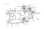
- FIG. 3 is a perspective view of the guide roller unit of FIG. 2 as viewed from the slide door toward the vehicle body.
- FIG. 3 is a perspective view of the guide roller unit of FIG. 2 as viewed from a vehicle body toward a slide door.
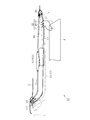
- the schematic block diagram of a slide door apparatus provided with the guide roller unit of FIG. FIG. 3 is a side view of the guide roller unit of FIG. 2 coupled to a center rail.
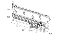
- the guide roller unit of FIG. 6 WHEREIN: The perspective view of the unit main body before assembly and a cable connection member. The enlarged perspective view of the unit main body of FIG.
- FIG. 7 The top view of the unit main body of FIG. 7, and a cable connection member.
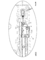
- (A) and (b) are explanatory drawings which each show the connection procedure of two drive cables with respect to the connection part provided in the cable connection member of FIG. (A)
- (b) is explanatory drawing which respectively shows the detachment prevention structure of two drive cables of Fig.11 (a) and FIG.11 (b).
- the vehicle 1 of the present embodiment opens and closes the door opening 3 provided on the side surface (the vehicle body side surface 2a) of the vehicle body 2 by moving in the vehicle longitudinal direction (left and right direction in FIG. 1).
- the vehicle longitudinal direction left and right direction in FIG. 1
- a plurality of guide rails 10 extending in the front-rear direction are provided on the vehicle body side surface 2a.
- the guide rail 10 includes a center rail 11, an upper rail 12 and a lower rail 13 provided on the rear, upper edge and lower edge (right side, upper side and lower side in FIG. 1) of the door opening 3, respectively.
- guide roller units 21 to 23 having guide rollers 20 capable of rolling on the tracks (T1, T2) formed by the guide rails 10 are respectively connected.
- the guide roller units 21 to 23 support the slide door 4 on the vehicle body 2 (specifically, the guide rail 10), and allow the slide door 4 to move back and forth along the extension direction of the guide rail 10.
- the slide door 4, the guide rail 10 and the guide roller units 21 to 23 form a slide door device 30.
- a groove-shaped recess 31 extending in the vehicle front-rear direction (in FIG. 2, a direction perpendicular to the paper surface) is formed in the vehicle body side surface 2a behind the door opening 3.
- the center rail 11 is disposed in the recess 31 so as to have a substantially channel-shaped cross section that opens in the vehicle exterior direction (left side in FIG. 2).
- the center rail 11 has a side wall 11a extending along the bottom surface 31a of the recess 31, and an upper wall 11b and a lower wall extending from the upper end and the lower end of the side wall 11a to the outside of the vehicle and facing each other. 11c and an outer wall 11d facing the side wall 11a.
- the guide roller unit 21 includes a plurality of guide rollers 20 rolling on the tracks T1 and T2 formed by the lower wall portion 11c and the inner wall surface of the outer wall portion 11d (or the side wall portion 11a).
- the guide roller unit 21 includes a support arm 40, which supports the guide roller 20 and has one end (tip) coupled to the center rail 11 and the slide door 4. And the other end (proximal end) to be connected.
- the support arm 40 is formed by plastic working (bending) of a metal plate.
- the support arm 40 has an arm portion 41 whose plate surface faces the vertical direction of the vehicle (vertical direction in FIG. 2), and the plate surface faces the lateral direction of the vehicle (horizontal direction in FIG. 2) And an upright portion 42 extending upward from one end of the arm portion 41, and a substantially L-shaped plate-like portion.
- the guide rollers 20 are provided at the upper end portion of the standing portion 42.
- a support shaft 43 is provided at the upper end portion of the standing portion 42.
- the support shaft 43 penetrates the standing portion 42 and extends toward the vehicle side surface 2 a.
- a pair of flange portions 44 extending from the upper end of the standing portion 42 toward the vehicle side surface 2a ing.
- the support shafts 45 extending in the vertical direction are provided on the flanges 44 so as to penetrate the flanges 44 in the thickness direction.
- the guide roller unit 21 includes a load roller 46 supported by one support shaft 43 and a pair of vertical rollers 47 supported by two support shafts 45 respectively.
- the load roller 46 is rotatably supported on the side (right side in FIG. 2) opposite to the side surface 2 a of the standing portion 42. Further, each vertical roller 47 is rotatably supported above the corresponding flange portion 44.
- the load roller 46 is disposed between the upper wall 11b and the lower wall 11c, and each vertical roller 47 is disposed between the side wall 11a and the outer wall 11d. Are connected to the center rail 11.
- the load roller 46 rolls on a track T1 formed by the lower wall 11c of the center rail 11, and each vertical roller 47 rolls on a track T2 formed by the outer wall 11d (or the side wall 11a).
- the guide roller unit 21 can move along the extending direction of the center rail 11.
- the load roller 46 has a wheel diameter larger than the gap formed between the outer end of the lower wall 11 c and the lower end of the outer wall 11 d.
- Each vertical roller 47 has a wheel diameter slightly smaller than the distance between the side wall 11a and the outer wall 11d.
- the support arm 40 is disposed between the vehicle body 2 and the slide door 4, and a guide roller unit 21 is provided at the base end (the end on the left side in FIG. 2) of the support arm 40.
- a door connecting portion 50 which can connect the slide door 4 while allowing relative rotation around a rotation axis L extending in the vertical direction.
- the support arm 40 includes a side plate 51 extending upward from a side end of an arm 41 extending in a direction intersecting the vehicle body 2 and the slide door 4.
- the upper end of the side plate portion 51 is provided with a connecting flange 52 extending opposite to the arm portion 41 so as to be substantially parallel to the arm portion 41.
- the connecting flange 52 and the arm portion 41 are respectively formed with circular holes 53 and 54 which are coaxial with and face each other.
- the door connecting portion 50 is formed by inserting the shaft-like member 55 having the rotation axis L into the circular holes 53 and 54.
- the slide door 4 is in a fully closed position (the position shown by a two-dot chain line in FIG. 5) closing the door opening 3 and a vehicle rear (right side in FIG. 5) than the fully closed position. It is movable between fully open positions. In the fully closed position, the slide door 4 is arranged such that the outer surface (design surface) of the slide door 4 is substantially flush with the side surface 2 a on which the center rail 11 is provided. In addition, when the slide door 4 moves from the fully closed position to the rear of the vehicle, as shown by the solid line in FIG. 5, the slide door 4 is outside in the vehicle width direction than the vehicle side 2a so as not to interfere with the vehicle side 2a. In FIG. 5, the lower side is disposed. Such an opening / closing operation of the slide door 4 is secured by curving the vehicle front portion of each guide rail 10 toward the inner side in the vehicle width direction (the upper side in FIG. 5).
- the guide roller unit 21 When the guide roller unit 21 passes the curved portion of the guide rail 10 (center rail 11), the guide roller unit 21 rotates with respect to the slide door 4 around the rotation axis L of the door connecting portion 50. It has become. Thus, the slide door 4 can be maintained in a substantially parallel state with respect to the vehicle body side surface 2a regardless of the operating position.
- the slide door device 30 includes two drive cables 61 and 62 arranged along the extension direction of the center rail 11. Further, the end 61e of the drive cable 61 and the end 62e of the drive cable 62 are connected to the guide roller unit 21 from opposite directions. The slide door device 30 can open and close the slide door 4 by pulling the guide roller unit 21 through the drive cables 61 and 62.
- the slide door device 30 uses a motor (not shown) as a drive source to wind one of the drive cables 61 and 62 while drawing out the other. Is equipped.
- the drum device 63 is disposed in the vehicle body 2 in the vicinity of the center rail 11 and has a drum accommodating portion 63 a disposed at a substantially central portion in the longitudinal direction of the center rail 11.
- Connected to the drum device 63 are two guide tubes 65 and 66 extending forward and backward of the vehicle.
- the drive cables 61 and 62 pass through the guide tubes 65 and 66, respectively, in the vicinity of the front end 11f (near the end on the left side in FIG. 5) and in the vicinity of the rear end 11r (in FIG. 5). It is pulled out near the end).
- Pulleys 67 and 68 are provided in the vicinity of the front end 11 f and the rear end 11 r of the center rail 11, respectively.
- the drive cables 61 and 62 are respectively routed along the extension direction of the center rail 11 by being wound around these pulleys 67 and 68.
- the first drive cable 61 drawn out near the front end 11 f of the center rail 11 through the guide tube 65 is wound around the pulley 67 so as to be along the extending direction of the center rail 11. It is wired from the front end 11 f to the rear end 11 r.
- the second drive cable 62 drawn out near the rear end 11 r of the center rail 11 through the guide tube 66 is wound around the pulley 68 so that the second drive cable 62 follows the extension direction of the center rail 11. It is routed from the end 11r to the front end 11f.
- the first drive cable 61 is routed below the center rail 11, and the second drive cable 62 is routed inside the center rail 11.
- the end portion 61e of the first drive cable 61 does not interfere with the first drive cable 61 and the second drive cable 62, and the guide roller unit from the side corresponding to the front end 11f of the center rail 11
- the end 62 e of the second drive cable 62 is connected to the guide roller unit 21 from the side corresponding to the rear end 11 r of the center rail 11.
- the guide roller unit 21 pulled by the drive cable 61 moves toward the front end 11 f of the center rail 11.
- the guide roller unit 21 pulled by the drive cable 62 moves toward the rear end 11 r of the center rail 11.
- the guide roller unit 21 includes a unit main body 70 capable of supporting the slide door 4 on the vehicle body 2 and a cable connection member 80 formed separately from the unit main body 70. ing.
- the unit body 70 includes the support arm 40 and a plurality of guide rollers 20.
- connection work of the drive cables 61 and 62 to the guide roller unit 21 is performed at the rear end 11 r of the center rail 11. That is, the unit body 70 is already interposed between the slide door 4 and the center rail 11. Further, the two drive cables 61 and 62 arranged from opposite directions along the extension direction of the center rail 11 are connected to the cable connection member 80 in advance. Then, the connection work of the drive cables 61 and 62 is completed by fastening the cable connection member 80 to the unit main body 70.
- the cable connection member 80 of the present embodiment is formed by plastic working (bending) of a metal plate, similarly to the support arm 40.
- the cable connecting member 80 includes a base portion 81 and a vertical wall portion 82 which form a substantially L-shaped plate-like portion similar to the arm portion 41 and the standing portion 42 of the support arm 40.
- the cable connecting member 80 is disposed on the unit main body 70 such that the base 81 is disposed below the arm 41 and the vertical wall 82 is disposed on the inner side in the vehicle width direction of the standing portion 42 (right side in FIG. 10). It is assembled against.
- the arm portion 41 of the unit main body 70 and the base 81 of the cable connection member 80 intersect (substantially orthogonal) with the extending direction of the center rail 11 (in FIG. It arrange
- the arm portion 41 of the support arm 40 and the base portion 81 of the cable connection member 80 are provided with fastening portions or fastening flanges 83 and 84 for fastening the both.
- fastening flanges 83 and 84 are respectively upward from the side end of the arm 41 and the side end of the base 81 arranged on the side (the lower side in FIG. 9) corresponding to the rear end 11 r of the center rail 11 (see FIG. In 10, it extends toward the upper side).
- a screw hole 86 which is screwed to a fastening bolt 85 is formed in the fastening flange 83 of the unit main body 70.
- the fastening flange 84 of the cable connection member 80 is formed with a through hole 87 through which the bolt 85 is inserted.
- the screw holes 86 and the through holes 87 function as fastening holes.
- the fastening flanges 83 and 84 of the two are arranged in a state of being superimposed on each other in the direction along the extension direction of the center rail 11.
- the unit body 70 and the cable connection member 80 are fixed.
- the cable connection member 80 is provided with a flange portion 88 extending from the upper end of the vertical wall portion 82 toward the vehicle side 2a (right side in FIGS. 9 and 10) in the assembled state with respect to the unit main body 70.
- the flange portion 88 is formed with a substantially circular fitting hole 89 having a diameter substantially equal to (slightly larger than) the support shaft 45 of the vertical roller 47 provided in the unit main body 70.
- the flange portion 88 is arranged below the flange portion 44 of the unit main body 70 in a state where the support shaft 45 of the vertical roller 47 is inserted into the fitting hole 89.
- the lower end side portion of the vertical wall portion 82 of the cable connection member 80 is bifurcated.
- One of the bifurcated portions forms the base 81.
- the other of the bifurcated portions forms a flange portion 90 extending toward the vehicle body side surface 2a in the assembled state, like the flange portion 88 provided at the upper end of the vertical wall portion 82.
- the drive cables 61 and 62 are respectively connected to the flanges 88 and 90 disposed to face each other in the vertical direction.
- the guide roller unit 21 is provided at the flange portion (lower flange portion) 90 provided at the lower end of the vertical wall portion 82.
- a connecting portion 91 is provided to be connected to a first drive cable 61 for pulling the front rail 11 toward the front end 11 f (left side in FIG. 11) of the center rail 11.
- a second drive for pulling the guide roller unit 21 toward the rear end 11r (right side in FIG. 11) of the center rail 11 in the flange portion (upper flange portion) 88 provided at the upper end of the vertical wall portion 82.
- a connecting portion 92 connected to the cable 62 is provided.
- connection parts 91 and 92 have a hook shape (hook shape). Specifically, the wedge-shaped tips of the connection portions 91 and 92 face in the direction opposite to the pulling direction by the corresponding drive cables 61 and 62, respectively. In the end portions 61e and 62e of the drive cables 61 and 62, connection holes 93 and 94 which can be fitted to these connection portions 91 and 92, respectively, are formed.
- the drive cables 61 and 62 connect the connection holes 93 and 94 formed in the end portions 61e and 62e respectively from the side opposite to the pulling direction.
- the cable connection member 80 is connected by being fitted in the hook shape of the portions 91 and 92.
- the end portions 61e and 62e of the drive cables 61 and 62 are rotated by the predetermined angles ⁇ 1 and ⁇ 2 so as to follow the wedge shape of the connection portions 91 and 92, respectively.
- the extension direction and the pulling direction of the drive cables 61 and 62 coincide with each other, and the drive cables 61 and 62 can be guided by the guide roller unit 21 without the ends 61e and 62e being detached from the corresponding connection parts 91 and 92. Can be stably towed.
- the upper flange portion 88 is disposed in the center rail 11, and the lower flange portion 90 is disposed below the center rail 11. It is concluded. As shown in FIGS. 12 (a) and 12 (b), in this fastened state, the end portions 61e, 62e of the drive cables 61, 62 connected to the flange portions 88, 90 are the center rail 11 or By interfering with the side surface 2a of the vehicle body, the operation of detaching from the connection portions 91 and 92 is restricted.
- the end 61e of the first drive cable 61 arranged below the center rail 11 has a predetermined angle with respect to the pulling direction (left direction in FIG. 12).
- the vehicle side surface 2a is interfered.
- the end 62e of the second drive cable 62 wired in the center rail 11 is connected at a predetermined angle ⁇ 4 from the pulling direction (rightward in FIG. 12).
- the center rail 11 interferes with (the fastening member of) the center rail 11.
- the predetermined angles ⁇ 3 and ⁇ 4 for permitting rotation of the end portions 61e and 62e are set to values smaller than the predetermined angles ⁇ 1 and ⁇ 2 required for detachment from the corresponding connection portions 91 and 92, respectively. By doing this ( ⁇ 1> ⁇ 3, ⁇ 2> ⁇ 4), detachment of the drive cables 61 and 62 is suppressed.
- the cable connection member 80 in a state in which the drive cables 61 and 62 are connected to the unit main body 70 in a state of being connected to the center rail 11 is a rear end 11 r of the center rail 11. It assembles along the extending direction from the corresponding side. At this time, the upper flange portion 88 to which the second drive cable 62 is connected is disposed in the center rail 11. Then, when the fastening flange 83 of the unit main body 70 and the fastening flange 84 of the cable connection member 80 abut, the assembly position in the direction along the extension direction of the center rail 11 is determined.
- the cable connection member 80 is moved upward.
- the support shaft 45 of the vertical roller 47 is inserted into the fitting hole 89 formed in the upper flange portion 88.
- the arm portion 41 of the support arm 40 and the base 81 of the cable connection member 80 abut, and the assembly position in the vehicle vertical direction substantially orthogonal to the extending direction of the center rail 11 is determined.
- the support arm 40 (the arm portion 41 and the standing portion 42) of the unit main body 70 and the cable connection member 80 (the base 81 and the vertical wall portion 82) are brought into contact with each other. It is possible to align the screw hole 86 and the through hole 87 of the fastening flange 84. By screwing a bolt 85 into the screw hole 86 through the through hole 87 and tightening the bolt 85, the cable connection member 80 is fixed to the unit main body 70. Thus, the operation of connecting the drive cables 61 and 62 to the guide roller unit 21 is completed.
- the tension adjustment of the drive cables 61 and 62 is performed after the connection operation to the guide roller unit 21 as described above.
- the guide roller unit 21 can be pulled by the drive cables 61 and 62.
- a unit body that supports the slide door 4 on the vehicle body 2 by having a plurality of guide rollers 20 capable of rolling on the tracks T1 and T2 formed by the guide rails 10 (center rail 11). 70 is provided. Further, the guide roller unit 21 includes a cable connection member 80 formed separately from the unit main body 70. Two drive cables 61 and 62 arranged along the extending direction of the center rail 11 are connected to the cable connecting member 80 from opposite directions. The cable connection member 80 is fixed to the unit body 70 by fastening.
- the cable connection member 80 is fastened to the unit body 70 in the direction along the extension direction of the center rail 11. That is, the gap between the vehicle body 2 as the work space and the slide door 4 opens in the extending direction of the center rail 11 extending in the longitudinal direction of the vehicle. Therefore, according to the above configuration, the cable connection member 80 can be easily fastened to the unit body 70.
- the unit body 70 is provided with a fastening flange 83 having a screw hole 86 screwed with the bolt 85 for fastening
- the cable connection member 80 is a fastening flange having a through hole 87 through which the bolt 85 is inserted.
- the fastening flanges 83 and 84 abut each other in the direction along the extension direction of the center rail 11.
- the support arm 40 of the unit main body 70 and the cable connection member 80 are each formed by plastic working (bending) of a metal plate. Furthermore, the support arm 40 and the cable connection member 80 respectively have positioning portions (the arm portion 41 and the standing portion 42 of the support arm 40 and the cable connection member 80) having a substantially L-shaped bent plate shape.
- the base portion 81 and the vertical wall portion 82) are provided.
- the unit main body 70 and the cable connection member 80 are assembled in such a manner that their positioning portions abut on each other in two directions (vehicle inward and outward directions and up and down directions) intersecting with the extending direction of the center rail 11.
- the cable connection member 80 can be positioned with respect to the unit main body 70 easily and reliably. As a result, since the positioning between the fastening holes (the screw holes 86 and the through holes 87) becomes possible, the cable connection member 80 can be more easily fastened to the unit main body 70.
- the cable connection member 80 is provided with a fitting hole 89 that functions as an engaging portion that engages with the support shaft 45 of the vertical roller 47 (guide roller 20). That is, the support shaft 45 of the vertical roller 47 extends in a direction substantially orthogonal (intersecting) to the extending direction of the center rail 11, that is, the fastening direction of the unit body 70 and the cable connecting member 80. Therefore, according to the above configuration, the cable connection member 80 can be easily positioned with respect to the unit main body 70 by utilizing the engagement relationship between the support shaft 45 and the fitting hole 89.
- the relative rotation between the cable connection member 80 and the unit main body 70 is restricted by the function of the fitting hole 89 and the support shaft 45 which engage with each other as the rotation preventing portion. Be done.
- the cable connection member 80 can be more easily fastened to the unit body 70.
- the cable connection member 80 includes flanges 88 and 90 provided at the upper end and the lower end of the vertical wall 82.
- the connection parts 91 and 92 to which the drive cables 61 and 62 are connected are provided on the flange parts 88 and 90, respectively.
- the drive cables 61 and 62 can be connected to the cable connection member 80 in a suitable state in which the drive cables 61 and 62 do not interfere with each other. Thereby, smooth operation of the guide roller unit 21 can be secured.
- connection member 80 is provided with connection portions 91 and 92 having a hook shape. Further, connection holes 93 and 94 are formed in the end portions 61e and 62e of the drive cables 61 and 62 respectively, and the connection holes 93 and 94 are the end portions 61e and 62e of the connection portions 91 and 92 along the wedge shape. It functions as a fitting part fitted to the connection parts 91 and 92 while permitting movement (rotation).
- the end portions 61e and 62e of the drive cables 61 and 62 operate in the direction of detaching from the corresponding connection portions 91 and 92, the end portions 61e and 62e interfere with the center rail 11 or the vehicle body side surface 2a. Thus, the operation of the end portions 61e and 62e that are detached from the connection portions 91 and 92 is restricted.
- connection work of the drive cables 61 and 62 can be performed more easily. And effectively, detachment of the drive cables 61 and 62 connected to the guide roller unit 21 can be suppressed.
- the drive cables 61 and 62 are connected to the guide roller unit 21 connected to the center rail 11.
- the drive cables 61 and 62 may be connected to guide roller units (22 and 23) connected to the guide rails 10 provided at other places such as the upper rail 12 and the lower rail 13 and the like.
- connection portions 91 and 92 to which the drive cables 61 and 62 are connected may not necessarily be provided on the flange portions 88 and 90.
- connection form between the drive cables 61 and 62 and the connection parts 91 and 92 may be changed.
- the connection portions 91 and 92 may have a hole shape, and the end portions 61e and 62e of the drive cables 61 and 62 may have a hook shape.
- both may be bowl-shaped.
- connection forms other than fitting such as hooking and fastening (screwing) may be employed.
- the first drive cable 61 for pulling the guide roller unit 21 toward the front end 11 f of the center rail 11 is disposed below the center rail 11 and moves the guide roller unit 21 toward the rear end 11 r.
- the second drive cable 62 to be pulled is routed in the center rail 11.
- the arrangement position of the drive cables 61 and 62 may be changed.
- the first drive cable 61 may be routed in the center rail 11 and the second drive cable 62 may be routed below the center rail 11.
- Both the drive cables 61 and 62 may be arranged in the center rail 11 or may be arranged outside the center rail 11.
- the support shaft 45 of the vertical roller 47 is inserted into the fitting hole 89 formed in the cable connection member 80, so that the fitting holes 89 engage with each other when performing the fastening operation.
- the support shaft 45 function as a rotation stop.
- the present invention is not limited to this, and the cable connecting member 80 may be provided with an engagement hole into which the support shaft 43 of the load roller 46 is inserted.
- the engaging portion of the cable connection member 80 may not necessarily be a hole, such as a recess, a notch, or a wall.
- the configuration of the rotation preventing portion may be arbitrarily changed, such as not using the support shaft of the guide roller 20.
- the fastening direction of the cable connection member 80 with respect to the unit main body 70 is the direction along the extending direction of the center rail 11, but a configuration in which fastening is performed from other directions may be adopted.
- the positioning portion (arm portion 41) of the support arm 40 and the positioning portion (base 81) of the cable connection member 80 abut each other in the vehicle vertical direction substantially orthogonal to the extending direction of the guide rail.
- the positioning portion (the standing portion 42) of the support arm 40 and the positioning portion (the vertical wall portion 82) of the cable connection member 80 are in contact with each other in the inside and outside directions substantially orthogonal to the extending direction of the guide rail.
- the present invention is not limited to this, and the “extending direction of the guide rail” and the “two directions” crossing this may not necessarily be orthogonal to each other.
- the positioning portion of the support arm 40 and the positioning portion of the cable connecting member 80 may be in contact with each other in one direction intersecting the extending direction of the guide rail. Even with such a configuration, both of them can be positioned in the extending direction of the center rail 11.
Landscapes
- Engineering & Computer Science (AREA)
- Mechanical Engineering (AREA)
- Power-Operated Mechanisms For Wings (AREA)
- Platform Screen Doors And Railroad Systems (AREA)
- Closing And Opening Devices For Wings, And Checks For Wings (AREA)
Abstract
ガイドローラユニットは、ガイドレールが形成する軌道上を転動可能なガイドローラを有して車体にスライドドアを支持するユニット本体と、締結により前記ユニット本体に対して固定されるケーブル接続部材であって、前記ガイドレールの延伸方向に沿って配索される二本の駆動ケーブルが互いに相反する方向から接続される、前記ケーブル接続部材と、を備える。
Description
本発明は、ガイドローラユニット及び車両用スライドドア装置に関するものである。
通常、車両用のスライドドア装置は、ガイドレールが形成する軌道上を転動するガイドローラを有して車体にスライドドアを支持するガイドローラユニットを備えている。例えば、特許文献1に記載のスライドドア装置では、ガイドローラユニットに対し、ガイドレールの延伸方向に沿う方向に配索された二本の駆動ケーブルが互いに相反する方向から接続されている。そして、これら駆動ケーブルを牽引することにより、スライドドアをガイドレールの延伸方向に移動させることが可能となっている。
このようなスライドドア装置において、ガイドローラユニットは、車体とスライドドアとの間の狭い隙間に配置される。このため、ガイドローラユニットに各駆動ケーブルを接続する作業は極めて煩雑なものとなっている。そして、これが組付作業の効率化を妨げる一因になっていることから、この点において、なお改善の余地を残すものとなっている。
本発明の目的は、より容易に駆動ケーブルの接続作業を行うことのできるガイドローラユニット及び車両用スライドドア装置を提供することにある。
上記課題を解決するガイドローラユニットは、ガイドレールが形成する軌道上を転動可能なガイドローラを有して車体にスライドドアを支持するユニット本体と、締結により前記ユニット本体に対して固定されるケーブル接続部材であって、前記ガイドレールの延伸方向に沿って配索される二本の駆動ケーブルが互いに相反する方向から接続される、前記ケーブル接続部材と、を備える。
以下、本発明の一実施形態を図面に従って説明する。
図1に示すように、本実施形態の車両1は、車両前後方向(図1中、左右方向)に移動することにより車体2の側面(車体側面2a)に設けられたドア開口部3を開閉可能なスライドドア4を備えている。
図1に示すように、本実施形態の車両1は、車両前後方向(図1中、左右方向)に移動することにより車体2の側面(車体側面2a)に設けられたドア開口部3を開閉可能なスライドドア4を備えている。
詳述すると、車体側面2aには、前後方向に延びる複数のガイドレール10が設けられている。ガイドレール10は、ドア開口部3の後方、上縁部及び下縁部(図1中、右側、上側及び下側)にそれぞれ設けられたセンターレール11、アッパレール12及びロアレール13を含む。また、これらのガイドレール10(11~13)には、当該ガイドレール10が形成する軌道(T1,T2)上を転動可能なガイドローラ20を有したガイドローラユニット21~23がそれぞれ連結されている。これらのガイドローラユニット21~23は、車体2(詳しくはガイドレール10)にスライドドア4を支持して、ガイドレール10の延伸方向に沿ったスライドドア4の前後移動を可能とする。スライドドア4、ガイドレール10及びガイドローラユニット21~23は、スライドドア装置30を形成している。
図1及び図2に示すように、ドア開口部3の後方の車体側面2aには、車両前後方向(図2中、紙面に直交する方向)に延びる溝状の凹部31が形成されている。センターレール11は、車外方向(図2中、左側)に開口する断面略チャネル形状を有して、この凹部31内に配置されている。
センターレール11は、凹部31の底面31aに沿って延びる側壁部11aと、この側壁部11aの上端及び下端から車外方向に延在するとともに互いに対向して配置された上壁部11b及び下壁部11cと、側壁部11aに対向する外壁部11dと、を備えている。ガイドローラユニット21は、下壁部11c及び外壁部11d(又は側壁部11a)の内壁面が形成する軌道T1,T2上を転動する複数のガイドローラ20を備えている。
図2~図4に示すように、ガイドローラユニット21は支持アーム40を備え、支持アーム40は、ガイドローラ20を支持してセンターレール11に連結される一端(先端)と、スライドドア4に連結される他端(基端)とを有する。
本実施形態では、この支持アーム40は、金属板を塑性加工(折曲加工)することにより形成されている。具体的には、支持アーム40は、その板面が車両上下方向(図2中、上下方向)を向く腕部41と、その板面が車両内外方向(図2中、左右方向)を向くように腕部41の一端から上方に向かって延びる立設部42と、を備えた略L字型の板状部を有している。そして、上記各ガイドローラ20は、その立設部42の上端部分に設けられている。
具体的には、立設部42の上端部分には支持軸43が設けられている。支持軸43は、立設部42を貫通し、車体側面2aに向かって延びている。また、センターレール11の延伸方向(図2中、紙面に直交する方向)における支持軸43の両側には、立設部42の上端から車体側面2aに向かって延びる一対のフランジ部44が設けられている。これらのフランジ部44には、これらのフランジ部44を厚み方向に貫通する態様で上下方向に延びる支持軸45がそれぞれ設けられている。ガイドローラユニット21は、一つの支持軸43に軸支されたロードローラ46と、二つの支持軸45にそれぞれ軸支された一対の垂直ローラ47とを備えている。
図2に示すように、ロードローラ46は、立設部42の車体側面2aに対向する側(図2中、右側)において回転自在に支持されている。また、各垂直ローラ47は、対応するフランジ部44の上方において回転自在に支持されている。ロードローラ46が上壁部11bと下壁部11cとの間に配置され、各垂直ローラ47が側壁部11aと外壁部11dとの間に配置された状態で、支持アーム40の立設部42がセンターレール11に対して連結されるようになっている。
ロードローラ46は、センターレール11の下壁部11cが形成する軌道T1上を転動し、各垂直ローラ47は、外壁部11d(又は側壁部11a)が形成する軌道T2上を転動する。ガイドローラユニット21は、これにより、センターレール11の延伸方向に沿って移動することが可能となっている。
ロードローラ46は、下壁部11cの車外側端部と外壁部11dの下端部との間に形成される隙間よりも大きな車輪径を有している。また、各垂直ローラ47は、側壁部11aと外壁部11dとの間の間隔よりも僅かに小さな車輪径を有している。これにより、これらのガイドローラ20(46,47)を介してセンターレール11に連結されたガイドローラユニット21が、センターレール11から脱離しないように構成されている。
図2~図4に示すように、支持アーム40は車体2とスライドドア4との間に配置され、支持アーム40の基端(図2中、左側の端部)には、ガイドローラユニット21に対してスライドドア4を、上下方向に延びる回動軸線L周りの相対回動を許容しつつ連結可能なドア連結部50が形成されている。
具体的には、支持アーム40は、車体2及びスライドドア4に対して交差する方向に延びる腕部41の側端から上方に向かって延びる側板部51を備えている。この側板部51の上端には、腕部41と略平行となるように当該腕部41に対向して延びる連結フランジ52が設けられている。連結フランジ52及び腕部41には、それぞれ、互いに同軸で且つ対向する円孔53,54が形成されている。これらの円孔53,54に対して上記回動軸線Lを有する軸状部材55を挿通することにより、ドア連結部50が形成されるようになっている。
図5に示すように、スライドドア4は、ドア開口部3を閉じる全閉位置(図5中、二点鎖線に示す位置)と、全閉位置よりも車両後方(図5中、右側)の全開位置との間を移動可能である。スライドドア4は、全閉位置においては、センターレール11が設けられた車体側面2aに対してスライドドア4の外面(意匠面)が略面一となるように配置される。また、スライドドア4は、全閉位置から車両後方に移動した場合には、図5中に実線で示すように、車体側面2aに干渉しないように、その車体側面2aよりも車幅方向外側(図5中、下側)に配置される。各ガイドレール10の車両前側部分を車幅方向内側(図5中、上側)に向かって湾曲させることによって、スライドドア4のこのような開閉動作が担保されている。
ガイドレール10(センターレール11)の上記湾曲部分をガイドローラユニット21が通過する際、上記ドア連結部50の回動軸線L周りに当該ガイドローラユニット21がスライドドア4に対して回動するようになっている。これにより、スライドドア4は、その動作位置に関わらず、車体側面2aに対して略平行に配置された状態に維持されることが可能となっている。
図3~図5に示すように、スライドドア装置30は、センターレール11の延伸方向に沿って配索された二本の駆動ケーブル61,62を備えている。また、駆動ケーブル61の端部61eと駆動ケーブル62の端部62eとは、互いに相反する方向から上記ガイドローラユニット21に接続されるようになっている。スライドドア装置30は、これらの駆動ケーブル61,62を介してガイドローラユニット21を牽引することにより、スライドドア4を開閉動作させることが可能となっている。
詳述すると、図5に示すように、本実施形態のスライドドア装置30は、図示しないモータを駆動源として上記駆動ケーブル61,62の一方を巻き取るとともに他方を繰り出すことが可能なドラム装置63を備えている。
ドラム装置63はセンターレール11近傍の車体2内に配置され、センターレール11の長手方向略中央部分に配置されるドラム収容部63aを有している。このドラム装置63には、車両前方及び後方に向かって延びる二本のガイドチューブ65,66が接続されている。上記駆動ケーブル61,62は、それぞれ、これらのガイドチューブ65,66を通ってセンターレール11の前端11f近傍(図5中、左側の端部近傍)及び後端11r近傍(図5中、右側の端部近傍)に引き出されるようになっている。
センターレール11の前端11f及び後端11rの近傍には、それぞれ、プーリー67,68が設けられている。駆動ケーブル61,62は、それぞれ、これらのプーリー67,68に巻き掛けられることにより、センターレール11の延伸方向に沿って配索されるようになっている。
具体的には、ガイドチューブ65を通ってセンターレール11の前端11f近傍に引き出された第1の駆動ケーブル61は、プーリー67に巻き掛けられることにより、センターレール11の延伸方向に沿うようにして前端11fから後端11rに向かって配索されている。同様に、ガイドチューブ66を通ってセンターレール11の後端11r近傍に引き出された第2の駆動ケーブル62は、プーリー68に巻き掛けられることにより、センターレール11の延伸方向に沿うようにして後端11rから前端11fに向かって配索されている。第1の駆動ケーブル61は、センターレール11の下方に配索され、第2の駆動ケーブル62は、センターレール11内に配索されている。これにより、第1の駆動ケーブル61と第2の駆動ケーブル62とが互いに干渉することなく、第1の駆動ケーブル61の端部61eは、センターレール11の前端11fに対応する側からガイドローラユニット21に対して接続され、第2の駆動ケーブル62の端部62eは、センターレール11の後端11rに対応する側からガイドローラユニット21に対して接続されるようになっている。
ドラム装置63が第1の駆動ケーブル61を巻き取ることにより、その駆動ケーブル61に牽引されたガイドローラユニット21がセンターレール11の前端11fに向かって移動する。また、ドラム装置63が第2の駆動ケーブル62を巻き取ることにより、その駆動ケーブル62に牽引されたガイドローラユニット21がセンターレール11の後端11rに向かって移動する。これにより、ガイドローラユニット21に支持されたスライドドア4を開閉動作させることが可能となっている。
(駆動ケーブルの接続構造)
次に、ガイドローラユニット21における駆動ケーブル61,62の接続構造について説明する。
次に、ガイドローラユニット21における駆動ケーブル61,62の接続構造について説明する。
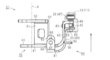
図6~図8に示すように、ガイドローラユニット21は、車体2にスライドドア4を支持可能なユニット本体70と、このユニット本体70とは別体に形成されたケーブル接続部材80とを備えている。ユニット本体70は、前記支持アーム40及び複数のガイドローラ20を含む。
ガイドローラユニット21に対する駆動ケーブル61,62の接続作業は、センターレール11の後端11rにおいて行われる。即ち、ユニット本体70は、既にスライドドア4とセンターレール11との間に介在されている。また、センターレール11の延伸方向に沿って互いに相反する方向から配索された両駆動ケーブル61,62は、それぞれ、予めケーブル接続部材80に対して接続されている。そして、このケーブル接続部材80をユニット本体70に対して締結することにより、駆動ケーブル61,62の接続作業が完了する。
図8~図10に示すように、本実施形態のケーブル接続部材80は、支持アーム40と同様、金属板を塑性加工(折曲加工)することにより形成されている。このケーブル接続部材80は、支持アーム40の腕部41及び立設部42と類似した、略L字型の板状部を形成する基部81及び縦壁部82を備えている。ケーブル接続部材80は、基部81が腕部41の下方に配置され、縦壁部82が立設部42の車幅方向内側(図10中、右側)に配置されるように、ユニット本体70に対し組み付けられる。このとき、ユニット本体70の腕部41とケーブル接続部材80の基部81とは、センターレール11の延伸方向(図10中、紙面前後方向)に交差(略直交)する方向、即ち上下方向において、互いに重ね合わされた状態で配置される。また、ユニット本体70の立設部42とケーブル接続部材80の縦壁部82とは、センターレール11の延伸方向に交差(略直交)する方向、即ち車両内外方向において、互いに重ね合わされた状態で配置される。支持アーム40の腕部41及びケーブル接続部材80の基部81には、それぞれ、両者を締結するための締結部すなわち締結フランジ83,84が設けられている。
これらの締結フランジ83,84は、それぞれ、センターレール11の後端11rに対応する側(図9中、下側)に配置される腕部41の側端及び基部81の側端から上方(図10中、上側)に向かって延びている。ユニット本体70の締結フランジ83には、締結用のボルト85に螺合する螺子孔86が形成されている。ケーブル接続部材80の締結フランジ84には、そのボルト85が挿通される貫通孔87が形成されている。螺子孔86及び貫通孔87は締結用の孔部として機能する。
上記のようにユニット本体70に対してケーブル接続部材80を組み付けることにより、両者の締結フランジ83,84は、センターレール11の延伸方向に沿う方向において互いに重ね合わされた状態で配置される。これらの両締結フランジ83,84をボルト85で締結することにより、ユニット本体70とケーブル接続部材80とが固定される。
また、ケーブル接続部材80は、ユニット本体70に対する組付状態において、縦壁部82の上端から車体側面2a(図9及び図10中、右側)に向かって延びるフランジ部88を備えている。このフランジ部88には、ユニット本体70に設けられた垂直ローラ47の支持軸45と略等しい(僅かに大きい)直径を有した略円孔状の嵌合孔89が形成されている。この嵌合孔89内に垂直ローラ47の支持軸45が挿入された状態で、フランジ部88がユニット本体70のフランジ部44の下方に配置されるようになっている。
ケーブル接続部材80の縦壁部82の下端側部分は、二股に分かれている。この二股に分かれた部分の一方が上記基部81を形成する。また、その二股に分かれた部分の他方は、上記縦壁部82の上端に設けられたフランジ部88と同様、組付状態において車体側面2aに向かって延びるフランジ部90を形成している。図3及び図4に示すように、これら上下方向において互いに対向するように配置された両フランジ部88,90に対して、上記駆動ケーブル61,62がそれぞれ接続されるようになっている。
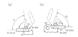
図3、図4、図11(a)、及び図11(b)に示すように、縦壁部82の下端に設けられたフランジ部(下側のフランジ部)90には、ガイドローラユニット21をセンターレール11の前端11f(図11中、左側)に向かって牽引する第1の駆動ケーブル61に接続される接続部91が設けられている。縦壁部82の上端に設けられたフランジ部(上側のフランジ部)88には、ガイドローラユニット21をセンターレール11の後端11r(図11中、右側)に向かって牽引する第2の駆動ケーブル62に接続される接続部92が設けられている。
これらの接続部91,92は、鈎形状(フック形状)を有している。具体的には、これらの接続部91,92の鈎形状の先端は、それぞれ、対応する駆動ケーブル61,62による牽引方向とは逆方向を向いている。駆動ケーブル61,62の端部61e,62eには、それぞれ、これらの接続部91,92に対して嵌合可能な接続孔93,94が形成されている。
図11(a)及び図11(b)に示すように、駆動ケーブル61,62は、それぞれ、その端部61e,62eに形成された接続孔93,94を、牽引方向とは反対側から接続部91,92の鈎形状に嵌合させることにより、ケーブル接続部材80に対して接続される。このとき、駆動ケーブル61,62の端部61e,62eは、それぞれ、接続部91,92の鈎形状に沿うように所定角度θ1,θ2ずつ回動させられる。これにより各駆動ケーブル61,62の延伸方向と牽引方向とが一致し、端部61e,62eが対応する接続部91,92から脱離することなく、各駆動ケーブル61,62がガイドローラユニット21を安定的に牽引できるようになっている。
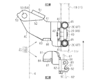
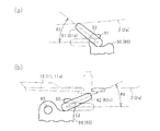
図8に示すように、ケーブル接続部材80は、上側のフランジ部88がセンターレール11内に配置され、下側のフランジ部90がセンターレール11の下方に配置された状態で、ユニット本体70に締結される。図12(a)及び図12(b)に示すように、この締結状態においては、これらのフランジ部88,90に接続された駆動ケーブル61,62の端部61e,62eが、センターレール11又は車体側面2aに干渉することによって、接続部91,92から脱離する動作が規制されるようになっている。
具体的には、図12(a)に示すように、センターレール11の下方に配索された第1の駆動ケーブル61の端部61eは、牽引方向(図12中、左方向)から所定角度θ3、接続時の回動方向(図11中、反時計周り方向)とは反対方向(図12中、時計周り方向)に回動することにより、車体側面2aに干渉する。また、図12(b)に示すように、センターレール11内に配索された第2の駆動ケーブル62の端部62eは、牽引方向(図12中、右方向)から所定角度θ4、接続時の回動方向(図11中、時計周り方向)とは反対方向(図12中、反時計周り方向)に回動することにより、センターレール11(の締結部材)に干渉する。本実施形態では、これら端部61e,62eの回動を許容する所定角度θ3,θ4を、それぞれ、対応する接続部91,92からの脱離に要する所定角度θ1,θ2よりも小さな値に設定することにより(θ1>θ3,θ2>θ4)、駆動ケーブル61,62の脱離が抑えられている。
次に、上記のように構成された本実施形態のガイドローラユニット21に対して駆動ケーブル61,62を接続する際の作業手順について説明する。
先ず、センターレール11の延伸方向に沿って延びる駆動ケーブル61,62の端部61e,62eを、それぞれ、互いに相反する配索方向からケーブル接続部材80に対して接続する(図11(a)及び図11(b)参照)。
先ず、センターレール11の延伸方向に沿って延びる駆動ケーブル61,62の端部61e,62eを、それぞれ、互いに相反する配索方向からケーブル接続部材80に対して接続する(図11(a)及び図11(b)参照)。
次に、図9に示すように、センターレール11に連結された状態のユニット本体70に対し、駆動ケーブル61,62が接続された状態のケーブル接続部材80が、センターレール11の後端11rに対応する側から延伸方向に沿って組み付けられる。このとき、第2の駆動ケーブル62が接続された上側のフランジ部88は、センターレール11内に配置される。そして、ユニット本体70の締結フランジ83とケーブル接続部材80の締結フランジ84とが当接することにより、センターレール11の延伸方向に沿う方向における組み付け位置が決定される。
また、図10に示すように、この状態で、ユニット本体70の支持アーム40の立設部42に対してケーブル接続部材80の縦壁部82を当接させる。これにより、センターレール11の延伸方向に対して略直交する車両内外方向における組み付け位置が決定される。
この状態からケーブル接続部材80を上方に移動させる。このとき、上側のフランジ部88に形成された嵌合孔89内に垂直ローラ47の支持軸45を挿入する。この上方移動によって、支持アーム40の腕部41とケーブル接続部材80の基部81とが当接し、センターレール11の延伸方向に対して略直交する車両上下方向における組み付け位置が決定される。
このようにしてユニット本体70の支持アーム40(の腕部41及び立設部42)とケーブル接続部材80(の基部81及び縦壁部82)とが当接させられることにより、締結フランジ83の螺子孔86と締結フランジ84の貫通孔87とを位置合わせすることが可能となっている。貫通孔87を通して螺子孔86にボルト85を螺着し、当該ボルト85を締め付けることにより、ユニット本体70に対してケーブル接続部材80が固定される。これによって、ガイドローラユニット21に対する駆動ケーブル61,62の接続作業が完了する。
駆動ケーブル61,62の張力調整は、このようなガイドローラユニット21に対する接続作業後に行われる。これにより、駆動ケーブル61,62によるガイドローラユニット21の牽引を行うことが可能となっている。
以上、本実施形態によれば、以下のような効果を得ることができる。
(1)ガイドローラユニット21は、ガイドレール10(センターレール11)が形成する軌道T1,T2上を転動可能な複数のガイドローラ20を有して車体2にスライドドア4を支持するユニット本体70を備える。また、ガイドローラユニット21は、ユニット本体70とは別体に形成されたケーブル接続部材80を備える。このケーブル接続部材80には、センターレール11の延伸方向に沿って配索された二本の駆動ケーブル61,62が互いに相反する方向から接続される。このケーブル接続部材80は、締結によりユニット本体70に対して固定される。
(1)ガイドローラユニット21は、ガイドレール10(センターレール11)が形成する軌道T1,T2上を転動可能な複数のガイドローラ20を有して車体2にスライドドア4を支持するユニット本体70を備える。また、ガイドローラユニット21は、ユニット本体70とは別体に形成されたケーブル接続部材80を備える。このケーブル接続部材80には、センターレール11の延伸方向に沿って配索された二本の駆動ケーブル61,62が互いに相反する方向から接続される。このケーブル接続部材80は、締結によりユニット本体70に対して固定される。
上記構成によれば、予め駆動ケーブル61,62が接続されたケーブル接続部材80をユニット本体70に締結することで、車体2とスライドドア4との間の隙間で行う作業を減らすことができる。これにより、より容易に駆動ケーブルの接続作業を行うことができる。
また、ユニット本体70とケーブル接続部材80とを別体に形成することで、ケーブル接続部材80の形状に関わらず、高い支持剛性を確保することができる。その結果、より好適に駆動ケーブル61,62を接続し且つ当該駆動ケーブル61,62によってガイドローラユニット21を牽引することが可能な最適形状を追求することが可能になる。
(2)ケーブル接続部材80は、センターレール11の延伸方向に沿う方向においてユニット本体70に締結される。即ち、作業スペースとなる車体2とスライドドア4との間の隙間は、車両前後方向に延びるセンターレール11の延伸方向に開口する。従って、上記構成によれば、容易に、ユニット本体70に対してケーブル接続部材80を締結することができる。
(3)ユニット本体70は、締結用のボルト85に螺合する螺子孔86を有した締結フランジ83を備え、ケーブル接続部材80は、そのボルト85が挿通される貫通孔87を有した締結フランジ84を備える。これらの締結フランジ83,84は、センターレール11の延伸方向に沿う方向において互いに当接する。また、ユニット本体70の支持アーム40とケーブル接続部材80とは、それぞれ、金属板を塑性加工(折曲加工)することにより形成される。更に、これらの支持アーム40及びケーブル接続部材80は、それぞれ、略L字型の折曲板形状を有した位置決め部(支持アーム40の腕部41及び立設部42、並びにケーブル接続部材80の基部81及び縦壁部82)を備える。そして、ユニット本体70及びケーブル接続部材80は、センターレール11の延伸方向に交差する二方向(車両内外方向及び上下方向)において、これらの位置決め部が互いに当接する状態で組み付けられる。
上記構成によれば、センターレール11の延伸方向に交差する二方向により規定される平面上において、容易且つ確実に、そのユニット本体70に対するケーブル接続部材80の位置決めを行うことができる。これにより、締結用の孔部(螺子孔86及び貫通孔87)間の位置合わせが可能になることで、より容易に、ユニット本体70に対するケーブル接続部材80の締結作業を行うことができる。
(4)ケーブル接続部材80には、垂直ローラ47(ガイドローラ20)の支持軸45に係合する係合部として機能する嵌合孔89が設けられる。
即ち、垂直ローラ47の支持軸45は、センターレール11の延伸方向、つまりはユニット本体70とケーブル接続部材80との締結方向、に対して略直交する(交差する)方向に延在する。従って、上記構成によれば、支持軸45と嵌合孔89の係合関係を利用して、容易に、ユニット本体70に対するケーブル接続部材80の位置決めを行うことができる。また、ボルト85を用いて締結作業を行う際、互いに係合する嵌合孔89と支持軸45とが回り止め部として機能することにより、ケーブル接続部材80とユニット本体70との相対回転が規制される。これにより、より容易に、ユニット本体70に対するケーブル接続部材80の締結作業を行うことができる。
即ち、垂直ローラ47の支持軸45は、センターレール11の延伸方向、つまりはユニット本体70とケーブル接続部材80との締結方向、に対して略直交する(交差する)方向に延在する。従って、上記構成によれば、支持軸45と嵌合孔89の係合関係を利用して、容易に、ユニット本体70に対するケーブル接続部材80の位置決めを行うことができる。また、ボルト85を用いて締結作業を行う際、互いに係合する嵌合孔89と支持軸45とが回り止め部として機能することにより、ケーブル接続部材80とユニット本体70との相対回転が規制される。これにより、より容易に、ユニット本体70に対するケーブル接続部材80の締結作業を行うことができる。
(5)ケーブル接続部材80は、縦壁部82の上端及び下端に設けられたフランジ部88,90を備える。駆動ケーブル61,62が接続される接続部91,92は、これらのフランジ部88,90にそれぞれ設けられる。
上記構成によれば、駆動ケーブル61,62が互いに干渉しない好適な状態で、当該駆動ケーブル61,62をケーブル接続部材80に接続することができる。これにより、円滑なガイドローラユニット21の動作を担保することができる。
(6)ケーブル接続部材80には、鈎形状を有した接続部91,92が設けられる。また、駆動ケーブル61,62の端部61e,62eには、それぞれ接続孔93,94が形成され、接続孔93,94は、接続部91,92の鈎形状に沿った端部61e,62eの動作(回動)を許容しつつ接続部91,92に嵌合する嵌合部として機能する。これら駆動ケーブル61,62の端部61e,62eが、対応する接続部91,92から脱離する方向に動作した場合には、当該端部61e,62eがセンターレール11又は車体側面2aに干渉することにより、接続部91,92から脱離する端部61e,62eの動作が規制される。
上記構成によれば、より容易に、駆動ケーブル61,62の接続作業を行うことができる。そして、効果的に、ガイドローラユニット21に接続された駆動ケーブル61,62の脱離を抑えることができる。
なお、上記実施形態は以下のように変更してもよい。
・上記実施形態では、センターレール11に連結されたガイドローラユニット21に対して駆動ケーブル61,62が接続される。しかし、例えばアッパレール12やロアレール13等、その他の箇所に設けられたガイドレール10に連結されるガイドローラユニット(22,23)に対して駆動ケーブル61,62が接続されてもよい。
・上記実施形態では、センターレール11に連結されたガイドローラユニット21に対して駆動ケーブル61,62が接続される。しかし、例えばアッパレール12やロアレール13等、その他の箇所に設けられたガイドレール10に連結されるガイドローラユニット(22,23)に対して駆動ケーブル61,62が接続されてもよい。
・ユニット本体70の支持アーム40の形状、及びケーブル接続部材80の形状は、任意に変更してもよい。
・また、駆動ケーブル61,62が接続される接続部91,92は、必ずしも、フランジ部88,90に設けなくともよい。更に、駆動ケーブル61,62と接続部91,92との間の接続形態が変更されてもよい。例えば、接続部91,92が孔形状を有し、駆動ケーブル61,62の端部61e,62eが鈎形状であってもよい。また、両者が鈎形状であってもよい。或いは、例えば、掛止や締結(螺子止め)等、嵌合以外の接続形態が採用されてもよい。
・また、駆動ケーブル61,62が接続される接続部91,92は、必ずしも、フランジ部88,90に設けなくともよい。更に、駆動ケーブル61,62と接続部91,92との間の接続形態が変更されてもよい。例えば、接続部91,92が孔形状を有し、駆動ケーブル61,62の端部61e,62eが鈎形状であってもよい。また、両者が鈎形状であってもよい。或いは、例えば、掛止や締結(螺子止め)等、嵌合以外の接続形態が採用されてもよい。
・上記実施形態では、ガイドローラユニット21をセンターレール11の前端11fに向かって牽引する第1の駆動ケーブル61は、センターレール11の下方に配索され、ガイドローラユニット21を後端11rに向かって牽引する第2の駆動ケーブル62は、センターレール11内に配索される。しかし、これに限らず、駆動ケーブル61,62の配索位置は、変更してもよい。例えば、第1の駆動ケーブル61がセンターレール11内に配索され、第2の駆動ケーブル62がセンターレール11の下方に配索される構成であってもよい。駆動ケーブル61,62の双方がセンターレール11内に配索される構成、或いはセンターレール11外に配索される構成であってもよい。
・上記実施形態では、ケーブル接続部材80に形成された嵌合孔89に垂直ローラ47の支持軸45が挿入されるようにすることで、締結作業を行う際、互いに係合する嵌合孔89と支持軸45とを回り止め部として機能させることとした。しかし、これに限らず、ロードローラ46の支持軸43が挿入される係合孔をケーブル接続部材80に設ける構成であってもよい。また、そのケーブル接続部材80の係合部は、例えば、凹部や切欠き等、或いは壁部等、必ずしも孔部でなくともよい。例えば、ガイドローラ20の支持軸を利用しない等、回り止め部の構成についてもまた、任意に変更してもよい。
・上記実施形態では、ユニット本体70に対するケーブル接続部材80の締結方向は、センターレール11の延伸方向に沿う方向であることとしたが、その他の方向から締結を行う構成を採用してもよい。
・上記実施形態では、ガイドレールの延伸方向に対して略直交する車両上下方向において、支持アーム40の位置決め部(腕部41)とケーブル接続部材80の位置決め部(基部81)とが互いに当接し、ガイドレールの延伸方向に対して略直交する内外方向において、支持アーム40の位置決め部(立設部42)とケーブル接続部材80の位置決め部(縦壁部82)とが互いに当接することとした。しかし、これに限らず、「ガイドレールの延伸方向」及びこれに交差する「二方向」は、必ずしも、互いに直交する関係でなくともよい。また、ガイドレールの延伸方向に交差する一方向において支持アーム40の位置決め部及びケーブル接続部材80の位置決め部が互いに当接する構成であってもよい。このような構成としても、そのセンターレール11の延伸方向において両者の位置決めを行うことができる。
Claims (9)
- ガイドレールが形成する軌道上を転動可能なガイドローラを有して車体にスライドドアを支持するユニット本体と、
締結により前記ユニット本体に対して固定されるケーブル接続部材であって、前記ガイドレールの延伸方向に沿って配索される二本の駆動ケーブルが互いに相反する方向から接続される、前記ケーブル接続部材と、を備えるガイドローラユニット。 - 請求項1に記載のガイドローラユニットにおいて、
前記ケーブル接続部材は、前記ガイドレールの延伸方向に沿う方向において前記ユニット本体に締結される、ガイドローラユニット。 - 請求項2に記載のガイドローラユニットにおいて、
前記ユニット本体及び前記ケーブル接続部材の各々は、締結用の孔部を有する締結部と、位置決め部とを備え、
前記ユニット本体の締結部と前記ケーブル接続部材の締結部とは、前記ガイドレールの延伸方向に沿う方向において互いに当接し、
前記ユニット本体の位置決め部と前記ケーブル接続部材の位置決め部とは、前記ガイドレールの延伸方向に交差する方向において互いに当接する、ガイドローラユニット。 - 請求項1~請求項3の何れか一項に記載のガイドローラユニットにおいて、
前記ユニット本体及び前記ケーブル接続部材の各々は回り止め部を有し、前記ユニット本体の回り止め部と前記ケーブル接続部材の回り止め部とは、締結時における前記ケーブル接続部材と前記ユニット本体との相対回転を規制可能とすべく、互いに係合する、ガイドローラユニット。 - 請求項1~請求項4の何れか一項に記載のガイドローラユニットにおいて、
前記ケーブル接続部材は、前記ガイドローラの支持軸に係合する係合部を有する、ガイドローラユニット。 - 請求項1~請求項5の何れか一項に記載のガイドローラユニットにおいて、
前記ケーブル接続部材は、上下方向に延びる縦壁部と、前記縦壁部の上端及び下端にそれぞれ設けられたフランジ部と、を備え、該フランジ部は、前記二本の駆動ケーブルが接続される接続部をそれぞれ有する、ガイドローラユニット。 - 請求項1~請求項5の何れか一項に記載のガイドローラユニットにおいて、
前記ケーブル接続部材は、前記二本の駆動ケーブルがそれぞれ接続される鈎形状を有した接続部を備え、
前記各駆動ケーブルの端部は、前記鈎形状に沿った前記端部の動作を許容しつつ前記接続部に嵌合する嵌合部を有し、
前記各駆動ケーブルの端部が前記接続部から脱離する方向に動作した場合には、該端部が前記ガイドレール又は前記車体に干渉することにより、前記接続部から脱離する動作が規制される、ガイドローラユニット。 - 請求項6に記載のガイドローラユニットにおいて、
前記各接続部は鈎形状を有しており、
前記各駆動ケーブルの端部は、前記鈎形状に沿った前記端部の動作を許容しつつ前記接続部に嵌合する嵌合部を有し、
前記各駆動ケーブルの端部が前記接続部から脱離する方向に動作した場合には、該端部が前記ガイドレール又は前記車体に干渉することにより、前記接続部から脱離する動作が規制される、ガイドローラユニット。 - 車体に設けられるガイドレールと、
スライドドアと、
前記スライドドアを前記ガイドレールの延伸方向に沿って移動可能とするように前記スライドドアを前記ガイドレールに支持するガイドローラユニットであって、請求項1~請求項8の何れか一項に記載のガイドローラユニットと、を備えた車両用スライドドア装置。
Priority Applications (1)
| Application Number | Priority Date | Filing Date | Title |
|---|---|---|---|
| CN201590000375.6U CN206205657U (zh) | 2014-05-30 | 2015-05-21 | 引导辊单元以及车辆用滑动门装置 |
Applications Claiming Priority (2)
| Application Number | Priority Date | Filing Date | Title |
|---|---|---|---|
| JP2014-112287 | 2014-05-30 | ||
| JP2014112287A JP2015224531A (ja) | 2014-05-30 | 2014-05-30 | ガイドローラユニット及び車両用スライドドア装置 |
Publications (1)
| Publication Number | Publication Date |
|---|---|
| WO2015182476A1 true WO2015182476A1 (ja) | 2015-12-03 |
Family
ID=54698811
Family Applications (1)
| Application Number | Title | Priority Date | Filing Date |
|---|---|---|---|
| PCT/JP2015/064588 Ceased WO2015182476A1 (ja) | 2014-05-30 | 2015-05-21 | ガイドローラユニット及び車両用スライドドア装置 |
Country Status (3)
| Country | Link |
|---|---|
| JP (1) | JP2015224531A (ja) |
| CN (1) | CN206205657U (ja) |
| WO (1) | WO2015182476A1 (ja) |
Cited By (2)
| Publication number | Priority date | Publication date | Assignee | Title |
|---|---|---|---|---|
| CN106193865A (zh) * | 2016-07-28 | 2016-12-07 | 芜湖莫森泰克汽车科技股份有限公司 | 汽车电动滑门中铰链结构 |
| US12221815B2 (en) | 2022-03-09 | 2025-02-11 | Honda Motor Co., Ltd. | Door opening prevention system for motor vehicles |
Families Citing this family (5)
| Publication number | Priority date | Publication date | Assignee | Title |
|---|---|---|---|---|
| JP6099162B2 (ja) * | 2015-11-17 | 2017-03-22 | 株式会社大一商会 | 遊技機 |
| JP7354500B2 (ja) * | 2019-12-18 | 2023-10-03 | 三井金属アクト株式会社 | 車両用ドア開閉装置 |
| WO2022071096A1 (ja) * | 2020-10-02 | 2022-04-07 | パナソニックIpマネジメント株式会社 | 戸開閉装置 |
| JP7532729B2 (ja) * | 2021-01-13 | 2024-08-14 | 三井金属アクト株式会社 | 車両用ドア開閉装置 |
| JP7411306B2 (ja) * | 2021-05-11 | 2024-01-11 | 株式会社アイシン | ガイドレール |
Citations (5)
| Publication number | Priority date | Publication date | Assignee | Title |
|---|---|---|---|---|
| JPH09328956A (ja) * | 1996-06-12 | 1997-12-22 | Honda Motor Co Ltd | 車両のスライドドア開閉用ベルトの連結具 |
| JP2001342774A (ja) * | 2000-06-01 | 2001-12-14 | Nippon Cable Syst Inc | ケーブルエンド係止方法および係止具 |
| JP4181079B2 (ja) * | 2004-03-31 | 2008-11-12 | 三井金属鉱業株式会社 | 車両スライド扉用動力スライド装置のテンション機構 |
| JP2010105494A (ja) * | 2008-10-29 | 2010-05-13 | Aisin Seiki Co Ltd | 車両用ドア開閉装置 |
| JP2010236264A (ja) * | 2009-03-31 | 2010-10-21 | Mitsuba Corp | パワースライド装置 |
-
2014
- 2014-05-30 JP JP2014112287A patent/JP2015224531A/ja active Pending
-
2015
- 2015-05-21 WO PCT/JP2015/064588 patent/WO2015182476A1/ja not_active Ceased
- 2015-05-21 CN CN201590000375.6U patent/CN206205657U/zh not_active Expired - Fee Related
Patent Citations (5)
| Publication number | Priority date | Publication date | Assignee | Title |
|---|---|---|---|---|
| JPH09328956A (ja) * | 1996-06-12 | 1997-12-22 | Honda Motor Co Ltd | 車両のスライドドア開閉用ベルトの連結具 |
| JP2001342774A (ja) * | 2000-06-01 | 2001-12-14 | Nippon Cable Syst Inc | ケーブルエンド係止方法および係止具 |
| JP4181079B2 (ja) * | 2004-03-31 | 2008-11-12 | 三井金属鉱業株式会社 | 車両スライド扉用動力スライド装置のテンション機構 |
| JP2010105494A (ja) * | 2008-10-29 | 2010-05-13 | Aisin Seiki Co Ltd | 車両用ドア開閉装置 |
| JP2010236264A (ja) * | 2009-03-31 | 2010-10-21 | Mitsuba Corp | パワースライド装置 |
Cited By (2)
| Publication number | Priority date | Publication date | Assignee | Title |
|---|---|---|---|---|
| CN106193865A (zh) * | 2016-07-28 | 2016-12-07 | 芜湖莫森泰克汽车科技股份有限公司 | 汽车电动滑门中铰链结构 |
| US12221815B2 (en) | 2022-03-09 | 2025-02-11 | Honda Motor Co., Ltd. | Door opening prevention system for motor vehicles |
Also Published As
| Publication number | Publication date |
|---|---|
| CN206205657U (zh) | 2017-05-31 |
| JP2015224531A (ja) | 2015-12-14 |
Similar Documents
| Publication | Publication Date | Title |
|---|---|---|
| JP2015224531A (ja) | ガイドローラユニット及び車両用スライドドア装置 | |
| JP5913110B2 (ja) | 車両のスライド式開閉体のローラアセンブリ | |
| JP6446723B2 (ja) | ドア開閉装置 | |
| JP6446724B2 (ja) | ドア開閉装置 | |
| KR101661080B1 (ko) | 다방향 회동가능한 슬라이딩도어 자동닫힘장치 | |
| JP6446722B2 (ja) | ドア開閉装置 | |
| JP2015148101A (ja) | 車両用ドアの開閉装置 | |
| KR101584557B1 (ko) | 작동효율을 향상한 차량시트 조립용 지그장치 | |
| CN108474230A (zh) | 开闭体开闭机构 | |
| JP2018204229A (ja) | スライド式防火扉 | |
| US7533926B2 (en) | Roller arm unit for vehicle sliding door | |
| JP5390248B2 (ja) | インナーケーブル連結構造およびそれを用いたスライドドア駆動装置 | |
| WO2014061637A1 (ja) | 車両用自動開閉装置 | |
| WO2018151292A1 (ja) | 開閉体開閉機構 | |
| JP2015073428A (ja) | スライド構造体用の給電構造 | |
| JP7199663B2 (ja) | 温室用のスライド式ドア | |
| JP4181079B2 (ja) | 車両スライド扉用動力スライド装置のテンション機構 | |
| KR101539341B1 (ko) | 파이프 궤도용접 케리지용 레일 장착장치 | |
| JP6966318B2 (ja) | 車両の樹脂バックドア | |
| JP3167721U (ja) | 防水装置 | |
| KR101581035B1 (ko) | 차량용 도어 슬라이딩 조립체 | |
| KR20040020986A (ko) | 파이프 궤도용접 케리지 | |
| JP6276436B1 (ja) | 自動ドア装置のカバー開閉用ヒンジ部材 | |
| JP6686956B2 (ja) | 車両のボデー構造 | |
| JP4122022B2 (ja) | 引戸装置 |
Legal Events
| Date | Code | Title | Description |
|---|---|---|---|
| 121 | Ep: the epo has been informed by wipo that ep was designated in this application |
Ref document number: 15800281 Country of ref document: EP Kind code of ref document: A1 |
|
| NENP | Non-entry into the national phase |
Ref country code: DE |
|
| 122 | Ep: pct application non-entry in european phase |
Ref document number: 15800281 Country of ref document: EP Kind code of ref document: A1 |