WO2015178267A1 - プレス成形方法及びプレス成形用金型 - Google Patents
プレス成形方法及びプレス成形用金型 Download PDFInfo
- Publication number
- WO2015178267A1 WO2015178267A1 PCT/JP2015/063750 JP2015063750W WO2015178267A1 WO 2015178267 A1 WO2015178267 A1 WO 2015178267A1 JP 2015063750 W JP2015063750 W JP 2015063750W WO 2015178267 A1 WO2015178267 A1 WO 2015178267A1
- Authority
- WO
- WIPO (PCT)
- Prior art keywords
- molding
- mold
- press
- punch
- press molding
- Prior art date
- Legal status (The legal status is an assumption and is not a legal conclusion. Google has not performed a legal analysis and makes no representation as to the accuracy of the status listed.)
- Ceased
Links
Images









Classifications
-
- B—PERFORMING OPERATIONS; TRANSPORTING
- B21—MECHANICAL METAL-WORKING WITHOUT ESSENTIALLY REMOVING MATERIAL; PUNCHING METAL
- B21D—WORKING OR PROCESSING OF SHEET METAL OR METAL TUBES, RODS OR PROFILES WITHOUT ESSENTIALLY REMOVING MATERIAL; PUNCHING METAL
- B21D22/00—Shaping without cutting, by stamping, spinning, or deep-drawing
- B21D22/20—Deep-drawing
-
- B—PERFORMING OPERATIONS; TRANSPORTING
- B21—MECHANICAL METAL-WORKING WITHOUT ESSENTIALLY REMOVING MATERIAL; PUNCHING METAL
- B21D—WORKING OR PROCESSING OF SHEET METAL OR METAL TUBES, RODS OR PROFILES WITHOUT ESSENTIALLY REMOVING MATERIAL; PUNCHING METAL
- B21D22/00—Shaping without cutting, by stamping, spinning, or deep-drawing
- B21D22/02—Stamping using rigid devices or tools
- B21D22/06—Stamping using rigid devices or tools having relatively-movable die parts
-
- B—PERFORMING OPERATIONS; TRANSPORTING
- B21—MECHANICAL METAL-WORKING WITHOUT ESSENTIALLY REMOVING MATERIAL; PUNCHING METAL
- B21D—WORKING OR PROCESSING OF SHEET METAL OR METAL TUBES, RODS OR PROFILES WITHOUT ESSENTIALLY REMOVING MATERIAL; PUNCHING METAL
- B21D24/00—Special deep-drawing arrangements in, or in connection with, presses
-
- B—PERFORMING OPERATIONS; TRANSPORTING
- B21—MECHANICAL METAL-WORKING WITHOUT ESSENTIALLY REMOVING MATERIAL; PUNCHING METAL
- B21D—WORKING OR PROCESSING OF SHEET METAL OR METAL TUBES, RODS OR PROFILES WITHOUT ESSENTIALLY REMOVING MATERIAL; PUNCHING METAL
- B21D37/00—Tools as parts of machines covered by this subclass
- B21D37/10—Die sets; Pillar guides
-
- B—PERFORMING OPERATIONS; TRANSPORTING
- B30—PRESSES
- B30B—PRESSES IN GENERAL
- B30B15/00—Details of, or accessories for, presses; Auxiliary measures in connection with pressing
- B30B15/0094—Press load monitoring means
-
- B—PERFORMING OPERATIONS; TRANSPORTING
- B30—PRESSES
- B30B—PRESSES IN GENERAL
- B30B15/00—Details of, or accessories for, presses; Auxiliary measures in connection with pressing
- B30B15/28—Arrangements for preventing distortion of, or damage to, presses or parts thereof
Definitions
- the present invention relates to a press molding method for a material to be molded made of steel, and a press molding die used in the press molding method.
- This application claims priority on May 19, 2014 based on Japanese Patent Application No. 2014-103735 for which it applied to Japan, and uses the content here.
- Non-Patent Document 1 a cylindrical container having a constant inner diameter from the bottom to the opening, or a stepped cylindrical product having a stepped portion whose inner diameter changes midway from the bottom to the opening is formed.
- a method is described. That is, the intermediate material formed into a cup shape from the disk-shaped material in the first step is drawn again in the second step, and there is a method of further drawing the cup-shaped intermediate material by such redrawing method. Widely done in general.
- the cup-shaped intermediate material formed in the first step is placed between a die that accommodates the intermediate material and a wrinkle presser that is a cylindrical tool inserted into the intermediate material. Hold with.
- a cylindrical protrusion is inserted into the bottom wall of the cup-shaped intermediate material by inserting a punch that passes coaxially through the inside of the wrinkle presser into a columnar space formed at the bottom of the die. Is molded.
- the material forming the bottom wall portion of the cup-shaped intermediate material may not be sufficiently sent out into the cylindrical space by the punch. In such a case, there is a problem that the bottom wall portion of the intermediate material is broken at the tip corner portion of the punch, or molding failure occurs due to insufficient supply of material into the cylindrical space.
- Patent Document 1 Non-Patent Document 1
- Non-Patent Document 2 disclose a method of preventing molding defects by using a plurality of molds. That is, as in the conventional redrawing method, the first punch is pushed into the bottom wall of the cup-shaped intermediate material to form a cylindrical projection, while the upper edge of the intermediate material is Press. According to this method, the material supply to the periphery of the tip corner of the first punch is promoted by the pressing force of the second punch, and as a result, it is possible to prevent molding defects due to material breakage and the like. It has become. Furthermore, Patent Document 2 discloses a method of molding from a plate-shaped material to a final product in one step, rather than molding from a cup-shaped intermediate material.
- Japanese Unexamined Patent Publication No. 2004-322104 Japanese Unexamined Patent Publication No. 2010-214381 Japanese Unexamined Patent Publication No. 2008-149349 Japanese Unexamined Patent Publication No. 2008-173686 Japanese Unexamined Patent Publication No. 2010-115702
- the present invention has been made in view of the above circumstances, and when the respective parts of the mold divided into a plurality of parts are operated independently, the molding load exceeds the load limit of the press molding apparatus and cannot be molded. It is another object of the present invention to provide a press molding method and a press molding die capable of stably molding a product that does not have a shape defect due to unfilled material in the mold.
- a method for grasping the material inflow at a predetermined position in the mold in a non-contact manner was examined.
- a sensor for measuring the deformation of the mold is provided in the mold, and the amount of deformation generated in the mold is measured by the sensor to detect the overload condition of the mold during molding. It was adopted.
- the load applied to the mold greatly exceeds the load limit of the press molding device, making it impossible to mold, and preventing product shape defects due to unfilled material in the mold. Is possible.
- the gist of the present invention is as follows. (1) In the press molding method according to one aspect of the present invention, the material to be molded being press-molded is press-molded by independently driving each part of the plurality of divided molds. A first step of obtaining a pressing force to be applied to each part of the mold; and a processed portion of the molding material detected based on the pressing force that is approaching an overload state. A second step of adjusting at least one of the applied driving force, the driving speed, and the driving timing for each part of the mold so as to flow into the processed portion.
- the pressing force is based on a deformation amount of the mold that is generated along with the flow of the molding material during the press molding. You may ask for it.
- the press molding is a drawing molding that forms the material to be molded into a cylindrical member having an axis; May be obtained at a plurality of locations in the circumferential direction around the axis.
- the press molding is a drawing molding for molding the material to be molded into a cylindrical member having an axis; May be obtained at a plurality of locations along the extending direction of the axis.
- the pressing force may be further determined at a plurality of locations in the circumferential direction around the axis.
- the die includes a die and a punch; and the pressing force is provided on at least one of the die and the punch. It may be determined by a strain sensor.
- a press-molding die is a die that is divided into a plurality of parts, and each part individually receives a driving force to press-mold a material to be molded.
- a sensor is provided for acquiring a pressing force received by the molding surface of the mold from the molding material.
- the material to be molded is for drawing forming into a cylindrical member having an axis; the sensors are provided at a plurality of locations in the circumferential direction centering on the axis. Provided; a configuration may be employed.
- the material to be molded is for drawing to form a cylindrical member having an axis; the sensors are provided at a plurality of locations along the extending direction of the axis. Provided; a configuration may be employed.
- the sensors may be further provided at a plurality of locations in the circumferential direction centering on the axis.
- the senor is a strain sensor provided in at least one of the die and the punch; May be adopted.
- the detection unit of the strain sensor is provided at a depth position of 5 mm or more and 50 mm or less from at least one molding surface of the die and the punch provided with the strain sensor. It may be done.
- the second step after grasping the flow state of the material of the molding material in the mold based on the pressing force acquired in the first step.
- the operation of each part of the mold can be controlled. Therefore, when each part of the mold is operated independently, the molding load does not exceed the load limit of the press molding apparatus and cannot be molded, and there is no shape defect due to unfilled material in the mold.
- the product can be stably press-molded.
- the pressing force is obtained at a plurality of locations in the circumferential direction centering on the axis, so that it is possible to reliably prevent malfunction due to variations in the flow state of the material to be molded in the circumferential direction.
- the pressing force is obtained at a plurality of locations along the extending direction of the axis, so that the molding process of the material to be molded can be grasped more finely.
- the pressing force is obtained in both the extending direction of the axis and the circumferential direction, it is possible to grasp the molding process of the material to be molded in three dimensions.
- the press can be performed with higher accuracy. Molding can be performed.
- the above aspect (9) of the present invention it is possible to grasp the flow state of the material of the molding material in the mold based on the pressing force acquired by the sensor. Therefore, when each part of the mold is operated independently, the molding load does not exceed the load limit of the press molding apparatus and cannot be molded, and there is no shape defect due to unfilled material in the mold.
- the product can be controlled to be stably drawn.
- the pressing force can be obtained at a plurality of locations in the circumferential direction centering on the axis, so that it is possible to reliably prevent malfunction due to variations in the flow state of the material of the molding material in the circumferential direction. It becomes possible.
- the pressing force can be obtained at a plurality of locations along the extending direction of the axis, so that the molding process of the material to be molded can be grasped more finely.
- the pressing force is obtained both in the extending direction of the axis and in the circumferential direction, so that the forming process of the material to be formed can be grasped in three dimensions.
- FIG. 4A It is a figure which shows the continuation of the press molding method, Comprising: It is a longitudinal cross-sectional view at the time of seeing in the same cross section as FIG. 4A. It is a flowchart of the arithmetic program used for control of the press molding apparatus. It is a figure which shows the sensor arrangement
- FIG. 5 is a diagram showing a modification of the first embodiment, and is a plan sectional view when seen in the AA section of FIG. 1A.
- FIG. 2B is a diagram showing the modification, and is a cross-sectional plan view when viewed along line BB in FIG. 1A.
- a sensor for measuring the deformation of the mold is inserted inside. After detecting the overload status of the mold being molded based on the output signal corresponding to the amount of deformation of the mold measured by the sensor, it can be applied to multiple parts according to the overload status.
- the moving speed ratio of each part of the divided mold is appropriately controlled. And by performing such control, it becomes impossible to continue molding due to excessive load exceeding the limit of press molding equipment, and product shape defect due to unfilled material in the mold To prevent. As a result, it is possible to obtain a product in which each part of the material has a predetermined plate thickness and shape by filling the inside of the mold with a plate-shaped material or a cup-shaped intermediate material.
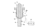
- a die used in the press molding method of the present embodiment includes a punch 2 for extruding a bottom wall 1a of a cup-shaped material (molded material) 1 downward;
- a wrinkle presser 3 that has a cylindrical shape covering the periphery of 2 and presses the inner surface of the material 1 with its outer peripheral surface during the molding process; an annular shape that surrounds the periphery of the wrinkle presser 3;
- An outer peripheral punch 4 formed with a protrusion 4a that pushes the edge surface 1c downward; and a punch 2 and a wrinkle presser 3 that descend while pressing the bottom wall 1a of the raw material 1 downward. Is inserted into a through hole 5a formed inside the die 5 and sandwiched between the punch 2 and the bottom wall 1a of the material 1 is sandwiched and pressed.
- Press molding having a drive mechanism capable of individually and independently controlling the movement of the punch 2, the wrinkle presser 3, the outer peripheral punch 4 and the counter punch 6 among the parts of the mold divided into a plurality of parts as described above.
- the material 1 is formed into a predetermined size and shape.
- FIG. 2 is a functional block diagram of a press molding apparatus that drives each part of the mold.
- the controller 10 reads the calculation program stored in the storage unit 11 and controls the drive mechanism of the press molding apparatus.
- This calculation program is a control program for controlling the moving speed and the like of each part of the mold based on the detection result of the sensor 7, and details will be described later.
- a CPU MPU or the like can be used.
- the press forming apparatus of the present embodiment includes a punch driving unit 21, a wrinkle press driving unit 22, an outer peripheral punch driving unit 23, and a counter punch driving unit 24 as the driving mechanism.
- the punch drive unit 21 drives the punch 2 based on the drive control signal output from the controller 10.
- the wrinkle presser drive unit 22 drives the wrinkle presser 3 based on the drive control signal output from the controller 10.
- the outer periphery punch drive unit 23 drives the outer periphery punch 4 based on the drive control signal output from the controller 10.
- the counter punch drive unit 24 drives the counter punch 6 based on the drive control signal output from the controller 10.
- Each of the drive control signals described above includes a speed change signal, a stop signal, and the like.
- the movement start and movement stop of the punch 2, the wrinkle presser 3, the outer peripheral punch 4, and the counter punch 6 are individually controlled. Similarly, the movement speed and movement stop of the punch 2, the wrinkle presser 3, the outer peripheral punch 4, and the counter punch 6 are individually changed based on the speed change signal output from the controller 10.
- the sensor 7 of the present embodiment is embedded in a portion of the mold that is considered to be filled with the material 1 as the molding process proceeds.
- the part corresponds to, for example, a position corresponding to a part parallel to the moving direction of the outer peripheral punch 4 as shown in FIG. 1B or a part near the inclined surface formed at the tip of the wrinkle presser 3. It is disposed at a position (not shown), a position corresponding to a protrusion 1A described later, or the like. Therefore, the position and number of the sensors 7 may be appropriately changed according to the shape of the mold for press molding, the divided configuration, and the like.
- a drawing method (press molding method) using the mold having the above-described configuration and a press molding apparatus will be described below with reference to FIGS.
- a cup-shaped material 1 (intermediate material) is inserted from a gap provided between the punch 2 and the wrinkle presser 3 and the outer peripheral punch 4 at the standby position and the die 5, and the center axis and the die are inserted.
- the cup-shaped raw material 1 is placed inside the die 5 so that the center axis of the molding surface in 5 substantially matches.
- the cup shape is a bottomed cylindrical shape.
- the punch 2, the wrinkle presser 3 and the outer peripheral punch 4 are lowered as a unit toward the material 1 installed inside the die 5.
- the wrinkle presser 3 and the punch 2 press the bottom wall portion 1a of the cup-shaped material 1 between the die 5 from the upper and lower surfaces, and the outer peripheral punch 4 is the upper edge of the cup-shaped material 1 Stops in contact with the surface 1c.
- the punch 2, the wrinkle presser 3 and the outer peripheral punch 4 move, and at the same time, the counter punch 6 rises along the through-hole 5 a processed in the cylindrical die 5, and the cup-shaped material 1 Stop touching the bottom.
- the cup-shaped material 1 is pressed so as to be sandwiched between the wrinkle presser 3 and the die 5 and between the punch 2 and the counter punch 6 as shown in FIG. 1B. And fixed inside the die 5.
- the outer peripheral punch 4 is also lowered, and the upper edge surface 1c of the cup-shaped material 1 is pressed by the protrusions 4a to promote the inflow of the material 1 into the die 5, for example in FIG. Breaking of the material 1 at the tip corner of the punch 2 as shown is prevented.
- the pressing of the upper edge surface 1c of the material 1 with the outer peripheral punch 4 to cause the material 1 to flow into the die 5 is effective in preventing the material 1 from being broken during press molding and improving the forming limit.
- the load acting on the outer peripheral punch 4 and the wrinkle presser 3 is greatly increased and used. As a result, the load limit of the press forming apparatus (the drive force limit of the outer peripheral punch drive unit 23 and the wrinkle press drive unit 22) may be exceeded, and as a result, it may become impossible to continue press forming.
- the reason why the molding load greatly increases during the press molding depending on the operating conditions of the outer peripheral punch 4 is considered as follows.
- a gap is provided between the material 1 and the die 5 before press molding and between the material 1 and the wrinkle presser 3. If there is no gap between the material 1 and the die 5, the material 1 and the die 5 are engaged with each other before the material 1 is installed at a predetermined position in the die 5. Can no longer be moved, making it difficult to put the material 1 to the predetermined position.
- the material 1 when the material 1 is forcibly moved in a state where there is not a sufficient gap between the surface of the material 1 and the molding surface in the mold, the material 1 is tilted with respect to a normal posture. There is a case where only the end portion comes into contact with the mold. If the material 1 is forcibly moved in the mold in such a state, a problem of damaging the material 1 or the mold occurs. Furthermore, the force acting locally on the mold may become excessive, and the mold may be damaged such as a crack. In order to avoid such a problem, the material 1 to be press-molded is designed to have a size and a shape that can ensure a certain gap with the molding surface of the mold.
- the material of the material 1 is caused to flow into the die 5 by lowering the outer peripheral punch 4 and pressing the upper edge surface 1 c of the material 1.
- breakage at the corner of the tip of the punch 2 can be prevented.
- the material 1 is excessively pushed into the die 5 due to the lowering of the outer peripheral punch 4, after the material fills the gap between the molding surface of the mold and the surface of the material 1. Further, the pressing by the outer peripheral punch 4 is continuously performed. As a result, the material is further forcibly fed to the portion filled with the material, and the molding load applied by the outer peripheral punch drive unit 23 and the wrinkle press drive unit 22 is greatly increased.
- the overload state of the material 1 during press molding is detected. Between the material 1 and the mold so that there is no gap between the press-molded product and the mold without pushing the material further into the part and increasing the molding load more than necessary. It is important to manage the gap and keep it appropriate.
- the lowering speed of the outer peripheral punch 4 is made slower than the lowering speed of the punch 2. Then, although the molding load did not exceed the load capacity of the press molding apparatus, the molding was completed while leaving a gap between the material 1 and the mold, resulting in a defective shape in the press molded product. . From the above results, in order to complete press molding without causing an unfilled portion between the material 1 and the mold and without excessive molding load, the gap filling condition of the material inside the mold is determined.
- a sensor 7 for detecting the deformation amount of the mold is incorporated in the mold. It is. Then, the deformation of the mold accompanying the filling of the material inside the mold during press molding was detected using the signal output from the sensor 7 to detect the overload condition of the mold. Furthermore, a method of controlling the lowering speed of the die such as the punch 2 to an appropriate value in accordance with the overload condition is adopted. According to this method, an unfilled portion of the material 1 does not occur in the mold, and the molding load becomes excessive and exceeds the load capacity of the press molding apparatus. The molding can be completed without stopping.
- the flowchart in FIG. 5 shows processing performed by the controller 10 in accordance with the arithmetic program stored in the storage unit 11 shown in FIG.
- the controller 10 first reads a sensor output determination value ⁇ J set in advance for the output signal from the sensor 7 from the storage unit 11 (step S101). Thereafter, the controller 10 sequentially reads the sensor output ⁇ j from each sensor 7 during press molding (step S102).
- step S102 the stroke S PS when the target specified portion of the pre-control has moved whether the host vehicle has reached the predetermined final stroke S PSE
- the controller 10 determines (Step S103). If it is determined that the stroke S PS has reached the predetermined final stroke S PSE (step S103, Yes), the control is terminated and it is determined that the stroke S PS has not reached (step S103, No). In step S104, the process proceeds to step S104.
- step S104 If the sensor output epsilon j from the sensor 7 is the sensor output when the determination value does not exceed the epsilon J controller 10 determines (step S104, No), the mold while sequentially reads the sensor output epsilon j from each sensor 7 The press forming is continued without changing the descent speed, and the process returns to step S102.
- the lowering speed V PS of the part that is determined as a control target in advance is an arbitrary value smaller than 1 that is separately determined with respect to the value V PS0 that is set at the initial stage of molding. Decelerate to a value multiplied by the value ⁇ (step S105).
- step S106 press molding is continuously performed while sequentially reading the sensor outputs ⁇ j from the sensors 7 (step S106). Furthermore, it is determined whether or not the stroke S PS of the part that is determined as a control target in advance reaches the predetermined final stroke S PSE among the parts of the mold divided into a plurality of parts (Step S107). If so (step S107, Yes), the control ends there.
- the predetermined sensor is set before the stroke S PS of the part determined as the object of control reaches the predetermined final stroke SPSE (No in step S107).
- step S108, Yes the molded modified again to a value V PS0 of the descending speed V PS portion which defines a pre-control of the target was set in the molding initial.
- the stroke S PS portion which defines a pre-control of the target among a plurality of portions in the divided mold each portion reaches a predetermined final stroke S PSE, repeat the above operation (step S110, No) .
- the output value from the sensor 7 exceeds the determination value by comparing the output value from the sensor 7 with a determination value corresponding to a predetermined overload state during molding, the output value is divided into a plurality. Further, the moving speed of one or a plurality of parts of each part of the mold is corrected so that the output value from the sensor 7 does not exceed a predetermined determination value. Along with the correction of the moving speed, the material flow from the thickened portion of the material 1 where the overload state is detected to another portion that is not in the overload state occurs. As the material flow proceeds, the output value from the sensor 7 gradually decreases. When the output value from the sensor 7 falls below a predetermined determination value, the moving speed of each part of the mold is adjusted again so that the output value from the sensor 7 increases.
- the relationship between the filling condition of the material in the mold and the output signal from the sensor 7 may be obtained in advance by experiment or the like for each mold shape to be used.
- the determination value to be compared with the output signal from the sensor 7 in order to determine whether or not to correct the moving speed of the mold during molding is, for example, without causing problems such as overload in normal production. It is conceivable that the output value of the sensor 7 in the molding process when the press molding is normally completed is sequentially accumulated, and the maximum value of the accumulated data is used as the determination value. In addition, a separate press molding experiment is performed, and an overload value obtained based on the relationship between the molding state of the press molded product inside the mold and the output value of the sensor 7 can be used as the determination value. Separately, numerical calculation such as the finite element method is performed, and a calculated value corresponding to the output of the sensor 7 estimated to be obtained when the material 1 is filled in the mold is used as the determination value. You can also.
- a preliminary process including a calculation process, an actual measurement process, and a correction process shown below is performed in advance, and a predicted correspondence relationship after correction obtained in the preliminary process (described later) Accordingly, actual press molding may be performed.
- the calculation step a predicted correspondence relationship between at least one of the driving force, the driving speed, and the driving timing to be applied to each part of the divided mold, and the pressing force without an overload state, Obtained by numerical calculations such as the finite element method.
- the respective parts of the mold are independently driven to press-mold the material 1, while the material 1 being molded becomes the respective parts of the mold.
- a measured correspondence relationship between the pressing force obtained by actually measuring the applied pressing force by the sensor 7 and at least one of the driving force, the driving speed, and the driving timing is obtained.
- the correction step a difference between the predicted correspondence relationship obtained in the calculation step and the actual measurement correspondence relationship obtained in the actual measurement step is obtained, and the prediction correspondence after correction is corrected by correcting the prediction correspondence relationship. Get correspondence.
- FIG. 6A in the process of lowering the outer peripheral punch 4 and the punch 2 and proceeding press forming, the outer peripheral surface of the protrusion 1A formed on the bottom wall 1a of the cup-shaped material 1 and the die 5
- the material 1 is filled inside the mold, and the mold (die 5) in this portion is deformed.
- a signal is output from a sensor 7 provided at a position corresponding to the vertical wall portion 1b in the die 5. If this signal exceeds a predetermined determination value, punching is performed based on the signal.
- the calculation program for controlling the operation of the second mold, etc. the movement speed of each part of the mold is corrected so as to reduce the deformation of the mold near the sensor 7 and the molding is continued.
- the descending speed V p of the punch 2 remains constant and relatively slower than the descending speed V 0 which outer peripheral punch 4 descent velocity V p.
- the load applied to the outer peripheral punch 4 by accelerating the material inflow of the material 1 from the vertical wall 1b to the protrusion 1A due to the pulling of the punch 2 and alleviating the excessive material filling in the vertical wall 1b.
- the molding load is prevented from being stopped due to the molding load exceeding the load capacity of the press molding apparatus, while suppressing an increase in the molding load.
- the load from the sensor 7 accompanying the deformation of the mold is increased.
- the relative descending speed between the outer peripheral punch 4 and the punch 2 is appropriately changed. As a result, it is possible to prevent the occurrence of an unfilled portion in the vertical wall portion 1b, and without causing a situation in which an overload condition occurs and the molding load exceeds the load capacity of the press molding apparatus. Can be obtained.
- the relative lowering speed between the outer peripheral punch 4 and the punch 2 is appropriately changed.
- control element is not limited to the lowering speed, and the driving force and driving applied to each part of the mold At least one of speed and driving timing can be used. That is, a relative difference may be provided between the driving force of the outer peripheral punch 4 and the driving force of the punch 2, or a relative difference may be provided between the driving timing of the outer peripheral punch 4 and the driving timing of the punch 2. . Furthermore, a relative difference may be provided between the outer peripheral punch 4 and the punch 2 in all combinations of the three elements of driving force, driving speed, and driving timing.
- the punch 2, the wrinkle presser 3, the outer peripheral punch 4, and the counter punch 6, are independently driven to press-mold the material 1, A first step of obtaining a pressing force applied to the die 5 of the mold by the material 1 during the press molding by the sensor 7; and pressing of the material 1 detected based on the pressing force when approaching an overload state. Secondly, at least one of the applied driving force, the driving speed, and the driving timing is adjusted for each of the punch 2 and the outer peripheral punch 4 of the die so that the portion flows to the other press-worked portion of the material 1. And comprising the steps of:
- the pressing force is obtained on the basis of the deformation amount (strain amount) of the die 5 of the mold that is generated with the flow of the material 1 during press molding.
- the said press molding is drawing forming which shape
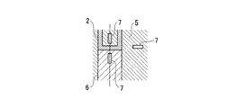
- the pressing force may be obtained at a plurality of locations in the circumferential direction centering on the axis. That is, in the example of the figure, at the height positions of the AA cross section and the BB cross section of FIG. 1A in the die 5, four sensors 7 are arranged in the die 5 at equal angular intervals of 45 ° around the axis. Is arranged.
- the pressing force is detected by a sensor 7 provided in the punch 2 and a sensor 7 provided in the counter punch 6 in addition to the sensor 7 provided in the die 5. .
- a position of the detection part of the sensor 7 it is arrange
- the material filling in the vertical wall portion 1b and the protruding portion 1A may not necessarily occur uniformly.
- the material filling proceeds sequentially from the upper edge portion of the vertical wall portion 1b toward the bottom wall portion 1a.
- the outer peripheral punch 4 continues to push down the partially filled vertical wall portion 1b and the molding load increases, the molding load is increased before the entire vertical wall portion 1b is filled with the material. May become excessive, and press forming may be completed in a state where an unfilled portion remains in the mold.
- each embodiment of this invention was described based on drawing, this invention is not limited only to the content of an indication of these embodiment.
- the molding method targeted by each embodiment is not necessarily limited to a method using a cup-shaped intermediate material as shown in FIGS. 1A to 1C, and for example, a circle as shown in FIGS. 11A to 11C. It can also be applied to a method of forming a final product from a plate-shaped material in one step.
- the mold divided into a plurality of parts whose relative speed ratio is controlled is not necessarily limited to only the above-described punch side, and a plurality of parts It is also possible to apply to the relative speed control between a plurality of dies and punches by applying to a die side (not shown) divided into two. Furthermore, both the dice and the punch may be divided into a plurality of parts (not shown), and relative speed control may be performed in each part.
- the shape of the material 1 and the mold shape shown in each embodiment are examples for explaining the present invention, and other shapes may be adopted.
- the strain sensor is used as means for detecting the pressing force applied by the material to be molded to each part of the mold, but it is also conceivable to use ultrasonic waves or magnetic changes as other means. .
- Example 1 A cup-shaped intermediate material having an outer diameter of 48 mm, a plate thickness of 3 mm, and a height of 40 mm, drawn from a disk-shaped carbon steel material having an outer diameter of 100 mm and a plate thickness of 3 mm, is shown in FIGS. 1A to 1C.
- a cylindrical protrusion 1A having an outer diameter of 23 mm and a thickness of 3 mm was formed on the bottom wall 1a by a molding method.
- the sensor 7 was disposed in each position shown in FIGS. 1A to 1C in the mold, and the amount of strain accompanying the deformation of the mold was measured.
- press molding was performed for comparison. That is, after the press forming was advanced to the state of FIG. 1B, the press forming was performed by setting the descending speed of the outer peripheral punch 4 to a constant value that is 1.4 times the descending speed of the punch 2. As a result, an overload state occurred in the vertical wall portion 1b during the press molding, and the molding was interrupted because the load exceeded the allowable limit of the press molding apparatus.
- press molding was performed by applying the first embodiment. That is, after the molding is advanced to the state of FIG. 1B, the lowering speed of the outer peripheral punch 4 is set to 1.4 times the lowering speed of the punch 2, and the mold is used by using each sensor 7 arranged in the mold. Molding was started while measuring the amount of strain associated with the deformation. Then, during the press molding, the distortion signal measured by the sensor 7 arranged at the position corresponding to the vertical wall portion 1b has reached a predetermined determination value. Reduced speed.
- the lowering speed of the outer peripheral punch 4 was slowed from 1.4 times to 1.0 times the initial lowering speed of the punch 2.
- the lowering speed of the outer punch 4 is set to the initial lowering of the punch 2 according to an instruction from the controller 10. Increased to 1.4 times the speed.
- Example 2 First, simple press molding was performed for comparison. That is, using a disk-shaped stainless steel material having an outer diameter of 150 mm and a plate thickness of 4 mm, an outer surface of the cup-shaped member having an outer diameter of 80 mm and a thickness of 4 mm is formed on the bottom surface by the press molding method shown in FIGS. 11A to 11C. A cylindrical projection 1A having a diameter of 35 mm and a thickness of 4 mm was formed. At that time, as shown in FIG. 11A, three sensors 7 are arranged in the mold for each of the vertical wall portion 1b and the protrusion portion 1A, and the amount of strain distribution caused by the deformation of the mold. was measured finely. After the press molding was advanced to the state of FIG. 11B, the lowering speed of the outer peripheral punch 4 was fixed to 1.2 times the lowering speed of the punch 2 to perform the molding. As a result, the press molding was interrupted because the load exceeded the allowable limit of the press molding apparatus during the press molding.
- the lowering speed of the outer peripheral punch 4 is set to 1.2 times the lowering speed of the punch 2, Then, press molding was started while measuring the amount of strain accompanying the deformation of the mold using each sensor 7 arranged in the mold. Then, during the press molding, the strain signal measured by the sensor 7 disposed on the vertical wall portion 1b reached a predetermined determination value, so that the lowering speed of the outer peripheral punch 4 was slowed by an instruction from the controller 10.
- the judgment value an output value at the time of overload obtained from the relationship between the molding state of the press-molded product inside the mold and the output value of the sensor, which was separately collected in a press molding experiment, was used.
- the lowering speed of the outer peripheral punch 4 was decreased from 1.2 times to 0.9 times the initial lowering speed of the punch 2.
- the lowering speed of the outer punch 4 is set to the initial lowering speed of the punch 2 according to an instruction from the controller 10. It was increased to 1.2 times.
- the load applied to the mold does not exceed the load limit of the press molding apparatus and cannot be molded, and a product free from shape defects due to unfilled material in the mold is stabilized from the material.
Landscapes
- Engineering & Computer Science (AREA)
- Mechanical Engineering (AREA)
- Shaping Metal By Deep-Drawing, Or The Like (AREA)
- Control Of Presses (AREA)
Abstract
Description
本願は、2014年05月19日に、日本国に出願された特願2014-103735号に基づき優先権を主張し、その内容をここに援用する。
例えば、非特許文献1には、底部から開口部まで内径が一定である円筒状の容器や、底部から開口部に至る途中で内径が変化する段部を有する有段円筒状の製品を成形する方法が記載されている。すなわち、第一工程で円盤状の素材からカップ状に成形した中間素材を第二工程で再度絞り加工しており、このような再絞り加工方法によってカップ状の中間素材をさらに絞り成形する方法が広く一般的に行われている。
さらには、特許文献2には、カップ状の中間素材より成形するのではなく、板状の素材から一工程で最終製品まで成形する方法が開示されている。
特許文献3~5には、プレス成形中の金型内の荷重分布や歪み量を測定する方法及び装置が開示されている。しかしながら、一般的に用いられる成形方法では、分割された金型の各部分ごとに、整形開始前に予め設定した一定速度で移動させながら成形を行うのみであり、素材寸法やプレス成形の進行状況に応じて移動速度を成形中に修正することは行っていない。
逆に、第一のパンチ及び第二のパンチ双方の荷重が絞り加工装置の成形荷重限界の範囲内であるものの、金型内に材料の未充満部が残ってしまい、その結果として製品の形状不良が起きる虞も有る。
(1)本発明の一態様に係るプレス成形方法は、複数に分割された金型の各部それぞれを独立に駆動して被成形素材をプレス成形しながら、プレス成形中の前記被成形素材が前記金型の前記各部に付与する押圧力を求める第1の工程と;過負荷状態に近づいたことが前記押圧力に基づいて検出された前記被成形素材の加工部分を、前記被成形素材の他の加工部分に流動させるように、付与する駆動力、駆動速度、駆動タイミングのうちの少なくとも一つを、前記金型の前記各部毎に調整する第2の工程と;を備える。
上記(3)の場合、プレス成形中における被成形素材の流動状態に基づいて瞬時に判断して、金型の各部の動作を制御することができる。
上記(5)の場合、軸線の延在方向に沿った複数箇所で押圧力を求めるので、被成形素材の成形過程をより細かく把握することが可能となる。さらには、軸線方向に沿って得た押圧力のデータを、プレス成形をシミュレーションする数値計算モデルに取り込んで計算精度を上げるといった応用も可能となる。
上記(6)の場合、軸線の延在方向と周方向との双方で押圧力を求めるので、被成形素材の成形過程を立体的に把握することが可能となる。
上記(11)の場合、軸線の延在方向に沿った複数箇所で押圧力を求めることができるので、被成形素材の成形過程をより細かく把握することが可能となる。さらには、軸線方向に沿って得た押圧力のデータを、プレス成形をシミュレーションする数値計算モデルに取り込んで計算精度を上げるといった応用も可能となる。
上記(12)の場合、軸線の延在方向と周方向との双方で押圧力を求めるので、被成形素材の成形過程を立体的に把握することが可能となる。
上記(14)の場合、歪みセンサーの感度範囲内で精度良く測定することが可能となる。
各実施形態では、複数の部分に分割された金型の各部を独立して作動させることが可能なプレス成形装置を用いた絞り成形方法において、金型の変形を測定するセンサーが内部に挿入された金型を用い、センサーにより測定された金型の変形量に対応した出力信号を元に成形中の金型の過負荷状況を検知した上で、その過負荷状況に応じて複数の部分に分割された金型各部の移動速度比等を適切に制御している。
そして、このような制御を行うことにより、プレス成形装置の限界を超えるような過大な荷重により成形の継続が不可能となることや、金型内での材料の未充満に伴う製品の形状不良を防止する。その結果、板状の素材やカップ状の中間素材等を金型内部に充満させて、素材各部を所定の板厚および形状とした製品を得ることが可能となっている。
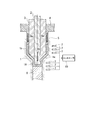
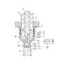
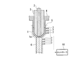
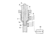
図1A~図1Cに示すように、本実施形態のプレス成形方法に使用する金型は、カップ状の素材(被成形素材)1の底壁部1aを下方に向かって押し出すパンチ2と;パンチ2の周囲を覆う筒形状を有し、成形過程中にその外周面で素材1の内面を押圧するしわ押え3と;しわ押え3の周囲を囲むような環状であり、下面に素材1の上縁面1cを下方に向かって押し込む突起部4aが形成された外周パンチ4と;素材1の底壁部1aを下方に向かって押圧しながら降下するパンチ2及びしわ押え3との間で素材1を挟み込んで、所定の外形寸法に仕上げる円環形状のダイ5と;ダイ5の内部に形成された貫通孔5aに挿入されてパンチ2との間で素材1の底壁部1aを挟み込んで押圧するカウンターパンチ6と;を備えている。
したがって、プレス成形を行う金型の形状や分割構成等に応じて、センサー7の配置される位置や個数は適宜変更してもよい。
まず、パンチ駆動部21、しわ押え駆動部22及び外周パンチ駆動部23を駆動することで、パンチ2、しわ押え3、外周パンチ4を所定高さの待機位置まで上昇させる。
プレス成形前の素材1とダイ5との間、及び素材1としわ押え3との間には、一般に、隙間が設けられている。もし、素材1とダイ5との間に隙間を設けていないと、素材1がダイ5内の所定位置に設置される前に、素材1とダイ5とが噛み合って嵌合状態となり、素材1をそれ以上移動させることができなくなり、素材1を前記所定位置まで入れることが難しくなる。
さらには、金型の内部におけるパンチ2の先端部周辺位置への材料供給が不足して、成形品に、図3に示したようなパンチ2の角部における破断を生じる場合がある。従って、上述の成形荷重上昇によるプレス成形不能を防止しつつ、金型内に未充満部を残さないプレス成形品を成形するためには、プレス成形中の素材1の、過負荷状態が検出された部分に対してさらに材料を押し込んで必要以上に成形荷重を増加させてしまうことなく、かつプレス成形品と金型との間に隙間が残らないように、素材1と金型との間の隙間を管理して適正に保つことが重要となる。
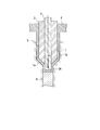
すなわち、まず図1Aに示すように、ダイ5内にカップ状の素材1を設置した後、パンチ2及びしわ押え3及び外周パンチ4が一体となって降下するようにプレス成形装置を動作させた。そして、図1Bに示すように、しわ押え3及びパンチ2を素材1の底面に、外周パンチ4をカップ状の素材1の上縁面1cに接触させて停止することにより、素材1をダイ5の内部に固定した。
続いて、パンチ2及びカウンターパンチ6を降下させて素材1の底壁部1aにおける筒状の突起部1Aの成形を開始すると、プレス成形初期の段階では、縦壁部1bの外周面とダイ5との間に隙間がある状態のまま、プレス成形が進む。
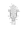
その後、図4Bに示すように、突起部1Aのプレス成形の進行と共に、縦壁部1bでは素材1の上縁側から底壁部1a側に向かって、順次隙間が縮小していく。そして、最終的には、図4Cに示すように素材1が金型内に充満して成形が完了する様子が確認された。
例えば、外周パンチ4の降下速度をパンチ2の降下速度に対して速くしていくと、パンチ2による突起部1Aの伸び量に対して、外周パンチ4による縦壁部1bの押し込み量が過大となった。その結果、縦壁部1bの素材1が金型内に充満した後も外周パンチ4による縦壁部1bの押し込みが継続して行われることとなり、縦壁部1bの充満部分に対してさらに強制的に材料を押し込もうとする過負荷状態となった。その結果、外周パンチ4の成形荷重がプレス成形装置の荷重容量を超えてしまい、突起部1Aに未充満部分を残したまま、プレス成形が中断した。
以上の結果から、素材1と金型との間で未充満部分を生じず、しかも成形荷重が過大となることなくプレス成形を完了させるためには、金型内部での素材の隙間充満状況を管理して、以下を防止することが重要であることがわかった。すなわち、縦壁部1b及び突起部1Aの各部に関し、プレス成形の途中で一方に隙間が残ったまま他方の隙間に成形品が充満した後も、外周パンチ4によるダイ5の内部への材料の押し込みが継続されてしまうと、充満部が過負荷状態となって成形荷重の増加が大きくなり、プレス成形装置の荷重容量を超過して成形を継続することができなくなるので、これを防止することが重要である。
そして、ストロークSPSが所定の最終ストロークSPSEに到達したと判定された場合(ステップS103,Yes)には、そこで制御を終了し、到達していないと判定された場合(ステップS103,No)には、ステップS104に進む。
センサー7からのセンサー出力εjが前記センサー出力判定値εJを超えていないとコントローラ10が判定した場合(ステップS104,No)は、各センサー7からのセンサー出力εjを逐次読み込みながら金型の降下速度は変更せずにプレス成形を継続して行い、処理をステップS102に戻す。
さらに、複数の部分に分割された金型の各部のうち、予め制御の対象と定めた部分のストロークSPSが所定の最終ストロークSPSEに到達したか否かを判定し(ステップS107)、到達した場合(ステップS107,Yes)には、そこで制御を終了する。
移動速度の修正に伴って、過負荷状態が検出された素材1の増肉部分から、過負荷状態でない他の部分への材料流動が生じる。そして、この材料流動が進むことで、センサー7からの出力値が徐々に低下する。センサー7からの出力値が予め定めた判定値を下回った場合には、再度、センサー7からの出力値が増加するように金型の各部の移動速度を調整する。
また、別途、有限要素法等の数値計算を行って、金型内に素材1の材料が充満した場合に得られると推定されるセンサー7の出力に相当する計算値を、前記判定値として用いることもできる。
前記計算工程では、分割された金型の各部に対して付与する、駆動力及び駆動速度及び駆動タイミングのうちの少なくとも一つと、過負荷状態を伴わない押圧力との間における予測対応関係を、有限要素法等の数値計算で求める。
前記補正工程では、前記計算工程で得られた前記予測対応関係と、前記実測工程で得られた前記実測対応関係との差異を求め、前記予測対応関係を補正することで、前記補正後の予測対応関係を得る。
図6Aに示すように、外周パンチ4及びパンチ2を降下させてプレス成形を進めていく過程において、カップ状の素材1の底壁部1aに形成される突起部1Aの外周面とダイ5の内周面との間に隙間が残った状態で、縦壁部1bでは金型内部に素材1が充満して、この部分の金型(ダイ5)に変形が生じる。この変形に伴い、ダイ5内の縦壁部1bに対応した位置に設けられたセンサー7から信号が出されるが、この信号が、予め定めた判定値を超えた場合、その信号を元にパンチ2等の金型の動作を制御する演算プログラムにより、センサー7付近の金型の変形を低減させるように金型の各部の移動速度を修正して成形を継続させる。
このようなセンサー7からの出力信号に基づく金型動作の制御を繰り返すことにより、成形荷重がプレス成形装置の荷重容量を超過することによる成形停止を生じさせることなく、図6Bに示すように金型内部に素材1の材料を充満させてプレス成形が完了する。
なお、上記実施形態では、外周パンチ4及びパンチ2間の相対的な降下速度を適宜変更するものとしたが、制御要素は降下速度のみに限らず、金型の各部に付与する駆動力、駆動速度、駆動タイミングのうちの少なくとも一つを用いることが可能である。すなわち、外周パンチ4の駆動力とパンチ2の駆動力との間に相対差を設けても良いし、外周パンチ4の駆動タイミングとパンチ2の駆動タイミングとの間に相対差を設けても良い。さらには、駆動力、駆動速度、駆動タイミングの三要素の組み合わせ全てにおいて、外周パンチ4及びパンチ2間で相対差を設けてもよい。
本実施形態に係るプレス成形方法は、複数に分割された金型である、パンチ2、しわ押え3、外周パンチ4、カウンターパンチ6のそれぞれを独立に駆動して素材1をプレス成形しながら、プレス成形中の素材1が金型のダイ5に付与する押圧力をセンサー7で求める第1の工程と;過負荷状態に近づいたことが前記押圧力に基づいて検出された素材1のプレス加工部分を、素材1の他のプレス加工部分に流動させるように、付与する駆動力、駆動速度、駆動タイミングのうちの少なくとも一つを、金型のパンチ2及び外周パンチ4毎に調整する第2の工程と;を備える。
前記第2の工程で、前記押圧力が、所定の閾値(判定値)を超えたか否かにより、前記過負荷状態に近付いたか否かを判定している。
また、前記プレス成形は、素材1を、軸線を有する円筒状部材に成形する絞り成形である。なお、例えば図8A及び図8Bに示すように、前記押圧力を、前記軸線を中心とする周方向の複数箇所で求めるようにしてもよい。すなわち、同図の例では、ダイ5における図1AのA-A断面とB-B断面のそれぞれの高さ位置において、軸線回りに45°の等角度間隔で4個ずつセンサー7がダイ5内に配置されている。
以下に、本発明の第2実施形態を説明するが、上記第1実施形態との相違点を主に説明し、その他については上記第1実施形態と同様であるとして重複説明を省略する。
本実施形態では、図10A及び図10Bに示すように、縦壁部1b及び突起部1Aのそれぞれに対応した位置に組み込まれる各センサー7が、それぞれ軸線方向に沿って複数個ずつ配置されている。
例えば、各実施形態が対象とする成形方法は、必ずしも、図1A~図1Cに示したようなカップ形状の中間素材を用いる工法のみに限定されず、例えば図11A~図11Cに示すような円板状の素材から一工程で最終製品を成形する工法にも適用できる。
各実施形態で示した素材1の形状や金型形状は、本発明の説明に際しての例示であり、その他の形状を採用してもよい。
なお、金型の各部に対して被成形素材が付与する押圧力を検知する手段として上記実施形態では歪みセンサーを用いたが、その他の手段として、超音波や磁気変化を利用することも考えられる。
外径100mmで板厚3mmの円板状の炭素鋼素材から絞り成形した、外径48mm、板厚3mm、高さ40mmを有するカップ形状の中間素材を用いて、図1A~図1Cに示した成形方法により、底壁部1aに外径23mmで厚さ3mmの筒状の突起部1Aを成形した。その際、金型内には図1A~図1Cに示す各位置にセンサー7を配置して、金型の変形に伴う歪み量を測定した。
次に、上記第1実施形態を適用してプレス成形を行った。すなわち、図1Bの状態まで成形を進めた後に、外周パンチ4の降下速度をパンチ2の降下速度の1.4倍に設定した上で、金型内に配置した各センサー7を用いて金型の変形に伴う歪み量を測定しながら成形を開始した。そして、プレス成形の途中で、縦壁部1bに対応した位置に配置されたセンサー7で測定された歪み信号が、予め定めた判定値に達したため、コントローラ10からの指示で外周パンチ4の降下速度を遅くした。
その後、センサー7からの歪み信号の値が徐々に低下し、前記判定値の0.9倍となった時点で、コントローラ10からの指示により外周パンチ4の降下速度を、初期におけるパンチ2の降下速度の1.4倍まで増加させた。その結果、プレス成形荷重が成形装置の許容限界を超えることなく、プレス成形を完了させることができた。
まず、比較のために単純なプレス成形を行った。すなわち、外径150mmで板厚4mmの円板状のステンレス鋼素材を用いて、図11A~図11Cに示したプレス成形方法により、外径80mmで厚さ4mmのカップ状部材の底面に、外径35mmで厚さ4mmの筒状の突起部1Aを成形した。その際、金型内には、図11Aに示したように、縦壁部1b及び突起部1Aのそれぞれに対して、3個ずつセンサー7を配置して、金型の変形に伴う歪み量分布を細かく測定した。図11Bの状態までプレス成形を進めた後、外周パンチ4の降下速度を、パンチ2の降下速度の1.2倍に固定して成形を行った。その結果、プレス成形の途中で荷重がプレス成形装置の許容限界を超えたため、プレス成形が中断した。
その後、センサー7からの歪み信号の値が徐々に低下し、前記判定値の0.8倍となった時点で、コントローラ10からの指示により外周パンチ4の降下速度を初期におけるパンチ2の降下速度の1.2倍にまで増加させた。その結果、プレス成形荷重がプレス成形装置の許容限界を超えることなく、プレス成形を完了させることができた。
2 パンチ
3 しわ押え
4 外周パンチ
5 ダイ
6 カウンターパンチ
7 歪みセンサー、センサー
10 コントローラ
11 記憶部
21 パンチ駆動部
22 しわ押え駆動部
23 外周パンチ駆動部
24 カウンターパンチ駆動部
Claims (14)
- 複数に分割された金型の各部それぞれを独立に駆動して被成形素材をプレス成形しながら、プレス成形中の前記被成形素材が前記金型の前記各部に付与する押圧力を求める第1の工程と;
過負荷状態に近づいたことが前記押圧力に基づいて検出された前記被成形素材の加工部分を、前記被成形素材の他の加工部分に流動させるように、付与する駆動力、駆動速度、駆動タイミングのうちの少なくとも一つを、前記金型の前記各部毎に調整する第2の工程と;
を備えることを特徴とするプレス成形方法。 - 前記第1の工程で、前記押圧力を、前記プレス成形中の前記被成形素材の流動に伴って発生する前記金型の変形量に基づいて求めることを特徴とする請求項1に記載のプレス成形方法。
- 前記第2の工程で、前記押圧力が、所定の閾値を超えたか否かにより、前記過負荷状態に近付いたか否かを判定することを特徴とする請求項1又は2に記載のプレス成形方法。
- 前記プレス成形が、前記被成形素材を、軸線を有する円筒状部材に成形する絞り成形であり;
前記押圧力を、前記軸線を中心とする周方向の複数箇所で求める;
ことを特徴とする請求項1~3の何れか一項に記載のプレス成形方法。 - 前記プレス成形が、前記被成形素材を、軸線を有する円筒状部材に成形する絞り成形であり;
前記押圧力を、前記軸線の延在方向に沿った複数箇所で求める;
ことを特徴とする請求項1~3の何れか一項に記載のプレス成形方法。 - さらに、前記押圧力を、前記軸線を中心とする周方向の複数箇所で求める
ことを特徴とする請求項5に記載のプレス成形方法。 - 前記金型が、ダイ及びパンチを含み;
前記押圧力を、前記ダイ及び前記パンチの少なくとも一方に設けられた歪みセンサーにより求める;
ことを特徴とする請求項1~6の何れか一項に記載のプレス成形方法。 - 前記第1の工程の前に、
前記駆動力及び前記駆動速度及び前記駆動タイミングのうちの少なくとも一つと、前記過負荷状態を伴わない前記押圧力との間における予測対応関係を数値計算で求める計算工程と;
前記計算工程で得られた前記予測対応関係に従って、前記金型の前記各部それぞれを独立に駆動して前記被成形素材をプレス成形しながら、成形中の前記被成形素材が前記金型の前記各部に付与する前記押圧力を実測することで、実測された前記押圧力と、前記駆動力及び前記駆動速度及び前記駆動タイミングのうちの少なくとも一つとの間における実測対応関係を求める実測工程と;
前記計算工程で得られた前記予測対応関係と、前記実測工程で得られた前記実測対応関係との差異を求め、前記予測対応関係を補正する補正工程と;
を含む予備工程を行い、
前記予備工程で得られた補正後の前記予測対応関係に従って、前記第1の工程を行う
ことを特徴とする請求項1~7の何れか一項に記載のプレス成形方法。 - 複数に分割され、各部が駆動力を個別に受けて被成形素材をプレス成形する金型であって、
前記プレス成形時に前記被成形素材から前記金型の成形面が受ける押圧力を取得するセンサーが設けられている
ことを特徴とするプレス成形用金型。 - 前記被成形素材を、軸線を有する円筒状部材に成形する絞り成形用であり;
前記センサーが、前記軸線を中心とする周方向の複数箇所に設けられている;
ことを特徴とする請求項9に記載のプレス成形用金型。 - 前記被成形素材を、軸線を有する円筒状部材に成形する絞り成形用であり;
前記センサーが、前記軸線の延在方向に沿った複数箇所に設けられている;
ことを特徴とする請求項9に記載のプレス成形用金型。 - さらに、前記センサーが、前記軸線を中心とする周方向の複数箇所に設けられている
ことを特徴とする請求項11に記載のプレス成形用金型。 - ダイ及びパンチを含み;
前記センサーが、前記ダイ及び前記パンチの少なくとも一方に設けられた歪みセンサーである;
ことを特徴とする請求項9~12の何れか一項に記載のプレス成形用金型。 - 前記歪みセンサーの検出部が、前記歪みセンサーが設けられた前記ダイ及び前記パンチの少なくとも一方の成形面より、5mm以上50mm以下の深さ位置に設けられている
ことを特徴とする請求項13に記載のプレス成形用金型。
Priority Applications (6)
| Application Number | Priority Date | Filing Date | Title |
|---|---|---|---|
| KR1020167031518A KR101949002B1 (ko) | 2014-05-19 | 2015-05-13 | 프레스 성형 방법 및 프레스 성형용 금형 |
| CN201580025771.9A CN106457343B (zh) | 2014-05-19 | 2015-05-13 | 冲压成型方法及冲压成型用模具 |
| US15/311,883 US10376941B2 (en) | 2014-05-19 | 2015-05-13 | Press forming method and tool for press forming |
| JP2016521057A JP6292302B2 (ja) | 2014-05-19 | 2015-05-13 | プレス成形方法及びプレス成形用金型 |
| MX2016015096A MX387865B (es) | 2014-05-19 | 2015-05-13 | Metodo de conformacion en prensa y herramienta para la conformacion en prensa. |
| US16/457,513 US11407019B2 (en) | 2014-05-19 | 2019-06-28 | Press forming method and tool for press forming |
Applications Claiming Priority (2)
| Application Number | Priority Date | Filing Date | Title |
|---|---|---|---|
| JP2014-103735 | 2014-05-19 | ||
| JP2014103735 | 2014-05-19 |
Related Child Applications (2)
| Application Number | Title | Priority Date | Filing Date |
|---|---|---|---|
| US15/311,883 A-371-Of-International US10376941B2 (en) | 2014-05-19 | 2015-05-13 | Press forming method and tool for press forming |
| US16/457,513 Division US11407019B2 (en) | 2014-05-19 | 2019-06-28 | Press forming method and tool for press forming |
Publications (1)
| Publication Number | Publication Date |
|---|---|
| WO2015178267A1 true WO2015178267A1 (ja) | 2015-11-26 |
Family
ID=54553940
Family Applications (1)
| Application Number | Title | Priority Date | Filing Date |
|---|---|---|---|
| PCT/JP2015/063750 Ceased WO2015178267A1 (ja) | 2014-05-19 | 2015-05-13 | プレス成形方法及びプレス成形用金型 |
Country Status (6)
| Country | Link |
|---|---|
| US (2) | US10376941B2 (ja) |
| JP (1) | JP6292302B2 (ja) |
| KR (1) | KR101949002B1 (ja) |
| CN (1) | CN106457343B (ja) |
| MX (1) | MX387865B (ja) |
| WO (1) | WO2015178267A1 (ja) |
Cited By (2)
| Publication number | Priority date | Publication date | Assignee | Title |
|---|---|---|---|---|
| WO2018093422A1 (en) | 2016-11-15 | 2018-05-24 | Pride Engineering, Llc | Tool pack assembly |
| US12076774B2 (en) | 2021-06-25 | 2024-09-03 | Panasonic Intellectual Property Management Co., Ltd. | Press-forming apparatus |
Families Citing this family (12)
| Publication number | Priority date | Publication date | Assignee | Title |
|---|---|---|---|---|
| KR101925829B1 (ko) * | 2016-12-28 | 2018-12-07 | 주식회사전우정밀 | 프레스 금형 장치 및 이를 이용한 성형 방법 |
| US20210260641A1 (en) * | 2017-09-05 | 2021-08-26 | Thyssenkrupp Steel Europe Ag | Method for producing a component and tool therefor |
| CN109647981B (zh) * | 2017-10-10 | 2022-02-08 | 湖北宏力液压科技有限公司 | 一种用于搬运车三角架的多层冲压模具 |
| CN108955756A (zh) * | 2018-04-04 | 2018-12-07 | 安徽安缆模具有限公司 | 一种模具实时监控装置 |
| KR102062228B1 (ko) * | 2018-04-27 | 2020-01-03 | 주식회사전우정밀 | 절곡부위를 증육드로잉하는 드로잉 장치 및 그 작동방법 |
| KR102062229B1 (ko) * | 2018-04-27 | 2020-01-03 | 주식회사전우정밀 | 복수 개의 절곡부위를 증육드로잉하는 복합 증육 드로잉 장치 및 그 작동방법 |
| JP7261984B2 (ja) * | 2019-09-18 | 2023-04-21 | パナソニックIpマネジメント株式会社 | 打ち抜き装置 |
| JP7399050B2 (ja) * | 2019-10-03 | 2023-12-15 | アガトン・アクチエンゲゼルシャフト・マシーネンファブリーク | 基準部品監視システム |
| CN112595099B (zh) * | 2020-12-03 | 2022-06-24 | 攀钢集团重庆钛业有限公司 | 一种降低窑前板框故障影响转窑进料稳定的控制方法 |
| CN113059011B (zh) * | 2021-03-17 | 2022-05-31 | 中北大学 | 一种成形大型锥筒的挤压拉伸复合成形设备 |
| CN113059012B (zh) * | 2021-03-17 | 2022-05-31 | 中北大学 | 一种大高径比锥筒的挤压拉伸复合成形方法 |
| CN114535486B (zh) * | 2022-03-18 | 2024-03-05 | 湘潭大学 | 一种不等厚壳体件板锻造成形方法及模具 |
Citations (6)
| Publication number | Priority date | Publication date | Assignee | Title |
|---|---|---|---|---|
| JPH0557496A (ja) * | 1991-08-31 | 1993-03-09 | Fanuc Ltd | 多段電動式粉末成形機と圧縮成形方法 |
| JPH08174075A (ja) * | 1994-12-28 | 1996-07-09 | Amada Co Ltd | プレスブレーキによる板材折曲げ加工方法及びプレスブレーキ |
| JP2005186142A (ja) * | 2003-12-26 | 2005-07-14 | Toyota Motor Corp | スピンニング加工装置 |
| JP2005205438A (ja) * | 2004-01-21 | 2005-08-04 | Daido Steel Co Ltd | 多段鍛造機の鍛圧測定方法 |
| JP2008132502A (ja) * | 2006-11-27 | 2008-06-12 | Nippon Spindle Mfg Co Ltd | 塑性加工方法 |
| JP2011136368A (ja) * | 2009-12-04 | 2011-07-14 | Hitachi Ltd | サーボプレスの制御装置及び制御方法、並びにこの制御装置を搭載したサーボプレス |
Family Cites Families (19)
| Publication number | Priority date | Publication date | Assignee | Title |
|---|---|---|---|---|
| TW477741B (en) * | 1999-04-28 | 2002-03-01 | Kosmek Kk | Method and device for measuring working force of mechanical press |
| TW553063U (en) * | 1999-08-03 | 2003-09-11 | Kosmek Kk | Device for obtaining calibration data of mechanical press, and load display device for mechanical press |
| US6505492B2 (en) * | 2001-04-11 | 2003-01-14 | Bethlehem Steel Corporation | Method and apparatus for forming deep-drawn articles |
| JP2004322104A (ja) | 2003-04-21 | 2004-11-18 | Aisin Seiki Co Ltd | 絞り成形金型および絞り成形方法 |
| JP2006075884A (ja) * | 2004-09-10 | 2006-03-23 | Nippon Steel Corp | プレス成形加工システム、プレス成形加工方法、及びコンピュータプログラム |
| EP1849590B1 (de) * | 2006-04-29 | 2013-05-15 | Fette GmbH | Presse |
| JP4823886B2 (ja) | 2006-12-18 | 2011-11-24 | 新日本製鐵株式会社 | 薄板のブランキングプレス用金型およびブランク加工方法 |
| JP4943284B2 (ja) | 2006-12-18 | 2012-05-30 | 新日本製鐵株式会社 | 薄板のプレス成形加工装置 |
| WO2008140122A1 (ja) * | 2007-05-09 | 2008-11-20 | Nippon Steel Corporation | 薄板のプレス成形装置及びプレス成形方法 |
| JP2010115702A (ja) | 2008-11-14 | 2010-05-27 | Nippon Steel Corp | プレス成形金型調整用プレス機及び金型調整方法 |
| JP5262872B2 (ja) | 2009-03-13 | 2013-08-14 | アイシン・エィ・ダブリュ株式会社 | 段付カップ状部品の成形装置及び成形方法 |
| JP5528984B2 (ja) * | 2010-10-19 | 2014-06-25 | アイダエンジニアリング株式会社 | 機械プレスのプレス荷重制御装置 |
| JP5548582B2 (ja) | 2010-10-25 | 2014-07-16 | 本田技研工業株式会社 | 金型設計装置、金型設計方法、金型設計システムおよび金型設計プログラム |
| JP5808940B2 (ja) | 2011-05-02 | 2015-11-10 | 本田技研工業株式会社 | プレス成形方法及びその装置 |
| TWI494177B (zh) * | 2011-06-30 | 2015-08-01 | Nippon Steel & Sumitomo Metal Corp | 壓製成形方法 |
| US8674775B2 (en) * | 2011-06-30 | 2014-03-18 | Silicon Laboratories Inc. | Out-of-plane resonator |
| US9404823B1 (en) * | 2013-10-05 | 2016-08-02 | Bertec Limited | Load transducer and force measurement assembly using the same |
| US10245802B2 (en) * | 2015-07-28 | 2019-04-02 | Toyota Motor Engineering & Manufacturing North America, Inc. | Die compatibility adaptor for machine press communication |
| WO2021177482A1 (ko) * | 2020-03-03 | 2021-09-10 | 엘지전자 주식회사 | 디스플레이의 크기를 제어하는 전자 장치 및 그 제어 방법 |
-
2015
- 2015-05-13 MX MX2016015096A patent/MX387865B/es unknown
- 2015-05-13 JP JP2016521057A patent/JP6292302B2/ja active Active
- 2015-05-13 KR KR1020167031518A patent/KR101949002B1/ko active Active
- 2015-05-13 CN CN201580025771.9A patent/CN106457343B/zh active Active
- 2015-05-13 US US15/311,883 patent/US10376941B2/en active Active
- 2015-05-13 WO PCT/JP2015/063750 patent/WO2015178267A1/ja not_active Ceased
-
2019
- 2019-06-28 US US16/457,513 patent/US11407019B2/en active Active
Patent Citations (6)
| Publication number | Priority date | Publication date | Assignee | Title |
|---|---|---|---|---|
| JPH0557496A (ja) * | 1991-08-31 | 1993-03-09 | Fanuc Ltd | 多段電動式粉末成形機と圧縮成形方法 |
| JPH08174075A (ja) * | 1994-12-28 | 1996-07-09 | Amada Co Ltd | プレスブレーキによる板材折曲げ加工方法及びプレスブレーキ |
| JP2005186142A (ja) * | 2003-12-26 | 2005-07-14 | Toyota Motor Corp | スピンニング加工装置 |
| JP2005205438A (ja) * | 2004-01-21 | 2005-08-04 | Daido Steel Co Ltd | 多段鍛造機の鍛圧測定方法 |
| JP2008132502A (ja) * | 2006-11-27 | 2008-06-12 | Nippon Spindle Mfg Co Ltd | 塑性加工方法 |
| JP2011136368A (ja) * | 2009-12-04 | 2011-07-14 | Hitachi Ltd | サーボプレスの制御装置及び制御方法、並びにこの制御装置を搭載したサーボプレス |
Cited By (3)
| Publication number | Priority date | Publication date | Assignee | Title |
|---|---|---|---|---|
| WO2018093422A1 (en) | 2016-11-15 | 2018-05-24 | Pride Engineering, Llc | Tool pack assembly |
| EP3541547A4 (en) * | 2016-11-15 | 2020-08-26 | Pride Engineering, LLC | TOOL BLOCK ASSEMBLY |
| US12076774B2 (en) | 2021-06-25 | 2024-09-03 | Panasonic Intellectual Property Management Co., Ltd. | Press-forming apparatus |
Also Published As
| Publication number | Publication date |
|---|---|
| CN106457343A (zh) | 2017-02-22 |
| KR20160143811A (ko) | 2016-12-14 |
| CN106457343B (zh) | 2019-12-10 |
| MX2016015096A (es) | 2017-02-22 |
| US11407019B2 (en) | 2022-08-09 |
| KR101949002B1 (ko) | 2019-02-15 |
| US10376941B2 (en) | 2019-08-13 |
| US20170100761A1 (en) | 2017-04-13 |
| JPWO2015178267A1 (ja) | 2017-04-20 |
| US20190321873A1 (en) | 2019-10-24 |
| JP6292302B2 (ja) | 2018-03-14 |
| MX387865B (es) | 2025-03-19 |
Similar Documents
| Publication | Publication Date | Title |
|---|---|---|
| JP6292302B2 (ja) | プレス成形方法及びプレス成形用金型 | |
| CN103619503B (zh) | 冲压成型方法 | |
| CN111822580B (zh) | 用于操作精细冲裁系统的方法 | |
| US20160184062A1 (en) | Method For Processing a Dental Material, Regulating Device For A Dental Furnace, And Dental Furnace | |
| JP2009012044A (ja) | 薄板のプレス金型装置及びプレス成形方法 | |
| JP2020001052A (ja) | プレス成形異常検出方法 | |
| JP2013081979A (ja) | プレス機械とそのしわ抑え力推定方法 | |
| JP5987698B2 (ja) | 鍛造装置及びその制御方法 | |
| JP5649133B2 (ja) | プレス機械 | |
| JPH0655297A (ja) | 粉末成形プレスの加圧制御方法及び装置 | |
| JP5893366B2 (ja) | 積層鉄心の製造方法 | |
| JP2008188634A (ja) | プレス成形金型装置およびプレス成形方法 | |
| JP7001375B2 (ja) | 金型プレス装置及び金型プレス方法 | |
| CN120327008B (zh) | 一种智能化冲压设备及控制方法 | |
| JP2005125355A (ja) | 材料流入量制御を用いた薄板のプレス方法及び装置 | |
| JP4808678B2 (ja) | 薄板のプレス金型装置及びプレス成形方法 | |
| TWI522188B (zh) | A pressure gauge device for dividing system and its operating method | |
| CN104765381B (zh) | 陶瓷压砖机的动梁起始压制位置的调整方法及系统 | |
| JP6025645B2 (ja) | 冷間成形金型の異常検出方法 | |
| CN119659071A (zh) | 用于在回转式压力机中试压制压制品的方法 | |
| CN114282610A (zh) | 一种压力机工作能量的检测匹配方法 | |
| JP2008126308A (ja) | 加圧成形方法、及び、加圧成形装置 | |
| CN102407436A (zh) | 压入方法 | |
| JP2005200243A (ja) | 母材破壊検知方法、光学素子成形方法、及び成形装置 | |
| JPH06285697A (ja) | プレス装置 |
Legal Events
| Date | Code | Title | Description |
|---|---|---|---|
| 121 | Ep: the epo has been informed by wipo that ep was designated in this application |
Ref document number: 15795708 Country of ref document: EP Kind code of ref document: A1 |
|
| ENP | Entry into the national phase |
Ref document number: 2016521057 Country of ref document: JP Kind code of ref document: A |
|
| ENP | Entry into the national phase |
Ref document number: 20167031518 Country of ref document: KR Kind code of ref document: A |
|
| WWE | Wipo information: entry into national phase |
Ref document number: 15311883 Country of ref document: US Ref document number: MX/A/2016/015096 Country of ref document: MX |
|
| WWE | Wipo information: entry into national phase |
Ref document number: IDP00201607885 Country of ref document: ID |
|
| NENP | Non-entry into the national phase |
Ref country code: DE |
|
| 122 | Ep: pct application non-entry in european phase |
Ref document number: 15795708 Country of ref document: EP Kind code of ref document: A1 |