WO2015178189A1 - 搬送用レールおよび浮上搬送装置 - Google Patents
搬送用レールおよび浮上搬送装置 Download PDFInfo
- Publication number
- WO2015178189A1 WO2015178189A1 PCT/JP2015/063024 JP2015063024W WO2015178189A1 WO 2015178189 A1 WO2015178189 A1 WO 2015178189A1 JP 2015063024 W JP2015063024 W JP 2015063024W WO 2015178189 A1 WO2015178189 A1 WO 2015178189A1
- Authority
- WO
- WIPO (PCT)
- Prior art keywords
- hole
- line
- air supply
- conveyance
- transport
- Prior art date
- Legal status (The legal status is an assumption and is not a legal conclusion. Google has not performed a legal analysis and makes no representation as to the accuracy of the status listed.)
- Ceased
Links
Images


Classifications
-
- B—PERFORMING OPERATIONS; TRANSPORTING
- B65—CONVEYING; PACKING; STORING; HANDLING THIN OR FILAMENTARY MATERIAL
- B65G—TRANSPORT OR STORAGE DEVICES, e.g. CONVEYORS FOR LOADING OR TIPPING, SHOP CONVEYOR SYSTEMS OR PNEUMATIC TUBE CONVEYORS
- B65G49/00—Conveying systems characterised by their application for specified purposes not otherwise provided for
- B65G49/05—Conveying systems characterised by their application for specified purposes not otherwise provided for for fragile or damageable materials or articles
- B65G49/06—Conveying systems characterised by their application for specified purposes not otherwise provided for for fragile or damageable materials or articles for fragile sheets, e.g. glass
-
- B—PERFORMING OPERATIONS; TRANSPORTING
- B65—CONVEYING; PACKING; STORING; HANDLING THIN OR FILAMENTARY MATERIAL
- B65G—TRANSPORT OR STORAGE DEVICES, e.g. CONVEYORS FOR LOADING OR TIPPING, SHOP CONVEYOR SYSTEMS OR PNEUMATIC TUBE CONVEYORS
- B65G51/00—Conveying articles through pipes or tubes by fluid flow or pressure; Conveying articles over a flat surface, e.g. the base of a trough, by jets located in the surface
- B65G51/02—Directly conveying the articles, e.g. slips, sheets, stockings, containers or workpieces, by flowing gases
- B65G51/03—Directly conveying the articles, e.g. slips, sheets, stockings, containers or workpieces, by flowing gases over a flat surface or in troughs
-
- H—ELECTRICITY
- H10—SEMICONDUCTOR DEVICES; ELECTRIC SOLID-STATE DEVICES NOT OTHERWISE PROVIDED FOR
- H10P—GENERIC PROCESSES OR APPARATUS FOR THE MANUFACTURE OR TREATMENT OF DEVICES COVERED BY CLASS H10
- H10P72/00—Handling or holding of wafers, substrates or devices during manufacture or treatment thereof
- H10P72/30—Handling or holding of wafers, substrates or devices during manufacture or treatment thereof for conveying, e.g. between different workstations
Definitions
- the present invention relates to a levitation conveyance technique for levitating a conveyance object and conveying it in a non-contact manner.
- a levitation conveyance device that conveys an object to be conveyed from a conveyance surface of a conveyance rail in a non-contact manner.
- a transfer device used for optical inspection of a glass substrate used in a flat display panel such as a liquid crystal display panel, a plasma display panel, or an organic EL panel
- a transfer rail floating stage
- a floating mechanism that conveys a glass substrate that has floated on a rail for conveyance.
- the transport rail of the levitation transport apparatus has staggered, that is, a direction perpendicular to the transport direction and the transport direction, that is, air supply holes (spout holes) for ejecting gas and vacuum holes (suction holes) for sucking gas. In each, they are alternately arranged at regular intervals. In this way, the air supply holes and the vacuum holes are evenly arranged, and the ejection height of the object to be conveyed from the conveyance surface of the conveyance rail can be increased by simultaneously ejecting and sucking gas from the conveyance surface of the conveyance rail. Can be kept constant.
- a predetermined line set along the direction perpendicular to the conveyance direction of the object to be conveyed such as the optical inspection position of the optical inspection apparatus and the resist coating position of the resist coating apparatus
- the conveyance object There is a case where high accuracy is required for the flying height from the conveyance rail (hereinafter, such a line is referred to as a virtual high-accuracy flying line).
- a virtual high-accuracy flying line such a line is referred to as a virtual high-accuracy flying line.
- the conventional transfer rail in which the air supply holes and the vacuum holes are uniformly arranged in a staggered manner, it is difficult to stabilize the floating amount of the transfer object in the virtual high-precision floating line with high accuracy.
- a virtual high-precision levitation line is set on air supply holes and vacuum holes (hereinafter referred to as a hole array) alternately arranged at regular intervals in a direction perpendicular to the conveyance direction of the conveyance object
- a hole array air supply holes and vacuum holes
- the object passes through the virtual high precision levitation line, it is affected by the compressed gas ejected from the air supply holes of the hole array located directly below the virtual high precision levitation line and the gas sucked into the vacuum holes of this hole array, The flying height of the transport object from the transport rail cannot be maintained and stabilized with high accuracy.
- the present invention has been made in view of the above circumstances, and an object thereof is to provide a conveyance rail and a levitation conveyance apparatus that can maintain and stabilize the flying height of a conveyance object in a virtual high-precision levitation line with high accuracy. There is to do.
- a virtual high-precision levitation line is set above a predetermined adjacent hole array and the hole array, and at least a hole array adjacent to each other with the virtual high-precision levitation line interposed therebetween
- the arrangement order of the air supply holes and the vacuum holes was set so that the air supply holes and the vacuum holes face each other across the virtual high-accuracy levitation line.
- the transport rail of the present invention is a transport rail that floats a transport object using gas and transports it in the transport direction in a non-contact manner.
- a plurality of hole arrays in which the air supply holes for ejecting the gas and the vacuum holes for sucking the gas are alternately arranged at regular intervals along the direction perpendicular to the transport direction are provided as a transport surface arranged in the transport direction.
- a predetermined hole array adjacent to the transport direction and the hole array At least an air supply hole constituting one of the adjacent predetermined hole arrays is opposed to an air supply hole constituting the other across the virtual high-accuracy levitation line, and the adjacent predetermined A vacuum hole constituting one of the hole arrays is disposed at a position facing the vacuum hole constituting the other across the virtual high-precision levitation line.
- the air supply holes and the vacuum holes constituting each of the adjacent predetermined hole arrays may be arranged at positions that are line-symmetric with respect to the virtual high-precision levitation line.
- the air supply holes and the vacuum holes constituting each hole array may be alternately arranged at regular intervals in the transport direction.
- the levitation conveyance device of the present invention is a levitation conveyance device that levitates an object to be conveyed using gas and conveys the object in a conveyance direction in a non-contact manner,
- the transport rail An air supply pump for supplying compressed gas ejected from the air supply holes of the transfer surface of the transfer rail;
- a suction pump for sucking gas into the vacuum hole of the transfer surface of the transfer rail.
- the virtual high precision levitation line is located above between the adjacent hole array, when the transport object passes through the virtual high precision levitation line, this virtual high precision levitation line There is no hole array below, so that it is not affected by the compressed gas ejected from the air supply holes and the gas sucked into the vacuum holes.
- the arrangement order of the air supply holes and the vacuum holes constituting each of the adjacent hole arrays with at least the virtual high precision levitation line interposed therebetween is the order in which the air supply holes and the vacuum holes face each other with the virtual high precision levitation line interposed therebetween. Therefore, the gas flow received immediately before entering the virtual high precision levitation line is the same as the gas flow received immediately after leaving the virtual high precision levitation line. For this reason, since the fluctuation
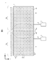
- FIG. 1 is a schematic configuration diagram of a levitation transport apparatus 1 according to an embodiment of the present invention.
- FIG. 2 is an enlarged view of a portion A of the levitation transport apparatus 1 shown in FIG.
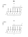
- FIG. 3A is a diagram for explaining a state when the conveyance object 7 passes through the point B in the virtual high precision levitation line L
- FIG. 3B is a diagram in which the conveyance object 7 is virtual. It is a figure for demonstrating the state at the time of passing the C point in the high precision levitation line L.
- FIG. 4A shows a state in which the conveyance object 7 passes through a point D in the line M set on the hole array 21 other than the adjacent hole arrays 21a and 21b with the virtual high-precision levitation line L interposed therebetween.
- 4B is a diagram for explaining the relationship between the hole array 21 and the hole array 21 other than the hole arrays 21a and 21b adjacent to each other with the transport object 7 sandwiching the virtual high-precision levitation line L. It is a figure for demonstrating the state at the time of passing the E point in the line N set on the upper side.
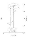
- FIG. 5 is a diagram illustrating a measurement result of the floating amount of the conveyance object 7 from the conveyance surface 20 of the conveyance rail 2 in the levitation conveyance apparatus 1 according to the embodiment of the present invention.
- FIG. 1 is a schematic configuration diagram of a levitation transport apparatus 1 according to the present embodiment.
- FIG. 2 is an enlarged view of part A of the levitation transport apparatus 1 shown in FIG.
- the levitation transport device 1 is configured to transport a transport object 7 (see FIG. 3) such as a glass substrate used in a flat display panel such as a liquid crystal display panel, a plasma display panel, or an organic EL panel.
- Supply rail 2 having a transfer surface 20 for non-contact transfer, an air supply pump 3, and an air supply for connecting the air supply pump 3 to an air supply pump connection port (not shown) of the transfer rail 2.
- Hose 4, suction pump 5, and suction hose 6 for connecting suction pump 5 to a suction pump connection port (not shown) of conveyance rail 2.
- hole arrays 21 are formed that are arranged at a constant interval P ⁇ b> 1 in the conveyance direction X of the conveyance object 7.
- P2 P1
- a virtual high-precision levitation line L is formed above a predetermined adjacent hole array 21a, 21b along a direction Y perpendicular to the transport direction X. Is set.
- the virtual high-accuracy levitation line L is a line indicating a position where high accuracy is required for the flying height of the conveyance object 7 from the conveyance rail 2, such as an optical inspection position of an optical inspection apparatus, a resist coating position of a resist coating apparatus, and the like. Is applicable.
- the adjacent hole arrays 21a and 21b sandwiching the virtual high-accuracy levitation line L with respect to the transport direction X are the air supply holes 22 and the vacuum holes 23 constituting the hole arrays 21a and 21b, respectively. Are arranged so as to be line symmetrical. Further, the air supply holes 22 and the vacuum holes 23 constituting the plurality of hole arrays 21 arranged on the upstream side 24a in the transport direction X with respect to the virtual high-precision levitation line L are alternately arranged at a constant interval P1 in the transport direction X. Has been.
- the air supply holes 22 and the vacuum holes 23 constituting the plurality of hole arrays 21 arranged on the downstream side 24b in the transport direction X with respect to the virtual high precision levitation line L are also alternately arranged at a constant interval P1 in the transport direction X. Has been placed.
- an air supply passage (not shown) that connects the supply pump connection port to the supply hole 22 of each hole array 21, and a suction pump connection port is connected to the vacuum hole 23 of each hole array 21.
- a vacuum air passage (not shown) is formed.
- FIG. 3A is a diagram for explaining a state when the conveyance object 7 passes through a point B (see FIG. 2) in the virtual high precision levitation line L
- FIG. It is a figure for demonstrating the state at the time of the target object 7 passing C point (refer FIG. 2) in the virtual high precision levitation line L shown in FIG. 4A shows a point D in the line M set on the hole array 21 other than the hole arrays 21a and 21b adjacent to the conveyance object 7 with the virtual high-precision levitation line L interposed therebetween (see FIG. 2).
- 4B is a diagram for explaining the state when passing through, and FIG.
- FIG. 4B is an adjacent hole array other than the adjacent hole arrays 21a and 21b with the transport target 7 sandwiching the virtual high-precision levitation line L therebetween. It is a figure for demonstrating the state at the time of passing through the E point (refer FIG. 2) in the line N set up between 21 and the hole array 21.
- FIG. 2 is a figure for demonstrating the state at the time of passing through the E point (refer FIG. 2) in the line N set up between 21 and the hole array 21.
- the virtual high-accuracy levitation line L is set between the adjacent hole array 21a and the hole array 21b, so FIG. 3 (A) and FIG. As shown in (B), when the conveyance object 7 passes through the virtual high precision levitation line L, the air supply hole 22 and the vacuum hole 23 do not exist immediately below the virtual high precision levitation line L, and therefore the air supply hole. It is not affected by the compressed gas ejected from the gas and the gas sucked into the vacuum hole.
- the air supply holes 22 and the vacuum holes 23 constituting the hole arrays 21a and 21b adjacent to each other with the virtual high-accuracy levitation line L interposed therebetween are arranged so as to be symmetrical with respect to the virtual high-accuracy levitation line L. Therefore, the gas flow that the transport object 7 receives immediately before entering the virtual high precision levitation line L is the same as the gas flow that the transport object 7 receives immediately after leaving the virtual high precision levitation line L. Specifically, as shown in FIG. 3 (A), both are compressed gas flows ejected from the air supply holes 22, or both are sucked into the vacuum holes 23 as shown in FIG. 3 (B). Gas flow. For this reason, since the fluctuation
- FIG. 5 is a diagram illustrating a measurement result of the flying height of the object to be transported 7 from the transport surface 20 of the transport rail 2 in the levitation transport apparatus 1 according to the present embodiment.
- the solid line graph 80 is a graph showing the measurement result at the point B in the virtual high precision levitation line L shown in FIG. 2, and the dotted line graph 81 is the measurement result at the point D of the line M shown in FIG.
- a one-dot chain line graph 82 is a graph showing a measurement result at point E in the line N shown in FIG.
- the vertical axis indicates the flying height ( ⁇ m) of the transport object 7 from the transport surface 20
- the horizontal axis indicates each measurement point in the transport direction X of the front end portion of the transport object 7 (the graph 80 indicates B point, graph 81 shows the moving distance (mm) from point D, and graph 82 shows point E). Note that a glass substrate having a length of 200 mm was used for the conveyance object 7.
- the flying height greatly fluctuates.
- the transport object 7 also passes when the transport object 7 passes through the line N set between the adjacent hole array 21 and the hole array 21 other than the hole arrays 21a and 21b. The flying height greatly fluctuates when the leading end portion 7 enters the line N (region F) and when the trailing end portion of the conveyance target portion 7 leaves the line N (region G).
- the tip of the transport object 7 enters the virtual high precision levitation line L (area F) and the transport target.
- the transport object 7 passes through the line M (graph 81) when the rear end of the section 7 leaves the virtual high-precision levitation line L (region G), the transport object 7 is a line. It is proved that it is smaller than the case of passing through N (graph 82), and it is possible to maintain and stabilize the flying height of the conveyance object 7 in the virtual high-precision floating line L with high accuracy.
- each of the air supply holes 22 and the vacuum holes 23 constituting the hole arrays 21a and 21b adjacent to each other with the virtual high-precision levitation line L sandwiched in the transport direction X is replaced with the virtual high-precision levitation line. They are arranged at positions that are line-symmetric with respect to L.
- the air supply holes 22 and the vacuum holes 23 constituting the hole arrays 21a and 21b may be arranged at least at positions where the air supply holes 22 and the vacuum holes 23 face each other with the virtual high-precision levitation line L interposed therebetween. Even in this case, the same effect as the above-described embodiment can be expected.
- a plurality of conveyance rails may be arranged in the conveyance direction X of the conveyance object 7.
- the above-described transfer rail 2 is used only for the transfer rail for which the virtual high-accuracy levitation line L is set, and the conventional transfer rail, that is, the supply rail is used for the transfer rail to which the virtual high-accuracy levitation line L is not set.
- a transport rail in which air holes and vacuum holes are alternately arranged at regular intervals in the transport direction X and the direction Y perpendicular to the transport direction may be used.
- the object to be transported 7 such as a glass substrate used in a flat display panel such as a liquid crystal display panel or a plasma display panel is taken as an example of transport is described as an example.
- the present invention can be widely applied to a levitation conveyance apparatus that levitates and conveys an easy sheet-like conveyance object.
- 1 levitation transport device
- 2 transport rail
- 3 air supply pump
- 4 air supply hose
- 5 suction pump
- 6 suction hose
- 7 object to be transported
- 20 transport surface
- 21, 21a , 21b hole array
- 22 air supply hole
- 23 vacuum hole
Landscapes
- Physics & Mathematics (AREA)
- Engineering & Computer Science (AREA)
- Fluid Mechanics (AREA)
- Mechanical Engineering (AREA)
- Container, Conveyance, Adherence, Positioning, Of Wafer (AREA)
Abstract
仮想高精度浮上ラインにおける搬送対象物の浮上量を高精度に安定させる。浮上搬送装置(1)は、搬送対象物を搬送方向Xに非接触で搬送する搬送用レール(2)を備える。搬送用レール(2)は、気体を噴出する給気孔(22)および気体を吸引するバキューム孔(23)が搬送方向Xに対して垂直な方向に一定間隔で交互に配置された孔アレイ(21)が、搬送方向Xに複数配列された搬送面(20)を備えており、搬送方向Xに対して垂直な方向に沿って設定された仮想高精度浮上ラインLが、搬送方向Xに複数配列された孔アレイ(21)のうち、所定の隣接する孔アレイ(21a)と孔アレイ(21b)との間の上方に位置し、かつ、少なくともこれらの孔アレイ(21a)、(21b)各々を構成する給気孔(22)およびバキューム孔(23)が仮想高精度浮上ラインLに対して線対称となるように配置されている。
Description
本発明は、搬送対象物を浮上させて非接触で搬送する浮上搬送技術に関する。
製造ライン等において、搬送対象物を搬送用レールの搬送面から浮上させて非接触で搬送する浮上搬送装置が知られている。例えば、特許文献1には、液晶ディスプレイパネル、プラズマディスプレイパネル、有機ELパネル等のフラットディスプレイパネルに用いられるガラス基板の光学検査に用いる搬送装置として、ガラス基板を浮上させる搬送用レール(浮上ステージ)と、搬送用レール上に浮上しているガラス基板を搬送する搬送機構と、を備えた浮上搬送装置が開示されている。この浮上搬送装置の搬送用レールには、気体を噴出する給気孔(噴出穴)および気体を吸引するバキューム孔(吸引孔)が、千鳥状、すなわち搬送方向および搬送方向に対して垂直な方向のそれぞれにおいて、一定間隔で交互に配置されている。このように、給気孔とバキューム孔とを均等に配置して、搬送用レールの搬送面から気体の噴出と吸引とを同時に行うことにより、搬送用レールの搬送面からの搬送対象物の浮上高さを一定に保つことができる。
光学検査装置の光学検査位置、レジスト塗布装置のレジスト塗布位置など、搬送用レール上の、搬送対象物の搬送方向に対して垂直な方向に沿って設定された所定のラインにおいて、搬送対象物の搬送用レールからの浮上量に高い精度を求められる場合がある(以下、このようなラインを仮想高精度浮上ラインと呼ぶ)。しかしながら、給気孔およびバキューム孔が千鳥状に均等配置された従来の搬送用レールでは、仮想高精度浮上ラインにおける搬送対象物の浮上量を高精度に安定させることが困難であった。
すなわち、搬送対象物の搬送方向に対して垂直な方向に一定間隔で交互に配置された給気孔およびバキューム孔(以下、孔アレイと呼ぶ)の上に仮想高精度浮上ラインを設定した場合、搬送対象物が仮想高精度浮上ラインを通過する際、仮想高精度浮上ラインの真下に位置する孔アレイの給気孔から噴出する圧縮気体およびこの孔アレイのバキューム孔に吸引される気体の影響を受け、搬送対象物の搬送用レールからの浮上量を高精度に維持し、安定させることができない。
また、隣接する孔アレイの間の上に仮想高精度浮上ラインを設定した場合、仮想高精度浮上ラインを挟んで隣接する孔アレイ各々の給気孔およびバキューム孔の並び順が互いに異なるため、搬送対象物が仮想高精度浮上ラインへ進入直前に受ける気体の流れと、搬送対象物が仮想高精度浮上ラインから離脱直後に受ける気体の流れとが異なる。これにより、孔アレイ上に仮想高精度浮上ラインを設定した場合と同様に、搬送対象物の搬送用レールからの浮上量を高精度に維持し、安定させることができない。
本発明は上記事情に鑑みてなされたものであり、その目的は、仮想高精度浮上ラインにおける搬送対象物の浮上量を高精度に維持し、安定させることができる搬送レールおよび浮上搬送装置を提供することにある。
上記課題を解決するために、本発明では、所定の隣接する孔アレイと孔アレイとの間の上方に仮想高精度浮上ラインを設定するとともに、少なくとも仮想高精度浮上ラインを挟んで隣接する孔アレイ各々の給気孔およびバキューム孔の並び順を、給気孔同士およびバキューム孔同士がそれぞれ仮想高精度浮上ラインを挟んで対向する順番とした。
例えば、本発明の搬送用レールは、気体を用いて搬送対象物を浮上させて、搬送方向に非接触で搬送する搬送用レールであって、
前記気体を噴出する給気孔および気体を吸引するバキューム孔が前記搬送方向に対して垂直な方向に沿って一定間隔で交互に配置された孔アレイが、前記搬送方向に複数配列された搬送面を備え、
前記搬送方向に対して垂直な方向に沿って設定された仮想高精度浮上ラインが、前記搬送方向に複数配列された前記孔アレイのうち、搬送方向において隣接する所定の孔アレイと孔アレイとの間の上方に位置するとともに、少なくとも当該隣接する所定の孔アレイのうちの一方を構成する給気孔が他方を構成する給気孔と前記仮想高精度浮上ラインを挟んで対向し、かつ当該隣接する所定の孔アレイのうちの一方を構成するバキューム孔が他方を構成するバキューム孔と前記仮想高精度浮上ラインを挟んで対向する位置に配置されている。
前記気体を噴出する給気孔および気体を吸引するバキューム孔が前記搬送方向に対して垂直な方向に沿って一定間隔で交互に配置された孔アレイが、前記搬送方向に複数配列された搬送面を備え、
前記搬送方向に対して垂直な方向に沿って設定された仮想高精度浮上ラインが、前記搬送方向に複数配列された前記孔アレイのうち、搬送方向において隣接する所定の孔アレイと孔アレイとの間の上方に位置するとともに、少なくとも当該隣接する所定の孔アレイのうちの一方を構成する給気孔が他方を構成する給気孔と前記仮想高精度浮上ラインを挟んで対向し、かつ当該隣接する所定の孔アレイのうちの一方を構成するバキューム孔が他方を構成するバキューム孔と前記仮想高精度浮上ラインを挟んで対向する位置に配置されている。
ここで、前記隣接する所定の孔アレイ各々を構成する給気孔およびバキューム孔は、前記仮想高精度浮上ラインに対して線対称となる位置に配置されていてもよい。また、前記仮想高精度浮上ラインに対して前記搬送方向の上流側に配置された複数の孔アレイ、および前記仮想高精度浮上ラインに対して前記搬送方向の下流側に配置された複数の孔アレイは、それぞれ、各孔アレイを構成する給気孔およびバキューム孔が前記搬送方向において一定間隔で交互に配置されていてもよい。
また、例えば、本発明の浮上搬送装置は、気体を用いて搬送対象物を浮上させて、搬送方向に非接触で搬送する浮上搬送装置であって、
前記搬送用レールと、
前記搬送用レールの前記搬送面の前記給気孔から噴出する圧縮気体を供給するための給気ポンプと、
前記搬送用レールの前記搬送面の前記バキューム孔に気体を吸引するための吸引ポンプと、を備える。
前記搬送用レールと、
前記搬送用レールの前記搬送面の前記給気孔から噴出する圧縮気体を供給するための給気ポンプと、
前記搬送用レールの前記搬送面の前記バキューム孔に気体を吸引するための吸引ポンプと、を備える。
本発明では、隣接する孔アレイと孔アレイとの間の上方に仮想高精度浮上ラインが位置しているので、搬送対象物がこの仮想高精度浮上ラインを通過する際、この仮想高精度浮上ラインの下方に孔アレイは存在せず、したがって給気孔から噴出する圧縮気体およびバキューム孔に吸引される気体の影響を受けない。また、少なくとも仮想高精度浮上ラインを挟んで隣接する孔アレイ各々を構成する給気孔およびバキューム孔の並び順を、給気孔同士およびバキューム孔同士がそれぞれ仮想高精度浮上ラインを挟んで対向する順番としたので、搬送対象物が仮想高精度浮上ラインへ進入直前に受ける気体の流れと、搬送対象物が仮想高精度浮上ラインから離脱直後に受ける気体の流れとが同じになる。このため、仮想高精度浮上ラインにおける気体の流れの変動を小さくできるので、仮想高精度浮上ラインにおける搬送対象物の浮上量を高精度に維持し、安定させることができる。
以下、本発明の一実施の形態について、図面を参照して説明する。
図1は、本実施の形態に係る浮上搬送装置1の概略構成図である。また、図2は、図1に示す浮上搬送装置1のA部拡大図である。
図示するように、本実施の形態に係る浮上搬送装置1は、液晶ディスプレイパネル、プラズマディスプレイパネル、有機ELパネル等のフラットディスプレイパネルに用いられるガラス基板等の搬送対象物7(図3参照)を非接触で搬送するための搬送面20を備えた搬送用レール2と、給気ポンプ3と、給気ポンプ3を搬送レール2の給気ポンプ接続口(不図示)に接続するための給気用ホース4と、吸引ポンプ5と、吸引ポンプ5を搬送レール2の吸引ポンプ接続口(不図示)に接続するための吸引用ホース6と、を備えている。
搬送レール2の搬送面20には、搬送対象物7の搬送方向Xにおいて一定間隔P1で配列された孔アレイ21が形成されている。各孔アレイ21は、圧縮気体を噴出する給気孔22および気体を吸引するバキューム孔23が搬送方向Xに対して垂直な方向Yに沿って一定間隔P2(例えばP2=P1)で交互に配置されて構成されている。なお、図の簡略化のため、一部の給気孔22およびバキューム孔23にのみ符号を付している。
搬送方向Xに複数配列された孔アレイ21のうち、所定の隣接する孔アレイ21a、21bの間の上方には、搬送方向Xに対して垂直な方向Yに沿って仮想高精度浮上ラインLが設定されている。仮想高精度浮上ラインLは、搬送対象物7の搬送用レール2からの浮上量に高い精度を求められる位置を示すラインであり、光学検査装置の光学検査位置、レジスト塗布装置のレジスト塗布位置などが該当する。
仮想高精度浮上ラインLを搬送方向Xに対して挟んで隣接する孔アレイ21a、21bは、これらの孔アレイ21a、21bを構成する給気孔22およびバキューム孔23のそれぞれが仮想高精度浮上ラインLに対して線対称となるように配置されている。また、仮想高精度浮上ラインLに対して搬送方向Xの上流側24aに配置された複数の孔アレイ21を構成する給気孔22およびバキューム孔23は、搬送方向Xにおいて一定間隔P1で交互に配置されている。同様に、仮想高精度浮上ラインLに対して搬送方向Xの下流側24bに配置された複数の孔アレイ21を構成する給気孔22およびバキューム孔23も、搬送方向Xにおいて一定間隔P1で交互に配置されている。
搬送レール2の内部には、給気ポンプ接続口を各孔アレイ21の給気孔22に繋ぐ給気用通気路(不図示)、および吸引ポンプ接続口を各孔アレイ21のバキューム孔23に繋ぐバキューム用通気路(不図示)が形成されている。
図3(A)は、搬送対象物7が仮想高精度浮上ラインL内のB点(図2参照)を通過する際の状態を説明するための図であり、図3(B)は、搬送対象物7が図2に示す仮想高精度浮上ラインL内のC点(図2参照)を通過する際の状態を説明するための図である。また、図4(A)は、搬送対象物7が仮想高精度浮上ラインLを挟んで隣接する孔アレイ21a、21b以外の孔アレイ21上に設定されたラインM内のD点(図2参照)を通過する際の状態を説明するための図であり、図4(B)は、搬送対象物7が仮想高精度浮上ラインLを挟んで隣接する孔アレイ21a、21b以外の隣接する孔アレイ21と孔アレイ21との間の上に設定されたラインN内のE点(図2参照)を通過する際の状態を説明するための図である。
図4(A)に示すように、搬送対象物7が孔アレイ21a、21b以外の孔アレイ21上に設定されたラインMを通知する際、仮想高精度浮上ラインの真下に位置する孔アレイ21の給気孔22から噴出する圧縮気体およびこの孔アレイ21のバキューム孔23に吸引される気体の影響を受け、ラインMにおける搬送対象物7の搬送用レール2からの浮上量を高精度に維持し、安定させることができない。
また、図4(B)に示すように、搬送対象物7が孔アレイ21a、21b以外の隣接する孔アレイ21と孔アレイ21との間の上に設定されたラインNを通過する際、このラインNを挟んで隣接する孔アレイ21各々の給気孔22およびバキューム孔23の並び順が互いに異なるため、搬送対象物7がラインNへ進入直前に受ける気体の流れと、搬送対象物7がラインNから離脱直後に受ける気体の流れとが異なる。具体的には、搬送対象物7がラインNへ進入直前に受ける気体の流れおよび搬送対象物7がラインNから離脱直後に受ける気体の流れの一方が給気孔22から噴出される圧縮気体の流れとなり、他方がバキューム孔23に吸引される気体の流れになる。このため、ラインNにおける搬送対象物7の搬送用レール2からの浮上量を高精度に維持し、安定させることができない。
しかし、本実施の形態に係る浮上搬送装置1では、隣接する孔アレイ21aと孔アレイ21bとの間の上に仮想高精度浮上ラインLを設定しているので、図3(A)および図3(B)に示すように、搬送対象物7がこの仮想高精度浮上ラインLを通過する際、この仮想高精度浮上ラインLの真下に給気孔22およびバキューム孔23は存在せず、したがって給気孔から噴出する圧縮気体およびバキューム孔に吸引される気体の影響を受けない。
また、仮想高精度浮上ラインLを挟んで隣接する孔アレイ21a、21bをそれぞれ構成する給気孔22およびバキューム孔23が、仮想高精度浮上ラインLに対して線対称となるように配置されているので、搬送対象物7が仮想高精度浮上ラインLへ進入直前に受ける気体の流れと、搬送対象物7が仮想高精度浮上ラインLから離脱直後に受ける気体の流れとが同じになる。具体的には、図3(A)に示すように、ともに給気孔22から噴出される圧縮気体の流れになるか、あるいは、図3(B)に示すように、ともにバキューム孔23に吸引される気体の流れになる。このため、仮想高精度浮上ラインLにおける気体の流れの変動を小さくできるので、仮想高精度浮上ラインLにおける搬送対象物7の浮上量を高精度に維持し、安定させることができる。
図5は、本実施の形態に係る浮上搬送装置1において、搬送対象物7の、搬送用レール2の搬送面20からの浮上量の測定結果を示す図である。
ここで、実線のグラフ80は、図2に示す仮想高精度浮上ラインL内のB点における測定結果を示すグラフであり、点線のグラフ81は、図2に示すラインMのD点における測定結果を示すグラフであり、一点鎖線のグラフ82は、図2に示すラインN内のE点における測定結果を示すグラフである。
また、縦軸は、搬送対象物7の搬送面20からの浮上量(μm)を示しており、横軸は、搬送対象物7の先端部の、搬送方向Xにおける各測定点(グラフ80はB点、グラフ81はD点、グラフ82はE点)からの移動距離(mm)を示している。なお、搬送対象物7には、長さ200mmのガラス基板を用いた。
グラフ81に示すように、搬送対象物7が孔アレイ21a、21b以外の孔アレイ21上に設定されたラインMを通過する場合、搬送対象物7の先端部のラインMへの進入時(領域F)および搬送対象部7の後端部のラインMからの離脱時(領域G)において、浮上量が大きく変動している。また、グラフ82に示すように、搬送対象物7が孔アレイ21a、21b以外の隣接する孔アレイ21と孔アレイ21との間の上に設定されたラインNを通過する場合も、搬送対象物7の先端部のラインNへの進入時(領域F)および搬送対象部7の後端部のラインNからの離脱時(領域G)において、浮上量が大きく変動している。
一方、グラフ80に示すように、搬送対象物7が仮想高精度浮上ラインLを通過する場合、搬送対象物7の先端部の仮想高精度浮上ラインLへの進入時(領域F)および搬送対象部7の後端部の仮想高精度浮上ラインLからの離脱時(領域G)における浮上量の変動が、搬送対象物7がラインMを通過する場合(グラフ81)および搬送対象物7がラインNを通過する場合(グラフ82)に比べて小さく、仮想高精度浮上ラインLにおける搬送対象物7の浮上量を高精度に維持し、安定させることが可能であることが証明された。
なお、本発明は、上記の実施の形態に限定されるものではなく、その要旨の範囲内で数々の変形が可能である。
例えば、上記の実施の形態では、仮想高精度浮上ラインLを搬送方向Xに対して挟んで隣接する孔アレイ21a、21bを構成する給気孔22およびバキューム孔23のそれぞれを、仮想高精度浮上ラインLに対して線対称となる位置に配置した。しかし、本発明はこれに限定されない。少なくとも、給気孔22同士およびバキューム孔23同士がそれぞれ仮想高精度浮上ラインLを挟んで対向する位置に、孔アレイ21a、21bを構成する給気孔22およびバキューム孔23のそれぞれを配置すればよい。この場合でも上記の実施の形態と同様の効果が期待できる。
また、上記の実施の形態に係る浮上搬送装置1において、搬送対象物7の搬送方向Xに搬送用レールを複数配置してもよい。この場合、仮想高精度浮上ラインLが設定される搬送用レールにのみ上述の搬送用レール2を用い、仮想高精度浮上ラインLが設定されない搬送用レールには、従来の搬送用レール、すなわち給気孔およびバキューム孔が搬送方向Xおよび搬送方向に対して垂直な方向Yのそれぞれにおいて、一定間隔で交互に配置された搬送用レールを用いてもよい。
また、上記の実施の形態では、液晶ディスプレイパネル、プラズマディスプレイパネル等のフラットディスプレイパネルに用いられるガラス基板等の搬送対象物7を搬送対象とする場合を例に挙げたが、本発明は、撓みやすいシート状の搬送対象物を浮上搬送する浮上搬送装置に広く適用できる。
1:浮上搬送装置、 2:搬送用レール、 3:給気ポンプ、 4:給気用ホース、 5:吸引ポンプ、 6:吸引用ホース、 7:搬送対象物、 20:搬送面、 21、21a、21b:孔アレイ、 22:給気孔、 23:バキューム孔
Claims (4)
- 気体を用いて搬送対象物を浮上させて、搬送方向に非接触で搬送する搬送用レールであって、
前記気体を噴出する給気孔および気体を吸引するバキューム孔が前記搬送方向に対して垂直な方向に沿って一定間隔で交互に配置された孔アレイが、前記搬送方向に複数配列された搬送面を備え、
前記搬送方向に対して垂直な方向に沿って設定された仮想高精度浮上ラインが、前記搬送方向に複数配列された前記孔アレイのうち、搬送方向において隣接する所定の孔アレイと孔アレイとの間の上方に位置するとともに、少なくとも当該隣接する所定の孔アレイのうちの一方を構成する給気孔が他方を構成する給気孔と前記仮想高精度浮上ラインを挟んで対向し、かつ当該隣接する所定の孔アレイのうちの一方を構成するバキューム孔が他方を構成するバキューム孔と前記仮想高精度浮上ラインを挟んで対向する位置に配置されている
ことを特徴とする搬送用レール。 - 請求項1に記載の搬送用レールであって、
前記隣接する所定の孔アレイ各々を構成する給気孔およびバキューム孔は、前記仮想高精度浮上ラインに対して線対称となる位置に配置されている
ことを特徴とする搬送用レール。 - 請求項1または2に記載の搬送用レールであって、
前記仮想高精度浮上ラインに対して前記搬送方向の上流側に配置された複数の孔アレイ、および前記仮想高精度浮上ラインに対して前記搬送方向の下流側に配置された複数の孔アレイは、それぞれ、各孔アレイを構成する給気孔およびバキューム孔が前記搬送方向において一定間隔で交互に配置されている
ことを特徴とする搬送用レール。 - 気体を用いて搬送対象物を浮上させて、搬送方向に非接触で搬送する浮上搬送装置であって、
請求項1ないし3のいずれか一項に記載の搬送用レールと、
前記搬送用レールの前記搬送面の前記給気孔から噴出する圧縮気体を供給するための給気ポンプと、
前記搬送用レールの前記搬送面の前記バキューム孔に気体を吸引するための吸引ポンプと、を備える
ことを特徴とする浮上搬送装置。
Applications Claiming Priority (2)
| Application Number | Priority Date | Filing Date | Title |
|---|---|---|---|
| JP2014104782A JP2015218055A (ja) | 2014-05-20 | 2014-05-20 | 搬送用レールおよび浮上搬送装置 |
| JP2014-104782 | 2014-05-20 |
Publications (1)
| Publication Number | Publication Date |
|---|---|
| WO2015178189A1 true WO2015178189A1 (ja) | 2015-11-26 |
Family
ID=54553863
Family Applications (1)
| Application Number | Title | Priority Date | Filing Date |
|---|---|---|---|
| PCT/JP2015/063024 Ceased WO2015178189A1 (ja) | 2014-05-20 | 2015-04-30 | 搬送用レールおよび浮上搬送装置 |
Country Status (3)
| Country | Link |
|---|---|
| JP (1) | JP2015218055A (ja) |
| TW (1) | TW201609512A (ja) |
| WO (1) | WO2015178189A1 (ja) |
Citations (5)
| Publication number | Priority date | Publication date | Assignee | Title |
|---|---|---|---|---|
| JP2004279335A (ja) * | 2003-03-18 | 2004-10-07 | Olympus Corp | 基板検査装置 |
| JP2005132626A (ja) * | 2003-10-06 | 2005-05-26 | Sumitomo Heavy Ind Ltd | 搬送装置、塗布システム、及び検査システム |
| JP2008505041A (ja) * | 2004-07-09 | 2008-02-21 | オー・ツェー・エリコン・バルザース・アクチェンゲゼルシャフト | ガスベアリング基板装填機構 |
| JP2010232472A (ja) * | 2009-03-27 | 2010-10-14 | Dainippon Screen Mfg Co Ltd | 基板搬送装置および基板処理装置 |
| JP2011124342A (ja) * | 2009-12-09 | 2011-06-23 | Tokyo Electron Ltd | 基板処理装置、基板処理方法及びこの基板処理方法を実行させるためのプログラムを記録した記録媒体 |
-
2014
- 2014-05-20 JP JP2014104782A patent/JP2015218055A/ja active Pending
-
2015
- 2015-04-30 WO PCT/JP2015/063024 patent/WO2015178189A1/ja not_active Ceased
- 2015-05-01 TW TW104114053A patent/TW201609512A/zh unknown
Patent Citations (5)
| Publication number | Priority date | Publication date | Assignee | Title |
|---|---|---|---|---|
| JP2004279335A (ja) * | 2003-03-18 | 2004-10-07 | Olympus Corp | 基板検査装置 |
| JP2005132626A (ja) * | 2003-10-06 | 2005-05-26 | Sumitomo Heavy Ind Ltd | 搬送装置、塗布システム、及び検査システム |
| JP2008505041A (ja) * | 2004-07-09 | 2008-02-21 | オー・ツェー・エリコン・バルザース・アクチェンゲゼルシャフト | ガスベアリング基板装填機構 |
| JP2010232472A (ja) * | 2009-03-27 | 2010-10-14 | Dainippon Screen Mfg Co Ltd | 基板搬送装置および基板処理装置 |
| JP2011124342A (ja) * | 2009-12-09 | 2011-06-23 | Tokyo Electron Ltd | 基板処理装置、基板処理方法及びこの基板処理方法を実行させるためのプログラムを記録した記録媒体 |
Also Published As
| Publication number | Publication date |
|---|---|
| TW201609512A (zh) | 2016-03-16 |
| JP2015218055A (ja) | 2015-12-07 |
Similar Documents
| Publication | Publication Date | Title |
|---|---|---|
| JP2011225355A (ja) | エア浮上ユニット、ステージ装置、検査システム、露光システム及び塗布システム | |
| KR101434169B1 (ko) | 에어블로윙 타입 기판 부상 및 이송 장치 | |
| JP2003063643A (ja) | 薄板の搬送方法及び装置 | |
| TWI637928B (zh) | Glass plate manufacturing method and glass plate manufacturing device | |
| JP6518891B2 (ja) | 搬送装置 | |
| CN106144594B (zh) | 用来运送平板构件的输送载具 | |
| CN108249159A (zh) | 浮起搬运装置以及基板处理装置 | |
| WO2015178189A1 (ja) | 搬送用レールおよび浮上搬送装置 | |
| CN104066664B (zh) | 浮动运输设备和浮动运输方法 | |
| JP6147521B2 (ja) | 浮上搬送装置、搬送レール、および浮上搬送方法 | |
| KR102588108B1 (ko) | 유리판의 제조 방법 및 그 제조 장치 | |
| JP2008076170A (ja) | 基板検査装置 | |
| JP4171293B2 (ja) | 薄板状材の搬送方法及び装置 | |
| JP4392692B2 (ja) | 半導体ウエハー及び液晶ガラスエアー浮上搬送装置 | |
| JP2007204278A (ja) | 基板浮上搬送装置 | |
| JP4629007B2 (ja) | 薄板状材料搬送用エアテーブル及び薄板状材料搬送装置 | |
| JP2008130892A (ja) | エア浮上搬送装置、およびエア搬送方法 | |
| CN109843822A (zh) | 玻璃基板的制造方法 | |
| JP2016016989A (ja) | 搬送用レールおよび浮上搬送装置 | |
| KR102497947B1 (ko) | 유리판의 제조 방법 및 그 제조 장치 | |
| CN109790064A (zh) | 玻璃基板的制造方法 | |
| TWI668173B (zh) | 浮上搬送裝置及基板處理裝置 | |
| CN211337934U (zh) | 基板输送装置 | |
| JP2012101897A (ja) | 搬送装置 | |
| WO2021100392A1 (ja) | ガラス板の製造装置及びその製造方法 |
Legal Events
| Date | Code | Title | Description |
|---|---|---|---|
| 121 | Ep: the epo has been informed by wipo that ep was designated in this application |
Ref document number: 15795784 Country of ref document: EP Kind code of ref document: A1 |
|
| NENP | Non-entry into the national phase |
Ref country code: DE |
|
| 32PN | Ep: public notification in the ep bulletin as address of the adressee cannot be established |
Free format text: NOTING OF LOSS OF RIGHTS PURSUANT TO RULE 112(1)M EPC ( EPO FORM 1205A DATED 16-02-2017) |
|
| 122 | Ep: pct application non-entry in european phase |
Ref document number: 15795784 Country of ref document: EP Kind code of ref document: A1 |