WO2015174375A1 - 研磨テーブル交換装置、研磨テーブルの交換方法、および半導体デバイス製造装置の構成部品を交換する装置 - Google Patents
研磨テーブル交換装置、研磨テーブルの交換方法、および半導体デバイス製造装置の構成部品を交換する装置 Download PDFInfo
- Publication number
- WO2015174375A1 WO2015174375A1 PCT/JP2015/063500 JP2015063500W WO2015174375A1 WO 2015174375 A1 WO2015174375 A1 WO 2015174375A1 JP 2015063500 W JP2015063500 W JP 2015063500W WO 2015174375 A1 WO2015174375 A1 WO 2015174375A1
- Authority
- WO
- WIPO (PCT)
- Prior art keywords
- polishing table
- polishing
- crane
- frame
- movable frame
- Prior art date
- Legal status (The legal status is an assumption and is not a legal conclusion. Google has not performed a legal analysis and makes no representation as to the accuracy of the status listed.)
- Ceased
Links
Images








Classifications
-
- B—PERFORMING OPERATIONS; TRANSPORTING
- B24—GRINDING; POLISHING
- B24B—MACHINES, DEVICES, OR PROCESSES FOR GRINDING OR POLISHING; DRESSING OR CONDITIONING OF ABRADING SURFACES; FEEDING OF GRINDING, POLISHING, OR LAPPING AGENTS
- B24B37/00—Lapping machines or devices; Accessories
- B24B37/11—Lapping tools
- B24B37/20—Lapping pads for working plane surfaces
-
- B—PERFORMING OPERATIONS; TRANSPORTING
- B24—GRINDING; POLISHING
- B24B—MACHINES, DEVICES, OR PROCESSES FOR GRINDING OR POLISHING; DRESSING OR CONDITIONING OF ABRADING SURFACES; FEEDING OF GRINDING, POLISHING, OR LAPPING AGENTS
- B24B37/00—Lapping machines or devices; Accessories
- B24B37/34—Accessories
-
- H—ELECTRICITY
- H10—SEMICONDUCTOR DEVICES; ELECTRIC SOLID-STATE DEVICES NOT OTHERWISE PROVIDED FOR
- H10P—GENERIC PROCESSES OR APPARATUS FOR THE MANUFACTURE OR TREATMENT OF DEVICES COVERED BY CLASS H10
- H10P52/00—Grinding, lapping or polishing of wafers, substrates or parts of devices
Definitions
- the present invention relates to an apparatus and method for exchanging a polishing table used in a polishing apparatus for polishing a substrate such as a wafer.
- the present invention relates to an apparatus and a method for realizing simple maintenance while restricting a maintenance space from the viewpoint of increasing the size of a polishing table and improving productivity per footprint as the wafer size increases.
- the present invention also relates to an apparatus for exchanging components of a semiconductor device manufacturing apparatus represented by a polishing apparatus for polishing a substrate such as a wafer.
- a CMP apparatus that is one of semiconductor device manufacturing apparatuses is a polishing apparatus that chemically and mechanically polishes a wafer.
- One of the largest components in a CMP apparatus is a polishing table.
- This polishing table is a surface plate-like rotating body that is mounted horizontally on a table shaft and has a polishing pad attached to the surface thereof.
- This polishing table is a large and heavy part and cannot be replaced manually. For this reason, a series of operations are performed in which a dedicated lifter is prepared, the polishing table is lifted in the CMP apparatus, moved horizontally, pulled out of the CMP apparatus, and placed on a receiving table.
- the polishing table is pulled out horizontally and placed on the receiving table, a maintenance space larger than the diameter of the polishing table is required.
- the maintenance space necessary for exchanging the polishing table is 900 mm.
- the polishing table diameter exceeds 1000 mm, it is difficult to replace the polishing table in the conventional maintenance space of 900 mm.
- the lifter is also provided with a fixed frame at the same height as the upper frame of the semiconductor device manufacturing apparatus.
- the upper frame of the semiconductor device manufacturing apparatus and the fixed frame of the lifter are connected by a connection bracket.
- a crane is disposed immediately below the fixed frame, and the crane lifts the component parts of the semiconductor device manufacturing apparatus and pulls the component parts out of the semiconductor device manufacturing apparatus.
- the lifter fixing frame is connected to the upper frame of the semiconductor device manufacturing apparatus as described above. Therefore, the fixed frame is at a high position, and the center of gravity of the lifter is increased. For this reason, the lifter has a wide shape in order to prevent the lifter from falling over when it is carried in. However, if the lifter has a wide shape, the lifter cannot be carried in smoothly if the passage width in the manufacturing plant is limited.
- connection bracket In order to attach the connection bracket to the upper frame of the semiconductor device manufacturing apparatus, it is necessary to lift the connection bracket itself to the upper frame. However, the weight of the connection bracket is about 20 kg, and it is dangerous to lift the connection bracket to the upper frame by human power. For this reason, the apparatus for lifting a connection bracket was separately needed.
- An object of the present invention is to provide a polishing table exchanging apparatus and a polishing table exchanging method capable of exchanging a large polishing table with a small maintenance space. It is another object of the present invention to provide a component replacement device that has a low center of gravity and can eliminate the need for a dedicated device for lifting a connection bracket for connection to a semiconductor device manufacturing apparatus.
- One aspect of the present invention is a polishing table exchange device for removing a polishing table from a polishing apparatus, a crane that moves the polishing table in a vertical direction and a horizontal direction, and a table base on which the polishing table is placed.
- a polishing table exchanging apparatus comprising a table table tilting mechanism for tilting the table table.
- the polishing table exchanging apparatus as a whole is further provided with a moving mechanism that is movable.
- the apparatus further includes a connecting portion connected to the polishing apparatus.
- the crane includes a lift arm that is extendable in a horizontal direction, a table support that is attached to a tip of the lift arm, and that supports the polishing table, and a vertical movement device that moves the lift arm up and down. It is characterized by having.
- the polishing table is raised, the raised polishing table is moved in the horizontal direction, the polishing table is taken out of the polishing apparatus, the polishing table is placed on a table base, and the table base is placed on the table base.
- a polishing table exchange method characterized by tilting together with a polishing table.
- Still another aspect of the present invention is a component replacement apparatus used for replacement of a component of a semiconductor device manufacturing apparatus, wherein the vertical frame extends in the vertical direction, and the movable frame is movable up and down along the vertical frame. And a connecting member that is fixed to the movable frame and connects the semiconductor device manufacturing apparatus and the movable frame, a crane that is positioned below the movable frame and that can move up and down along the vertical frame, A lifting device that lifts and lowers the crane and the movable frame along the vertical frame is provided.
- the movable frame and the crane can move up and down independently of each other, the lifting device is connected to the crane, and the movable frame and the crane are located below the movable frame.
- a frame stopper is provided for restricting the movement to the position.
- a preferable aspect further includes a base frame fixed to a lower portion of the vertical frame, and a crane stopper provided between the base frame and the crane and restricting the downward movement of the crane.
- the crane includes a pivot shaft extending in a vertical direction, a rail that can pivot horizontally around the pivot shaft, and a movable pulley that can move on the rail in the longitudinal direction of the rail. It is characterized by that.
- the connecting member is detachably fixed to the movable frame by a screw.
- the apparatus and method of the present invention are indispensable for simultaneously realizing productivity improvement by increasing the number of polishing apparatuses, in addition to productivity improvement by increasing the wafer size.
- the center of gravity of the entire component replacement device can be lowered by lowering the movable frame and crane. Therefore, the possibility of falling when moving the component replacement device is reduced, and the width of the component replacement device itself can be designed to be small. Therefore, there are effects such as reduction of member cost, reduction of transportation cost, and reduction of storage space. Furthermore, even when the passage width in the factory is limited, the component replacement device can be smoothly moved through the passage.
- exchange apparatus which is a jig
- exchange apparatus component replacement
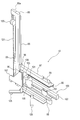
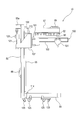
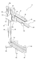
- a perspective view of a polishing table exchange device It is a side view which shows the state which the crane and the movable frame raised. It is a perspective view which shows the state which the crane and the movable frame raised. It is a side view which shows the state which connected the movable frame to the upper frame of the grinding
- FIG. 1 is a perspective view schematically showing a polishing apparatus.
- a polishing apparatus (also referred to as a CMP apparatus) 1, which is an example of a semiconductor device manufacturing apparatus, polishes a wafer W by pressing the wafer W against the polishing table 3 for supporting the polishing pad 2 and the polishing pad 2 on the polishing table 3.
- a polishing liquid supply nozzle 5 for supplying a polishing liquid (usually slurry) onto the polishing pad 2.
- the polishing table 3 is connected to a table motor 6 disposed below the table shaft 3a, and the polishing table 3 is rotated by the table motor 6 in a direction indicated by an arrow.
- a polishing pad 2 is affixed to the upper surface of the polishing table 3, and the upper surface of the polishing pad 2 constitutes a polishing surface 2a for polishing the wafer W.
- the polishing head 4 is connected to the lower end of the head shaft 7.
- the polishing head 4 is configured to hold the wafer W on the lower surface thereof by vacuum suction.
- the head shaft 7 is moved up and down by a vertical movement mechanism (not shown).
- the polishing of the wafer W is performed as follows.
- the polishing head 4 and the polishing table 3 are rotated in directions indicated by arrows, respectively, and a polishing liquid (slurry) is supplied onto the polishing pad 2 from the polishing liquid supply nozzle 5.
- a polishing liquid slurry
- the polishing head 4 presses the wafer W against the polishing surface 2 a of the polishing pad 2.
- the surface of the wafer W is polished by the mechanical action of abrasive grains contained in the polishing liquid and the chemical action of the polishing liquid.
- FIG. 2 is a side view showing the polishing table exchange device 10 which is a jig for exchanging the polishing table 3.
- the polishing table exchanging device 10 supports the polishing table 3 and moves the polishing table 3 in the vertical and horizontal directions, a table base 14 on which the polishing table 3 is placed, and the table base 14 is tilted.
- a power jack 15 as a table base tilting mechanism is provided.
- the crane 12 includes a lift arm 21 that can be expanded and contracted in the horizontal direction, a handle 22 that is gripped by a hand when the lift arm 21 is expanded and contracted in the horizontal direction, and an arm lock mechanism 23 that fixes the tip position of the lift arm 21.
- a plurality of chains (table support tools) 24 attached to the tip of the lift arm 21 for supporting the polishing table 3, an arm holder 26 for holding the lift arm 21, and the arm holder 26 and the lift arm 21.
- a winch 30 as a vertically moving device that moves up and down integrally.
- the lift arm 21 of this embodiment is a telescopic arm.
- the arm holder 26 is supported by a plurality of linear guides 33 attached to a plurality of vertical frames 16 extending in the vertical direction so as to be movable in the vertical direction.
- the winch 30 is attached to a horizontal frame 17 fixed to the vertical frame 16.
- the vertical frame 16 and the horizontal frame 17 constitute a housing 18 of the polishing table exchange device 10.
- the crane 12, the table base 14, and the power jack 15 are attached to the housing 18.
- the winch 30 and the arm holder 26 are connected by a wire rope (not shown).
- a wire rope not shown.
- the winch 30 winds up the wire rope
- the arm holder 26 and the lift arm 21 held by the arm holder 26 are raised together.
- the winch 30 unwinds the wire rope
- the arm holder 26 and the lift arm 21 descend due to their own weight.
- the vertical movement of the arm holder 26 and the lift arm 21 is guided in the vertical direction by the linear guide 33.
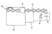
- FIG. 3 is a bottom view showing the lift arm 21 and the arm lock mechanism 23.
- the arm lock mechanism 23 includes a pantograph mechanism.
- the arm lock mechanism 23 is disposed along the lift arm 21, and the arm lock mechanism 23 is supported by a bracket 27.
- One end of the arm lock mechanism 23 is connected to the tip of the lift arm 21, and the other end of the arm lock mechanism 23 is connected to the arm holder 26.
- the handle 22 is fixed to the tip of the lift arm 21.
- the arm lock mechanism 23 When the handle 22 is grasped by hand and the lift arm 21 is manually expanded and contracted, the arm lock mechanism 23 is expanded and contracted in the same manner.
- the arm lock mechanism 23 includes a lock lever 23a that fixes the length thereof, and the entire length of the arm lock mechanism 23 is fixed by manually operating the lock lever 23a. Therefore, the horizontal length of the lift arm 21 connected to the arm lock mechanism 23 is fixed, and the position of the tip of the lift arm 21 is fixed.
- an actuator for example, a combination of a motor and a ball screw
- an actuator for example, a combination of a motor and a ball screw
- FIG. 4 is a plan view showing the polishing table 3 to which a chain 24 as a table support is connected.
- three chains 24 are used, and the polishing table 3 is suspended from the lift arm 21 by these three chains 24.
- a first suspension bracket 41 and a second suspension bracket 42 are attached to the periphery of the polishing table 3.
- the first suspension bracket 41 and the second suspension bracket 42 are arranged symmetrically with respect to the center of the polishing table 3.
- the first suspension bracket 41 includes one connection ring (eye bolt) 44
- the second suspension bracket 42 includes two connection rings (eye bolts) 45 and 46.
- One of the three chains 24 is attached to the connection ring 44 of the first suspension bracket 41, and the other two are attached to the connection rings 45 and 46 of the second suspension bracket 42.
- the other ends of the three chains 24 are connected to a mounting portion 48 fixed to the tip of the lift arm 21.
- FIG. 5 is a perspective view showing the table base 14.
- the table base 14 includes two support arms 51 that are parallel to each other, a connecting arm 52 that connects the two support arms 51, and an arm that is fixed to the two support arms 51.
- a shaft 54 is provided.
- These support arms 51 have a horizontal table mounting surface 51a. Further, these support arms 51 each have two claws 51b extending vertically at their tips.
- Bearings (not shown) are fixed to the two support frames 57 extending vertically, and the arm shaft 54 extending horizontally is rotatably supported by these bearings. Therefore, the table base 14 is configured to be able to rotate around the axis of the arm shaft 54.
- the support frame 57 constitutes the housing 18 together with the vertical frame 16 and the horizontal frame 17.
- a locking member 61 is fixed to the end of the arm shaft 54, and the locking member 61 rotates together with the arm shaft 54.
- An arm stopper (upper arm stopper) 64 fixed to the support frame 57 is disposed above the locking member 61.
- an arm stopper (lower arm stopper) 65 is disposed below the table base 14.
- the lower surface of the table base 14 comes into contact with the arm stopper 65 so that the table base 14 does not tilt further downward. Accordingly, the range of inclination of the table base 14 is limited by the upper arm stopper 64 and the lower arm stopper 65.
- a power jack (table base tilting mechanism) 15 is connected to the connecting arm 52 (see FIG. 5) of the table base 14.
- the power jack 15 is provided with a handle 15a. When the handle 15a is turned, the table base 14 rotates downward about the arm shaft 54, and thereby the table base 14 tilts downward.
- a plurality of rollers 69 as a moving mechanism are fixed to a base frame 67 that constitutes a part of the casing 18 of the polishing table exchange device 10. These rollers 69 allow the polishing table exchange device 10 itself to move with the polishing table 3 and transport the polishing table 3 to a desired location.
- the polishing table exchange device 10 is moved and brought into contact with the frames 1 a and 1 b of the polishing device 1.
- the polishing table exchanging device 10 has a plurality of connecting portions 71 and 72 that are detachably connected to the frames 1 a and 1 b of the polishing device 1.
- two connecting portions 71 and 72 are provided at the upper and lower portions of the housing 18. These connecting portions 71 and 72 are connected to the frames 1 a and 1 b of the polishing apparatus 1 by bolts (not shown), respectively, whereby the entire polishing table exchange apparatus 10 is fixed to the polishing apparatus 1.
- the polishing table 3 and the lift arm 21 are connected by a chain 24.
- the first suspension bracket 41 and the second suspension bracket 42 are attached to the polishing table 3, and the chain 24 is connected to the polishing table 3 via these suspension brackets 41 and 42.
- the lift arm 21 is raised by the winch 30 and the polishing table 3 is pulled up.
- the handle 22 attached to the tip of the lift arm 21 is grasped, and the lift arm 21 is contracted by pulling forward, and the polishing table 3 is moved in the horizontal direction toward the table base 14. .
- the horizontal movement of the polishing table 3 is performed until the entire polishing table 3 is taken out from the polishing apparatus 1 and the peripheral edge of the polishing table 3 comes into contact with the claws 51b of the table base 14 as shown in FIG. Is called.
- the chain 24 is detached from the polishing table 3 and the lift arm 21, and the polishing table 3 is placed on the table mounting surface 51a (see FIG. 5) of the table base 14.
- the polishing table 3 is tied to the table base 14 with a belt 75.
- the handle 15 a of the power jack 15 is turned, and the table base 14 is tilted together with the polishing table 3 until the lower surface of the table base 14 comes into contact with the lower arm stopper 65.
- the inclined polishing table 3 is supported by the claw 51 b so that the polishing table 3 does not slide off the table base 14.
- the bolts (not shown) are removed to release the connecting portions 71 and 72 from the frames 1 a and 1 b of the polishing apparatus 1, thereby polishing the polishing table exchange apparatus 10 on which the polishing table 3 is mounted. Disconnect from device 1.
- the polishing table exchanging device 10 provided with the roller 69 as a moving mechanism can be moved to a desired place.
- the tilted polishing table 3 is accommodated in the housing 18 of the polishing table changer 10. Therefore, if the polishing table changer 10 is used, the polishing table 3 can be exchanged in a narrow maintenance space, and the polishing table 3 can be transported in a narrow maintenance space.
- a series of steps shown in FIGS. 6 to 13 may be performed in the reverse flow.
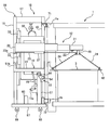
- FIG. 14 is a side view showing another embodiment of a polishing table exchange device (component replacement device) 10 which is a jig for exchanging the polishing table 3
- FIG. 15 is a perspective view of the polishing table exchange device 10. It is.
- the polishing table exchanging device 10 includes a vertical frame 85 extending in the vertical direction, a movable frame 87 movable up and down along the vertical frame 85, and a connecting bracket (connecting member) for connecting the polishing device 1 and the movable frame 87. ) 90, a crane 100 that can move up and down along the vertical frame 85, and a base frame 99 fixed to the lower portion of the vertical frame 85.
- Handles 88 and 89 are fixed to the vertical frame 85 and the movable frame 87, respectively.
- the crane 100 is located below the movable frame 87.
- the connection bracket 90 is a metal bracket having an L-shaped cross section, and is fixed to the movable frame 87 by screws 92. When these screws 92 are removed, the connection bracket 90 can be removed from the movable frame 87.
- a guide rail 95 extending in the vertical direction is fixed to the vertical frame 85.
- the movable frame 87 and the crane 100 are respectively fixed to two linear guides 96 attached to the guide rail 95 so as to be movable up and down.
- the movable frame 87 and the crane 100 are moved along the vertical frame 85 together with these linear guides 96. It can move in the vertical direction.
- the movable frame 87 and the crane 100 can move up and down independently of each other.
- the crane 100 includes a turning shaft 101 extending in the vertical direction and a rail 102 that can turn horizontally around the turning shaft 101. Further, the crane 100 includes a trolley (movable pulley) 104 that can move on the rail 102 in the longitudinal direction of the rail 102, a shaft holding portion 105 that holds the turning shaft 101, and a block 106 to which the shaft holding portion 105 is fixed. And a connecting frame 107 fixed to the block 106. The linear guide 96 described above is fixed to the block 106.
- the polishing table 3 that is a component of the polishing apparatus 1 is suspended from the trolley 104.
- the rail 102 and the movable frame 87 extend horizontally from the vertical frame 85.
- a frame stopper 112 is attached to the upper surface of the block 106.
- the frame stopper 112 has a function of restricting the downward movement of the movable frame 87.
- the dead weight of the movable frame 87 is supported by the crane 100 through the frame stopper 112.
- the frame stopper 112 may be attached to the movable frame 87.
- a crane stopper 114 is attached to the upper surface of the base frame 99.
- the crane stopper 114 has a function of restricting the downward movement of the crane 100.
- the crane stopper 114 may be attached to the crane 100.
- the polishing table exchange device 10 further includes a winch 120 and a chain 121.
- the winch 120 is connected to a horizontal portion 85 a extending from the upper end of the vertical frame 85, and the chain 121 is connected to the connection frame 107 of the crane 100.
- the winch 120 winds up the chain 121 the crane 100 and the movable frame 87 rise together.
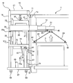
- 16 and 17 are views showing a state where the crane 100 and the movable frame 87 are raised.
- the movable frame 87 is supported by the crane 100 via the frame stopper 112. Therefore, when the winch 120 winds up the chain 121, the crane 100 rises, and the movable frame 87 rises as the crane 100 moves upward. Therefore, the crane 100 and the movable frame 87 are raised together.
- connection bracket (connection member) 90 is fixed to the movable frame 87 in advance.
- the connecting bracket 90 is lifted together with the movable frame 87 and the crane 100 by the winch 120 and the chain 121. Therefore, a dedicated device for raising the connection bracket 90 is not necessary.
- the crane 100 and the movable frame 87 are lowered by its own weight.
- the crane 100 and the movable frame 87 can be lowered until the crane 100 contacts the crane stopper 114. That is, the position where the crane 100 contacts the crane stopper 114 is the lowest position of the crane 100 and the movable frame 87. 14 and 15 show the lowest positions of the crane 100 and the movable frame 87. 16 and 17 show the raised positions of the crane 100 and the movable frame 87.
- the vertical movement of the crane 100 and the movable frame 87 is guided in the vertical direction by the guide rail 95 and the linear guide 96.
- the lifting device that lifts and lowers the crane 100 and the movable frame 87 along the vertical frame 85 includes the winch 120 and the chain 121.
- a plurality of casters 125 as a moving mechanism are fixed to the base frame 99. With these casters 125, the polishing table exchange device 10 itself can be moved to a desired location. By lowering the movable frame 87 and the crane 100, the center of gravity of the entire polishing table exchange device 10 can be lowered. Therefore, the possibility of falling when the polishing table changer 10 is moved is reduced, and the width of the polishing table changer 10 itself can be designed to be small. Therefore, there are effects such as reduction of member cost, reduction of transportation cost, and reduction of storage space. Further, even when the passage width in the factory is limited, the polishing table exchange device 10 can be smoothly moved through the passage.
- the polishing table exchange device 10 is moved to the side of the polishing device 1.
- the chain 121 is wound up by the winch 120, and the crane 100 and the movable frame 87 are raised until the connection bracket 90 is positioned at the same height as the upper frame 1 a of the polishing apparatus 1.
- the connecting bracket 90 is fixed to the upper frame 1a of the polishing apparatus 1 with bolts 130.
- the base frame 99 is fixed to the lower frame 1b of the polishing apparatus 1 with bolts (not shown).
- the winch 120 unwinds the chain 121 and lowers the crane 100 slightly.
- the movable frame 87 is fixed to the upper frame 1a of the polishing apparatus 1 via the connection bracket 90, the movable frame 87 does not descend.
- the polishing table 3 is connected to the trolley 104 of the crane 100 with a belt 128.
- a chain or a wire may be used.
- a suspension bracket 129 is attached to the polishing table 3, and the belt 128 is connected to the polishing table 3 via these suspension brackets 129.
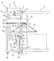
- the chain 121 is wound up by the winch 120, the crane 100 is raised, and the polishing table 3 is pulled up.
- the rail 102 of the crane 100 is turned around the turning shaft 101, and the polishing table 3 is taken out from the polishing apparatus 1.
- the crane 100 is further lowered, and the polishing table 3 is placed on a table carrier (not shown) connected to the polishing table changer 10.
- the belt 128 is removed from the trolley 104 and the suspension bracket 129, whereby the removal operation of the polishing table 3 is completed.
- the chain 121 is wound up by the winch 120 and the crane 100 is raised until the frame stopper 112 contacts the movable frame 87.
- the bolt 130 is removed, and the connection bracket 90 is separated from the upper frame 1a.
- a bolt (not shown) is removed, and the base frame 99 is separated from the lower frame 1b.
- the chain 121 is unwound from the winch 120 and the movable frame 87 and the crane 100 are lowered integrally until the crane 100 contacts the crane stopper 114.
- the center of gravity of the entire polishing table exchange device 10 can be lowered.
- the polishing table exchanging apparatus 10 is an apparatus for exchanging a polishing table that is a component of a semiconductor device manufacturing apparatus, but the present invention is not limited to the above-described embodiment.
- the present invention can be applied to a component replacement device for replacing the polishing head 4 shown in FIG. 1, and further, a component for replacing replacement components of a semiconductor device manufacturing apparatus other than the polishing device. It can also be applied to an exchange device.
- the present invention is applicable to an apparatus for exchanging component parts of a semiconductor device manufacturing apparatus represented by a polishing apparatus for polishing a substrate such as a wafer.
Landscapes
- Engineering & Computer Science (AREA)
- Mechanical Engineering (AREA)
- Finish Polishing, Edge Sharpening, And Grinding By Specific Grinding Devices (AREA)
- Mechanical Treatment Of Semiconductor (AREA)
Abstract
Description
また、本発明は、ウェーハなどの基板を研磨する研磨装置に代表される半導体デバイス製造装置の構成部品を交換するための装置に関する。
また、本発明は、重心が低く、しかも半導体デバイス製造装置に連結するための連結ブラケットを持ち上げるための専用装置を不要とすることができる構成部品交換装置を提供することを目的とする。
好ましい態様は、前記研磨装置に連結される連結部をさらに備えたことを特徴とする。
好ましい態様は、前記クレーンは、水平方向に伸縮自在なリフトアームと、前記リフトアームの先端に取付けられた、前記研磨テーブルを支持するテーブル支持具と、前記リフトアームを上下動させる上下動装置とを備えていることを特徴とする。
好ましい態様は、前記縦フレームの下部に固定された基部フレームと、前記基部フレームと前記クレーンとの間に設けられ、前記クレーンの下方への移動を制限するクレーンストッパとをさらに備えたことを特徴とする。
好ましい態様は、前記クレーンは、鉛直方向に延びる旋回軸と、前記旋回軸を中心として水平に旋回可能なレールと、前記レール上を該レールの長手方向に移動可能な移動式滑車とを備えたことを特徴とする。
好ましい態様は、前記連結部材は、ねじによって前記可動フレームに取り外し可能に固定されていることを特徴とする。
2 研磨パッド
3 研磨テーブル
4 研磨ヘッド
5 研磨液供給ノズル
6 テーブルモータ
7 ヘッドシャフト
10 研磨テーブル交換装置
12 クレーン
14 テーブル台
15 パワージャッキ(テーブル台傾動機構)
16 鉛直フレーム
17 水平フレーム
18 筐体
21 リフトアーム
22 取っ手
23 アームロック機構
24 チェーン(テーブル支持具)
26 アームホルダー
27 ブラケット
30 ウインチ(上下動装置)
33 リニアガイド
41 第1吊りブラケット
42 第2吊りブラケット
44,45,46 連結リング(アイボルト)
48 取付部
51 サポートアーム
51a テーブル載置面
51b 爪
52 連結アーム
54 アーム軸
57 サポートフレーム
61 係止部材
64 アームストッパ(上側アームストッパ)
65 アームストッパ(下側アームストッパ)
67 基部フレーム
69 ローラー
71,72 連結部
75 ベルト
85 縦フレーム
87 可動フレーム
88,89 取っ手
90 連結ブラケット(連結部材)
92 ねじ
95 ガイドレール
96 リニアガイド
99 基部フレーム
100 クレーン
101 旋回軸
102 レール
104 トロリー(移動式滑車)
105 軸保持部
106 ブロック
107 連結フレーム
112 フレームストッパ
114 クレーンストッパ
120 ウインチ
121 チェーン
128 ベルト
129 吊りブラケット
Claims (10)
- 研磨テーブルを研磨装置から取り出すための研磨テーブル交換装置であって、
前記研磨テーブルを鉛直方向および水平方向に移動させるクレーンと、
前記研磨テーブルが載置されるテーブル台と、
前記テーブル台を傾けるテーブル台傾動機構とを備えたことを特徴とする研磨テーブル交換装置。 - 前記研磨テーブル交換装置全体を移動可能とする移動機構をさらに備えたことを特徴とする請求項1に記載の研磨テーブル交換装置。
- 前記研磨装置に連結される連結部をさらに備えたことを特徴とする請求項1または2に記載の研磨テーブル交換装置。
- 前記クレーンは、水平方向に伸縮自在なリフトアームと、前記リフトアームの先端に取付けられた、前記研磨テーブルを支持するテーブル支持具と、前記リフトアームを上下動させる上下動装置とを備えていることを特徴とする請求項1乃至3のいずれか一項に記載の研磨テーブル交換装置。
- 研磨テーブルを上昇させ、
前記上昇された研磨テーブルを水平方向に移動させて前記研磨テーブルを研磨装置から取り出し、
前記研磨テーブルをテーブル台に置き、
前記テーブル台を前記研磨テーブルとともに傾斜させることを特徴とする研磨テーブルの交換方法。 - 半導体デバイス製造装置の構成部品の交換に使用される構成部品交換装置であって、
鉛直方向に延びる縦フレームと、
前記縦フレームに沿って上下動可能な可動フレームと、
前記可動フレームに固定され、前記半導体デバイス製造装置と前記可動フレームとを連結するための連結部材と、
前記可動フレームの下方に位置し、前記縦フレームに沿って上下動可能なクレーンと、
前記クレーンおよび前記可動フレームを前記縦フレームに沿って昇降させる昇降装置とを備えたことを特徴とする構成部品交換装置。 - 前記可動フレームと前記クレーンは互いに独立に上下動可能であり、
前記昇降装置は、前記クレーンに連結されており、
前記可動フレームと前記クレーンとの間には、前記可動フレームの下方への移動を制限するフレームストッパが設けられていることを特徴とする請求項6に記載の構成部品交換装置。 - 前記縦フレームの下部に固定された基部フレームと、
前記基部フレームと前記クレーンとの間に設けられ、前記クレーンの下方への移動を制限するクレーンストッパとをさらに備えたことを特徴とする請求項7に記載の構成部品交換装置。 - 前記クレーンは、鉛直方向に延びる旋回軸と、前記旋回軸を中心として水平に旋回可能なレールと、前記レール上を該レールの長手方向に移動可能な移動式滑車とを備えたことを特徴とする請求項6に記載の構成部品交換装置。
- 前記連結部材は、ねじによって前記可動フレームに取り外し可能に固定されていることを特徴とする請求項6に記載の構成部品交換装置。
Priority Applications (4)
| Application Number | Priority Date | Filing Date | Title |
|---|---|---|---|
| KR1020167034760A KR101836342B1 (ko) | 2014-05-14 | 2015-05-11 | 연마 테이블 교환 장치, 연마 테이블의 교환 방법, 및 반도체 디바이스 제조 장치의 구성 부품을 교환하는 장치 |
| SG11201609101SA SG11201609101SA (en) | 2014-05-14 | 2015-05-11 | Polishing table replacement apparatus, polishing table replacement method, and apparatus for replacing a component of semiconductor-device manufacturing machine |
| CN201580024470.4A CN106457511B (zh) | 2014-05-14 | 2015-05-11 | 研磨台更换装置及半导体元件制造装置的构成零件更换装置 |
| US15/309,508 US9908212B2 (en) | 2014-05-14 | 2015-05-11 | Polishing table replacement apparatus, polishing table replacement method, and apparatus for replacing a component of semiconductor-device manufacturing machine |
Applications Claiming Priority (4)
| Application Number | Priority Date | Filing Date | Title |
|---|---|---|---|
| JP2014100384A JP6255303B2 (ja) | 2014-05-14 | 2014-05-14 | 研磨テーブル交換装置および研磨テーブルの取り出し方法 |
| JP2014-100384 | 2014-05-14 | ||
| JP2015-048837 | 2015-03-11 | ||
| JP2015048837A JP6445357B2 (ja) | 2015-03-11 | 2015-03-11 | 半導体デバイス製造装置の構成部品を交換する装置 |
Publications (1)
| Publication Number | Publication Date |
|---|---|
| WO2015174375A1 true WO2015174375A1 (ja) | 2015-11-19 |
Family
ID=54479914
Family Applications (1)
| Application Number | Title | Priority Date | Filing Date |
|---|---|---|---|
| PCT/JP2015/063500 Ceased WO2015174375A1 (ja) | 2014-05-14 | 2015-05-11 | 研磨テーブル交換装置、研磨テーブルの交換方法、および半導体デバイス製造装置の構成部品を交換する装置 |
Country Status (6)
| Country | Link |
|---|---|
| US (1) | US9908212B2 (ja) |
| KR (1) | KR101836342B1 (ja) |
| CN (1) | CN106457511B (ja) |
| SG (2) | SG11201609101SA (ja) |
| TW (1) | TWI630065B (ja) |
| WO (1) | WO2015174375A1 (ja) |
Cited By (1)
| Publication number | Priority date | Publication date | Assignee | Title |
|---|---|---|---|---|
| JP2017168841A (ja) * | 2016-03-15 | 2017-09-21 | インテグレイテッド ダイナミクス エンジニアリング ゲーエムベーハー | メンテナンス機構 |
Families Citing this family (4)
| Publication number | Priority date | Publication date | Assignee | Title |
|---|---|---|---|---|
| JP7074607B2 (ja) * | 2018-08-02 | 2022-05-24 | 株式会社荏原製作所 | 研磨装置用の治具 |
| KR102341340B1 (ko) * | 2020-03-06 | 2021-12-17 | 에스케이실트론 주식회사 | 패드 드레서 로딩 장치 |
| CN111230797B (zh) * | 2020-04-03 | 2023-05-16 | 山东建筑大学 | 大型链条更换平台装置 |
| CN117963755A (zh) * | 2024-02-06 | 2024-05-03 | 北京北方华创微电子装备有限公司 | 起吊装置及半导体工艺设备 |
Citations (7)
| Publication number | Priority date | Publication date | Assignee | Title |
|---|---|---|---|---|
| JPS5676685U (ja) * | 1979-11-19 | 1981-06-22 | ||
| JPS6067071A (ja) * | 1983-09-22 | 1985-04-17 | Fujitsu Ltd | 半導体ウェハの両面研磨方法 |
| JPS60141463A (ja) * | 1983-12-29 | 1985-07-26 | Hikari Energ Oyo Kenkyusho:Kk | 研磨用部品 |
| JPH10249722A (ja) * | 1997-03-10 | 1998-09-22 | Super Silicon Kenkyusho:Kk | コラムを独立させた研磨装置 |
| JP2000141205A (ja) * | 1998-11-10 | 2000-05-23 | Tokyo Seimitsu Co Ltd | ウェーハ研磨装置及び研磨定盤調整装置 |
| JP2001341068A (ja) * | 2000-06-02 | 2001-12-11 | Hamai Co Ltd | 平面研磨盤の上定盤移動装置 |
| JP2002211405A (ja) * | 2001-01-18 | 2002-07-31 | Mitsubishi Electric Building Techno Service Co Ltd | 吊上げ運搬装置 |
Family Cites Families (13)
| Publication number | Priority date | Publication date | Assignee | Title |
|---|---|---|---|---|
| US3813825A (en) * | 1969-09-30 | 1974-06-04 | Alliance Tool And Die Corp | Polishing machine or the like with a removable platen |
| JPS5676685A (en) | 1979-11-28 | 1981-06-24 | Nippon Telegr & Teleph Corp <Ntt> | Transmission system for binary facsimile signal |
| CN1010927B (zh) * | 1984-12-19 | 1990-12-26 | 洛迦诺电子工业股份有限公司 | 带有固定工作台和可降电解液工作容器的电火花加工机床 |
| US4928435A (en) * | 1985-05-21 | 1990-05-29 | Matsushita Electric Industrial Co., Ltd. | Apparatus for working curved surfaces on a workpiece |
| CN2417156Y (zh) * | 2000-05-01 | 2001-01-31 | 丁桂秋 | 折叠式起重机 |
| US7105446B2 (en) * | 2003-09-04 | 2006-09-12 | Taiwan Semiconductor Manufacturing Co., Ltd. | Apparatus for pre-conditioning CMP polishing pad |
| CN101020536A (zh) * | 2007-03-12 | 2007-08-22 | 江苏天奇物流系统工程股份有限公司 | 轮胎翻转机构 |
| JP5422143B2 (ja) * | 2008-06-04 | 2014-02-19 | 株式会社荏原製作所 | 基板把持機構 |
| TWM404079U (en) * | 2010-12-13 | 2011-05-21 | China Steel Corp | Y-axis mounting/dismounting device for work roll and back-up roll grinding machine |
| CN102672405B (zh) * | 2012-05-09 | 2015-08-05 | 中联重科股份有限公司 | 工件变位机和工件的变位加工方法、变位加工系统 |
| CN103624674A (zh) * | 2012-08-27 | 2014-03-12 | 深圳富泰宏精密工业有限公司 | 研磨机升降机构及应用该升降机构的研磨机 |
| TWM445472U (zh) * | 2012-09-12 | 2013-01-21 | China Steel Corp | 磨床吊架維修輔助裝置 |
| TWM459066U (zh) * | 2013-02-20 | 2013-08-11 | China Steel Corp | 磨床頭座皮帶拆裝機構 |
-
2015
- 2015-05-11 KR KR1020167034760A patent/KR101836342B1/ko not_active Expired - Fee Related
- 2015-05-11 CN CN201580024470.4A patent/CN106457511B/zh active Active
- 2015-05-11 US US15/309,508 patent/US9908212B2/en not_active Expired - Fee Related
- 2015-05-11 SG SG11201609101SA patent/SG11201609101SA/en unknown
- 2015-05-11 TW TW104114870A patent/TWI630065B/zh active
- 2015-05-11 WO PCT/JP2015/063500 patent/WO2015174375A1/ja not_active Ceased
- 2015-05-11 SG SG10201704000QA patent/SG10201704000QA/en unknown
Patent Citations (7)
| Publication number | Priority date | Publication date | Assignee | Title |
|---|---|---|---|---|
| JPS5676685U (ja) * | 1979-11-19 | 1981-06-22 | ||
| JPS6067071A (ja) * | 1983-09-22 | 1985-04-17 | Fujitsu Ltd | 半導体ウェハの両面研磨方法 |
| JPS60141463A (ja) * | 1983-12-29 | 1985-07-26 | Hikari Energ Oyo Kenkyusho:Kk | 研磨用部品 |
| JPH10249722A (ja) * | 1997-03-10 | 1998-09-22 | Super Silicon Kenkyusho:Kk | コラムを独立させた研磨装置 |
| JP2000141205A (ja) * | 1998-11-10 | 2000-05-23 | Tokyo Seimitsu Co Ltd | ウェーハ研磨装置及び研磨定盤調整装置 |
| JP2001341068A (ja) * | 2000-06-02 | 2001-12-11 | Hamai Co Ltd | 平面研磨盤の上定盤移動装置 |
| JP2002211405A (ja) * | 2001-01-18 | 2002-07-31 | Mitsubishi Electric Building Techno Service Co Ltd | 吊上げ運搬装置 |
Cited By (3)
| Publication number | Priority date | Publication date | Assignee | Title |
|---|---|---|---|---|
| JP2017168841A (ja) * | 2016-03-15 | 2017-09-21 | インテグレイテッド ダイナミクス エンジニアリング ゲーエムベーハー | メンテナンス機構 |
| KR20170107406A (ko) * | 2016-03-15 | 2017-09-25 | 인티그레이티드 다이나믹스 엔지니어링 게엠베하 | 유지보수 장치 |
| KR102388699B1 (ko) | 2016-03-15 | 2022-04-20 | 인티그레이티드 다이나믹스 엔지니어링 게엠베하 | 유지보수 장치 |
Also Published As
| Publication number | Publication date |
|---|---|
| KR20170005091A (ko) | 2017-01-11 |
| SG10201704000QA (en) | 2017-06-29 |
| KR101836342B1 (ko) | 2018-04-19 |
| US9908212B2 (en) | 2018-03-06 |
| TW201605575A (zh) | 2016-02-16 |
| CN106457511A (zh) | 2017-02-22 |
| SG11201609101SA (en) | 2016-12-29 |
| US20170151649A1 (en) | 2017-06-01 |
| CN106457511B (zh) | 2019-12-13 |
| TWI630065B (zh) | 2018-07-21 |
Similar Documents
| Publication | Publication Date | Title |
|---|---|---|
| WO2015174375A1 (ja) | 研磨テーブル交換装置、研磨テーブルの交換方法、および半導体デバイス製造装置の構成部品を交換する装置 | |
| JP6093741B2 (ja) | 研磨装置及びウェーハの研磨方法 | |
| WO2015027617A1 (zh) | 一种玻璃基板的取放装置 | |
| JP6178774B2 (ja) | 定盤運搬台車 | |
| JP6255303B2 (ja) | 研磨テーブル交換装置および研磨テーブルの取り出し方法 | |
| JP6445357B2 (ja) | 半導体デバイス製造装置の構成部品を交換する装置 | |
| CN222449800U (zh) | 一种具有加压提拉机构的研磨夹具 | |
| JP5706228B2 (ja) | エレベータ機器の点検用作業台 | |
| JP2019084611A (ja) | 研磨装置 | |
| JP5956774B2 (ja) | 弁着脱装置 | |
| KR101322959B1 (ko) | 패드 오버헤드 부착용 리프트 장치 | |
| TW201707839A (zh) | 垂直式修補機及其修補方法 | |
| JPH0919862A (ja) | ポリッシング装置のロード・アンロードユニット | |
| CN215147877U (zh) | 一种表盘加工用多工位磨光机 | |
| JP7232136B2 (ja) | 加工装置 | |
| CN222359273U (zh) | 一种用于塞棒的快速定位装置 | |
| CN221987444U (zh) | 一种集装箱后框生产线 | |
| CN107104068B (zh) | 用于去除晶圆表面凸起的装置 | |
| CN116692484B (zh) | 一种牵引辊保护装置 | |
| JP2002110548A (ja) | 反応炉チャンバの着脱方法 | |
| JP7746217B2 (ja) | 処理システムおよびパッド搬送装置 | |
| JP7106067B2 (ja) | 片面研磨装置 | |
| JP2012152832A (ja) | 治具 | |
| CN121468397A (zh) | 一种可自动提升翻转的研磨夹具 | |
| KR20070023215A (ko) | 리프트 장치 및 이를 이용하여 반도체부품을 장착 및탈착하는 방법들 |
Legal Events
| Date | Code | Title | Description |
|---|---|---|---|
| 121 | Ep: the epo has been informed by wipo that ep was designated in this application |
Ref document number: 15792531 Country of ref document: EP Kind code of ref document: A1 |
|
| WWE | Wipo information: entry into national phase |
Ref document number: 15309508 Country of ref document: US |
|
| NENP | Non-entry into the national phase |
Ref country code: DE |
|
| ENP | Entry into the national phase |
Ref document number: 20167034760 Country of ref document: KR Kind code of ref document: A |
|
| 122 | Ep: pct application non-entry in european phase |
Ref document number: 15792531 Country of ref document: EP Kind code of ref document: A1 |