WO2015170591A1 - 反射器切替え装置 - Google Patents
反射器切替え装置 Download PDFInfo
- Publication number
- WO2015170591A1 WO2015170591A1 PCT/JP2015/062194 JP2015062194W WO2015170591A1 WO 2015170591 A1 WO2015170591 A1 WO 2015170591A1 JP 2015062194 W JP2015062194 W JP 2015062194W WO 2015170591 A1 WO2015170591 A1 WO 2015170591A1
- Authority
- WO
- WIPO (PCT)
- Prior art keywords
- reflector
- exposed state
- switching device
- rotation shaft
- plate
- Prior art date
- Legal status (The legal status is an assumption and is not a legal conclusion. Google has not performed a legal analysis and makes no representation as to the accuracy of the status listed.)
- Ceased
Links
Images





Classifications
-
- B—PERFORMING OPERATIONS; TRANSPORTING
- B60—VEHICLES IN GENERAL
- B60Q—ARRANGEMENT OF SIGNALLING OR LIGHTING DEVICES, THE MOUNTING OR SUPPORTING THEREOF OR CIRCUITS THEREFOR, FOR VEHICLES IN GENERAL
- B60Q1/00—Arrangement of optical signalling or lighting devices, the mounting or supporting thereof or circuits therefor
- B60Q1/26—Arrangement of optical signalling or lighting devices, the mounting or supporting thereof or circuits therefor the devices being primarily intended to indicate the vehicle, or parts thereof, or to give signals, to other traffic
- B60Q1/2692—Arrangement of optical signalling or lighting devices, the mounting or supporting thereof or circuits therefor the devices being primarily intended to indicate the vehicle, or parts thereof, or to give signals, to other traffic retractable lights
-
- B—PERFORMING OPERATIONS; TRANSPORTING
- B60—VEHICLES IN GENERAL
- B60Q—ARRANGEMENT OF SIGNALLING OR LIGHTING DEVICES, THE MOUNTING OR SUPPORTING THEREOF OR CIRCUITS THEREFOR, FOR VEHICLES IN GENERAL
- B60Q1/00—Arrangement of optical signalling or lighting devices, the mounting or supporting thereof or circuits therefor
- B60Q1/26—Arrangement of optical signalling or lighting devices, the mounting or supporting thereof or circuits therefor the devices being primarily intended to indicate the vehicle, or parts thereof, or to give signals, to other traffic
- B60Q1/30—Arrangement of optical signalling or lighting devices, the mounting or supporting thereof or circuits therefor the devices being primarily intended to indicate the vehicle, or parts thereof, or to give signals, to other traffic for indicating rear of vehicle, e.g. by means of reflecting surfaces
-
- B—PERFORMING OPERATIONS; TRANSPORTING
- B60—VEHICLES IN GENERAL
- B60Q—ARRANGEMENT OF SIGNALLING OR LIGHTING DEVICES, THE MOUNTING OR SUPPORTING THEREOF OR CIRCUITS THEREFOR, FOR VEHICLES IN GENERAL
- B60Q1/00—Arrangement of optical signalling or lighting devices, the mounting or supporting thereof or circuits therefor
- B60Q1/26—Arrangement of optical signalling or lighting devices, the mounting or supporting thereof or circuits therefor the devices being primarily intended to indicate the vehicle, or parts thereof, or to give signals, to other traffic
- B60Q1/30—Arrangement of optical signalling or lighting devices, the mounting or supporting thereof or circuits therefor the devices being primarily intended to indicate the vehicle, or parts thereof, or to give signals, to other traffic for indicating rear of vehicle, e.g. by means of reflecting surfaces
- B60Q1/301—Arrangement of optical signalling or lighting devices, the mounting or supporting thereof or circuits therefor the devices being primarily intended to indicate the vehicle, or parts thereof, or to give signals, to other traffic for indicating rear of vehicle, e.g. by means of reflecting surfaces by means of surfaces, e.g. metal plate, reflecting the light of an external light source
-
- B—PERFORMING OPERATIONS; TRANSPORTING
- B60—VEHICLES IN GENERAL
- B60Y—INDEXING SCHEME RELATING TO ASPECTS CROSS-CUTTING VEHICLE TECHNOLOGY
- B60Y2400/00—Special features of vehicle units
- B60Y2400/30—Sensors
Definitions
- the present invention relates to a reflector switching device.
- a contour display reflector must be provided on the outer periphery of the rear surface of the loading platform.
- the contour display reflector is for displaying the contour of the bed, and the red reflector and the white reflector must be installed alternately.
- Japan it is possible to mount a white reflector on the front surface of the platform, a white reflector or a yellow reflector on the side, and a red reflector or a yellow reflector on the rear surface.
- the installation of the installation of reflectors is not mandatory, but reflectors other than specified colors can not be installed.
- Patent Document 1 As a mechanism for switching between the state in which the reflector is exposed and the state in which the reflector is hidden, there is one disclosed in Patent Document 1.
- a rotating body provided with a reflector is provided at the bottom side opening of the rear swing. At the time of closing the rear swing, the face of the rotating body other than the reflector is exposed from the opening.
- the rotating body is rotated relative to the rear pivot so that the reflector is exposed from the opening.
- Patent Document 1 Since the switching mechanism of Patent Document 1 switches between the exposed state and the hidden state of the reflector by opening and closing the rear part, applying it to a vehicle that carries out mutual transportation between Japan and a foreign country could not. Besides, there was no switching mechanism applicable to vehicles carrying each other.
- this invention makes it a subject to provide the reflector switching apparatus applicable to the vehicle which carries out mutual transport of Japan and a foreign country.
- the invention according to claim 1 for solving the above-mentioned problems is a reflector switching device for switching an exposed state and a non-exposed state of a reflector provided on a wall surface of a transport vehicle, wherein a rotation axis along the wall surface And a plate attached to the rotating shaft, and rotating the plate along with the rotating shaft to switch between an exposed state in which the reflector is exposed and a non-exposed state in which the reflector is hidden. And a reflector switching device.
- the present invention can be applied to a vehicle performing mutual transportation between Japan and foreign countries.
- the reflector is fixed to the wall surface, the plate member covers the reflector in the non-exposed state, and the plate member in the exposed state is the rotating shaft. It is characterized by being located in the other side of the said reflector on both sides. According to such a configuration, it is possible to switch between the exposed state and the non-exposed state of the reflector with a simple configuration and a simple operation.
- the reflector is fixed to one surface of the plate material, and the reflector faces the wall surface in the non-exposed state, and the plate material in the exposed state The other side of the wall faces the wall surface. According to such a configuration, it is possible to switch between the exposed state and the non-exposed state of the reflector with a simple configuration and a simple operation.
- the rotating shaft is provided along the outer peripheral edge of the door on the rear surface of the transport vehicle, and the rotating shafts orthogonal to each other are transmitted through the transmission means for synchronously transmitting the rotation. It is characterized by being connected. According to such a configuration, since the plurality of rotating shafts are rotated only by rotating one rotating shaft, it is possible to omit the time and effort of the switching operation. Furthermore, since each rotation axis rotates synchronously, the exposure state or non-exposure state of the reflector on each rotation axis can be aligned.
- the invention according to claim 5 is characterized by further comprising stopper means for stopping the rotation of the rotary shaft at a predetermined position. According to such a configuration, the rotating shaft can be reliably held in the exposed state or the non-exposed state.
- the invention according to claim 6 comprises a sensor for detecting whether the reflector is in the exposed state or the non-exposed state, and display means for displaying the information acquired by the sensor on the driver's seat. Furthermore, it is characterized by having. According to such a configuration, the exposed state of the reflector can be confirmed even during operation.
- the invention according to claim 7 further comprises an actuator for rotating the rotation shaft. According to such a configuration, the exposed state and the non-exposed state of the reflector can be automatically switched easily.
- the actuator comprises an extension and contraction mechanism, a gear mechanism, a power source, and a control device, and the gear mechanism rotates the rotation shaft in accordance with the operation of the extension and contraction mechanism,
- the control device is characterized by being operable from the driver's seat. According to such a configuration, the switching operation is easy, and it can be confirmed from the driver's seat whether it is in the exposed state or the non-exposed state.
- the reflector switching device according to the present invention can be applied to vehicles that mutually transport Japan and foreign countries.
- FIG. 1 It is a figure showing a stopper means, and (a) is a back elevation, (b) is a sectional view cut in the direction orthogonal to the axial center of a rotating shaft, (c) is a back elevation showing a receiving member. It is the figure which showed the rear surface of the loading platform which installed the reflector switching apparatus (exposure state) which concerns on 2nd embodiment of this invention. It is the figure which showed the rear surface of the loading platform which installed the reflector switching apparatus (non-exposed state) which concerns on 2nd embodiment of this invention. It is the figure which showed the rear surface of the loading platform which installed the reflector switching apparatus (exposure state) which concerns on the modification of 1st embodiment of this invention.
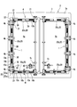
- the reflector switching device 1 is a reflector provided on the wall surface of the transport vehicle 2 (in the present embodiment, the white reflector 10 a of the white reflector 10 a and the red reflector 10 b And the non-exposure state.
- the plurality of reflectors 10 a and 10 b are provided on the door 4 on the rear surface (wall surface) of the bed 3 of the transport vehicle 2.
- the door 4 of this embodiment has a double-opening structure, and includes two door bodies 4a.
- the door main body 4a is fixed to the end in the width direction of the rear body 3a of the transport vehicle 2 so as to be capable of opening and closing via a plurality of hinge members 4b, 4b,.
- a lock mechanism 4c for fixing the door main body 4a to the rear surface body 3a in a closed state is provided on the front end side of the door main body 4a.
- the reflectors 10 a and 10 b are attached to the outer peripheral edge of the door 4.
- the reflectors 10a and 10b are configured by rectangular retroreflectors.
- One reflector 10a is a white reflector
- the other reflector 10b is a red reflector.
- the “white reflector 10 a” and the “red reflector 10 b” will be referred to.
- the white reflectors 10 a and the red reflectors 10 b are alternately arranged along the outer peripheral edge of the door 4.
- white reflectors 10a are disposed at the four corners of the rear surface.
- the reflectors 10a and 10b are not provided at the portion where the hinge member 4b and the lock mechanism 4c are located at the outer peripheral edge portion of the door 4.
- the reflector switching device 1 is provided in each of the two door bodies 4a and 4a.
- Each reflector switching device 1 includes a rotating shaft 20, a plate 30, a stopper 40, a sensor 50, and a display (not shown).
- the rotary shaft 20 is attached to the lower side, the outer side, and the upper side of the door body 4 a. That is, the lower rotation shaft 20a provided on the lower side of the door main body 4a, the side rotation shaft 20b provided on the side near the base end, and the upper rotation provided on the upper side There is an axis 20c.
- the lower rotation shaft 20a is disposed orthogonal to the side rotation shaft 20b at the lower end of the side rotation shaft 20b
- the upper rotation shaft 20c is orthogonal to the side rotation shaft 20b at the upper end of the side rotation shaft 20b.
- the upper rotation shaft 20c is disposed above the lower rotation shaft 20a.
- the lower rotation shaft 20a extends in the horizontal direction above the reflectors 10a and 10b arranged along the lower side of the door body 4a.
- the lower rotation shaft 20a is disposed at a position not overlapping the reflectors 10a and 10b.
- the end of the lower rotation shaft 20a at the center side in the vehicle width direction (the tip end side of the door main body 4a) is rotatably supported by a bearing 21 provided on the surface of the door main body 4a.
- the end of the lower rotation shaft 20a in the vehicle width direction outer side (the base end side of the door main body 4a) is rotatably supported by another bearing 21 provided on the surface of the door main body 4a, and the end protrudes ing.
- a transmission member 22 described later is provided at the end of the protruding lower rotary shaft 20a.
- the side rotation shaft 20b extends in the vertical direction inside the reflectors 10a and 10b aligned along the side of the door body 4a.
- the side rotation shaft 20b is disposed at a position not overlapping the reflectors 10a and 10b.
- the side rotation shaft 20b is disposed orthogonal to the lower rotation shaft 20a.
- the upper and lower end portions of the side rotation shaft 20b are rotatably supported by bearings 21, 21 provided on the surface of the door main body 4a, and the end portions respectively protrude.
- Transmission members 22 are respectively provided at upper and lower end portions of the protruding side rotation shaft 20b.
- the rotary shaft 20b protrudes downward from the lower transmission member 22, and the rotary shaft 20b protrudes upward from the upper side delivery member 22 (only the lower side is shown in FIG. 3).
- the front end of the rotating shaft 20b extending up and down is rotatably supported by the bearings 21 and 21, respectively. That is, the side rotation shaft 20b is supported by two bearings at the top and bottom in total, and is stabilized.
- the upper rotation shaft 20c extends in the horizontal direction below the reflectors 10a and 10b arranged along the upper side of the door body 4a.
- the upper rotation shaft 20c is disposed at a position not overlapping the reflectors 10a and 10b.
- the upper rotation shaft 20c is disposed orthogonal to the side rotation shaft 20b.
- An end on the center side in the vehicle width direction of the upper rotation shaft 20c is rotatably supported by a bearing 21 provided on the surface of the door main body 4a.
- the end of the upper rotation shaft 20c on the outer side in the vehicle width direction is rotatably supported by another bearing 21 provided on the surface of the door main body 4a, and the end protrudes.
- a transmission member 22 is provided at the end of the protruding upper rotary shaft 20c.
- the transmission member 22 is a member which transmits rotational force, synchronizing the rotation of adjacent rotational shafts 20 and 20 each other.
- the transmission member 22 includes, for example, a pair of bevel gears (bevel gears) 22a, 22a provided at the tip end portions of the adjacent rotation shafts 20, 20, respectively.
- the lower rotation shaft 20a, the side rotation shaft 20b, and the upper rotation shaft 20c are synchronously rotated by the transmission member 22. That is, when the lower rotation shaft 20a rotates 90 degrees, the side rotation shaft 20b and the upper rotation shaft 20c also rotate 90 degrees.
- the transmission member 22 is not limited to the bevel gear, and may be a universal joint or a power transmission means of a friction system. In consideration of the performance to be synchronized, it is preferable to have a gear rather than the transmission power means of the friction system.
- the plate member 30 extends along the axial direction of the rotation shaft 20 and extends radially outward along the normal direction of the outer peripheral surface. The edge of the plate member 30 is welded to the outer peripheral surface of the rotating shaft 20. When the rotation shaft 20 is half-rotated, the plate member 30 is reversed around the rotation shaft 20.
- the plate members 30 are provided in the same number as the white reflectors 10a, and are welded to the surface of the rotary shaft 20 at a position adjacent to the white reflectors 10a.
- the plate member 30 has a rectangular planar shape slightly larger than the white reflector 10a, and is white when viewed from the rear side when it is located behind the white reflector 10a (in an unexposed state). It is comprised so that the reflector 10a may be covered.
- the plate member 30 In the non-exposed state, the plate member 30 is positioned behind the white reflector 10a to hide the white reflector 10a. In the unexposed state, the white reflector 10a is not visible from the rear.
- the rotating shaft 20 In the exposed state, the rotating shaft 20 is rotated 180 degrees from the non-exposed state, and the plate member 30 is inverted. In the exposed state, the plate member 30 moves to the opposite side across the rotation shaft 20, so the white reflector 10a can be viewed from the rear.
- the reflector switching device 1 of this embodiment switches the exposed state and the non-exposed state of the white reflector 10a provided on the door 4 of the rear surface (wall surface) of the loading platform 3 of the transport vehicle 2
- the color of the reflector to be hidden is not limited to white, and it is possible to hide reflectors of various colors according to the laws of each country (including those other than Japan and China).
- the reflector is not limited to the retroreflector, and of course it may be an electroluminescent or seal type reflector.
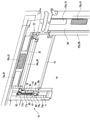
- the stopper means 40 fixes the rotation shaft 20 at the rotation angle in the exposed state and the rotation angle in the non-exposed state. As shown in FIG. 4, the stopper means 40 is provided on the lower rotation shaft 20a. Specifically, the stopper means 40 is provided on the holding lever 41 provided on the lower rotation shaft 20a.
- the grip lever 41 is provided on the outer peripheral surface of the lower rotation shaft 20 a.
- the gripping lever 41 extends in a direction orthogonal to the lower rotation shaft 20a.
- the grip lever 41 includes a support portion 42 and a grip portion 43 extending from the support portion 42.
- the support portion 42 is configured by bending a metal plate into a gate shape, and includes a pair of leg portions and a connection portion.
- the pair of leg portions is disposed at an interval in the axial direction of the lower rotation shaft 20a.
- the connecting portion connects the upper ends of the pair of legs.
- the gripping portion 43 is made of a metal plate and is welded to the connecting portion of the support portion 42.
- the gripping portion 43 extends from the support portion 42 along a virtual plane passing through the plates 30, 30. Spacers 44 are attached to both sides of the grip 43, respectively.
- the spacer 44 is for preventing the gripping portion 43 from colliding with the surface of the door main body 4a, and is made of an elastic resin.
- the stopper means 40 includes a pin 45 attached to the support portion 42 and a receiving member 46 attached to the surface of the door main body 4a.
- the pin 45 is disposed along the axial length direction of the lower rotation shaft 20 a and is bridged between the pair of legs of the support portion 42.
- the pin 45 is supported by the support portion 42 so as to be movable in the longitudinal direction. Both ends in the axial direction of the pin 45 protrude outside the pair of legs.
- a spring member 47 covering the pin 45 is provided between the legs. The pin 45 is biased by the spring member 47 toward the distal end side (right side in FIG. 4A).
- the receiving member 46 is formed of an angled member having an L-shaped cross section.
- the receiving member 46 includes an abutting portion that abuts on the surface of the door main body 4 a and a rising portion that rises to the side of the supporting portion 42.
- the receiving member 46 extends in the vertical direction, and is orthogonal to the lower rotation shaft 20a.
- the contact portion of the receiving member 46 is fixed to the door main body 4a.
- the rising portion of the receiving member 46 is disposed on the side of the leg (the tip side of the pin 45).
- Pin holes 48 (see (b) and (c) in FIG. 4) are formed in the rising portion.
- the tip of the pin 45 is inserted into the pin hole 48, and the pin 45 is locked to the receiving member 46.
- the pin holes 48 are provided at both the upper end and the lower end of the rising portion.
- the upper pin hole 48 is formed at the position of the tip of the pin 45 when the plate 30 is in the exposed state.
- the lower pin hole 48 is formed at the position of the tip of the pin 45 when the plate 30 is in the non-exposed state.
- a notch 49 is provided at a vertically middle portion of the rising portion.
- the lower rotation shaft 20 a passes through the notch 49.
- the sensor 50 detects whether the white reflector 10 a is in an exposed state or a non-exposed state.
- the sensor 50 is configured by an indicator switch, and is provided on the wall surface of the cargo bed 3 below the lower rotation shaft 20a.
- the sensor 50 is provided at a position at which a rod 51 provided at the tip of the grip 43 of the grip lever 41 abuts.
- the rod 51 extends in a direction perpendicular to the surface of the grip 43 and protrudes in the thickness direction of the grip 43.
- the rod 51 protrudes forward of the vehicle when the grip lever 41 is positioned below the lower rotation shaft 20a, and its tip contacts the sensor 50 to push the sensor 50 (the phantom line in the lower part of FIG. See part).
- the sensor 50 detects that the white reflector 10 a is in the exposed state or the non-exposed state by detecting that it is pressed by the tip of the rod 51. Specifically, when it is detected that the sensor 50 is pressed by the rod 51, the plate member 30 covers the white reflector 10a below the lower rotation shaft 20a, and the white reflector 10a is not exposed. It is in the state. When the sensor 50 is not pressed by the rod 51, the plate 30 is inverted above the lower rotation shaft 20a, and the white reflector 10a is in the exposed state.
- the kind of sensor 50 is not limited to the said structure, A various sensor is applicable suitably.
- the display means (not shown) is electrically connected to the sensor 50.
- the display means is composed of a lamp that can be viewed from the driver's seat, and for example, when the sensor 50 is pressed (when the indicator switch is turned on), the lamp is lit. That is, when the lamp is lit, the white reflector 10a is in the non-exposed state, and when the lamp is not lit, the driver can determine that the white reflector 10a is in the exposed state.
- the reflector switching device 1 configured as above, when the transport vehicle 2 travels in Japan, as shown in FIG.
- the lower pin hole 48 of the receiving member 46 is locked.
- the lower rotation shaft 20a, the side rotation shaft 20b, and the upper rotation shaft 20c which are respectively connected via the transmission member 22, rotate in synchronization with each other.
- the plate 30 of the lower rotating shaft 20a rotates downward to cover the white reflector 10a
- the plate 30 of the side rotating shaft 20b rotates outward to cover the white reflector 10a.
- the plate 30 of the upper rotation shaft 20c rotates upward to cover the white reflector 10a.
- the rotary shaft 20 since the rotary shaft 20 is locked by the stopper means 40, the rotary shaft 20 can be reliably held in the non-exposed state without rotating even if vibration or the like during running is applied. .
- the sensor 50 detects that it is in the non-exposed state. Then, since the display means is turned on at the driver's seat, the driver can confirm that the white reflector 10a is in the non-exposed state without having to go to the rear of the transport vehicle 2 for visual observation. In addition, it can be confirmed that it is in the non-exposed state even during operation.
- the entire rotation shaft 20 can be rotated simply by moving the holding lever 41 provided on the lower rotation shaft 20a. Can. Therefore, the switching operation of the reflector can be performed at a position where it can be reached, and the operation of rotating the side rotation shaft 20b and the upper rotation shaft 20c is not necessary, so the operation is easy.
- the grip lever 41 is turned upward to lock the pin 45 of the stopper means 40 in the upper pin hole 48 of the receiving member 46.
- the plate 30 of the lower rotation shaft 20a rotates (reverses) upward and leaves the white reflector 10a
- the plate 30 of the side rotation shaft 20b rotates (reverses) inward to move from the white reflector 10a.
- the plate 30 of the upper rotation shaft 20c rotates downward (reverses) and separates from the white reflector 10a.
- the sensor 50 detects that it is not exposed. Then, since the display means is turned off at the driver's seat, the driver can confirm that the white reflector 10a is in the exposed state without having to go to the rear of the transport vehicle 2 for visual observation. In addition, it can be confirmed that it is in the exposed state even during operation.
- the reflector switching device 1 it is possible to switch between the exposed state and the non-exposed state of the white reflector 10 a simply by rotating the rotating shaft 20. This can provide a transport vehicle capable of mutual transportation between Japan and China. Furthermore, it is possible to adapt to foreign laws and regulations other than China by appropriately changing the color and type of the reflector that switches between the exposed state and the unexposed state.
- the reflector switching device 1 is formed by the rotatable rotating shaft 20 and the plate member 30, the structure is simple and can be easily manufactured. Furthermore, since the entire reflector switching device 1 is provided on the door 4, the door 4 can be opened and closed.
- the reflector switching device 1a of the second embodiment will be described with reference to FIGS. 5 and 6.
- the shape of the plate 31 is different from that of the plate 30 of the embodiment.
- the plate member 30 is configured to cover only the white reflector 10a, but in the reflector switching device 1a according to another embodiment, the plate member 31 provided on the rotating shaft 20 is It is configured to cover both the white reflector 10a and the red reflector 10b. That is, the plate member 31 is welded to the rotary shaft 20 at a position adjacent to the white reflector 10a and the red reflector 10b.
- symbol is attached
- both the white reflector 10a and the red reflector 10b are covered and not exposed. It will be possible to run in Japan.
- the reflector 10 is in the exposed state, as shown in FIG. 5, since the plate member 31 is inverted to expose both the white reflector 10a and the red reflector 10b, traveling in China becomes possible. .
- the form for implementing this invention was demonstrated, this invention is not the meaning limited to the said embodiment, A design change is suitably possible in the range which does not deviate from the meaning of this invention.
- the reflector switching apparatus is provided in the rear surface of a loading platform, it is not limited to this.
- the installation position of the reflector switching device may be the side or the front of the carrier.
- the white reflector 10a is provided in the single side
- the white reflector 10a is attached to a surface that can be viewed from the rear when the plate 30 is positioned on the outer peripheral side (see FIG. 7). In this case, the white reflector 10a is not provided on the surface of the door 4, and only the red reflector 10b is provided.
- symbol is attached
- the white reflector 10a when the plate member 30 is on the outer peripheral side, the white reflector 10a is located between the red reflectors 10b and can be viewed from the rear.
- the white reflector 10a when the plate 30 is turned to the inner peripheral side, the white reflector 10a faces the door side, so when viewed from the rear, the white reflector 10a is hidden by the plate 30, and the white reflector 10a becomes unexposed (FIG. 8). reference).
- the exposed state and the non-exposed state of the white reflector 10a can be easily switched by only rotating the rotating shaft 20 and the plate member 30.
- both the white reflector and the red reflector may be attached to one side of a plate 31 having the same shape as the plate 31 in FIGS. 5 and 6. With such a configuration, when the plate is positioned on the outer peripheral side, both the white reflector and the red reflector are exposed, and when the plate is reversed to the inner peripheral side, both the white reflector and the red reflector are becomes unexposed.
- the reflector switching device 1b according to the third embodiment is attached to, for example, a double number acquisition trailer that can travel between two countries with different traffic laws, such as Japan and China. This trailer has two electric signal lines, Japan mode and China mode.
- the reflector 10 is fixed to one surface of the plate 31.
- both the white reflector 10a and the red reflector 10b are provided on each of the three plate members 30 provided on the lower rotation shaft 20a, the side rotation shaft 20b, and the upper rotation shaft 20c. ing.
- the white reflectors 10 a and the red reflectors 10 b are alternately affixed along the longitudinal direction of the plate members 30.
- Each of the reflectors 10 is attached to a surface (one surface) facing rearward when the plate 30 is positioned outside the rotation shaft 20.
- the plate 30 when the plate 30 is positioned on the outer peripheral side of the rotation shaft 20, the other surface of the plate 30 faces the wall surface, while the reflector 10 (white reflector 10a and red reflector 10b) is directed backward. It will be in an exposed state, and it will be in the state which can be seen from the back.
- the reflector 10 faces the wall surface and is not exposed, and can not be viewed from the rear (see FIG. 10).
- the reflector switching device 1b further includes a pair of actuators 70, 70 in addition to the rotating shaft 20, the plate 30, and the display means (not shown).
- the actuators 70 are respectively provided on the left and right door main bodies 4a, 4a.
- the actuator 70 rotates the rotating shaft 20.
- the actuator 70 of the present embodiment rotates the upper rotation shaft 20 c.
- the side rotation shaft 20 b and the lower rotation shaft 20 a also rotate in conjunction with the transmission member 22.
- the actuator 70 includes an expansion and contraction mechanism 71, a gear mechanism 72, a power source (not shown), and a control device 73 (see FIG. 11).
- the expansion and contraction mechanism 71 is provided on the top of the door main body 4a, and is configured of, for example, an air cylinder.
- the extension mechanism 71 is not limited to the air cylinder, and may be another such as a hydraulic cylinder.
- the extension mechanism 71 is provided to extend in the vertical direction on the door main body 4a.
- the expansion and contraction mechanism 71 is accommodated in a recess 60 provided on the surface of the door main body 4a.
- the concave portion 60 is opened rearward and formed in a vertically long shape.
- the telescopic mechanism 71 is accommodated in the lower part of the recess 60.
- the piston rod 74b of the extension and retraction mechanism 71 advances and retracts from the cylinder tube 74a in the vertical direction.
- the expansion and contraction mechanism 71 is connected with an air pipe 76a for supplying actuating air to the piston side air chamber 75a and an air pipe 76b for supplying actuating air to the rod side air chamber 75b.
- Each of the air pipe 76a and the air pipe 76b intervenes a speed controller 85 which controls the flow velocity of the air supplied to the expansion and contraction mechanism 71 at a constant level.
- symbol "76" in FIG.12 and FIG.13 is a cover which covers the air pipe 76a and the air pipe 76b on the door main body 4a.
- the gear mechanism 72 is provided at the upper portion of the door main body 4a, and is configured of, for example, a rack 77a and a pinion 77b.
- the rack 77 a extends in the vertical direction, and is disposed above the recess 60.
- the rack 77 a is attached to the upper end portion of the piston rod 74 b, and moves up and down with the expansion and contraction of the expansion and contraction mechanism 71.
- Guide rollers 83 are provided at both ends in the width direction of the rack 77a. The guide rollers 83 rotate along guide rails 61 provided at both widthwise end portions of the recess 60.
- the pinion 77b meshes with the rack 77a, and rotates as the rack 77a moves up or down.
- the pinion 77 b is attached to an end of the upper rotation shaft 20 c.
- a separate gear may be interposed between the pinion 77 b and the upper rotation shaft 20 c.
- the upper rotation shaft 20c rotates with the pinion 77b.
- a cover (not shown) is provided at the open end of the recess 60.
- the cover body covers the extension mechanism 71, the rack 77a and the pinion 77b.
- the control device 73 includes an electromagnetic switching valve 79 that switches the supply destination of the operating air from the air supply line 78.
- the electromagnetic switching valve 79 can switch three positions: a non-operating position (see (a) in FIG. 11), an extended position (see (b) in FIG. 11), and a retracted position (see (c) in FIG. 11) It has become.
- the electromagnetic switching valve 79 is composed of a double solenoid provided with two solenoids.
- a Japan mode electrical signal line 80a is connected to one solenoid of the electromagnetic switching valve 79, and a Chinese mode electrical signal line 80b is connected to the other solenoid.
- the electromagnetic switching valve 79 is normally in the non-operating position.
- a filter regulator unit 84 is provided in the air supply line 78 so that air can be stably supplied.
- the control device 73 is provided at or near the driver's seat, and can be operated from the driver's seat.
- the control device 73 is provided at the driver's seat with a Japan mode side terminal, a China mode side terminal, and an electrical coupling (connection portion) selectively connected to each of these terminals. Connecting the electrical coupling to the Japan mode side terminal enables the Japan mode electrical signal line 80a, and connecting the electrical coupling to the Chinese mode side terminal enables the Chinese mode electrical signal line 80b.
- the procedure for switching between the exposed state and the non-exposed state will be described below.
- an electric coupling (not shown) is connected to the Japanese mode terminal at the driver's seat, and the brake pedal is depressed for about 3 seconds.
- the brake pedal serves as a switch for operating the power source.
- the switch is not limited to the brake pedal, and it may be any other switch provided that the driver does not accidentally switch and does not switch (a position not touched during driving). Good.
- the rack 77 a ascends to the upper end portion of the recess 60, and the reflector 10 is hidden from the vehicle body side of the plate 30 and is in the non-exposed state.
- the electromagnetic switching valve 79 returns to the non-operating position.
- the timing at which the electromagnetic switching valve 79 returns to the non-operating position is controlled by the timer 81a provided on the Japan mode electrical signal line 80a. That is, by keeping the time that the electromagnetic switching valve 79 is in the extended position for a fixed time by the timer 81a, the amount of rise of the rack 77a becomes constant, and the rack 77a is at a predetermined position (position corresponding to the unexposed state).
- the electromagnetic switching valve 79 When rising, the electromagnetic switching valve 79 returns to the non-operating position. As a result, the rack 77a is fixed in the raised position, and the unexposed state is maintained.
- the timer 81a is used in the present embodiment, the timer can be omitted when an electromagnetic switching valve provided with a solenoid that does not require a timer is used.
- the extension mechanism 71 retracts and the rack 77a descends, and the pinion 77b, the rotating shaft 20 and the plate member 30 rotate.
- the rack 77 a is lowered to the telescopic mechanism 71 side of the recess 60, and the reflector 10 is positioned on the rear surface of the plate 30 to be exposed.
- the electromagnetic switching valve 79 returns to the inoperative position.
- the timing at which the electromagnetic switching valve 79 returns to the non-operating position is controlled by the timer 81b provided on the Chinese mode electrical signal line 80b.
- the amount of descent of the rack 77a becomes constant by keeping the time that the electromagnetic switching valve 79 is in the retracted position for a fixed time by the timer 81b, and the rack 77a descends to a predetermined position (position corresponding to the exposed state). At this point, the electromagnetic switching valve 79 returns to the non-operating position. As a result, the rack 77a is fixed at the lowered position, and the exposed state is maintained.
- the exposed state and the non-exposed state of the reflector 10 can be automatically switched easily. Since the switching device 70 can be operated from the driver's seat, the switching operation can be easily performed without leaving the vehicle. In addition, it can be confirmed from the driver's seat whether it is in the exposed state or the non-exposed state.
- the electrical coupling is connected to the Japanese mode side terminal or the Chinese mode side terminal to perform switching, the domestic legal position can be automatically and reliably held in each country. That is, when the electrical coupling is connected to one of the mode side terminals, the other mode side terminal is in a disconnected state reliably. Therefore, each mode does not switch unless the driver works with a clear intention of switching. Furthermore, since the Japan mode electrical signal line 80a is connected to one solenoid of the electromagnetic switching valve 79 and the Chinese mode electrical signal line 80b is connected to the other solenoid, the electromagnetic switching valve 79 has one in each mode. Move only in the direction. Therefore, the extension mechanism 71 does not move in the reverse direction due to a malfunction (the rotation shaft 20 does not rotate in the reverse direction). Furthermore, a person can not freely rotate the rotating shaft 20. Therefore, in the driving state of the vehicle, it has a structure which can not be changed to the mode of another country even in the circuit or artificially (manually).
- the white reflector 10a is in either the exposed state or the non-exposed state.
- a sensor for detecting the presence or absence and a display means for displaying the detected result on the driver's seat are not provided, a sensor and a display means may be further provided. If these mechanisms are provided, the actual rotational state of the rotary shaft 20 can be grasped, so that the certainty of the mode selection can be further enhanced.
- Reference Signs List 1 reflector switching device 2 transport vehicle 4 door 10a white reflector 10b red reflector 20 rotary shaft 20a lower rotary shaft 20b side rotary shaft 20c upper rotary shaft 22 transmission member 30 plate member 31 plate member 40 stopper means 45 pin 46 receiver member 50 Sensor 70 Switching means 71 Actuator 72 Gear mechanism 73 Controller 77a Rack 77b Pinion
Landscapes
- Engineering & Computer Science (AREA)
- Mechanical Engineering (AREA)
- Lighting Device Outwards From Vehicle And Optical Signal (AREA)
- Chemical & Material Sciences (AREA)
- Combustion & Propulsion (AREA)
- Transportation (AREA)
Priority Applications (2)
| Application Number | Priority Date | Filing Date | Title |
|---|---|---|---|
| KR1020167030900A KR101784508B1 (ko) | 2014-05-07 | 2015-04-22 | 반사기 변환 장치 |
| CN201580023944.3A CN106458085B (zh) | 2014-05-07 | 2015-04-22 | 反射器切换装置 |
Applications Claiming Priority (4)
| Application Number | Priority Date | Filing Date | Title |
|---|---|---|---|
| JP2014096240 | 2014-05-07 | ||
| JP2014-096240 | 2014-05-07 | ||
| JP2015-024204 | 2015-02-10 | ||
| JP2015024204A JP6286378B2 (ja) | 2014-05-07 | 2015-02-10 | 反射器切替え装置 |
Publications (1)
| Publication Number | Publication Date |
|---|---|
| WO2015170591A1 true WO2015170591A1 (ja) | 2015-11-12 |
Family
ID=54392444
Family Applications (1)
| Application Number | Title | Priority Date | Filing Date |
|---|---|---|---|
| PCT/JP2015/062194 Ceased WO2015170591A1 (ja) | 2014-05-07 | 2015-04-22 | 反射器切替え装置 |
Country Status (4)
| Country | Link |
|---|---|
| JP (1) | JP6286378B2 (https=) |
| KR (1) | KR101784508B1 (https=) |
| CN (1) | CN106458085B (https=) |
| WO (1) | WO2015170591A1 (https=) |
Cited By (1)
| Publication number | Priority date | Publication date | Assignee | Title |
|---|---|---|---|---|
| US20250074295A1 (en) * | 2023-08-31 | 2025-03-06 | Zoox, Inc. | Vehicle fascia comprising rotating reflectors |
Families Citing this family (3)
| Publication number | Priority date | Publication date | Assignee | Title |
|---|---|---|---|---|
| USD1059239S1 (en) | 2023-02-10 | 2025-01-28 | Zoox, Inc. | Vehicle fascia |
| US12330553B2 (en) * | 2023-02-10 | 2025-06-17 | Zoox, Inc. | Vehicle fascia comprising actuated reflectors |
| CN120641300A (zh) * | 2023-02-10 | 2025-09-12 | 祖克斯有限公司 | 包括可致动反射器的车辆饰板 |
Citations (4)
| Publication number | Priority date | Publication date | Assignee | Title |
|---|---|---|---|---|
| JPS49101679U (https=) * | 1972-12-21 | 1974-09-02 | ||
| JPS5068678U (https=) * | 1973-10-29 | 1975-06-19 | ||
| JPS50135078U (https=) * | 1974-04-22 | 1975-11-07 | ||
| JPH06227439A (ja) * | 1993-02-05 | 1994-08-16 | Honjiyo Jidosha Kogyo Kk | 貨物自動車の煽り自動開閉装置 |
Family Cites Families (2)
| Publication number | Priority date | Publication date | Assignee | Title |
|---|---|---|---|---|
| JPS4946058U (https=) * | 1972-07-31 | 1974-04-23 | ||
| JPH0510175U (ja) * | 1991-03-29 | 1993-02-09 | 新明和オートエンジニアリング株式会社 | 車両用運搬車のテールゲート閉止検出装置 |
-
2015
- 2015-02-10 JP JP2015024204A patent/JP6286378B2/ja active Active
- 2015-04-22 WO PCT/JP2015/062194 patent/WO2015170591A1/ja not_active Ceased
- 2015-04-22 CN CN201580023944.3A patent/CN106458085B/zh not_active Expired - Fee Related
- 2015-04-22 KR KR1020167030900A patent/KR101784508B1/ko active Active
Patent Citations (4)
| Publication number | Priority date | Publication date | Assignee | Title |
|---|---|---|---|---|
| JPS49101679U (https=) * | 1972-12-21 | 1974-09-02 | ||
| JPS5068678U (https=) * | 1973-10-29 | 1975-06-19 | ||
| JPS50135078U (https=) * | 1974-04-22 | 1975-11-07 | ||
| JPH06227439A (ja) * | 1993-02-05 | 1994-08-16 | Honjiyo Jidosha Kogyo Kk | 貨物自動車の煽り自動開閉装置 |
Cited By (1)
| Publication number | Priority date | Publication date | Assignee | Title |
|---|---|---|---|---|
| US20250074295A1 (en) * | 2023-08-31 | 2025-03-06 | Zoox, Inc. | Vehicle fascia comprising rotating reflectors |
Also Published As
| Publication number | Publication date |
|---|---|
| KR20160142370A (ko) | 2016-12-12 |
| JP6286378B2 (ja) | 2018-02-28 |
| CN106458085B (zh) | 2018-10-30 |
| CN106458085A (zh) | 2017-02-22 |
| JP2015227156A (ja) | 2015-12-17 |
| KR101784508B1 (ko) | 2017-10-11 |
Similar Documents
| Publication | Publication Date | Title |
|---|---|---|
| WO2015170591A1 (ja) | 反射器切替え装置 | |
| RU2556400C1 (ru) | Поворотный механизм для подвижной установки камеры на транспортном средстве | |
| US8627621B2 (en) | Roller rail for a sliding door and method for actuating a turnout in a roller rail | |
| ES2864626T3 (es) | Dispositivo de soporte para un vehículo de motor | |
| CN105827908B (zh) | 照相装置 | |
| WO2002001142A3 (en) | 3d machine vision measuring system with vehicle position adjustment mechanism for positioning vehicle | |
| JP2009132255A (ja) | ボーディングブリッジ、ボーディングブリッジシステム、およびボーディングブリッジの装着方法 | |
| KR930010314A (ko) | 트랙위를 주행함으로써 트랙을 자동적으로 부설하는 차량 및 그러한 차량에 의해 설치되도록 설계된 트랙 | |
| US9376141B1 (en) | Steering apparatus with multi-steering modes | |
| US20140123803A1 (en) | Sliding parking switch | |
| GB2077461A (en) | Operating mechanism for tilting and sliding roof panels | |
| CN104924990A (zh) | 车辆的可旋转遮阳板镜子 | |
| CN207785951U (zh) | 站台防护门玩具 | |
| JPH09130929A (ja) | 閉鎖配電盤用遮断器移動装置 | |
| JP3001375B2 (ja) | ドアヒンジ装置 | |
| KR20080101101A (ko) | 비상시 여닫이형 개폐가 가능한 스크린 도어 | |
| KR101355322B1 (ko) | 이동식 터널진입 차단장치 | |
| KR950012719B1 (ko) | 고소 작업차의 운전 제어장치 | |
| CN101513857B (zh) | 具可移动摄影镜头的车外后视镜 | |
| EP1512797A2 (en) | An earth-moving vehicle with a pivotable manoeuvring station | |
| RU170987U1 (ru) | Механическая автопарковочная система | |
| WO2015170423A1 (ja) | 反射器切替え装置 | |
| EP3344482A1 (en) | Auxiliary device for moving a land vehicle | |
| JP2013173489A (ja) | プラットホームドア装置 | |
| JP4863363B2 (ja) | 車両 |
Legal Events
| Date | Code | Title | Description |
|---|---|---|---|
| 121 | Ep: the epo has been informed by wipo that ep was designated in this application |
Ref document number: 15789535 Country of ref document: EP Kind code of ref document: A1 |
|
| ENP | Entry into the national phase |
Ref document number: 20167030900 Country of ref document: KR Kind code of ref document: A |
|
| NENP | Non-entry into the national phase |
Ref country code: DE |
|
| 122 | Ep: pct application non-entry in european phase |
Ref document number: 15789535 Country of ref document: EP Kind code of ref document: A1 |