WO2015170501A1 - 調湿装置 - Google Patents
調湿装置 Download PDFInfo
- Publication number
- WO2015170501A1 WO2015170501A1 PCT/JP2015/055778 JP2015055778W WO2015170501A1 WO 2015170501 A1 WO2015170501 A1 WO 2015170501A1 JP 2015055778 W JP2015055778 W JP 2015055778W WO 2015170501 A1 WO2015170501 A1 WO 2015170501A1
- Authority
- WO
- WIPO (PCT)
- Prior art keywords
- state
- air
- particle group
- particles
- particle
- Prior art date
- Legal status (The legal status is an assumption and is not a legal conclusion. Google has not performed a legal analysis and makes no representation as to the accuracy of the status listed.)
- Ceased
Links
Images
















Classifications
-
- B—PERFORMING OPERATIONS; TRANSPORTING
- B01—PHYSICAL OR CHEMICAL PROCESSES OR APPARATUS IN GENERAL
- B01D—SEPARATION
- B01D53/00—Separation of gases or vapours; Recovering vapours of volatile solvents from gases; Chemical or biological purification of waste gases, e.g. engine exhaust gases, smoke, fumes, flue gases, aerosols
- B01D53/26—Drying gases or vapours
- B01D53/28—Selection of materials for use as drying agents
-
- F—MECHANICAL ENGINEERING; LIGHTING; HEATING; WEAPONS; BLASTING
- F24—HEATING; RANGES; VENTILATING
- F24F—AIR-CONDITIONING; AIR-HUMIDIFICATION; VENTILATION; USE OF AIR CURRENTS FOR SCREENING
- F24F3/00—Air-conditioning systems in which conditioned primary air is supplied from one or more central stations to distributing units in the rooms or spaces where it may receive secondary treatment; Apparatus specially designed for such systems
- F24F3/12—Air-conditioning systems in which conditioned primary air is supplied from one or more central stations to distributing units in the rooms or spaces where it may receive secondary treatment; Apparatus specially designed for such systems characterised by the treatment of the air otherwise than by heating and cooling
- F24F3/14—Air-conditioning systems in which conditioned primary air is supplied from one or more central stations to distributing units in the rooms or spaces where it may receive secondary treatment; Apparatus specially designed for such systems characterised by the treatment of the air otherwise than by heating and cooling by humidification; by dehumidification
-
- F—MECHANICAL ENGINEERING; LIGHTING; HEATING; WEAPONS; BLASTING
- F24—HEATING; RANGES; VENTILATING
- F24F—AIR-CONDITIONING; AIR-HUMIDIFICATION; VENTILATION; USE OF AIR CURRENTS FOR SCREENING
- F24F3/00—Air-conditioning systems in which conditioned primary air is supplied from one or more central stations to distributing units in the rooms or spaces where it may receive secondary treatment; Apparatus specially designed for such systems
- F24F3/12—Air-conditioning systems in which conditioned primary air is supplied from one or more central stations to distributing units in the rooms or spaces where it may receive secondary treatment; Apparatus specially designed for such systems characterised by the treatment of the air otherwise than by heating and cooling
- F24F3/14—Air-conditioning systems in which conditioned primary air is supplied from one or more central stations to distributing units in the rooms or spaces where it may receive secondary treatment; Apparatus specially designed for such systems characterised by the treatment of the air otherwise than by heating and cooling by humidification; by dehumidification
- F24F3/153—Air-conditioning systems in which conditioned primary air is supplied from one or more central stations to distributing units in the rooms or spaces where it may receive secondary treatment; Apparatus specially designed for such systems characterised by the treatment of the air otherwise than by heating and cooling by humidification; by dehumidification with subsequent heating, i.e. with the air, given the required humidity in the central station, passing a heating element to achieve the required temperature
Definitions
- the present invention relates to a humidity control apparatus.
- the “refrigeration cycle type” mainly has a built-in compressor, ie, a compressor, and cools indoor air with an evaporator, ie, an evaporator, to condense and dehumidify the humidity in the air.
- a zeolite type the moisture in the indoor air is absorbed by the rotor, the high-temperature air generated by the electric heater is applied to the absorbed rotor, and the moisture in the rotor is taken out as high-temperature and high-humidity air, and the air is extracted.
- By cooling with room air moisture contained in high-temperature and high-humidity air is condensed and extracted.
- Patent Document 1 JP-A-2003-144833
- Patent Document 2 JP-A-2001-259349
- Patent Document 3 A configuration combining both features is described in Japanese Patent Laid-Open No. 2005-34838 (Patent Document 3).
- JP 2003-144833 A JP 2001-259349 A JP 2005-34838 A JP-A-5-301014 JP 2012-161789 A
- the particulate environmental stimulus-responsive polymer material has a higher moisture absorption rate as the particle size is smaller, and the moisture absorption rate tends to be higher than the volume of the polymer material. Therefore, the smaller the particle size, the larger the increase rate of the particle radius and the volume increase rate after saturated moisture absorption than before the moisture absorption. As a result of the sudden increase in particle radius, particles may stick together and become clogged after moisture absorption or in the process of moisture absorption.
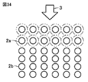
- FIG. 34 shows an example of clogging.
- particles 2a and 2b having the same diameter as the particulate environmental stimulus-responsive polymer material are arranged, and by receiving the air 3 guided from the inlet, it is close to the inlet by the moisture contained in the air 3 It is shown that the side particles 2a swell and become clogged.
- grains 2a the external shape before swelling is shown as a continuous line, and the external shape expanded by swelling is shown with a dashed-two dotted line.
- the particles 2b on the side far from the entrance are not swollen.
- an object of the present invention is to provide a humidity control device that can avoid problems caused by clogging while ensuring sufficient moisture absorption performance.
- a humidity control apparatus includes a first state in which moisture can be absorbed (sorbed), and a first state in which moisture absorbed (sorbed) in the first state is released. 2 when the environmental condition is satisfied, the first state is changed to the second state, and when the environmental condition is not satisfied, the first state is returned.
- the passage housing includes an air inlet that takes in air from the outside, and an air outlet that discharges air that has been taken in from the air inlet and passed through the gaps between the particle groups.
- the particle group includes a first particle group having a first diameter and a second particle group having a second diameter smaller than the first diameter. In the passage housing, the first particle group is disposed closer to the air inlet than the second particle group.
- the present invention since more particles can each absorb moisture, it is possible to provide a humidity control apparatus capable of avoiding problems due to clogging while ensuring sufficient moisture absorption performance.
- Embodiment 1 It is a conceptual diagram of the humidity control apparatus in Embodiment 1 based on this invention. It is a conceptual diagram of the humidity control apparatus in Embodiment 2 based on this invention. It is 1st explanatory drawing of the particle group with which the humidity control apparatus in Embodiment 2 based on this invention is equipped. It is 2nd explanatory drawing of the particle group with which the humidity control apparatus in Embodiment 2 based on this invention is equipped. It is a graph which shows the radius increase rate of the particle group with which the humidity control apparatus in Embodiment 2 based on this invention is equipped. It is explanatory drawing of a mode that air passes through the particle group arrange
- FIG. 25 is a cross-sectional view taken along line XXVI-XXVI in FIG. 24. It is the figure which looked at the dehumidifier in Embodiment 10 based on this invention from the 1st side. It is the figure which looked at the dehumidifier in Embodiment 10 based on this invention from the 2nd side.
- FIG. 28 is a cross-sectional view taken along the line XXIX-XXIX in FIG. It is a front view of the dehumidifier in Embodiment 11 based on this invention. It is a rear view of the dehumidifier in Embodiment 11 based on this invention.
- FIG. 28 is a cross-sectional view taken along the line XXIX-XXIX in FIG. It is a front view of the dehumidifier in Embodiment 11 based on this invention. It is a rear view of the dehumidifier in Embodiment 11 based on this invention.
- FIG. 28 is
- FIG. 31 is a cross-sectional view taken along the line XXXII-XXXII in FIG. 30. It is explanatory drawing of the reproduction
- the polymer gel moisture-absorbing material used in the present invention is a so-called stimulus response type sensitive gel.
- This polymer gel moisture-absorbing material absorbs (sorbs) moisture in the air and discharges water in response to stimulation, thereby condensing water vapor without using supercooling or a large amount of heat. Can be converted to water.
- the volume phase transition that occurs between water and polymer is utilized between water vapor (gas) and water (liquid).
- Embodiment 1 With reference to FIG. 1, the humidity control apparatus in Embodiment 1 based on this invention is demonstrated.
- the humidity control apparatus 101 releases a first state in which moisture can be absorbed (sorbed) and moisture that has been absorbed (sorbed) in the first state.
- a second state that changes from the first state to the second state when the environmental condition is satisfied, and returns to the first state when the environmental condition is not satisfied.
- a particle group 20 mainly composed of a polymer gel moisture-absorbing material having properties, and a passage housing 19 for housing the particle group.
- the passage housing 19 includes an air inlet 17 for taking in air 3 from the outside, an air An air outlet 18 for discharging the air taken in from the inlet 17 and passing through the gap between the particle groups 20, and the particle group 20 includes a first particle group 21 having a first diameter and the first diameter.
- a second particle group 22 having a small second diameter, and a passage housing 1
- the inner, first particles 21 are arranged in the air inlet 17 closer than the second particle group 22.
- FIG. 1 a blower fan for sending air 3 is not shown. Actually, a blower fan is provided at an appropriate position in order to create a flow of air 3 toward the inside of the passage housing 19. In FIG. 1, the size of each particle is exaggerated and enlarged for the convenience of explanation.
- the first state of the particle group 20 is a hydrophilic state, and the second state is a hydrophobic state.
- FIG. 1 a structure for keeping the particle group 20 at a desired position in the passage housing 19 is not shown.
- the particle group 20 is held in a certain section by being sandwiched by mesh members from above and below in the passage housing 19.
- some of the moisture in the air 3 is first absorbed (sorbed) by the first particle group 21 having a large diameter, and then absorbed (sorption) by the second particle group 22 having a small diameter. Therefore, it can avoid that the particle
- Embodiment 2 With reference to FIG. 2, the humidity control apparatus in Embodiment 2 based on this invention is demonstrated.
- the size of the particle diameter is not limited to two stages as described above, and is not less than three stages. May be.
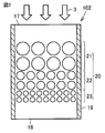
- the humidity control apparatus 102 includes three particle groups as shown in FIG. In the first particle group 21, the second particle group 22, and the third particle group 23, the particle diameters are different from large, medium, and small. Inside the passage housing 19, the first particle group 21, the second particle group 22, and the third particle group 23 are arranged in order from the side close to the air inlet 17. Other basic configurations of the humidity control apparatus may be the same as those described in the first embodiment.
- the particles of the particle group having the smaller diameter rapidly absorb (sorb) excessive moisture. Can be avoided. Therefore, it is possible to provide a humidity control apparatus that can avoid problems due to clogging while ensuring sufficient moisture absorption performance.
- the particle diameter may be four or more. In that case, it arranges in order so that a particle with a large diameter may be located on the side closer to the air inlet 17 and a particle with a smaller diameter on the far side.
- Particles with a smaller radius r have a larger radius increase rate than those with a larger original radius r. This is shown graphically in FIG.
- the three curves shown in FIG. 5 are saturated if the time is sufficiently long, and the possibility of the same radius increase rate cannot be denied. However, for practical use, the operation cycle is repeated after a certain period of time. Is realistic. At least within such a realistic range of time, the magnitude relationship of the radius increase rate that is different from the difference in particle size is maintained even after the lapse of time from the start of moisture absorption.
- FIG. 6 shows a state in which moist air 3 passes when particles having different particle diameters are sequentially arranged in layers.
- the thickness of the arrow indicates the humidity in the air. Each particle absorbs (sorbs) the same amount of moisture. As the air 3 travels, it comes into contact with a larger number of particles, so the humidity decreases.
- FIG. 7 shows a so-called regeneration process, that is, a state in which moisture is taken out by sequentially stimulating moisture particles.
- particles having a large diameter are arranged on the upper side
- particles having a small diameter are arranged on the lower side
- water 5 is taken out from the lower side.
- the thickness of the arrow indicates the amount of moisture that moves.
- the stimulus here is, for example, any one of heat, light, electricity, and pH. By applying this stimulus, it is assumed that the environmental condition for the particle group to change from the first state to the second state is satisfied.
- the stimulus is given in order from the layer arranged on the upper side. By doing so, the state changes from the upper layer to the second state in order.
- the upper layer since the upper layer is already in the second state, even if it touches the water 5 in the liquid state, it cannot be absorbed (sorbed), but the particles in the lower layer are still in the first state. Therefore, the water 5 can be absorbed (sorbed). In this way, water can be sent sequentially to the lower layer. Since almost all the water 5 is collected in the lowermost layer, the water 5 is finally discharged to the outside of the particle group using gravity or centrifugal force.
- FIG. 8 A graph of the particle surface area / volume ratio and the moisture absorption saturation time with respect to the particle radius is shown in FIG.
- the smaller the diameter the larger the ratio of the surface area to the volume of the particle, so the time until the moisture absorption reaches a saturated state is shortened. Therefore, it can be said that the small particles tend to reach saturation in a short time, but as shown in the first and second embodiments, the small particles already remove some moisture by the large particles. Since only the conditioned air arrives, the small particles absorb less moisture and as a result can delay the small particles from reaching saturation.
- Embodiment 3 With reference to FIG. 9, the humidity control apparatus in Embodiment 3 based on this invention is demonstrated.
- the environmental condition in which the polymer gel moisture-absorbing material changes from the first state to the second state is that the temperature is a certain level or higher. Therefore, the stimulus to be given to satisfy the environmental condition is heat.
- the passage housing 19 is provided with a heater 30 for applying heat to the particle group 20.
- Other basic configurations of the humidity control apparatus may be the same as those described in the first or second embodiment.
- Embodiment 4 With reference to FIG. 10, the humidity control apparatus in Embodiment 4 based on this invention is demonstrated.
- the passage housing 19 is divided into a plurality of sections arranged in a direction from the air inlet 17 toward the air outlet 18.
- the particle group 20 is accommodated in the plurality of compartments.
- the heater 30 includes an outer peripheral heater 31 disposed along the outer periphery of the passage housing 19 so as to individually apply heat to each of the plurality of sections.
- a particle group 20 having a different particle diameter is accommodated in each of the plurality of compartments.
- the sections are arranged so that the particle diameters become smaller in order from the air inlet 17 side toward the air outlet 18 side.
- the humidity control apparatus 104 includes a control mechanism 15 that controls the heater 30 so as to sequentially heat the section on the air inlet 17 side to the section on the air outlet 18 side.
- a power supply 10 is connected to operate the control mechanism 15 and the heater 30.
- the particle group 20 is accommodated in a plurality of sections, it is easy to control whether the first state or the second state is set for each section. Therefore, particle groups can be handled efficiently. In addition, since it is divided into a plurality of sections, it is easy to work when exchanging particle groups.
- the humidity control apparatus 105 in the present embodiment is a modification of the humidity control apparatus 104 shown in the fourth embodiment.
- the passage housing is not shown.
- the particle group 20 is arrange
- the cylindrical passage housing in which the particle group 20 is accommodated is slowly rotated around the central axis 14 by a driving unit (not shown).
- the passage housing in which the particle group 20 is accommodated is divided into a ventilation region 11 and a non-venting region 12 in plan view.
- the positional relationship between the vent region 11 and the non-vent region 12 is fixed. Therefore, when the passage housing rotates, the particles in each part pass through the ventilation region 11 and the non-venting region 12 alternately.
- the wind of the air 3 hits the particle group 20 in at least a part of the ventilation region 11.
- region 12 the structure which shields so that the air 3 does not hit directly is provided.
- the particles are heated by a heater (not shown). By the action of the control mechanism 15, heating is performed in order from the top to the bottom.
- the particles in each part alternately pass through the ventilation region 11 and the non-ventilation region 12 due to the rotation of the passage housing. Therefore, by continuing the rotation of the passage housing while operating the heater, Moisture absorption and regeneration can be repeated alternately. Therefore, in this embodiment, it is not necessary to stop the moisture absorption operation for the regeneration process. Therefore, in this Embodiment, the humidity control apparatus which can be continuously operated is realizable.
- the humidity control apparatus in the present embodiment has a first state in which moisture can be absorbed (sorbed) and a second state in which moisture absorbed (sorbed) in the first state is released.
- the polymer gel moisture-absorbing material has a property of changing from the first state to the second state when the environmental condition is satisfied and returning to the first state when the environmental condition is not satisfied.
- the air inlet 17 and the air outlet 18 are covered with a net-like member having a fineness that does not allow the particle group 20 to pass through.
- An outer peripheral heater 31 is provided so as to surround the outer periphery of the passage housing 19.
- the outer peripheral heater 31 is divided into several sections in the vertical direction in FIG. 14, and can be switched ON / OFF separately. Or the structure which can switch ON / OFF separately for each outer periphery heater 31 may be sufficient.
- all the particles are displayed in the same size, but in practice, it is preferable to provide a difference in the particle diameter as described in the above embodiments.
- all particles belonging to the particle group 20 in the passage housing 19 are in the first state, that is, in a state where moisture can be absorbed (sorbed).
- particles in a dry state are displayed as white small circles.
- the humid air 3 is sent into the passage housing 19 from the air inlet 17 by the blower fan 9.
- the air 3 is dehumidified by passing through the gaps between the particle groups 20 and exits from the air outlet 18 as dehumidified air 3e.
- the regeneration step is a step for returning the polymer gel moisture-absorbing material constituting the particle group 20 to a state that can be used again for dehumidification.
- a portion near the upper end of the outer peripheral heater 31 is turned on.
- the particles inside the passage housing 19 are heated, so that the region surrounded by the outer peripheral heater 31 that is ON can be regarded as the heating region 41. Since the particles are not heated below the heating region 41, the non-heating region 42 is formed.
- the heating region 41 the environmental condition is satisfied when the temperature reaches a certain level or more, and as a result, the particles change from the first state to the second state.
- the absorbed (sorbed) moisture is released, but the particles already heated to the second state do not receive moisture.
- the particles in the first state because they have not been heated can receive moisture.
- moisture is sent downward in order.
- Moisture released from a particle may be absorbed (sorbed) by any of the particles present on the lower side, or moved through the gap between the particles without being absorbed (sorbed) by any particle. May be.
- the section where the outer peripheral heater 31 is ON is gradually extended downward, and the heating area 41 is expanded.
- the non-heating area 42 becomes narrower.
- the heating area 41 expands downward, the discharged water 5 is pushed near the lower end of the passage housing 19, and as shown in FIG. 15, the water 5 that has lost its place in the passage housing 19 is It falls from the air outlet 18 in a liquid state.
- the temperature at which the particles change from the first state to the second state is set to a temperature slightly higher than room temperature so that the water exuded from the particles does not evaporate immediately. It is preferable that The temperature sensitive point may be 50 ° C., for example.
- the heater 30 includes an outer peripheral heater 31 provided on the outer periphery and a flat plate heater 32 that separates different sections adjacent in the vertical direction.
- the flat plate heater 32 has a structure through which water and air can pass.
- the flat plate heater 32 may have a net shape.
- the humid air 3 is sent into the passage housing 19 from the air inlet 17 by the blower fan 9.
- the air 3 is dehumidified by passing through the gaps between the particle groups 20 and exits from the air outlet 18 as dehumidified air 3e.
- the heaters on the outer peripheral surface and the upper surface of the section are heated simultaneously in a set for each section partitioned in the passage housing 19, so that the inside of the section is efficiently heated. Will release moisture and the moisture will be expelled to the next lower compartment.
- the heating area 41 expands downward, the discharged water 5 is pushed near the lower end of the passage housing 19, and as shown in FIG. 19, the water 5 that has lost its place in the passage housing 19 is It falls from the air outlet 18 in a liquid state.
- the moisture stored in the particle group 20 can be pushed down efficiently and reliably.
- the said heater is a humidity control apparatus containing the net-like flat plate heater arrange
- casing so that what adjoins among these divisions may be separated.
- the heater is controlled so as to sequentially heat the plurality of sections from the section disposed on the side farther from the outlet from which water should be discharged to the section disposed on the near side. Water extraction method.
- the humidity control apparatus in the present embodiment includes an outer peripheral heater 31 provided on the outer periphery as a heater.
- the passage housing 19 has a cylindrical shape, has a columnar cavity 13 that does not accommodate the particle group 20 along the central axis, and the heater is provided in the particle group 20 from the outer periphery to the inner periphery.
- the outer periphery heater 31 arrange
- the wall material that defines the inner surface of the columnar cavity 13 has a net shape.
- the humid air 3 is sent into the passage housing 19 from the air inlet 17 by the blower fan 9.
- the air 3 is dehumidified by passing through the gaps between the particle groups 20 disposed inside the passage housing 19 and outside the columnar cavity 13, and exits from the air outlet 18 as dehumidified air 3 e.
- the outer peripheral heaters 31 are simultaneously turned on over the entire section from the upper end to the lower end. By carrying out like this, it heats up sequentially from the particle
- the columnar cavity 13 is provided in the passage housing 19, a mechanism for controlling the heaters to be turned on in order for each part is unnecessary.
- an appropriate material having a higher thermal conductivity than that of the polymer gel moisture-absorbing material for example, a member made of metal, resin, or the like is directed from the outer periphery of the housing to the center side You may arrange
- the material used here is a metal
- examples of the metal include aluminum and stainless steel.
- Aluminum is particularly preferable because of its high thermal conductivity.
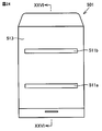
- FIG. 24 shows a view of the dehumidifier 501 in the present embodiment from the front
- FIG. 25 shows a view from the back.
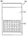
- On the front surface 513 of the dehumidifier 501 an air outlet 511 a is provided at the lower part, and an air outlet 511 b is provided at the upper part.
- the back surface 514 is provided with an intake port, and a filter 512 covers the intake port.
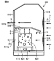
- FIG. 26 is a cross-sectional view taken along the line XXVI-XXVI in FIG.
- a first intake fan 516 arranged at the lower part and a second intake fan 517 arranged at the upper part are arranged inside the back surface 514.
- the internal space of the housing is separated vertically by a condensation plate 518.
- the end of the condensation plate 518 on the back surface 514 side is bent downward.
- a polymer hygroscopic material 520 is disposed below the dew condensation plate 518.
- the polymer hygroscopic material 520 holds the particle group 20 by applying the concept described in the first to eighth embodiments.
- the polymer hygroscopic material 520 is displayed as a porous block, but this is merely an example and is not necessarily a block.
- air does not pass from top to bottom as described in Embodiments 1 to 8, but air passes in the lateral direction. Therefore, the direction of the arrangement of the particle group 20 is 90 ° different from that described in the first to eighth embodiments.
- the polymer hygroscopic material 520 is placed on a table 525.
- a heat source 521 is disposed below the table 525.
- the heat source 521 is disposed so that the polymer moisture absorbent 520 can be heated from below via the table 525.
- a tank 515 for receiving and storing water is disposed at the lowermost part of the dehumidifier 501.
- the first intake fan 516 is turned on while the heat source 521 and the second intake fan 517 are turned off.
- the external air 3 is guided to the lower space inside the housing by the first intake fan 516.
- the air 3 is dehumidified by passing through the polymer hygroscopic material 520, becomes air 3 e, and is discharged from the outlet 511 a below the front surface 511.
- the first intake fan 516 is turned off, and the heat source 521 and the second intake fan 517 are turned on.
- the polymer moisture absorbent 520 is heated by the heat source 521, and moisture is released from the polymer moisture absorbent 520.
- the water that has oozed out in the liquid state is guided to the tank 515 by gravity.
- Moisture, that is, water vapor 6 released in a gaseous state touches the lower surface of the dew condensation plate 518.
- the air 3 guided from the outside by the second intake fan 517 passes while cooling the upper surface of the dew condensation plate 518 and exits from the air outlet 511 b on the upper side of the front surface 513.
- the water vapor 6 that has touched the lower surface of the dew condensation plate 518 is cooled by the dew condensation plate 518 and is condensed to form water 5 in a liquid state. Since one end of the dew condensation plate 518 is inclined, the water 5 adhering to this portion is guided to the lower end of the dew condensation plate 518 by the inclination and falls and is received by the tank 515.
- the portion near the front surface 513 of the dew condensation plate 518 is displayed as extending horizontally, but actually this portion may also be inclined so as to decrease as it approaches the back surface 514 side. preferable.
- moisture released as water vapor from the polymer moisture absorbent 520 can also be condensed by the action of the condensation plate 518 and recovered as liquid water.
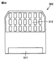
- FIG. 27 shows a view of the dehumidifier 502 in the present embodiment from one side
- FIG. 28 shows a view from the other side.
- the blower outlet 511 is provided in the lower part.
- An intake port is provided in the upper part on the same side as the air outlet 511, and the filter 512 covers the intake port.
- FIG. 29 is a cross-sectional view taken along the line XXIX-XXIX in FIG.
- a common intake fan 519 is provided at one location.
- a dew condensation plate 518i is provided so as to vertically separate the internal space of the housing.
- a polymer hygroscopic material 520 is disposed below the dew condensation plate 518i.
- a tank 515 for receiving and storing water is disposed at the lowermost part of the dehumidifier 502.
- a heat source 522 is disposed in a passage connecting the upper space and the lower space of the dew condensation plate 518i.
- the common intake fan 519 is turned on while the heat source 522 is turned off.
- the common intake fan 519 guides air 3 from the outside into the housing.
- the air 3 passes through the upper space of the dew condensation plate 518i, wraps around the lower space, and passes through the polymer hygroscopic material 520.
- the air 3 is dehumidified by passing through the polymer hygroscopic material 520, and becomes air 3 e and is discharged from the outlet 511 to the outside.
- the common intake fan 519 is turned on while the heat source 522 is turned on.
- the common intake fan 519 guides air 3 from the outside into the housing. Since the air 3 is warmed by the heat source 522 and passes through the polymer hygroscopic material 520, the temperature of the particles contained in the polymer hygroscopic material 520 rises to a second state, that is, a hydrophobic state.
- the water 5 released from the polymer hygroscopic material 520 in a liquid state falls by gravity and is received by the tank 515.
- the water, that is, the water vapor 6 released from the polymer hygroscopic material 520 in a gaseous state touches the lower surface of the inclined portion of the dew condensation plate 518i.
- the inclined portion of the dew condensation plate 518i is cooled.
- the water vapor 6 is cooled by the dew condensation plate 518i, and is condensed to form water 5 in a liquid state.
- the water 5 adhering to the lower surface of the inclined portion of the dew condensation plate 518i is guided downward by gravity and received by the tank 515.
- moisture released as water vapor from the polymer hygroscopic material 520 can also be condensed by the action of the condensation plate 518i and recovered as liquid water.
- the same common intake fan 519 is used for both dehumidification and regeneration, the number of fans installed can be reduced.
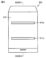
- FIG. 30 shows a view of the dehumidifier 503 in the present embodiment from the front
- FIG. 31 shows a view from the back.
- On the front surface 513 of the dehumidifier 501 an air outlet 511 a is provided at the lower part, and an air outlet 511 b is provided at the upper part.
- the back surface 514 is provided with an intake port, and a filter 512 covers the intake port.
- FIG. 32 shows a cross-sectional view taken along the line XXXII-XXXII in FIG.
- a common intake fan 519 is provided at one lower position inside the back surface 514.
- the internal space of the housing is vertically separated by a condensation plate 518j.
- the dew condensation plate 518j is curved so as to fall as it approaches the back surface 514 side.
- the dew condensation plate 518j can move up and down in the casing.
- a polymer hygroscopic material 520 is disposed below the dew condensation plate 518j in the same manner as described in the ninth embodiment. The point that the polymer hygroscopic material 520 is placed on the stand 525, the point that the heat source 521 and the tank 515 are arranged are the same as those described in the ninth embodiment.
- the dew condensation plate 518j is disposed at a high position as shown in FIG. 32, and the common intake fan 519 is turned on while the heat source 521 is turned off.
- the external air 3 is guided to the lower space inside the housing by the common intake fan 519.
- the air 3 is dehumidified by passing through the polymer hygroscopic material 520, becomes air 3 e, and is discharged from the outlet 511 a below the front surface 511.
- the dew condensation plate 518j moves downward as shown by an arrow 91 in FIG. 32, and becomes as shown in FIG. That is, the dew condensation plate 518j is disposed at a low position.
- the heat source 521 and the common intake fan 519 are turned on.
- the polymer moisture absorbent 520 is heated by the heat source 521, and moisture is released from the polymer moisture absorbent 520.
- the water that has oozed out in the liquid state is guided to the tank 515 by gravity.
- Moisture that is, water vapor 6 released in the gaseous state touches the lower surface of the dew condensation plate 518j.
- the air 3 guided from the outside by the common intake fan 519 passes through the upper surface of the dew condensation plate 518j while cooling and exits from the air outlet 511b on the upper side of the front surface 513.
- the water vapor 6 that has touched the lower surface of the dew condensation plate 518j is cooled by the dew condensation plate 518j, and is condensed to form water 5 in a liquid state. Since the dew condensation plate 518j is curved, the water 5 adhering to the dew condensation plate 518j is guided to the lower end of the dew condensation plate 518j by the inclination, falls, and is received by the tank 515.
- the same effect as in the tenth embodiment can be obtained.
- the passage of air can be clearly switched by the movement of the dew condensation plate 518j, it can operate efficiently.
- a hygroscopic material whose main material is a polymer gel hygroscopic material that has the property of changing from the state to the second state and returning to the first state when the temperature is not higher than the predetermined temperature;
- a first blower fan that induces and applies outside air to the hygroscopic material in the first state;
- a dew plate disposed at a position to receive water vapor released from the moisture absorbent material in the second state;
- a dehumidifying device comprising: a second blower fan that can apply wind to a surface of the dew condensation plate opposite to the surface that receives the water vapor.
- the present invention can be used for a humidity control apparatus.
Landscapes
- Engineering & Computer Science (AREA)
- Chemical & Material Sciences (AREA)
- Combustion & Propulsion (AREA)
- Mechanical Engineering (AREA)
- General Engineering & Computer Science (AREA)
- Analytical Chemistry (AREA)
- General Chemical & Material Sciences (AREA)
- Oil, Petroleum & Natural Gas (AREA)
- Chemical Kinetics & Catalysis (AREA)
- Drying Of Gases (AREA)
- Central Air Conditioning (AREA)
Abstract
調湿装置(101)は、水分を吸収(収着)しうる第1の状態と、水分を放出する第2の状態とを有し、環境条件が満たされると前記第1の状態から前記第2の状態へと変化し、かつ、前記環境条件が満たされなくなったときには前記第1の状態に戻る性質を有する高分子ゲル吸湿材料を主材料とする粒子群(20)と、粒子群(20)を収容する通路筐体(19)とを備える。通路筐体(19)は、外部から空気を取り込む空気入口(17)と、粒子群(20)の隙間を通過した空気を排出する空気出口(18)とを有する。粒子群(20)は、第1の径を有する第1粒子群(21)と、前記第1の径より小さな第2の径を有する第2粒子群(22)とを含む。通路筐体(19)内において、第1粒子群(21)は第2粒子群(22)よりも空気入口(17)寄りに配置されている。
Description
本発明は、調湿装置に関するものである。
除湿および調湿を行なうための装置としては、冷凍サイクル式とゼオライト式とがある。「冷凍サイクル式」は、主にコンプレッサすなわち圧縮機を内蔵し、エバポレータすなわち蒸発器で室内空気を冷却することにより空気内の湿度を結露させ、除湿するものである。「ゼオライト式」は、室内の空気中の水分をロータに吸湿させ、吸湿したロータに電気ヒータで作った高温の風を当て、ロータ内の水分を高温・高湿の空気として取り出し、その空気を室内空気で冷却することにより、高温・高湿の空気に含まれる水分を結露させて取り出すものである。
冷凍サイクル式の例が記載された文献としては、特開2003-144833号公報(特許文献1)を挙げることができる。ゼオライト式の例が記載された文献としては、特開2001-259349号公報(特許文献2)を挙げることができる。両者の特徴を合わせた構成は、特開2005-34838号公報(特許文献3)に記載されている。
大規模空調システムとして、吸湿性を有する素子、すなわち、たとえばゼオライトなどを用いて、この素子による水分の吸着および離脱の現象を利用して冷房などの空調を行なう、いわゆるデシカント空調システムも普及している。地球環境保護の要請から現在も盛んに高効率な調湿システムが開発されている。その一例は、特開平5-301014号公報(特許文献4)に記載されている。
吸水剤に関しては、特開2012-161789号公報(特許文献5)に記載されている。
ゲル状の高分子が溶媒中におかれた場合の挙動の特徴のひとつとして、溶媒が水である場合にはその吸収速度および放出速度は高分子の大きさの2乗に比例することが知られている。このことに関する文献としては、T. Tanakaらによる"Critical Kinetics of Volume Phase Transition of Gels", Physical Review Letters, Vol.55, No.22, pp.2455-2458, The American Physical Society, (1985)(非特許文献1)を挙げることができる。
T. Tanakaらによる"Critical Kinetics of Volume Phase Transition of Gels", Physical Review Letters, Vol.55, No.22, pp.2455-2458, The American Physical Society, (1985)
粒子状の環境刺激応答性高分子材料は粒径が小さいほど吸湿速度が速く、高分子材料の体積に比べて吸湿率が高くなる傾向があった。そのため粒径の小さな粒子ほど、吸湿前に比べて飽和吸湿後の粒子半径の増加率及び体積増加率が大きくなる。このように粒子半径が急激に増加することに起因して、吸湿後または吸湿過程において粒子同士が互いに固着して目詰まりする場合があった。図34に目詰まりの例を示す。ここでは、粒子状の環境刺激応答性高分子材料として同じ径の粒子2a,2bが配列されており、入口から導かれる空気3を受けることによって、空気3に含まれていた水分によって入口に近い側の粒子2aが膨潤し、目詰まりすることが示されている。粒子2aについては、膨潤前の外形を実線で示し、膨潤により拡大した外形を2点鎖線で示す。入口から遠い側の粒子2bは膨潤していない。
このように目詰まりが生じると、空気の流れが阻害され、圧力損失をもたらす。粒子状の環境刺激応答性高分子材料が充填されて上流から下流へと並ぶ各部位をそれぞれ「層」として把握できるものと仮定すると、ある層で高分子材料の粒子が目詰まりして固着してしまうと、その部位より下流側にある粒子の層への空気の流れは阻害され、全体としての吸湿率は低下する。
このような除湿効率の低下をもたらす粒子同士の固着を防ぐためには、高分子材料の粒径分布を一定ではなくランダムにすることが考えられる。たとえば、径が大きな粒子(以下「大粒子」という。)と径が小さな粒子(以下「小粒子」という。)とを混在させて配置する。しかし、そのようにしても図35に示すように、大粒子2c同士の間に小粒子2dが入ることで、粒子同士の固着が生じてしまう。
また、吸湿による固着を防ぐために比較的大きな粒径、たとえば数mm程度の粒子に揃えるということも考えられる。この場合、体積当たりの表面積が小さくなるため、吸湿速度が低下してしまうという問題がある。
一方、小さな粒径の粒子のみに揃えて粒子同士が固着してしまう前に吸湿工程を終えることができるようなシステムも考えられるが、このようなシステムでは吸湿性能を発揮できる時間が短すぎて、求められる除湿作業に見合うほどの十分な吸湿性能が得られないことが危惧される。
そこで、本発明は、十分な吸湿性能を確保しつつ、目詰まりによる問題を回避できるような調湿装置を提供することを目的とする。
上記目的を達成するため、本発明に基づく調湿装置は、水分を吸収(収着)しうる第1の状態と、上記第1の状態のときに吸収(収着)した水分を放出する第2の状態とを有し、環境条件が満たされると上記第1の状態から上記第2の状態へと変化し、かつ、上記環境条件が満たされなくなったときには上記第1の状態に戻る性質を有する高分子ゲル吸湿材料を主材料とする粒子群と、上記粒子群を収容する通路筐体とを備える。上記通路筐体は、外部から空気を取り込む空気入口と、上記空気入口から取り込まれて上記粒子群の隙間を通過した空気を排出する空気出口とを有する。上記粒子群は、第1の径を有する第1粒子群と、上記第1の径より小さな第2の径を有する第2粒子群とを含む。上記通路筐体内において、上記第1粒子群は上記第2粒子群よりも上記空気入口寄りに配置されている。
本発明によれば、より多くの粒子がそれぞれ吸湿することができるので、十分な吸湿性能を確保しつつ、目詰まりによる問題を回避できるような調湿装置を提供することができる。
本発明で用いられる高分子ゲル吸湿材料は、いわゆる刺激応答型の感応ゲルである。この高分子ゲル吸湿材料が空気中の水分を吸収(収着)する現象と、刺激に応答して水を吐き出す現象とを利用することで、過冷却や大きな熱量を用いることなく、水蒸気を凝縮水に変換することができる。ここでは、水と高分子との間で起こる体積相転移を水蒸気(気体)と水(液体)との間で利用している。刺激により、高分子ゲル吸湿材料を親水化させたり疎水化させたりすることによって、クラスター状の水分子を高分子ネットワーク内に結合して固定化したり、高分子ネットワークから結合を外して水分子を流動化させたりすることができる。
(実施の形態1)
図1を参照して、本発明に基づく実施の形態1における調湿装置について説明する。
図1を参照して、本発明に基づく実施の形態1における調湿装置について説明する。
図1に示すように、本実施の形態における調湿装置101は、水分を吸収(収着)しうる第1の状態と、前記第1の状態のときに吸収(収着)した水分を放出する第2の状態とを有し、環境条件が満たされると前記第1の状態から前記第2の状態へと変化し、かつ、前記環境条件が満たされなくなったときには前記第1の状態に戻る性質を有する高分子ゲル吸湿材料を主材料とする粒子群20と、前記粒子群を収容する通路筐体19とを備え、通路筐体19は、外部から空気3を取り込む空気入口17と、空気入口17から取り込まれて粒子群20の隙間を通過した空気を排出する空気出口18とを有し、粒子群20は、第1の径を有する第1粒子群21と、前記第1の径より小さな第2の径を有する第2粒子群22とを含み、通路筐体19内において、第1粒子群21は第2粒子群22よりも空気入口17寄りに配置されている。
図1では、空気3を送り込むための送風ファンは図示省略している。実際には、通路筐体19内に向かう空気3の流れを作り出すために適当な位置に送風ファンが設けられる。図1では、各粒子のサイズは説明の便宜のために誇張して大きく表示している。
粒子群20の第1の状態とは親水性の状態であり、第2の状態とは疎水性の状態である。
図1では、粒子群20を通路筐体19内の所望の位置にとどめておくための構造は図示省略している。たとえば通路筐体19内で上下から網状の部材で挟み込んで粒子群20を一定の区間内に保持することが考えられる。
本実施の形態では、径が大きな第1粒子群21によってまず空気3中の水分のいくらかが吸収(収着)され、その後で径が小さな第2粒子群22による吸収(収着)が行なわれるので、第2粒子群22の粒子が過度に膨潤することを避けることができ、より多くの粒子がそれぞれ吸湿することができる。したがって、十分な吸湿性能を確保しつつ、目詰まりによる問題を回避できるような調湿装置を提供することができる。
(実施の形態2)
図2を参照して、本発明に基づく実施の形態2における調湿装置について説明する。
図2を参照して、本発明に基づく実施の形態2における調湿装置について説明する。
実施の形態1では、粒子群20の中に径が異なる2通りの粒子群のみを備える例を示したが、粒子の径の大きさはこのように2段階のみならず3段階以上となっていてもよい。
本実施の形態における調湿装置102では、図2に示すように、3つの粒子群を備えている。第1粒子群21、第2粒子群22、第3粒子群23で、粒子の径は大、中、小と異なっている。通路筐体19の内部においては、空気入口17に近い側から順に、第1粒子群21、第2粒子群22、第3粒子群23と並ぶように配置されている。この調湿装置におけるその他の基本的な構成は、実施の形態1で説明したものと同様であってよい。
本実施の形態では、外部から取り込まれた空気に対しては、径が大きな粒子群から順に接することとなるので、径が小さな粒子群の粒子が急速に過度な水分を吸収(収着)してしまうことを避けることができる。したがって、十分な吸湿性能を確保しつつ、目詰まりによる問題を回避できるような調湿装置を提供することができる。
ここでは、粒子径が3通りの例を示したが、粒子径は4通り以上であってもよい。その場合、空気入口17から近い側に径が大きい粒子、遠い側に径が小さい粒子が位置するように順に並べて配置される。
(原理の説明)
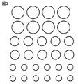
粒径を制御して各粒径ごとに層状に配置した場合の吸湿前後の変化について、図3および図4を参照して説明する。図3に例示するように、幾通りかの異なる径の粒子が層状に配置されているものとする。これらの粒子が全て同様に十分に吸湿した場合、図4に示すように各粒子は膨潤して拡大する。図4では各粒子の膨潤前のサイズを2点鎖線で表示し、膨潤後のサイズを実線で表示している。粒子の半径に注目し、膨潤前の半径をr、膨潤後の半径をr′とすると、半径増加率は(r′-r)/rで定義することができる。元の半径rが大きいものに比べて半径rが小さい粒子の方が半径増加率が大きい。このことは図5にグラフで示される。図5に示した3本の曲線は、十分に時間を長くかければそれぞれ飽和し、同じ半径増加率となる可能性も否定できないが、実用のためには、一定時間で打ち切って動作サイクルを繰り返させることが現実的である。少なくともそのような現実的な時間の長さの範囲内に限って見れば、粒径の違いに相違する半径増加率の大小関係は、吸湿開始から時間が経過しても維持される。
粒径を制御して各粒径ごとに層状に配置した場合の吸湿前後の変化について、図3および図4を参照して説明する。図3に例示するように、幾通りかの異なる径の粒子が層状に配置されているものとする。これらの粒子が全て同様に十分に吸湿した場合、図4に示すように各粒子は膨潤して拡大する。図4では各粒子の膨潤前のサイズを2点鎖線で表示し、膨潤後のサイズを実線で表示している。粒子の半径に注目し、膨潤前の半径をr、膨潤後の半径をr′とすると、半径増加率は(r′-r)/rで定義することができる。元の半径rが大きいものに比べて半径rが小さい粒子の方が半径増加率が大きい。このことは図5にグラフで示される。図5に示した3本の曲線は、十分に時間を長くかければそれぞれ飽和し、同じ半径増加率となる可能性も否定できないが、実用のためには、一定時間で打ち切って動作サイクルを繰り返させることが現実的である。少なくともそのような現実的な時間の長さの範囲内に限って見れば、粒径の違いに相違する半径増加率の大小関係は、吸湿開始から時間が経過しても維持される。
図4に示したように、空気入口付近では粒子の元の半径rが大きく半径増加率が小さいので、吸湿した後でも粒子の大きさはあまり変わらない。したがって、目詰まりを起こしにくい。空気出口付近の小粒子は半径増加率が大きいが、これらの小粒子が目詰まりを起こす前に吸湿工程を終えればよい。その場合でも、空気の流れが小粒子の層に達する前により上流側に位置する大粒子によって十分に吸湿が行なわれるので、全体としては十分な吸湿性能が発揮される。
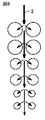
異なる粒径の粒子が順に層状に配置されている場合に、湿った空気3が通っていく様子を図6に示す。図6においては矢印の太さは空気中の湿度を示す。各粒子は、それぞれ同じ量の水分を吸収(収着)する。空気3は、進行するにつれてより多くの個数の粒子と触れ合うので、湿度が低下していく。
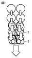
いわゆる再生工程、すなわち、吸湿した粒子群に対して、逐次、刺激を与えて水分を取り出す際の様子を図7に示す。この図では、上側に径が大きい粒子が配置され、下側に径が小さい粒子が配置され、下側から水5を取り出す例を示している。図7においては矢印の太さは移動する水分の量を示す。ここでいう刺激とは、たとえば熱、光、電気、pHのうちのいずれかである。この刺激が与えられることによって、粒子群が第1の状態から第2の状態へと変化するための環境条件が満たされるものとする。図7に示した例では、上側に配置された層から順に刺激を与えている。こうすることによって、上側にある層から順に第2の状態へと変化する。上側の層から下側の層へと順に刺激を与えていく途中のある時点を想定して説明する。刺激を与えられたことによって第2の状態に変化した層は、それまで吸収(収着)していた水分を液体状態の水5として放出する。この時点では、すぐ下側の層の粒子はまだ第1の状態であるのでこの水5を吸収(収着)することができる。このようにして上側の層から下側に隣接する層へと水5を引き渡すことができる。さらに下側の層の粒子にも順次刺激を与えていくと、下側の層においても第1の状態から第2の状態へと変化し、水を保持していることができなくなるので、水は放出される。この時点では上側の層は既に第2の状態であるので、たとえ液体状態の水5に触れてもこれを吸収(収着)することができないが、さらに下側の層の粒子はまだ第1の状態であるので水5を吸収(収着)することができる。このようにして、水を順に下側の層へと送っていくことができる。最下層においては、ほぼ全ての水5が集められるので、重力や遠心力などを利用して、最終的に水5は粒子群の外側に放出される。
粒子半径に対する粒子表面積/体積比および吸湿飽和時間のグラフを図8に示す。図8に示されるように、径が小さな粒子ほど粒子の体積に対する表面積の割合が大きくなるので、吸湿が飽和状態に達するまでの時間が短くなる。したがって、小粒子は短い時間のうちに飽和に達してしまう傾向があるといえるが、本実施の形態1,2で示したように、小粒子のところには、大粒子によって既にある程度水分を除去された空気が到達するのみであるので、小粒子が吸湿する水分は少なく、その結果、小粒子が飽和に達するのを遅らせることができる。
(実施の形態3)
図9を参照して、本発明に基づく実施の形態3における調湿装置について説明する。
図9を参照して、本発明に基づく実施の形態3における調湿装置について説明する。
本実施の形態では、高分子ゲル吸湿材料が第1の状態から第2の状態へと変化する環境条件は一定以上の温度であることである。したがって、環境条件を満たすために与えるべき刺激は熱である。図9に示すように、本実施の形態における調湿装置103では、通路筐体19には、粒子群20に熱を加えるためのヒータ30が設けられている。この調湿装置におけるその他の基本的な構成は、実施の形態1または2で説明したものと同様であってよい。
本実施の形態では、通路筐体19に設けられたヒータ30によって粒子群20に熱を与えることができるので、粒子群20による吸湿工程を終え、粒子群20の再生工程を行なう場合には、ヒータ30を作動させることによって容易に行なうことができる。
(実施の形態4)
図10を参照して、本発明に基づく実施の形態4における調湿装置について説明する。
図10を参照して、本発明に基づく実施の形態4における調湿装置について説明する。
本実施の形態における調湿装置104では、図10に示すように、通路筐体19は、空気入口17から空気出口18に向かう方向に並ぶ複数の区画に分かれている。粒子群20は前記複数の区画に分けて収容されている。ヒータ30は、前記複数の区画の各々に個別に熱を加えるように通路筐体19の外周に沿って配置された外周ヒータ31を含む。
さらに好ましいことに、本実施の形態では、前記複数の区画の各々には、異なる粒子径の粒子群20が収容されている。図10の右側に引き出して拡大して示すように、各区画は、空気入口17側から空気出口18側に向かって粒子径が順に小さくなるように配列されている。調湿装置104は、空気入口17側の区画から空気出口18側の区画へと順に加熱していくようにヒータ30を制御する制御機構15を備える。制御機構15およびヒータ30を動作させるために、電源10が接続されている。
本実施の形態では、粒子群20が複数の区画に分けて収容されているので、区画ごとに第1の状態とするか第2の状態とするかを制御しやすい。したがって、粒子群を効率良く扱うことができる。また、複数の区画に分かれていることから、粒子群を交換する際にも作業がしやすい。
(実施の形態5)
図11を参照して、本発明に基づく実施の形態5における調湿装置について説明する。本実施の形態における調湿装置105は、実施の形態4で示した調湿装置104の変形例である。図11に示した調湿装置105では、通路筐体は図示省略されている。調湿装置105では、円筒形の多層構造として、粒子群20が配置されている。調湿装置105では、粒子群20が収まった円筒形状の通路筐体は、図示しない駆動手段によって中心軸14の周りにゆっくりと回転駆動される。粒子群20が収まった通路筐体は、平面的に見て、通気領域11と非通気領域12とに分けられている。通路筐体の回転にかかわらず、通気領域11と非通気領域12との位置関係は固定されている。したがって、通路筐体が回転することによって、各部位の粒子は、通気領域11と非通気領域12とを交互に通過することとなる。空気3の風は通気領域11の少なくとも一部において粒子群20に当たる。非通気領域12においては、空気3が直接当たらないように遮蔽する構造が設けられている。非通気領域12においては、粒子は図示しないヒータによって加熱される。制御機構15の働きにより、上から下へ順に加熱される。
図11を参照して、本発明に基づく実施の形態5における調湿装置について説明する。本実施の形態における調湿装置105は、実施の形態4で示した調湿装置104の変形例である。図11に示した調湿装置105では、通路筐体は図示省略されている。調湿装置105では、円筒形の多層構造として、粒子群20が配置されている。調湿装置105では、粒子群20が収まった円筒形状の通路筐体は、図示しない駆動手段によって中心軸14の周りにゆっくりと回転駆動される。粒子群20が収まった通路筐体は、平面的に見て、通気領域11と非通気領域12とに分けられている。通路筐体の回転にかかわらず、通気領域11と非通気領域12との位置関係は固定されている。したがって、通路筐体が回転することによって、各部位の粒子は、通気領域11と非通気領域12とを交互に通過することとなる。空気3の風は通気領域11の少なくとも一部において粒子群20に当たる。非通気領域12においては、空気3が直接当たらないように遮蔽する構造が設けられている。非通気領域12においては、粒子は図示しないヒータによって加熱される。制御機構15の働きにより、上から下へ順に加熱される。
本実施の形態では、各部位の粒子は通路筐体の回転によって通気領域11と非通気領域12とを交互に通過するので、ヒータを作動させたままで通路筐体の回転を続けることで、各部位に対する吸湿と再生とを交互に繰り返すことができる。したがって、本実施の形態では、再生工程のために吸湿作業を停止する必要がない。よって、本実施の形態では、連続運転が可能な調湿装置を実現することができる。
(実施の形態6)
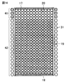
図12~図15を参照して、本発明に基づく実施の形態6における調湿装置について説明する。本実施の形態における調湿装置は、水分を吸収(収着)しうる第1の状態と、前記第1の状態のときに吸収(収着)した水分を放出する第2の状態とを有し、環境条件が満たされると前記第1の状態から前記第2の状態へと変化し、かつ、前記環境条件が満たされなくなったときには前記第1の状態に戻る性質を有する高分子ゲル吸湿材料を主材料とする粒子群20と、前記粒子群を収容する通路筐体19とを備え、通路筐体19は、外部から空気3を取り込む空気入口17と、空気入口17から取り込まれて粒子群20の隙間を通過した空気を排出する空気出口18とを有する。空気入口17および空気出口18においては、粒子群20を通過させない程度の目の細かさの網状の部材によって蓋がされている。通路筐体19の外周を取り囲むように外周ヒータ31が設けられている。外周ヒータ31は、図14における上下方向にいくつかの区間に分かれており、それぞれ別個にON/OFFを切り替えることができる。あるいは、外周ヒータ31は1本ずつ別々にON/OFFを切り替えることができる構成であってもよい。
図12~図15を参照して、本発明に基づく実施の形態6における調湿装置について説明する。本実施の形態における調湿装置は、水分を吸収(収着)しうる第1の状態と、前記第1の状態のときに吸収(収着)した水分を放出する第2の状態とを有し、環境条件が満たされると前記第1の状態から前記第2の状態へと変化し、かつ、前記環境条件が満たされなくなったときには前記第1の状態に戻る性質を有する高分子ゲル吸湿材料を主材料とする粒子群20と、前記粒子群を収容する通路筐体19とを備え、通路筐体19は、外部から空気3を取り込む空気入口17と、空気入口17から取り込まれて粒子群20の隙間を通過した空気を排出する空気出口18とを有する。空気入口17および空気出口18においては、粒子群20を通過させない程度の目の細かさの網状の部材によって蓋がされている。通路筐体19の外周を取り囲むように外周ヒータ31が設けられている。外周ヒータ31は、図14における上下方向にいくつかの区間に分かれており、それぞれ別個にON/OFFを切り替えることができる。あるいは、外周ヒータ31は1本ずつ別々にON/OFFを切り替えることができる構成であってもよい。
図12では、全ての粒子を同じサイズで表示しているが、実際には、これまでの実施の形態で説明してきたように、粒子径に差を設けていることが好ましい。図12では、通路筐体19内の粒子群20に属する全ての粒子が第1の状態、すなわち、水分を吸収(収着)しうる状態である。図面では、説明の便宜のため、乾燥状態にある粒子を白い小円で表示するものとする。
除湿の工程においては、図12に示すように、送風ファン9によって空気入口17から湿った空気3が通路筐体19の内部に送り込まれる。空気3は、粒子群20の隙間を通過することによって除湿され、除湿済の空気3eとして空気出口18から出ていく。
このように空気3の除湿を続けた結果、ほぼ全ての粒子がある程度の水分を吸収(収着)した状態になる。その状態を図13に示す。図13に示した状態であってもは、必ずしも各粒子が飽和状態であるとは限らないい。図面では、説明の便宜のため、ある程度以上の水分を蓄えた状態にある粒子をドットハッチング付きの小円で表示するものとする。
次に、再生の工程について説明する。再生の工程とは、粒子群20となっている高分子ゲル吸湿材料を再び除湿に使用可能な状態に戻すための工程である。図14に示すように、外周ヒータ31の上端近傍の一部がONとなる。この部分では通路筐体19の内部の粒子が加熱されるので、ONとなっている外周ヒータ31に囲まれた領域を加熱領域41とみなすことができる。加熱領域41よりも下側では粒子に対する加熱は行なわれていないので、非加熱領域42となっている。加熱領域41では、温度が一定以上に達することによって環境条件が満たされ、その結果、粒子が第1の状態から第2の状態へと変化する。第2状態では、吸収(収着)していた水分を放出するということになるが、既に加熱されて第2の状態になっている粒子は水分を受け取らない。一方、まだ加熱されていないことによって第1の状態である粒子は水分を受け取ることができる。その結果、水分は下方へ順に送られることとなる。ある粒子から放出された水分は下側に存在するいずれかの粒子によって吸収(収着)されてもよいし、いずれの粒子にも吸収(収着)されずに粒子同士の隙間を流れて移動してもよい。
図15に示すように、外周ヒータ31がONとなっている区間は徐々に下方に向かって延長していき、加熱領域41は拡大していく。加熱領域41が拡大するのと引き換えに非加熱領域42は狭くなっていく。加熱領域41の下方への拡大に伴い、放出された水5は通路筐体19の下端近傍に押しやられ、図15に示されるように、通路筐体19内での行き場を失った水5は液体状態で空気出口18から落下する。
本実施の形態では、上から下へと徐々に加熱領域41を拡大することによって、粒子群20に蓄えられていた水分を効率良く下へと押しやることができる。
なお、粒子が第1の状態から第2の状態へと変化する温度、すなわち、いわゆる感温点は、粒子からにじみ出た水がすぐには蒸発しないように、常温よりやや高い程度の温度に設定されていることが好ましい。感温点はたとえば50℃であってもよい。
(実施の形態7)
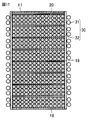
図16~図19を参照して、本発明に基づく実施の形態7における調湿装置について説明する。本実施の形態における調湿装置では、ヒータ30は、外周に設けられた外周ヒータ31と、上下方向に隣接する異なる区画同士を隔てる平板ヒータ32とを含む。平板ヒータ32は水や空気が通過できるような構造となっている。たとえば平板ヒータ32は網状となっていてもよい。
図16~図19を参照して、本発明に基づく実施の形態7における調湿装置について説明する。本実施の形態における調湿装置では、ヒータ30は、外周に設けられた外周ヒータ31と、上下方向に隣接する異なる区画同士を隔てる平板ヒータ32とを含む。平板ヒータ32は水や空気が通過できるような構造となっている。たとえば平板ヒータ32は網状となっていてもよい。
除湿の工程においては、図16に示すように、送風ファン9によって空気入口17から湿った空気3が通路筐体19の内部に送り込まれる。空気3は、粒子群20の隙間を通過することによって除湿され、除湿済の空気3eとして空気出口18から出ていく。
このように空気3の除湿を続けた結果、ほぼ全ての粒子がある程度以上の水分を吸収(収着)した状態になる。その状態を図17に示す。図17に示した状態であっても、必ずしも各粒子が飽和状態であるとは限らない。
次に、再生の工程について説明する。図18に示すように、まず最初に、外周ヒータ31の上端近傍の一部と、粒子群20の最上面に位置する平板ヒータ32とがONとなる。このように上から1つ目の区画が外周面と上面とから加熱され、この区画の内部にある粒子群が加熱により環境条件が満たされ、その結果、第1の状態から第2の状態へと変化する。図18では、一番上の1つの区画だけが加熱領域41となっており、他の区画は非加熱領域42となっている。このとき、加熱領域41においては水分が液体状態の水として放出され、この水は1つ下隣りの区画に移動する。このように、通路筐体19内で区切られた各区画に対して、当該区画の外周面および上面のヒータがセットで同時に加熱を行なうことにより、当該区画内は効率良く加熱されるので、粒子は水分を放出して水分は下隣りの区画へと追いやられることとなる。加熱領域41の下方への拡大に伴い、放出された水5は通路筐体19の下端近傍に押しやられ、図19に示されるように、通路筐体19内での行き場を失った水5は液体状態で空気出口18から落下する。
本実施の形態では、上から下へと区画単位で徐々に加熱領域41を拡大することによって、粒子群20に蓄えられていた水分を効率良く確実に下へと押しやることができる。
(付記1)
前記ヒータは、前記複数の区画のうち隣接するもの同士を隔てるように前記通路筐体の内部に配置された網状平板ヒータを含む、調湿装置。
前記ヒータは、前記複数の区画のうち隣接するもの同士を隔てるように前記通路筐体の内部に配置された網状平板ヒータを含む、調湿装置。
(付記2)
前記複数の区画に対して、水を排出すべき口から遠い側に配置された区画から近い側に配置された区画へと順に加熱していくように前記ヒータを制御する、調湿装置からの水取出し方法。
前記複数の区画に対して、水を排出すべき口から遠い側に配置された区画から近い側に配置された区画へと順に加熱していくように前記ヒータを制御する、調湿装置からの水取出し方法。
(実施の形態8)
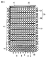
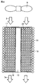
図20~図23を参照して、本発明に基づく実施の形態8における調湿装置について説明する。本実施の形態における調湿装置は、ヒータとして外周に設けられた外周ヒータ31を備えている。
図20~図23を参照して、本発明に基づく実施の形態8における調湿装置について説明する。本実施の形態における調湿装置は、ヒータとして外周に設けられた外周ヒータ31を備えている。
本実施の形態における調湿装置においては、通路筐体19は筒形であり、中心軸に沿って粒子群20を収容しない柱状空洞13を有し、ヒータは、粒子群20に外周から内周に向かって熱を加えるように通路筐体19の外周に沿って配置された外周ヒータ31を含む。柱状空洞13の内面を規定する壁材は網状となっている。
除湿の工程においては、図20に示すように、送風ファン9によって空気入口17から湿った空気3が通路筐体19の内部に送り込まれる。空気3は、通路筐体19の内部かつ柱状空洞13の外側に配置された粒子群20の隙間を通過することによって除湿され、除湿済の空気3eとして空気出口18から出ていく。
このように空気3の除湿を続けた結果、ほぼ全ての粒子がある程度以上の水分を吸収(収着)した状態になる。その状態を図21に示す。図21に示した状態であっても、必ずしも各粒子が飽和状態であるとは限らない。
次に、再生の工程について説明する。図22に示すように、上端から下端までの全区間にわたって外周ヒータ31を一斉にONにする。こうすることにより、外周面近傍にある粒子から順に昇温する。昇温した粒子は第2の状態に変化し、蓄えていた水分が放出される。粒子から放出された水分は、より内側にある粒子によって吸収(収着)されるか、または、粒子同士の隙間を通って内側に移動する。外周寄りから内周寄りに向かってこの現象が繰り返されることにより、図23に示すように、柱状空洞13の近傍に水が集まるようになる。さらに、いずれの粒子にも吸収(収着)されなくなって溢れた水5は、柱状空洞13の内面からにじみ出て、重力に従って下方へと落下する。
本実施の形態では、通路筐体19の中に柱状空洞13を有しているので、ヒータを部分ごとに順にONにするように制御するための機構が不要である。本実施の形態では、外周に設けられたヒータの全てをONにするだけで、水を柱状空洞へ向かって徐々に導くことができ、効率良く排出することができる。したがって、吸湿率の小さな吸湿材料を用いた場合であっても、効率的に水の回収が可能となる。
本実施の形態においても、上端から下端までのヒータの全てを一斉にONにする代わりに、ヒータを上から1つずつ順にONとしていく操作、あるいは、ヒータをいくつかのブロックに分けて上から1ブロックごとに順次ONとしていく操作を行なってもよい。
なお、高分子ゲル吸湿材料を主材料とする粒子群20だけを多数積層した場合、熱伝導が遅くなるおそれもある。そこで、ヒータからの熱の伝導を促進する目的で、高分子ゲル吸湿材料よりも熱伝導率が高い適当な材料、すなわちたとえば金属、樹脂、その他による部材を筐体の外周から中心側に向けて延在するように配置してもよい。ここで用いる材料が金属である場合、その金属の種類としては、たとえばアルミニウム、ステンレスなどが考えられる。特にアルミニウムは熱伝導率が高いので好ましい。筐体の外周から中心側に向けて配置する際には、外周から中心側に向かって枝が複数本それぞれ延在する櫛形の配置が考えられる。櫛形に限らず、さまざまな形状が採用可能である。
(実施の形態9)
図24~図26を参照して、本発明に基づく実施の形態9における除湿機について説明する。本実施の形態における除湿機501を前から見たところを図24に示し、後ろから見たところを図25に示す。除湿機501の前面513においては、下部に吹出口511a、上部に吹出口511bが設けられている。背面514には吸気口が設けられており、フィルタ512が吸気口を覆っている。
図24~図26を参照して、本発明に基づく実施の形態9における除湿機について説明する。本実施の形態における除湿機501を前から見たところを図24に示し、後ろから見たところを図25に示す。除湿機501の前面513においては、下部に吹出口511a、上部に吹出口511bが設けられている。背面514には吸気口が設けられており、フィルタ512が吸気口を覆っている。
図24におけるXXVI-XXVI線に関する矢視断面図を図26に示す。背面514の内側には、下部に配置された第1吸気ファン516と、上部に配置された第2吸気ファン517とが配置されている。筐体の内部空間は結露板518によって上下に隔てられている。結露板518の背面514側の端部は下に向かって曲がっている。結露板518の下側に高分子吸湿材520が配置されている。高分子吸湿材520は、実施の形態1~8で説明した考え方を適用して、粒子群20を保持したものである。図では高分子吸湿材520は多孔質のブロックであるように表示されているがこれはあくまで一例であってブロックとは限らない。高分子吸湿材520においては、実施の形態1~8で説明したように空気が上から下に向かって通過するものではなく、空気が横方向に通過するものである。したがって、粒子群20の配列も、実施の形態1~8で説明したものに比べて方向が90°異なる。
高分子吸湿材520は台525に載せられている。台525の下側には熱源521が配置されている。熱源521は台525を介して高分子吸湿材520を下方から加熱することができるように配置されている。除湿機501の最下部には水を受けて溜めるためのタンク515が配置されている。
除湿工程においては、熱源521および第2吸気ファン517はOFFとなっている状態で、第1吸気ファン516がONとなる。第1吸気ファン516によって外部の空気3が筐体内部の下部空間に導かれる。空気3は、高分子吸湿材520を通過することによって除湿され、空気3eとなって前面511の下側の吹出口511aから放出される。
再生工程においては、第1吸気ファン516はOFFとなり、熱源521および第2吸気ファン517がONとなる。熱源521によって高分子吸湿材520が加熱され、高分子吸湿材520から水分が放出される。液体状態でにじみ出てきた水は重力によってタンク515に導かれる。気体状態で放出された水分すなわち水蒸気6は、結露板518の下面に触れる。結露板518の上側では、第2吸気ファン517によって外部から導かれた空気3が結露板518の上面を冷やしながら通過し、前面513の上側の吹出口511bから出て行く。結露板518の下面に触れた水蒸気6は結露板518によって冷やされ、結露し、液体状態の水5となる。結露板518の一方の端は傾いているので、この部分に付着している水5は傾斜によって結露板518の下端に誘導され、落下し、タンク515に受けられる。
図26では結露板518の前面513寄りの部分は水平に延在しているように表示されているが、実際にはこの部分も、背面514側に近づくにつれて下がるように傾斜していることが好ましい。
本実施の形態では、高分子吸湿材520から水蒸気として放出された水分も結露板518の作用によって結露させて液体の水として回収することができる。
(実施の形態10)
図27~図29を参照して、本発明に基づく実施の形態10における除湿機について説明する。本実施の形態における除湿機502を一方の側から見たところを図27に示し、他方の側から見たところを図28に示す。図28に示すように、下部に吹出口511が設けられている。吹出口511と同じ側の上部には吸気口が設けられており、この吸気口をフィルタ512が覆っている。
図27~図29を参照して、本発明に基づく実施の形態10における除湿機について説明する。本実施の形態における除湿機502を一方の側から見たところを図27に示し、他方の側から見たところを図28に示す。図28に示すように、下部に吹出口511が設けられている。吹出口511と同じ側の上部には吸気口が設けられており、この吸気口をフィルタ512が覆っている。
図27におけるXXIX-XXIX線に関する矢視断面図を図29に示す。除湿機502においては、1ヶ所に共通吸気ファン519が設けられている。筐体の内部空間を上下に隔てるように結露板518iが設けられている。結露板518iの下側に高分子吸湿材520が配置されている。除湿機502の最下部には水を受けて溜めるためのタンク515が配置されている。結露板518iの上側空間と下側空間とをつなぐ通路に熱源522が配置されている。
除湿工程においては、熱源522はOFFの状態で、共通吸気ファン519がONとなる。共通吸気ファン519によって外部から空気3が筐体内に導かれる。空気3は、結露板518iの上側空間を通過して下側空間に回り込み、高分子吸湿材520を通過する。空気3は、高分子吸湿材520を通過することにより除湿され、空気3eとなって吹出口511から外部に放出される。
再生工程においては、熱源522がONの状態で、共通吸気ファン519がONとなる。共通吸気ファン519によって外部から空気3が筐体内に導かれる。空気3は熱源522によって温められた状態で、高分子吸湿材520を通過するので、高分子吸湿材520に含まれる粒子群は温度が上がり、第2の状態すなわち疎水性の状態となる。高分子吸湿材520から液体状態で放出された水5は、重力で落下し、タンク515に受けられる。高分子吸湿材520から気体状態で放出された水すなわち水蒸気6は、結露板518iの傾斜部分の下面に触れる。結露板518iの傾斜部分の上面には共通吸気ファン519によって外部から筐体内に導かれた空気3の一部が分岐して当たっているので、結露板518iの傾斜部分は冷却される。水蒸気6は結露板518iによって冷却され、結露し、液体状態の水5となる。結露板518iの傾斜部分の下面に付着している水5は重力によって下方へ導かれ、タンク515に受けられる。
本実施の形態では、高分子吸湿材520から水蒸気として放出された水分も結露板518iの作用によって結露させて液体の水として回収することができる。本実施の形態では、除湿時と再生時の両方で同一の共通吸気ファン519を兼用する構造となっているので、ファンの設置台数を少なく抑えることができる。
(実施の形態11)
図30~図33を参照して、本発明に基づく実施の形態11における除湿機について説明する。本実施の形態における除湿機503を前から見たところを図30に示し、後ろから見たところを図31に示す。除湿機501の前面513においては、下部に吹出口511a、上部に吹出口511bが設けられている。背面514には吸気口が設けられており、フィルタ512が吸気口を覆っている。
図30~図33を参照して、本発明に基づく実施の形態11における除湿機について説明する。本実施の形態における除湿機503を前から見たところを図30に示し、後ろから見たところを図31に示す。除湿機501の前面513においては、下部に吹出口511a、上部に吹出口511bが設けられている。背面514には吸気口が設けられており、フィルタ512が吸気口を覆っている。
図30におけるXXXII-XXXII線に関する矢視断面図を図32に示す。背面514の内側の下部の1ヶ所に共通吸気ファン519が設けられている。筐体の内部空間は結露板518jによって上下に隔てられている。結露板518jは背面514側に近づくにつれて下がるように湾曲している。結露板518jは筐体内で上下に平行移動できるようになっている。結露板518jの下側には、実施の形態9で説明したのと同様に高分子吸湿材520が配置されている。高分子吸湿材520が台525に載せられている点、熱源521およびタンク515が配置されている点などは、実施の形態9で説明したのと同様である。
除湿工程においては、結露板518jは図32に示すように高い位置に配置され、熱源521はOFFとなっている状態で、共通吸気ファン519がONとなる。共通吸気ファン519によって外部の空気3が筐体内部の下部空間に導かれる。空気3は、高分子吸湿材520を通過することによって除湿され、空気3eとなって前面511の下側の吹出口511aから放出される。
再生工程においては、図32において矢印91で示すように結露板518jが下方に移動し、図33に示すようになる。すなわち、結露板518jは低い位置に配置される。この状態で、熱源521および共通吸気ファン519がONとなる。熱源521によって高分子吸湿材520が加熱され、高分子吸湿材520から水分が放出される。液体状態でにじみ出てきた水は重力によってタンク515に導かれる。気体状態で放出された水分すなわち水蒸気6は、結露板518jの下面に触れる。結露板518jの上側では、共通吸気ファン519によって外部から導かれた空気3が結露板518jの上面を冷やしながら通過し、前面513の上側の吹出口511bから出て行く。結露板518jの下面に触れた水蒸気6は結露板518jによって冷やされ、結露し、液体状態の水5となる。結露板518jは湾曲しているので、結露板518jに付着している水5は傾斜によって結露板518jの下端に誘導され、落下し、タンク515に受けられる。
本実施の形態においても実施の形態10と同様の効果を得ることができる。本実施の形態では、結露板518jが移動することによって空気の通り道を明確に切り替えることができるので、効率良く作動することができる。
(付記3-1)
水分を吸収(収着)しうる第1の状態と、前記第1の状態のときに吸収(収着)した水分を放出する第2の状態とを有し、一定温度以上になると前記第1の状態から前記第2の状態へと変化し、かつ、前記一定温度以上ではなくなったときには前記第1の状態に戻る性質を有する高分子ゲル吸湿材料を主材料とする吸湿材と、
前記第1の状態のときに前記吸湿材に外気を誘導して当てる第1の送風ファンと、
前記第2の状態のときに前記吸湿材から放出される水蒸気を受ける位置に配置された結露板と、
前記結露板の前記水蒸気を受ける側の面とは反対側の面に風を当てることができる第2の送風ファンとを備える、除湿装置。
水分を吸収(収着)しうる第1の状態と、前記第1の状態のときに吸収(収着)した水分を放出する第2の状態とを有し、一定温度以上になると前記第1の状態から前記第2の状態へと変化し、かつ、前記一定温度以上ではなくなったときには前記第1の状態に戻る性質を有する高分子ゲル吸湿材料を主材料とする吸湿材と、
前記第1の状態のときに前記吸湿材に外気を誘導して当てる第1の送風ファンと、
前記第2の状態のときに前記吸湿材から放出される水蒸気を受ける位置に配置された結露板と、
前記結露板の前記水蒸気を受ける側の面とは反対側の面に風を当てることができる第2の送風ファンとを備える、除湿装置。
(付記3-2)
前記第1の送風ファンは前記第2の送風ファンを兼ねている、付記3-1に記載の除湿装置。
前記第1の送風ファンは前記第2の送風ファンを兼ねている、付記3-1に記載の除湿装置。
なお、今回開示した上記実施の形態はすべての点で例示であって制限的なものではない。本発明の範囲は上記した説明ではなくて請求の範囲によって示され、請求の範囲と均等の意味および範囲内でのすべての変更を含むものである。
本発明は、調湿装置に利用することができる。
2a,2b 粒子、2c 大粒子、2d 小粒子、3,3e 空気、5 水、6 水蒸気、9 送風ファン、10 電源、11 通気領域、12 非通気領域、13 柱状空洞、14 中心軸、15 制御機構、17 空気入口、18 空気出口、19 通路筐体、20 粒子群、21 第1粒子群、22 第2粒子群、23 第3粒子群、30 ヒータ、31 外周ヒータ、32 平板ヒータ、41 加熱領域、42 非加熱領域、91 矢印、101,102,103,104,105 調湿装置、501,502,503 除湿機、511,511a,511b 吹出口、512 フィルタ、513 前面、514 背面、515 タンク、516 第1吸気ファン、517 第2吸気ファン、518,518i,518j 結露板、519 共通吸気ファン、520 高分子吸収材、521,522 熱源、525 台。
Claims (5)
- 水分を吸収しうる第1の状態と、前記第1の状態のときに吸収した水分を放出する第2の状態とを有し、環境条件が満たされると前記第1の状態から前記第2の状態へと変化し、かつ、前記環境条件が満たされなくなったときには前記第1の状態に戻る性質を有する高分子ゲル吸湿材料を主材料とする粒子群と、
前記粒子群を収容する通路筐体とを備え、
前記通路筐体は、外部から空気を取り込む空気入口と、前記空気入口から取り込まれて前記粒子群の隙間を通過した空気を排出する空気出口とを有し、
前記粒子群は、第1の径を有する第1粒子群と、前記第1の径より小さな第2の径を有する第2粒子群とを含み、
前記通路筐体内において、前記第1粒子群は前記第2粒子群よりも前記空気入口寄りに配置されている、調湿装置。 - 前記環境条件は一定以上の温度であることであり、前記通路筐体には、前記粒子群に熱を加えるためのヒータが設けられている、請求項1に記載の調湿装置。
- 前記通路筐体は、前記空気入口から前記空気出口に向かう方向に並ぶ複数の区画に分かれており、前記粒子群は前記複数の区画に分けて収容されており、前記ヒータは、前記複数の区画の各々に個別に熱を加えるように前記通路筐体の外周に沿って配置された外周ヒータを含む、請求項2に記載の調湿装置。
- 前記複数の区画の各々には、異なる粒子径の前記粒子群が収容されており、各区画は、前記空気入口側から前記空気出口側に向かって粒子径が順に小さくなるように配列されており、前記空気入口側の区画から前記空気出口側の区画へと順に加熱していくように前記ヒータを制御する制御機構を備える、請求項1から3のいずれかに記載の調湿装置。
- 前記通路筐体は筒形であり、中心軸に沿って前記粒子群を収容しない柱状空洞を有し、前記ヒータは、前記粒子群に外周から内周に向かって熱を加えるように前記通路筐体の外周に沿って配置された外周ヒータを含む、請求項2から4のいずれかに記載の調湿装置。
Priority Applications (2)
| Application Number | Priority Date | Filing Date | Title |
|---|---|---|---|
| JP2016517827A JP6266100B2 (ja) | 2014-05-09 | 2015-02-27 | 調湿装置 |
| CN201580011406.2A CN106062484B (zh) | 2014-05-09 | 2015-02-27 | 湿度调节装置 |
Applications Claiming Priority (2)
| Application Number | Priority Date | Filing Date | Title |
|---|---|---|---|
| JP2014097526 | 2014-05-09 | ||
| JP2014-097526 | 2014-05-09 |
Publications (1)
| Publication Number | Publication Date |
|---|---|
| WO2015170501A1 true WO2015170501A1 (ja) | 2015-11-12 |
Family
ID=54392355
Family Applications (1)
| Application Number | Title | Priority Date | Filing Date |
|---|---|---|---|
| PCT/JP2015/055778 Ceased WO2015170501A1 (ja) | 2014-05-09 | 2015-02-27 | 調湿装置 |
Country Status (3)
| Country | Link |
|---|---|
| JP (1) | JP6266100B2 (ja) |
| CN (1) | CN106062484B (ja) |
| WO (1) | WO2015170501A1 (ja) |
Cited By (7)
| Publication number | Priority date | Publication date | Assignee | Title |
|---|---|---|---|---|
| JP2017138078A (ja) * | 2016-02-05 | 2017-08-10 | ダイキン工業株式会社 | 除湿システム |
| WO2019135352A1 (ja) * | 2018-01-04 | 2019-07-11 | シャープ株式会社 | 調湿装置および調湿方法 |
| KR20190083445A (ko) * | 2018-01-04 | 2019-07-12 | 한국기계연구원 | 멤브레인 제습모듈 및 이를 이용한 제습장치 |
| WO2022039149A1 (ja) * | 2020-08-18 | 2022-02-24 | シャープ株式会社 | 水集積装置、及び水集積方法 |
| CN115485520A (zh) * | 2020-05-14 | 2022-12-16 | 松下知识产权经营株式会社 | 干燥机、干燥方法及除湿过滤器 |
| CN117529249A (zh) * | 2021-07-26 | 2024-02-06 | 夏普株式会社 | 非加热型香味成分释放装置、非加热型香味吸取器及非加热型香味缓释装置 |
| CN119309255A (zh) * | 2024-10-14 | 2025-01-14 | 轮特环境科技无锡有限公司 | 一种基于生物医药研发的室内湿度保持除湿机 |
Families Citing this family (1)
| Publication number | Priority date | Publication date | Assignee | Title |
|---|---|---|---|---|
| CN114442688A (zh) * | 2022-01-21 | 2022-05-06 | 深圳大成智能电气科技有限公司 | 一种柜内湿度管理装置及湿度管理方法 |
Citations (4)
| Publication number | Priority date | Publication date | Assignee | Title |
|---|---|---|---|---|
| JPH0727382A (ja) * | 1993-07-09 | 1995-01-27 | Matsushita Electric Ind Co Ltd | 除加湿装置 |
| JPH0796025A (ja) * | 1993-08-04 | 1995-04-11 | Astec Internatl:Kk | 空気清浄化装置及び空気清浄化方法 |
| JPH11267445A (ja) * | 1998-03-25 | 1999-10-05 | Daikin Ind Ltd | 脱臭デバイスとこれを備えた脱臭機及び空気調和機 |
| JP2003042502A (ja) * | 2001-07-30 | 2003-02-13 | Panahome Corp | 換気装置 |
Family Cites Families (3)
| Publication number | Priority date | Publication date | Assignee | Title |
|---|---|---|---|---|
| SE383777B (sv) * | 1973-07-18 | 1976-03-29 | Munters Ab Carl | Sett och anordning for kylning av luft |
| NL1021812C1 (nl) * | 2002-04-26 | 2003-10-28 | Oxycell Holding Bv | Dauwpuntskoeler. |
| CN103084156A (zh) * | 2011-11-04 | 2013-05-08 | 财团法人工业技术研究院 | 除湿装置及其通电脱附装置 |
-
2015
- 2015-02-27 JP JP2016517827A patent/JP6266100B2/ja active Active
- 2015-02-27 CN CN201580011406.2A patent/CN106062484B/zh active Active
- 2015-02-27 WO PCT/JP2015/055778 patent/WO2015170501A1/ja not_active Ceased
Patent Citations (4)
| Publication number | Priority date | Publication date | Assignee | Title |
|---|---|---|---|---|
| JPH0727382A (ja) * | 1993-07-09 | 1995-01-27 | Matsushita Electric Ind Co Ltd | 除加湿装置 |
| JPH0796025A (ja) * | 1993-08-04 | 1995-04-11 | Astec Internatl:Kk | 空気清浄化装置及び空気清浄化方法 |
| JPH11267445A (ja) * | 1998-03-25 | 1999-10-05 | Daikin Ind Ltd | 脱臭デバイスとこれを備えた脱臭機及び空気調和機 |
| JP2003042502A (ja) * | 2001-07-30 | 2003-02-13 | Panahome Corp | 換気装置 |
Cited By (11)
| Publication number | Priority date | Publication date | Assignee | Title |
|---|---|---|---|---|
| JP2017138078A (ja) * | 2016-02-05 | 2017-08-10 | ダイキン工業株式会社 | 除湿システム |
| WO2019135352A1 (ja) * | 2018-01-04 | 2019-07-11 | シャープ株式会社 | 調湿装置および調湿方法 |
| KR20190083445A (ko) * | 2018-01-04 | 2019-07-12 | 한국기계연구원 | 멤브레인 제습모듈 및 이를 이용한 제습장치 |
| KR102009774B1 (ko) * | 2018-01-04 | 2019-08-12 | 한국기계연구원 | 멤브레인 제습모듈 및 이를 이용한 제습장치 |
| CN115485520A (zh) * | 2020-05-14 | 2022-12-16 | 松下知识产权经营株式会社 | 干燥机、干燥方法及除湿过滤器 |
| WO2022039149A1 (ja) * | 2020-08-18 | 2022-02-24 | シャープ株式会社 | 水集積装置、及び水集積方法 |
| JPWO2022039149A1 (ja) * | 2020-08-18 | 2022-02-24 | ||
| US12521672B2 (en) | 2020-08-18 | 2026-01-13 | Sharp Kabushiki Kaisha | Water collecting apparatus and water collecting method |
| JP7851063B2 (ja) | 2020-08-18 | 2026-04-24 | シャープ株式会社 | 水集積装置、及び水集積方法 |
| CN117529249A (zh) * | 2021-07-26 | 2024-02-06 | 夏普株式会社 | 非加热型香味成分释放装置、非加热型香味吸取器及非加热型香味缓释装置 |
| CN119309255A (zh) * | 2024-10-14 | 2025-01-14 | 轮特环境科技无锡有限公司 | 一种基于生物医药研发的室内湿度保持除湿机 |
Also Published As
| Publication number | Publication date |
|---|---|
| CN106062484B (zh) | 2019-02-15 |
| JP6266100B2 (ja) | 2018-01-24 |
| JPWO2015170501A1 (ja) | 2017-04-20 |
| CN106062484A (zh) | 2016-10-26 |
Similar Documents
| Publication | Publication Date | Title |
|---|---|---|
| JP6266100B2 (ja) | 調湿装置 | |
| CN106659968B (zh) | 除湿装置 | |
| JP2016077967A (ja) | 吸湿材、除湿装置及び除湿方法 | |
| JP2016221445A (ja) | 除湿装置及び除湿方法 | |
| JP2011121516A (ja) | 電気自動車用防曇・空調システム | |
| JP2018202417A (ja) | 除湿機および製水機 | |
| EP3043888B1 (en) | Water extracting device | |
| CN103140273B (zh) | 除湿器和除湿方法 | |
| JP2012166128A5 (ja) | ||
| CN204012330U (zh) | 高压柜洁净干空气交换系统 | |
| JP2011143358A (ja) | 吸湿フィルタおよび加湿装置 | |
| CN102327728A (zh) | 一种可再生除湿器 | |
| JP4529318B2 (ja) | 除湿デバイスと前記除湿デバイスを使用した冷風発生装置 | |
| JP5934009B2 (ja) | 冷房除湿システム | |
| JP5628607B2 (ja) | 空調システム | |
| JP2006026523A (ja) | 吸着器、および冷房装置 | |
| JP7674264B2 (ja) | 除湿装置 | |
| JP2001259417A (ja) | 空調装置用吸着材,吸湿素子および除湿方法 | |
| JP6443964B2 (ja) | 調湿ユニット | |
| JP2012183460A (ja) | 除湿体及びこれを備えたデシカント除湿装置 | |
| JP5844058B2 (ja) | 除湿体及びこれを備えたデシカント除湿装置 | |
| JP2006289258A (ja) | 除湿体及びこれを用いたデシカント空調装置 | |
| JP2012179559A (ja) | 除湿体及びこれを備えたデシカント除湿装置 | |
| CN103406000A (zh) | 利用低温不饱和空气进行除湿的方法和装置 | |
| JP6235392B2 (ja) | 冷房装置 |
Legal Events
| Date | Code | Title | Description |
|---|---|---|---|
| 121 | Ep: the epo has been informed by wipo that ep was designated in this application |
Ref document number: 15789624 Country of ref document: EP Kind code of ref document: A1 |
|
| ENP | Entry into the national phase |
Ref document number: 2016517827 Country of ref document: JP Kind code of ref document: A |
|
| NENP | Non-entry into the national phase |
Ref country code: DE |
|
| 122 | Ep: pct application non-entry in european phase |
Ref document number: 15789624 Country of ref document: EP Kind code of ref document: A1 |