WO2015156189A1 - スリングシート - Google Patents
スリングシート Download PDFInfo
- Publication number
- WO2015156189A1 WO2015156189A1 PCT/JP2015/060358 JP2015060358W WO2015156189A1 WO 2015156189 A1 WO2015156189 A1 WO 2015156189A1 JP 2015060358 W JP2015060358 W JP 2015060358W WO 2015156189 A1 WO2015156189 A1 WO 2015156189A1
- Authority
- WO
- WIPO (PCT)
- Prior art keywords
- transfer
- sheet
- seat body
- sling
- portions
- Prior art date
- Legal status (The legal status is an assumption and is not a legal conclusion. Google has not performed a legal analysis and makes no representation as to the accuracy of the status listed.)
- Ceased
Links
Images



Classifications
-
- A—HUMAN NECESSITIES
- A61—MEDICAL OR VETERINARY SCIENCE; HYGIENE
- A61G—TRANSPORT, PERSONAL CONVEYANCES, OR ACCOMMODATION SPECIALLY ADAPTED FOR PATIENTS OR DISABLED PERSONS; OPERATING TABLES OR CHAIRS; CHAIRS FOR DENTISTRY; FUNERAL DEVICES
- A61G7/00—Beds specially adapted for nursing; Devices for lifting patients or disabled persons
- A61G7/10—Devices for lifting patients or disabled persons, e.g. special adaptations of hoists thereto
Definitions
- the disclosed embodiment relates to a sling sheet.
- Patent Document 1 describes a nursing sling that is used when a care receiver is lifted and moved.
- This care sling is composed of a seat portion on which a care recipient is placed and a hanging strap sewn in a loop shape at substantially four corners of the seat portion.
- the care receiver When the care receiver is transferred by the transfer assist device using the above-described conventional sling sheet, the care receiver's buttocks fall from the seat body, and the buttocks and the hip joint may be pressed or tightened. For this reason, in such a sling seat, improving the comfort of the cared person at the time of transfer is desired.
- This invention is made in view of such a problem, and it aims at providing the sling seat which can improve the comfort of the care receiver at the time of transfer.
- a first hanging portion provided with a first joint portion joined in the vicinity of a portion of the seat body corresponding to the sciatic tubercle of the cared person, and a first attachment / detachment portion attached to and detached from the transfer assist device.
- a sling sheet is applied.
- a sling sheet used in a transfer assist device for assisting transfer of a cared person, the seat body on which the cared person is placed, and the seat body in the seat body.
- a fourth joining portion joined to a position spaced a predetermined distance from the center position in the direction corresponding to the width direction of the care recipient, and a fourth attaching / detaching portion attached to and detached from the transfer assist device.
- a sling sheet having a fourth hanging portion is applied.
- a sling seat for use in a transfer assist device for assisting transfer of a cared person, the seated posture of the cared person's buttocks placed on the seat body.
- a sling sheet having means for suppressing sagging is applied.
- the comfort of the cared person at the time of transfer can be improved.
- the sling sheet 1 is a transfer assist device 100 (see FIG. 2, which will be described later) for assisting the transfer (also referred to as “transfer operation”) of a cared person 50 (see FIG. 2, which will be described later). Used for.
- “Transfer” refers to the movement from the current position / posture to another position / posture.
- a sitting posture also referred to as a “sitting posture”
- a lying posture also referred to as a “posture posture”
- a certain position for example, a bed
- another position for example, a wheelchair
- the sling sheet 1 includes a seat body 2 on which the care recipient 50 is placed, and a plurality of suspension portions 4, 6, and 8 for suspending the seat body 2 on the transfer assist device 100.
- the sheet body 2 is configured to have a shape and size that can place almost the entire care receiver 50 by cutting and stitching one or more cloths.
- the material / material of the cloth constituting the seat body 2 is not particularly limited as long as it is a material / material suitable for supporting the care recipient 50.
- the sheet main body 2 includes a main body portion 10 and two extending portions 12 and 12.
- the main body portion 10 has a substantially rectangular developed shape, and is a portion for mainly supporting a portion on the upper side from the collar portion 52 (see FIG. 4 described later) of the care receiver 50 placed on the seat main body 2. .
- a first support portion 14 for mainly supporting the shoulder portion 56 is provided at a portion of the main body portion 10 corresponding to the shoulder portions 56 and 56 of the care receiver 50 (see FIG. 2 described later). It has been.
- part corresponding to the shoulder part 56 in the main-body part 10 means the site
- Each first support portion 14 is three-dimensionally formed by cutting and stitching a cloth so as to have a three-dimensional shape (three-dimensional structure) along the shape of the shoulder portion 56.
- each 1st support part 14 does not necessarily need to be three-dimensionally molded as described above.
- a second support portion 16 for mainly supporting the head portion 58 is provided at a portion of the main body portion 10 corresponding to the head portion 58 (see FIG. 2 described later) of the care recipient 50.
- part corresponding to the head 58 in the main-body part 10 is a site
- the extending portions 12, 12 are bifurcated from the vicinity of the portion corresponding to the collar portion 52 of the main body portion 10 to the side corresponding to the leg portions 55, 55 (see FIG. 2 described later) of the care receiver 50, that is, the lower side.
- This is a portion for mainly supporting the leg portions 55 and 55 of the cared person 50 that is extended in a shape and placed on the seat body 2.
- part corresponding to the collar part 52 in the main-body part 10 means the site
- Each of these extended portions 12 has a shape curved in a direction approaching the other extended portion 12 so as to intersect with the other extended portion 12 when the sheet body 2 is planar (deployed shape). Yes. Specifically, each extending portion 12 crosses the other extending portion 12 at a portion 12b corresponding to the lower part 54 (see FIG. 4 described later) of the care receiver 50 in the extending portion 12. Is formed.
- part 12b corresponding to the thigh lower part 54 in the extension part 12 is located between the base of the extension part 12, and the front-end
- the extending portions 12 and 12 extending from the main body portion 10 in a bifurcated manner are not always necessary, and the main body portion having a substantially rectangular shape is a substantially entire body (head) of the care recipient 50. (From the portion 58 to the leg portions 55, 55) may be supported.
- a cushion material 20 having cushioning properties is installed at a portion of each extending portion 12 that intersects the other extending portion 12, that is, a portion 12b corresponding to the lower thigh 54. Thereby, the lower part 54 of the care receiver 50 can be protected.
- the material / material of the cushion material 20 is not particularly limited as long as it is a material / material having cushioning properties.
- the cushion material 20 is installed only in one of the two extending portions 12 and 12 (for example, the extending portion 12 intersecting on the front side), or the cushion material 20 is cushioned in either of the extending portions 12 and 12. The material 20 may not be installed.
- the accommodating part 18 which can insert / extract the cushion material 20 is provided in the site
- performance such as the hardness of the cushion material 20 used according to the symptom and preference of the care receiver 50, can be changed.
- the cushion material 20 is not necessarily accommodated in the accommodating portion 18.
- the cushion material 20 is joined to the surface or the inside of the portion 12 b corresponding to the lower thigh 54 in the extended portion 12, or the portion 12 b itself is the cushion material. It may be.
- the surface 2a (hereinafter also referred to as “surface 2a” as appropriate) of the seat body 2 on which the care receiver 50 is placed corresponds to the width direction of the care receiver 50.
- a first display unit 22 that displays the center position of the direction is provided.
- the direction corresponding to the width direction of the cared person 50 refers to a direction that can be parallel to the width direction of the cared person 50 placed on the seat body 2 at the time of transfer, that is, a horizontal direction (described later). (See FIG.
- the first display portion 22 is substantially linear in a color different from the surface 2a from one end (upper end in this example) to the other end (lower end in this example) of the center portion in the left-right direction of the main body 10 portion on the surface 2a. Is formed. Thereby, when placing the cared person 50 on the seat body 2, the spine position of the cared person 50 and the center position in the left-right direction of the seat body 2 can be easily matched.
- the aspect of the 1st display part 22 will not be limited to said aspect, if it is an aspect which can display the center position of the left-right direction.
- the first display unit 22 may be provided on a surface opposite to the front surface 2a of the sheet body 2 (hereinafter also referred to as “rear surface” as appropriate). Or the 1st display part 22 does not need to be provided in either the surface 2a and the back surface of the sheet
- FIG. 1st display part 22 does not need to be provided in either the surface 2a and the back surface of the sheet
- the surface 2a is provided with a second display portion 24 for displaying the base end positions of the extending portions 12, 12.
- the 2nd display part 24 is formed in the lower end of the center position of the left-right direction of the main-body part 10 part in the surface 2a.
- the collar part 52 of the cared person 50 can be easily placed at an appropriate position.
- the aspect of the 2nd display part 24 will not be limited to said aspect, if the aspect which can display the base end position of the extending parts 12 and 12 is displayable.
- the second display unit 24 may be provided on the back surface of the sheet body 2. Or the 2nd display part 24 does not need to be provided in either the surface 2a of the sheet
- the suspension part 4 (corresponding to an example of the first suspension part and the fourth suspension part) is joined to both the left and right sides of the seat body 2.
- the pair of hanging portions 4, 4 are formed so as to have a symmetrical shape in the left-right direction in a state where they are respectively joined to the left and right sides of the seat body 2.
- Each hanging portion 4 has a hanging strap 40 and a reinforcing cloth 42.
- the hanging strap 40 is attached to the transfer assisting device 100 by joining both end portions 40a and 40a to one end portion 42a of the reinforcing cloth 42 in a looped state at the center position in the longitudinal direction.
- a possible detachable portion 43 (corresponding to an example of the first detachable portion and the fourth detachable portion) is formed.
- the attaching / detaching portion 43 includes an engaged portion 44 that can be attached to and detached from the engaging portions 104 and 107 (see FIG. 2 and the like described later) of the transfer assist device 100.
- the locked portion 44 a folded portion 40b of the hanging strap 40, and a plurality (not shown) of which one end and the other end are respectively joined to one side and the other side sandwiching the folded portion 40b of the hanging strap 40.
- four) connecting cloths 41 are provided.
- the plurality of locked portions 44 arranged at different positions in the longitudinal direction of the detachable portion 43 have different colors.
- the plurality of locked portions 44 may be the same color. Further, the locked portion 44 may be only one of the folded portions 40b.
- the reinforcing cloth 42 has both ends 40a, 40a of the hanging strap 40 joined to the one end 42a, and the other end 42b in the left-right direction on the back surface (or the front surface 2a) of the sheet body 2. It is joined at a position spaced a predetermined distance from the center position in the direction. Note that the position in the seat body 2 that is a predetermined distance away from the center position in the left-right direction is the vicinity of the site corresponding to the sciatic nodule 53 (see FIG. 4 described later) of the care recipient 50.
- the part corresponding to the sciatic nodule 53 in the seat body 2 refers to a part that can be located immediately below the sciatic nodule 53 of the cared person 50 placed on the seat main body 2 at the time of transfer (see below-described figure). 4 etc.). That is, the other end portion 42b of the reinforcing cloth 42 joined to the vicinity of the portion corresponding to the sciatic nodule 53 on the back surface of the seat body 2 corresponds to an example of the first joint portion and the fourth joint portion.
- the said hanging strap 40 may be joined to the site
- each suspension part 4 is a structure provided with the attachment part joined to the site
- the configuration is not limited.
- the hanging part 6 (corresponding to an example of the second hanging part) is joined to the tip parts 12a and 12a of the extending parts 12 and 12, respectively.
- the pair of hanging portions 6 and 6 are formed so as to have a symmetrical shape in the left-right direction in a state where they are joined to the tip portions 12a and 12a.
- Each hanging portion 6 is constituted by a hanging strap 60.
- the hanging strap 60 is folded at the center position in the longitudinal direction to form a loop shape, and both end portions 60a, 60a are formed on the distal end portion 12a of the extending portion 12 (in this example, from the back side of the sheet body 2).
- An attachment / detachment portion 63 (corresponding to an example of a second attachment / detachment portion) that can be attached to and detached from the transfer assist device 100 is formed by being joined. That is, both end portions 60a and 60a of the hanging strap 60 joined to the distal end portion 12a of the extending portion 12 correspond to an example of the second joining portion.
- the hanging strap 60 may be coupled to the distal end portion 12a of the extending portion 12 via a reinforcing cloth.
- the attaching / detaching portion 63 includes an engaging portion 64 that can be attached to and detached from the engaging portions 105 and 108 (see FIG. 2 and the like described later) of the transfer assist device 100.
- the locked portion 64 a plurality of folded portions 60 b of the hanging strap 60, and one end and the other end joined to one side and the other side sandwiching the folded portion 60 b of the hanging strap 60 (illustrated). In the example, three) connecting cloths 61 are provided.
- the plurality of locked portions 64 arranged at different positions in the longitudinal direction of the detachable portion 63 have different colors.
- the plurality of locked portions 64 may be the same color as each other. Further, the locked portion 64 may be only one of the folded portions 60b.
- each suspension part 6 is a structure provided with the junction part joined to the front-end
- the suspension part 8 (corresponding to an example of a third suspension part) is joined to the left and right sides of the second support part 16 respectively.
- the pair of hanging portions 8, 8 are formed so as to have a symmetrical shape in the left-right direction in a state where they are joined to the left and right sides of the second support portion 16.
- Each hanging portion 8 is constituted by a hanging strap 80.
- the hanging strap 80 is folded at a central position in the longitudinal direction so as to have a loop shape, and both end portions 80a and 80a of the second support portion 16 in the direction corresponding to the height direction of the care recipient 50.
- the attachment / detachment part 83 (corresponding to an example of a third attachment / detachment part) that can be attached to and detached from the transfer assisting device 100 is formed by being branched to (in this example, from the back side of the seat body 2).
- the head 58 of the care receiver 50 can be supported in a planar shape by the two support portions 16.
- the direction corresponding to the height direction of the cared person 50 means a direction parallel to the height direction of the cared person 50 placed on the seat body 2 at the time of transfer, that is, a vertical direction (described later). (See 2nd grade). That is, both end portions 80a and 80a of the hanging strap 80 that are branched and joined to the upper and lower ends of the second support portion 16 correspond to an example of a third joint portion.
- the hanging strap 80 may be branched and connected to the upper and lower ends of the second support portion 16 via a reinforcing cloth.
- the attaching / detaching portion 83 includes an engaged portion 84 that can be attached to and detached from the engaging portions 105 and 108 (see FIG. 2 and the like described later) of the transfer assist device 100.
- the locked portion 84 a folded portion 80b of the hanging strap 80, and one end and the other end joined to one side and the other side sandwiching the folded portion 80b of the hanging strap 80 (not shown).
- three connection cloths 81 are provided.
- the plurality of locked portions 84 arranged at different positions in the longitudinal direction of the detachable portion 83 have different colors.
- the plurality of locked portions 84 may be the same color as each other. Further, the locked portion 84 may be only one of the folded portions 80b.
- each suspension part 8 is a structure provided with the junction part branched and joined to the up-and-down both ends of the 2nd support part 16, and the attachment or detachment part attached to the transfer assistance apparatus 100, said structure It is not limited to.
- the configuration of the joint portion of each hanging portion 8 is not limited to the configuration in which the second support portion 16 is branched and joined to the upper and lower ends.
- the transfer assisting device 100 includes a center holder portion 102, a main body portion 101, a pair of arm members 103 and 103, and a pair of arm members 106 and 106.
- the center holder portion 102 is supported in a cantilever shape by the main body portion 101 so as to extend in the horizontal direction.
- the main body 101 has an elevating mechanism that elevates and lowers the central holder 102.
- the arm members 103, 103 are arranged in such a way that the central holder portion is positioned relative to one side in the circumferential direction of the central holder portion 102 (in this example, the front side) so as to rotate synchronously (together) with the central holder portion 102 as the central axis. They are connected while being separated in the extending direction of 102 (in this example, the left-right direction).
- Each of the arm members 103 is provided with two locking portions 104 and 105 configured by hook-shaped hooks.
- the locking portion 104 is provided at an intermediate position between the base end portion and the distal end portion of each arm member 103, and the locked portion 44 in the hanging portion 4 of the sling sheet 1 can be attached and detached. That is, when the cared person 50 is placed on the seat body 2 with the head 58 on the arm member 106 side and the legs 55 and 55 on the arm member 103 side, as shown in FIG. The locked portion 44 of the hanging portion 4 is not attached to the locking portion 104. On the other hand, although not particularly illustrated, when the cared person 50 is placed on the seat body 2 with the head 58 on the arm member 103 side and the legs 55 and 55 on the arm member 106 side, Any locked portion 44 of the hanging portion 4 is attached to the stop portion 104.
- the locking portion 105 is provided in the vicinity of the tip of each arm member 103, and the locked portion 44 in the hanging portion 6 of the sling sheet 1 or the locked portion 84 in the hanging portion 8 can be attached and detached. That is, when the cared person 50 is placed on the seat body 2 with the head 58 on the arm member 106 side and the legs 55 and 55 on the arm member 103 side, as shown in FIG.
- the locked portion 105 is mounted with any of the locked portions 64 of the hanging portion 6 (in the illustrated example, the folded portion 60b is mounted).
- any locked portion 84 of the hanging portion 8 is attached to the stop portion 105.
- the arm members 106, 106 are arranged in the left-right direction with respect to the other circumferential side of the central holder portion 102 (the rear side in this example) so as to rotate synchronously (together) with the central holder portion 102 as the central axis. They are connected while being separated.
- Each of the arm members 106 is provided with two locking portions 107 and 108 configured by hook-shaped hooks.
- the locking portion 107 is provided at an intermediate position between the base end portion and the distal end portion of each arm member 106, and the locked portion 44 in the hanging portion 4 of the sling sheet 1 can be attached and detached. That is, when the cared person 50 is placed on the seat body 2 with the head 58 on the arm member 106 side and the legs 55 and 55 on the arm member 103 side, as shown in FIG.
- the locked portion 107 is mounted with any locked portion 44 of the hanging portion 4 (in the illustrated example, the folded portion 40b is mounted).
- the locking portion 108 is provided in the vicinity of the distal end portion of each arm member 106, and the locked portion 44 in the hanging portion 6 of the sling sheet 1 or the locked portion 84 in the hanging portion 8 can be attached and detached. That is, when the cared person 50 is placed on the seat body 2 with the head 58 on the arm member 106 side and the legs 55 and 55 on the arm member 103 side, as shown in FIG.
- the locked portion 108 is mounted with any of the locked portions 84 of the hanging portion 8 (in the illustrated example, the folded portion 80b is mounted).
- any locked portion 64 of the hanging portion 6 is attached to the stop portion 108.
- the arm members 103 and 103 and the arm members 106 and 106 are respectively connected to the front side and the rear side of the central holder portion 102 so as to rotate independently from each other (separately).
- the transfer assisting device 100 the locked portions 44, 64, and 84 of the hanging portions 4, 6, and 8 joined to the seat body 2 on which the care recipient 50 is placed are locked by the corresponding locking portions.
- the care receiver 50 can be lifted (lifted) or lowered by lifting and lowering the central holder portion 102 and the arm members 103 and 106 connected thereto by the lifting mechanism.
- the posture of the cared person 50 can be changed by rotating the arm members 103 and 106 around the central holder part 102 with the cared person 50 lifted. It is.
- the structure of the transfer assistance apparatus 100 demonstrated above is an example to the last, and if it is a structure which can assist the care receiver 50's transfer using the sling sheet 1, it may be another structure. Needless to say.
- a caregiver (not shown) appropriately moves the cared person 50 lying on the bed B (in a lying position) on the bed B while the cared person 50 moves the seat body.
- the sling sheet 1 is laid on the bed B so as to be placed on the bed B.
- the caregiver places the cared person 50 on the surface 2a side of the seat body 2 while the center position (spine position) of the cared person 50 in the width direction is on the first display unit 22. It is preferable. Further, at this time, the caregiver has the head 58 at the position of the second support portion 16, the shoulder portions 56 at the positions of the first support portions 14, and the thigh lower portions 54 of the leg portions 55 are connected to the extended portions 12. , 12 is preferably placed on the seat body 2 while being positioned at a plane part where the parts 12 and 12 intersect (the part where the parts 12b and 12b overlap).
- the caregiver moves the transfer assisting device 100 to the vicinity of the bed B.
- the transfer assisting device 100 is in the vicinity of the bed B so that the arm member 103 is on the legs 55 and 55 side (the hanging part 6 side) and the arm member 106 is on the head 58 side (the hanging part 8 side). Placed in.
- the caregiver attaches the locked portion 44 (folded portion 40b in this example) of each hanging portion 4 to each locking portion 107, and the locked portion 64 of each hanging portion 6 (folded in this example).
- Portion 60b) is attached to each locking portion 105, and the above-mentioned locked portion 84 (folded portion 80b in this example) of each suspension portion 8 is attached to each locking portion 108.
- the sling sheet 1 on which the care receiver 50 is placed on the seat body 2 is suspended from the transfer assisting device 100 via the suspension portions 4, 6, and 8.
- the care receiver 50 is lifted when the central holder 102 is raised, and the posture of the care receiver 50 is moved when the arm members 103 and 106 are rotated. It is changed to a sitting posture (in this example, a sitting posture with the pelvis 51 upright) that matches the sitting shape of the wheelchair W (see FIG. 5 described later). Then, the caregiver moves the transfer assist device 100 in a state where the care receiver 50 in the sitting position is lifted toward the wheelchair W.
- a sitting posture in this example, a sitting posture with the pelvis 51 upright
- each of the extending portions 12 and 12 that support the lower thighs 54 and 54 of the leg portions 55 and 55 has a shape that is curved so as to approach each other so as to intersect with each other at the portions 12b and 12b.
- the lower thighs 54 and 54 are pulled up while being supported in a planar shape at the plane portion where the extended portions 12 and 12 intersect. Thereby, it can suppress that the cared person 50 causes the pain and discomfort of the lower thighs 54 and 54, and the abrasion of the skin.
- each hanging portion 4 is attached to the seat. Since it is joined in the vicinity of the site corresponding to the sciatic nodule 53 of the main body 2, the buttock 52 can be supported from the lower part of the sciatic nodule 53 that supports the body weight when the care recipient 50 in the sitting position is lifted or moved. Thereby, the fall of the collar part 52 of the care receiver 50 from the seat body 2 can be suppressed. That is, each hanging part 4 corresponds to an example of a unit that suppresses the drop of the buttocks of the care receiver in the sitting position placed on the seat body.
- the care holder 50 is lowered and the care receiver 50 is lowered by the lowering of the central holder portion 102. Sitting in W.
- the depression of the buttocks 52 from the seat body 2 can be suppressed, so that the cared person 50 can be prevented from taking the sitting posture in the pelvic backward tilted state, and the cared person 50 can be placed in the sitting position of the wheelchair W. It is possible to make the posture suitable for the shape. Thereby, the cared person 50 can be properly seated on the wheelchair W (for example, seated at a deep position of the wheelchair W).
- the transfer contents of the care recipient 50 performed by the transfer assisting device 100 using the sling sheet 1 described above are merely examples, and may be other contents.
- the present invention is applied to the case where the cared person 50 is lifted and moved after the cared person 50 is lifted, but the cared person 50 is moved after the cared person 50 is lifted and moved.
- the present invention can also be applied to transfer from a sitting posture to a sitting posture (position movement, posture change, etc.) and other transfers.
- the sling sheet 1 of the present embodiment is used for the transfer assist device 100 that assists the transfer of the care receiver 50.
- the sling sheet 1 includes a sheet main body 2 on which a care receiver 50 is placed and a hanging portion 4.
- the hanging portion 4 is joined to the vicinity of a portion of the seat body 2 corresponding to the sciatic nodule 53 of the cared person 50 and is attached to and detached from the transfer assisting device 100.
- the sling sheet 1 on which the care receiver 50 is placed is transferred via the suspension part 4.
- the care receiver 50 is lifted (lifted) by being attached to the device 100.
- the cared person 50 lifted the cared person's 50 posture is changed to a desired posture (for example, a posture that matches the shape of the sitting position at the destination or a posture that is suitable for various activities performed after the transfer).
- the hanger 4 is joined to the seat body 2 in the vicinity of the site corresponding to the sciatic nodule 53 of the cared person 50, for example, when the cared person 50 in the sitting position is lifted or moved.
- the 50 buttocks 52 can be supported from the lower part of the sciatic nodule 53 supporting the weight.
- the cared person 50 can be prevented from being in the sitting posture in the pelvic backward tilted state, and the cared person 50 can be It is possible to adopt a posture (for example, a sitting posture in a state where the pelvis 51 is erected, etc.) that matches the sitting posture of the destination.
- a posture for example, a sitting posture in a state where the pelvis 51 is erected, etc.
- the cared person 50 can be properly seated (for example, seated in a deep position on the wheelchair W or the toilet), so that it is not necessary to change the posture of the cared person 50 after transfer, and the burden on the carer is reduced. it can.
- the seat body 2 is extended in a bifurcated manner from the vicinity of the part corresponding to the buttocks 52 of the cared person 50 to the side corresponding to the leg parts 55 and 55 of the cared person 50. It has installation parts 12 and 12.
- each of the extending portions 12 and 12 has a shape extending in a direction parallel to or separated from each other so as to be parallel or separated when the seat body 2 is planarized, the suspension portion 6 is transferred.
- the extension parts 12, 12 are crossed and the lower part 54 of the cared person 50 is supported by the crossed parts.
- the lower part of the thigh 54 of the cared person 50 is linearly supported by, for example, the edges of the extended portions 12 and 12, and the cared person 50 has pain and discomfort in the lower part of the thigh 54, and the skin is scratched. May cause.
- each of the extending portions 12 and 12 is formed in a shape curved in a direction approaching each other so as to intersect when the sheet main body 2 is planarized.
- the swing due to the pendulum motion that can occur in the lifting type transfer assist device 100 is prevented. Can be suppressed. Thereby, symptoms, such as fear of the care receiver 50 and dizziness, can be reduced. Moreover, since the hanging part 6 is short, attachment / detachment with respect to the transfer assistance apparatus 100 is easy, and the hooking to the apparatus (for example, wheelchair W etc.) of the transfer destination of the hanging part 6 can be suppressed.
- each of the extending portions 12, 12 is in a direction of approaching each other so as to intersect at a portion 12 b corresponding to the lower thigh 54 of the care receiver 50 when the seat body 2 is planarized.
- a curved shape whereby, when lifting the leg portions 55 and 55 of the cared person 50, it is possible to improve the effectiveness of pulling up the lower part 54 of the cared person 50 while supporting the lower part 54 of the cared person 50 in a plane portion where the extending parts 12 and 12 intersect.
- the cushion materials 20 and 20 are particularly installed at the portions of the extending portions 12 and 12 that intersect the other extending portion 12. Thereby, since the lower part of the thigh 54 of the cared person 50 can be protected, the effect of reducing the burden on the cared person 50 can be enhanced.
- the extension portion 12 including the cushion material 20 is provided with a storage portion 18 into which the cushion material 20 can be taken in and out.
- the first support portions 14 and 14 are provided at the portions corresponding to the shoulder portions 56 and 56 of the cared person 50 in the seat body 2.
- the 1st support parts 14 and 14 are three-dimensionally molded so that the shape of the shoulder parts 56 and 56 of the care receiver 50 may be met. Since the first support portions 14 and 14 support the shoulder portions 56 and 56 of the cared person 50 during the transfer, the pressure and tightening of the shoulder portions 56 and 56 and the upper arm portion can be reduced. The effect of reducing the burden can be increased.
- the second support portion 16 is provided in a portion of the seat body 2 corresponding to the head 58 of the care recipient 50, and the suspension portions 8, 8 are provided on the left and right sides of the second support portion 16. Is placed.
- the hanging portions 8, 8 are branched and joined to the upper and lower ends of the second support portion 16, and are attached to and detached from the transfer assist device 100.
- the second support portion 16 includes such a suspension portion 8 on both the left and right sides, the second support portion 16 moves the care receiver 50 when the suspension portions 8 and 8 are attached to the transfer assisting device 100. It becomes possible to support the head 58 of the cared person 50 in a planar shape. Thereby, since the head 58 of the cared person 50 can be stably supported, the wobble of the head 58 of the cared person 50 can be reduced.
- the first display portion 22 that displays the center position in the left-right direction is provided on the surface 2 a of the sheet body 2.
- the spine position of the cared person 50 and the center position in the left-right direction of the seat body 2 can be easily matched.
- the cared person 50 can be transferred after the position of the spine of the cared person 50 and the center position in the left-right direction of the seat body 2 are matched, the cared person 50 is prevented from slipping during the transfer. it can.
- the second display portion 24 for displaying the base end positions of the extending portions 12 and 12 is provided on the surface 2a of the sheet main body 2.
- a plurality of locked portions 44, 64, and 84 that are attached to and detached from the locking portion of the transfer assisting device 100 are disposed at positions that are different from each other in the longitudinal direction of the attachment / detachment portions 43, 63, and 83. Is done.
- the one sling sheet 1 is used for a plurality of care recipients 50 having different physiques by changing the engagement portion attached to the engagement portion of the transfer assisting device 100 according to the physique of the care recipient 50. It is possible to improve convenience.
- the said some to-be-latched part 44,64,84 is made into a mutually different color. Thereby, since the position of the to-be-latched part 44,64,84 at the time of use of the sling sheet 1 can be grasped
- the sling sheet 1 in which the hanging portions are provided on the seat body 2 at three positions on the left and right sides has been described, but the sling sheet is not limited to this configuration.
- a sling sheet may be used in which the suspension portion is provided on the seat body at two left and right positions, one left and right positions, or four right and left positions.
- the sling sheet is not limited to the sling sheet in which the hanging portions are provided symmetrically on the seat body.
- the sling sheet 1 used for the transfer assist device 100 that assists the transfer of the care recipient 50 has been described.
- the use of the sling sheet is not limited to the transfer assist device.
- the sling sheet can be used for any application as long as the user is placed and lifted.
Landscapes
- Health & Medical Sciences (AREA)
- Nursing (AREA)
- Life Sciences & Earth Sciences (AREA)
- Animal Behavior & Ethology (AREA)
- General Health & Medical Sciences (AREA)
- Public Health (AREA)
- Veterinary Medicine (AREA)
- Invalid Beds And Related Equipment (AREA)
Abstract
【課題】移乗時の被介護者の快適性を向上する。 【解決手段】スリングシート1は、被介護者50の移乗を補助する移乗補助装置100に用いられる。このスリングシート1は、被介護者50が載置されるシート本体2と、シート本体2における被介護者50の坐骨結節53に対応する部位近傍に他端部42bが接合された補強布42、及び、移乗補助装置100に着脱される着脱部43が形成された吊紐40を備えた一対の吊部4,4とを有する。
Description
開示の実施形態は、スリングシートに関する。
特許文献1には、被介護者を吊り上げて移動させる際に用いる介護用スリングが記載されている。この介護用スリングは、被介護者を載置するシート部と、シート部のほぼ四隅にそれぞれループ状に縫着された吊り紐とからなる。
上記従来技術のスリングシートを用いて移乗補助装置によって被介護者の移乗を行う際には、シート本体から被介護者の臀部が落ち込み、臀部や股関節部が圧迫されたり締め付けられるおそれがあった。このため、このようなスリングシートでは、移乗時の被介護者の快適性を向上することが希求されている。
本発明はこのような問題点に鑑みてなされたものであり、移乗時の被介護者の快適性を向上できるスリングシートを提供することを目的とする。
上記課題を解決するため、本発明の一の観点によれば、被介護者の移乗を補助する移乗補助装置に用いられるスリングシートであって、前記被介護者が載置されるシート本体と、前記シート本体における前記被介護者の坐骨結節に対応する部位近傍に接合された第1接合部、及び、前記移乗補助装置に着脱される第1着脱部、を備えた第1吊部と、を有するスリングシートが適用される。
また、本発明の別の観点によれば、被介護者の移乗を補助する移乗補助装置に用いられるスリングシートであって、前記被介護者が載置されるシート本体と、前記シート本体における前記被介護者の幅方向に対応する方向の中心位置から当該方向に所定の距離離間した位置に接合された第4接合部、及び、前記移乗補助装置に着脱される第4着脱部、を備えた第4吊部と、を有するスリングシートが適用される。
また、本発明のさらに別の観点によれば、被介護者の移乗を補助する移乗補助装置に用いられるスリングシートであって、シート本体に載置された座位姿勢の前記被介護者の臀部の落ち込みを抑制する手段を有するスリングシートが適用される。
本発明によれば、移乗時の被介護者の快適性を向上できる。
以下、一実施の形態について図面を参照しつつ説明する。なお、図面中に「上方」「下方」「左方」「右方」「前方」「後方」の注記がある場合は、明細書中の説明における「上方」「下方」「左方」「右方」「前方」「後方」とは、その注記された方向を指す。但し、スリングシートや移乗補助装置の各構成の位置関係は、「上方」「下方」「左方」「右方」「前方」「後方」の概念に限定されるものではない。
<スリングシートの構成の例>
まず、図1を参照しつつ、本実施形態のスリングシートの構成の一例について説明する。
まず、図1を参照しつつ、本実施形態のスリングシートの構成の一例について説明する。
図1に示すように、スリングシート1は、被介護者50(後述の図2等参照)の移乗(「移乗動作」ともいう。)を補助する移乗補助装置100(後述の図2等参照)に用いられる。
「移乗」とは、現在の位置・姿勢から別の位置・姿勢に移る動作をいう。この移乗としては、例えば、ある位置(例えばベット)での横たわった姿勢(「臥位姿勢」ともいう。)から別の位置(例えば車椅子)での座った姿勢(「座位姿勢」ともいう。)に移る動作やその逆の動作等が挙げられる。
このスリングシート1は、被介護者50が載置されるシート本体2と、シート本体2を移乗補助装置100に吊り下げるための複数の吊部4,6,8とを有する。
<シート本体の構成の例>
シート本体2は、1枚以上の布が裁断・縫合されることにより、被介護者50の略全体を載置可能な形状・大きさに構成されている。なお、シート本体2を構成する布の材料・材質は、被介護者50を支持するのに適した材料・材質であれば、特に限定されるものではない。このシート本体2は、本体部10と、2つの延設部12,12とを有する。
シート本体2は、1枚以上の布が裁断・縫合されることにより、被介護者50の略全体を載置可能な形状・大きさに構成されている。なお、シート本体2を構成する布の材料・材質は、被介護者50を支持するのに適した材料・材質であれば、特に限定されるものではない。このシート本体2は、本体部10と、2つの延設部12,12とを有する。
本体部10は、略長方形の展開形状を備え、シート本体2に載置された被介護者50の主に臀部52(後述の図4参照)から上方側の部位を支持するための部分である。
この本体部10における被介護者50の肩部56,56(後述の図2等参照)に対応する部位には、それぞれ、主に当該肩部56を支持するための第1支持部14が設けられている。なお、本体部10における肩部56に対応する部位とは、移乗時に、シート本体2に載置された被介護者50の肩部56が当接し得る部位のことをいう(後述の図3等参照)。各第1支持部14は、肩部56の形状に沿った立体形状(立体構造)となるように布が裁断・縫合されることにより、立体成形されている。このような第1支持部14,14によって移乗時に被介護者50の肩部56,56を支持することにより、被介護者50の肩部56,56や上腕部の圧迫・締め付けを軽減できる。なお、各第1支持部14は、必ずしも上記のような立体成形されている必要はない。
また、本体部10における被介護者50の頭部58(後述の図2等参照)に対応する部位には、主に当該頭部58を支持するための第2支持部16が設けられている。なお、本体部10における頭部58に対応する部位とは、移乗時に、シート本体2に載置された被介護者50の頭部58(具体的には後頭部)が当接し得る部位のことをいう(後述の図3等参照)。
延設部12,12は、本体部10における上記臀部52に対応する部位近傍から被介護者50の脚部55,55(後述の図2等参照)に対応する側、つまり下方側に二股分岐状に延設され、シート本体2に載置された被介護者50の主に脚部55,55を支持するための部分である。なお、本体部10における臀部52に対応する部位とは、移乗時に、シート本体2に載置された被介護者50の臀部52が当接し得る部位のことをいう(後述の図4等参照)。
これら各延設部12は、シート本体2を平面状(展開形状)にした際に他方の延設部12と交差するように、他方の延設部12に近づく方向に湾曲した形状となっている。具体的には、各延設部12は、当該延設部12における被介護者50の大腿下部54(後述の図4参照)に対応する部位12bで、他方の延設部12と交差するように、形成されている。なお、延設部12における大腿下部54に対応する部位12bとは、延設部12の基部と先端部12aとの間に位置し、移乗時に、シート本体2に載置された被介護者50の大腿下部54が当接し得る部位のことをいう(後述の図4等参照)。
なお、上記のような本体部10から二股分岐状に延設された延設部12,12は、必ずしも必要ではなく、展開形状が略長方形状の本体部が被介護者50の略全体(頭部58から脚部55,55まで)を支持可能に構成されてもよい。
また、各延設部12における他方の延設部12と交差する部位、つまり大腿下部54に対応する部位12bには、クッション性(衝撃緩衝性)を備えたクッション材20が設置されている。これにより、被介護者50の大腿下部54を保護できる。なお、クッション材20の材料・材質は、クッション性を備えた材料・材質であれば、特に限定されるものではない。また、2つの延設部12,12のうちどちらか一方(例えば前方側で交差している延設部12)のみにクッション材20が設置されたり、どちらの延設部12,12にもクッション材20が設置されなくてもよい。
本実施形態では、各延設部12における大腿下部54に対応する部位12bに、クッション材20を出し入れ可能な収容部18が設けられており、これら各収容部18に、クッション材20が収容されている。これにより、被介護者50の症状や好みに応じて使用するクッション材20の硬さ等の性能を変更できる。なお、クッション材20は、必ずしも収容部18に収容されている必要はなく、例えば延設部12における大腿下部54に対応する部位12bの表面又は内部に接合されたり、当該部位12b自体がクッション材であってもよい。
また、シート本体2の被介護者50が載置される側(この例では前方側)の面2a(以下適宜「表面2a」ともいう。)には、被介護者50の幅方向に対応する方向の中央位置を表示する第1表示部22が設けられている。なお、被介護者50の幅方向に対応する方向とは、移乗時に、シート本体2に載置された被介護者50の幅方向に平行となり得る方向、つまり左右方向のことをいう(後述の図2等参照)。第1表示部22は、表面2aにおける本体部10部分の左右方向の中央位置の一端(この例では上端)から他端(この例では下端)に亘って、表面2aと異なる色で略線状に形成されている。これにより、被介護者50をシート本体2に載置する際に、被介護者50の脊柱位置とシート本体2の左右方向の中心位置とを容易に合わせることができる。なお、第1表示部22の態様は、左右方向の中央位置を表示可能な態様であれば、上記の態様に限定されるものではない。また、表面2aに加え又は代え、シート本体2の表面2aと反対側の面(以下適宜「裏面」ともいう。)に第1表示部22が設けられてもよい。あるいは、シート本体2の表面2a及び裏面のどちらにも第1表示部22が設けられなくてもよい。
さらに、表面2aには、延設部12,12の基端位置を表示する第2表示部24が設けられている。第2表示部24は、表面2aにおける本体部10部分の左右方向の中央位置の下端に、形成されている。これにより、被介護者50をシート本体2に載置する際に、被介護者50の臀部52を容易に適正な位置に載置できる。なお、第2表示部24の態様は、延設部12,12の基端位置を表示可能な態様であれば、上記の態様に限定されるものではない。また、表面2aに加え又は代え、シート本体2の裏面に第2表示部24が設けられてもよい。あるいは、シート本体2の表面2a及び裏面のどちらにも第2表示部24が設けられなくてもよい。
<吊部の構成の例>
吊部4(第1吊部及び第4吊部の一例に相当)は、シート本体2の左右両側に各々接合されている。これら一対の吊部4,4は、シート本体2の左右両側に各々接合された状態における左右方向において左右対称形状となるように形成されている。各吊部4は、吊紐40と、補強布42とを有する。
吊部4(第1吊部及び第4吊部の一例に相当)は、シート本体2の左右両側に各々接合されている。これら一対の吊部4,4は、シート本体2の左右両側に各々接合された状態における左右方向において左右対称形状となるように形成されている。各吊部4は、吊紐40と、補強布42とを有する。
吊紐40は、その長手方向の中央位置で折り返されてループ状とされた状態で、その両端部40a,40aが補強布42の一端部42aに接合されることにより、移乗補助装置100に着脱可能な着脱部43(第1着脱部及び第4着脱部の一例に相当)が形成されている。
着脱部43は、移乗補助装置100の係止部104,107(後述の図2等参照)に着脱可能な被係止部44を備える。本実施形態では、被係止部44として、吊紐40の折り返し部40bと、一端及び他端が吊紐40の折り返し部40bを挟んだ一方側及び他方側に各々接合された複数(図示の例では4つ)の連結布41とが設けられている。この際、着脱部43の長手方向の互いに異なる位置に配置された複数の被係止部44は、互いに異なる色となっている。なお、複数の被係止部44は、互いに同一の色となってもよい。また、被係止部44は、折り返し部40bの1つのみでもよい。
補強布42は、上述のように一端部42aに吊紐40の両端部40a,40aが接合されるとともに、その他端部42bがシート本体2の裏面(又は表面2aでもよい。)における左右方向の中心位置から当該方向に所定の距離離間した位置に接合されている。なお、シート本体2における左右方向の中心位置から当該方向に所定の距離離間した位置とは、被介護者50の坐骨結節53(後述の図4参照)に対応する部位近傍である。また、シート本体2における坐骨結節53に対応する部位とは、移乗時に、シート本体2に載置された被介護者50の坐骨結節53の直下に位置し得る部位のことをいう(後述の図4等参照)。つまり、補強布42の、シート本体2の裏面における坐骨結節53に対応する部位近傍と接合された他端部42bが、第1接合部及び第4接合部の一例に相当する。なお、上記吊紐40は、(補強布42を介さずに)シート本体2の裏面における坐骨結節53に対応する部位近傍に接合されてもよい。
なお、各吊部4の構成は、シート本体2における坐骨結節53に対応する部位近傍に接合された接合部、及び、移乗補助装置100に着脱される着脱部を備える構成であれば、上記の構成に限定されるものではない。
吊部6(第2吊部の一例に相当)は、延設部12,12の先端部12a,12aに各々接合されている。これら一対の吊部6,6は、先端部12a,12aに各々接合された状態における左右方向において左右対称形状となるように形成されている。各吊部6は、吊紐60により構成されている。
吊紐60は、その長手方向の中央位置で折り返されてループ状とされた状態で、その両端部60a,60aが延設部12の先端部12aに(この例ではシート本体2の裏面側から)接合されることにより、移乗補助装置100に着脱可能な着脱部63(第2着脱部の一例に相当)が形成されている。つまり、吊紐60の、延設部12の先端部12aと接合された両端部60a,60aが、第2接合部の一例に相当する。なお、吊紐60は、補強布を介して延設部12の先端部12aに連結されてもよい。
着脱部63は、移乗補助装置100の係止部105,108(後述の図2等参照)に着脱可能な被係止部64を備える。本実施形態では、被係止部64として、吊紐60の折り返し部60bと、一端及び他端が吊紐60の折り返し部60bを挟んだ一方側及び他方側に各々接合された複数(図示の例では3つ)の連結布61とが設けられている。この際、着脱部63の長手方向の互いに異なる位置に配置された複数の被係止部64は、互いに異なる色となっている。なお、複数の被係止部64は、互いに同一の色となってもよい。また、被係止部64は、折り返し部60bの1つのみでもよい。
なお、各吊部6の構成は、延設部12の先端部12aに接合された接合部、及び、移乗補助装置100に着脱される着脱部を備える構成であれば、上記の構成に限定されるものではない。
吊部8(第3吊部の一例に相当)は、第2支持部16の左右両側に各々接合されている。これら一対の吊部8,8は、第2支持部16の左右両側に各々接合された状態における左右方向において左右対称形状となるように形成されている。各吊部8は、吊紐80により構成されている。
吊紐80は、その長手方向の中央位置で折り返されてループ状とされた状態で、その両端部80a,80aが第2支持部16における被介護者50の身長方向に対応する方向の両端側に分岐して(この例ではシート本体2の裏面側から)接合されることにより、移乗補助装置100に着脱可能な着脱部83(第3着脱部の一例に相当)が形成されている。このような吊紐80により構成された吊部8を第2支持部16が左右両側に備えることにより、吊部8を移乗補助装置100に取り付けて被介護者50の移乗を行う際に、第2支持部16により被介護者50の頭部58を面状に支持できる。なお、被介護者50の身長方向に対応する方向とは、移乗時に、シート本体2に載置された被介護者50の身長方向に平行な方向、つまり上下方向のことをいう(後述の図2等参照)。つまり、吊紐80の、第2支持部16の上下両端に分岐して接合された両端部80a,80aが、第3接合部の一例に相当する。なお、吊紐80は、補強布を介して第2支持部16の上下両端に分岐して連結されてもよい。
着脱部83は、移乗補助装置100の係止部105,108(後述の図2等参照)に着脱可能な被係止部84を備える。本実施形態では、被係止部84として、吊紐80の折り返し部80bと、一端及び他端が吊紐80の折り返し部80bを挟んだ一方側及び他方側に各々接合された複数(図示の例では3つ)の連結布81とが設けられている。この際、着脱部83の長手方向の互いに異なる位置に配置された複数の被係止部84は、互いに異なる色となっている。なお、複数の被係止部84は、互いに同一の色となってもよい。また、被係止部84は、折り返し部80bの1つのみでもよい。
なお、各吊部8の構成は、第2支持部16の上下両端に分岐して接合された接合部、及び、移乗補助装置100に着脱される着脱部を備える構成であれば、上記の構成に限定されるものではない。さらには、各吊部8の接合部の構成は、第2支持部16の上下両端に分岐して接合された構成に限定されるものではない。
<移乗補助装置の構成の例>
次に、図2を参照しつつ、上記移乗補助装置100の構成の一例について説明する。
次に、図2を参照しつつ、上記移乗補助装置100の構成の一例について説明する。
図2に示すように、移乗補助装置100は、中央ホルダー部102と、本体部101と、一対のアーム部材103,103と、一対のアーム部材106,106とを有する。
中央ホルダー部102は、水平方向に延びるように、本体部101により片持ち梁状に支持されている。
本体部101は、中央ホルダー部102を昇降する昇降機構を有する。
アーム部材103,103は、中央ホルダー部102を中心軸として同期して(一緒に)回動するように、中央ホルダー部102の周方向一方側(この例では前方側)に対し、中央ホルダー部102の延設方向(この例では左右方向)に離間しつつ連結されている。これら各アーム部材103には、鉤状のフックにより構成された2つの係止部104,105が設けられている。
係止部104は、各アーム部材103の基端部と先端部との中間位置に設けられ、スリングシート1の吊部4における被係止部44を着脱可能となっている。すなわち、図2等に示すように、被介護者50が、頭部58をアーム部材106側、脚部55,55をアーム部材103側とした状態でシート本体2に載置される際には、係止部104には、吊部4の被係止部44は装着されない。一方、特に図示はしないが、被介護者50が、頭部58をアーム部材103側、脚部55,55をアーム部材106側とした状態でシート本体2に載置される際には、係止部104には、吊部4のいずれかの被係止部44が装着される。
係止部105は、各アーム部材103の先端部近傍に設けられ、スリングシート1の吊部6における被係止部44又は吊部8における被係止部84を着脱可能となっている。すなわち、図2等に示すように、被介護者50が、頭部58をアーム部材106側、脚部55,55をアーム部材103側とした状態でシート本体2に載置される際には、係止部105には、吊部6のいずれかの被係止部64が装着される(図示の例では折り返し部60bが装着されている)。一方、特に図示はしないが、被介護者50が、頭部58をアーム部材103側、脚部55,55をアーム部材106側とした状態でシート本体2に載置される際には、係止部105には、吊部8のいずれかの被係止部84が装着される。
アーム部材106,106は、中央ホルダー部102を中心軸として同期して(一緒に)回動するように、中央ホルダー部102の周方向他方側(この例では後方側)に対し、左右方向に離間しつつ連結されている。これら各アーム部材106には、鉤状のフックにより構成された2つの係止部107,108が設けられている。
係止部107は、各アーム部材106の基端部と先端部との中間位置に設けられ、スリングシート1の吊部4における被係止部44を着脱可能となっている。すなわち、図2等に示すように、被介護者50が、頭部58をアーム部材106側、脚部55,55をアーム部材103側とした状態でシート本体2に載置される際には、係止部107には、吊部4のいずれかの被係止部44が装着される(図示の例では折り返し部40bが装着されている)。一方、特に図示はしないが、被介護者50が、頭部58をアーム部材103側、脚部55,55をアーム部材106側とした状態でシート本体2に載置される際には、係止部107には、吊部4の被係止部44は装着されない。
係止部108は、各アーム部材106の先端部近傍に設けられ、スリングシート1の吊部6における被係止部44又は吊部8における被係止部84を着脱可能となっている。すなわち、図2等に示すように、被介護者50が、頭部58をアーム部材106側、脚部55,55をアーム部材103側とした状態でシート本体2に載置される際には、係止部108には、吊部8のいずれかの被係止部84が装着される(図示の例では折り返し部80bが装着されている)。一方、特に図示はしないが、被介護者50が、頭部58をアーム部材103側、脚部55,55をアーム部材106側とした状態でシート本体2に載置される際には、係止部108には、吊部6のいずれかの被係止部64が装着される。
そして、アーム部材103,103とアーム部材106,106とは、相互に独立して(別々に)回動するように、中央ホルダー部102の前方側と後方側とにそれぞれ連結されている。
すなわち、移乗補助装置100では、被介護者50が載置されたシート本体2に接合された吊部4,6,8の被係止部44,64,84を対応する係止部で係止した状態で、上記昇降機構により、中央ホルダー部102と、それに連結されたアーム部材103,106とを昇降することにより、被介護者50を持ち上げ(吊り上げ)たり降ろすことが可能である。また、移乗補助装置100では、被介護者50を持ち上げた状態で、アーム部材103,106を中央ホルダー部102を中心軸として回動することにより、被介護者50の姿勢を変更することが可能である。
なお、上記で説明した移乗補助装置100の構成は、あくまで一例であって、スリングシート1を用いて被介護者50の移乗を補助可能な構成であれば、他の構成であってもよいことは言うまでもない。
<被介護者の移乗の一例>
次に、図2~図5を参照しつつ、スリングシート1を用いて移乗補助装置100によって行われる被介護者50の移乗の一例について説明する。ここでは、ベッドに横たわった被介護者50を車椅子に座らせる場合を例にとって説明する。
次に、図2~図5を参照しつつ、スリングシート1を用いて移乗補助装置100によって行われる被介護者50の移乗の一例について説明する。ここでは、ベッドに横たわった被介護者50を車椅子に座らせる場合を例にとって説明する。
図2に示すように、まず、介護者(図示せず)が、ベッドBに横たわった(臥位姿勢の)被介護者50をベッドB上で適宜に動かしつつ、被介護者50がシート本体2に載置されるように、スリングシート1をベッドBの上に敷く。
この際、介護者は、被介護者50の幅方向の中心位置(脊柱位置)が第1表示部22上となるようにしつつ、被介護者50をシート本体2の表面2a側に載置することが好ましい。またこの際、介護者は、頭部58が第2支持部16の位置となり、各肩部56が各第1支持部14の位置となり、各脚部55の大腿下部54が、延設部12,12が交差した平面部位(上記部位12b,12bが重なり合った部位)の位置となるようにしつつ、被介護者50をシート本体2に載置することが好ましい。
その後、介護者が、移乗補助装置100をベッドB近傍に移動させる。この例では、移乗補助装置100は、アーム部材103が脚部55,55側(吊部6側)となり、アーム部材106が頭部58側(吊部8側)となるように、ベッドB近傍に配置される。
そして、介護者が、各吊部4の上記被係止部44(この例では折り返し部40b)を各係止部107に取り付け、各吊部6の上記被係止部64(この例では折り返し部60b)を各係止部105に取り付け、各吊部8の上記被係止部84(この例では折り返し部80b)を各係止部108に取り付ける。これにより、シート本体2に被介護者50が載置されたスリングシート1が、吊部4,6,8を介して移乗補助装置100に吊り下げられる。
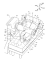
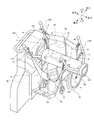
その後、図3及び図4に示すように、中央ホルダー部102が上昇することにより、被介護者50が持ち上げられ、アーム部材103,106が回動することにより、被介護者50の姿勢が移動先の車椅子W(後述の図5参照)の座位形状に合った座位姿勢(この例では骨盤51を立てた状態での座位姿勢)に変更される。そして、介護者が、座位姿勢の被介護者50を持ち上げた状態の移乗補助装置100を車椅子Wに向けて移動させる。
この際、頭部58は、第2支持部16により支持され、肩部56,56は、第1支持部14,14により各々支持される。また、脚部55,55の大腿下部54,54を支持する延設部12,12の各々が、上記部位12b,12bで交差するように互いに近づくように湾曲した形状であることから、脚部55,55が持ち上げられる際には、上記延設部12,12が交差した平面部位で大腿下部54,54が面状に支持されつつ引き上げられる。これにより、被介護者50が大腿下部54,54の痛みや不快感、皮膚の擦過傷を引き起こすのを抑制できる。また、各吊部4のシート本体2との接合部である補強布42の他端部42bが、坐骨結節53に対応する部位近傍に配置されている、言い換えれば、各吊部4が、シート本体2の坐骨結節53に対応する部位近傍に接合されていることから、座位姿勢の被介護者50の持ち上げ時や移動時に、臀部52を、体重を支える坐骨結節53の下部から支持できる。これにより、シート本体2からの被介護者50の臀部52の落ち込みを抑制できる。つまり、各吊部4は、シート本体に載置された座位姿勢の被介護者の臀部の落ち込みを抑制する手段の一例に相当する。
そして、図5に示すように、介護者が、座位姿勢の被介護者50が車椅子Wの上方位置に移動させたら、中央ホルダー部102が下降することにより、被介護者50が降ろされて車椅子Wに座らされる。この際、上述のようにシート本体2からの臀部52の落ち込みを抑制できるので、被介護者50が骨盤後傾状態での座位姿勢となるのを抑制でき、被介護者50を車椅子Wの座位形状に合った姿勢とすることが可能である。これにより、被介護者50を車椅子Wに適正に座らせる(例えば車椅子Wの深い位置に座らせる)ことができる。
なお、上記で説明したスリングシート1を用いて移乗補助装置100によって行われる被介護者50の移乗内容は、あくまで一例であって、他の内容であってもよいことは言うまでもない。例えば、上記では、被介護者50を持ち上げて被介護者50の姿勢を変更した後に、移動する場合に適用したが、被介護者50を持ち上げて移動した後に、被介護者50の姿勢を変更する場合にも適用可能である。また、上記では、臥位姿勢から座位姿勢への移乗を行う場合に適用したが、座位姿勢から臥位姿勢への移乗や、臥位姿勢から臥位姿勢への移乗(位置移動や姿勢変更等)、座位姿勢から座位姿勢への移乗(位置移動や姿勢変更等)、その他の移乗を行う場合にも適用可能なことは言うまでもない。
<本実施形態による効果の例>
以上説明したように、本実施形態のスリングシート1は、被介護者50の移乗を補助する移乗補助装置100に用いられる。このスリングシート1は、被介護者50が載置されるシート本体2と、吊部4とを有する。吊部4は、シート本体2における被介護者50の坐骨結節53に対応する部位近傍に接合されるとともに、移乗補助装置100に着脱される。
以上説明したように、本実施形態のスリングシート1は、被介護者50の移乗を補助する移乗補助装置100に用いられる。このスリングシート1は、被介護者50が載置されるシート本体2と、吊部4とを有する。吊部4は、シート本体2における被介護者50の坐骨結節53に対応する部位近傍に接合されるとともに、移乗補助装置100に着脱される。
このように構成されるスリングシート1を用いて移乗補助装置100によって被介護者50の移乗を行う際には、被介護者50を載置したスリングシート1を、吊部4を介して移乗補助装置100に取り付けることで、被介護者50が持ち上げ(吊り上げ)られる。そして、被介護者50を持ち上げた状態で、被介護者50の姿勢が所望の姿勢(例えば移動先の座位形状に合った姿勢や移乗後に実施する様々な活動に適した姿勢等)に変更される。
この際、吊部4がシート本体2における被介護者50の坐骨結節53に対応する部位近傍に接合されていることにより、例えば座位姿勢の被介護者50の持ち上げ時や移動時に、被介護者50の臀部52を、体重を支える坐骨結節53の下部から支持できる。これにより、シート本体2からの被介護者50の臀部52の落ち込みを抑制できるので、臀部52や股関節部の圧迫・締め付けを抑制できる。その結果、移乗時の被介護者50の負担を軽減でき、快適性を向上できる。
また、上述のようにシート本体2からの被介護者50の臀部52の落ち込みを抑制できるので、被介護者50が骨盤後傾状態での座位姿勢となるのを抑制でき、被介護者50を移動先の座位形状に合った姿勢(例えば骨盤51を立てた状態での座位姿勢等)とすることが可能である。これにより、被介護者50を適正に座らせる(例えば車椅子Wやトイレの深い位置に座らせる)ことができるので、移乗後の被介護者50の姿勢変更が不要となり、介護者の負担を軽減できる。
また、本実施形態では特に、シート本体2が、被介護者50の臀部52に対応する部位近傍から被介護者50の脚部55,55に対応する側に二股分岐状に延設された延設部12,12を有する。
ここで、仮に、延設部12,12の各々を、シート本体2を平面状にした際に平行又は離反するように互いに平行又は離反する方向に延びた形状とする場合、吊部6を移乗補助装置100に取り付けて被介護者50の脚部55,55を持ち上げる際に、延設部12,12を交差させ、その交差させた部位で被介護者50の大腿下部54を支持しつつ無理に引き上げられる。このため、被介護者50の大腿下部54は例えば延設部12,12の縁部等により線状に支持されることとなり、被介護者50は大腿下部54の痛みや不快感、皮膚の擦過傷を引き起こすおそれがある。
そこで本実施形態では、延設部12,12の各々を、シート本体2を平面状にした際に交差するように互いに近づく方向に湾曲した形状とする。これにより、被介護者50の脚部55,55を持ち上げる際に、延設部12,12が交差した平面部位で被介護者50の大腿下部54を面状に支持しつつ引き上げることが可能となる。その結果、被介護者50が大腿下部54の痛みや不快感、皮膚の擦過傷を引き起こすのを抑制できるので、移乗時の被介護者50の快適性を向上できる。また、延設部12.12を上記のような構成とすることにより、吊部6の長さを短くすることが可能となるので、吊り上げ式の移乗補助装置100で生じうる振り子運動による揺れを抑制できる。これにより、被介護者50の恐怖心や目眩等の症状を低減できる。また、吊部6が短いため、移乗補助装置100に対する着脱が容易であり、吊部6の移乗先の装置(例えば車椅子W等)への引っ掛かりを抑制できる。
また、本実施形態では特に、延設部12,12の各々を、シート本体2を平面状にした際に被介護者50の大腿下部54に対応する部位12bで交差するように互いに近づく方向に湾曲した形状とする。これにより、被介護者50の脚部55,55を持ち上げる際に延設部12,12が交差した平面部位で被介護者50の大腿下部54を面状に支持しつつ引き上げる実効性を向上できる。
また、本実施形態では特に、延設部12,12における他方の延設部12と交差する部位に、クッション材20,20が設置される。これにより、被介護者50の大腿下部54を保護できるので、被介護者50の負担の軽減効果を高めることができる。
また、本実施形態では特に、クッション材20を備える延設部12に、クッション材20を出し入れ可能な収容部18が設けられる。これにより、被介護者50の症状や好みに応じて使用するクッション材20の硬さ等の性能を変更できるので、利便性を向上できる。
また、本実施形態では特に、シート本体2における被介護者50の肩部56,56に対応する部位に、第1支持部14,14が設けられる。第1支持部14,14は、被介護者50の肩部56,56の形状に沿うように立体成形されている。このような第1支持部14,14によって移乗時に被介護者50の肩部56,56を支持することにより、肩部56,56や上腕部の圧迫・締め付けを軽減できるので、被介護者50の負担の軽減効果を高めることができる。
また、本実施形態では特に、シート本体2における被介護者50の頭部58に対応する部位に、第2支持部16が設けられ、第2支持部16における左右両側に、吊部8,8が配置される。吊部8,8は、第2支持部16における上下両端側に分岐して接合されるとともに、移乗補助装置100に着脱される。このような吊部8を第2支持部16が左右両側に備えることにより、吊部8,8を移乗補助装置100に取り付けて被介護者50の移乗を行う際に、第2支持部16により被介護者50の頭部58を面状に支持することが可能となる。これにより、被介護者50の頭部58を安定的に支持できるので、被介護者50の頭部58のぐらつきを軽減できる。
また、本実施形態では特に、シート本体2の表面2aに、左右方向の中心位置を表示する第1表示部22が設けられる。これにより、被介護者50をシート本体2に載置する際に、被介護者50の脊柱位置とシート本体2の左右方向中心位置とを容易に合わせることができる。また、被介護者50の脊柱位置とシート本体2の左右方向中心位置とを合わせた上で、被介護者50の移乗を行うことができるので、移乗時の被介護者50のずり落ちを防止できる。
また、本実施形態では特に、シート本体2の表面2aに、延設部12,12の基端位置を表示する第2表示部24が設けられる。これにより、被介護者50をシート本体2に載置する際に、被介護者50の臀部52を容易に適正な位置に載置できるので、上述した移乗時の被介護者50の負担の軽減効果を得ることができる。
また、本実施形態では特に、各着脱部43,63,83の長手方向の互いに異なる位置に、移乗補助装置100の係止部に着脱される複数の被係止部44,64,84が配置される。これにより、被介護者50の体格に応じて移乗補助装置100の係止部に取り付ける被係止部を変更することにより、1枚のスリングシート1を体格の異なる複数の被介護者50に用いることができるので、利便性を向上できる。また、本実施形態では、上記複数の被係止部44,64,84を互いに異なる色とする。これにより、スリングシート1の使用時の被係止部44,64,84の位置を容易に把握できるので、利便性をさらに向上できる。
<変形例等>
なお、開示の実施形態は、上記実施形態に限られるものではなく、その趣旨及び技術的思想を逸脱しない範囲内で種々の変形が可能である。
なお、開示の実施形態は、上記実施形態に限られるものではなく、その趣旨及び技術的思想を逸脱しない範囲内で種々の変形が可能である。
上記実施形態では、シート本体2に吊部が左右3箇所ずつ設けられたスリングシート1について説明したが、スリングシートは、この構成に限定されるものではない。例えば、スリングシートとして、シート本体に吊部が左右2箇所ずつ又は左右1箇所ずつ又は左右4箇所以上ずつ設けられたスリングシートを使用してもよい。また、スリングシートとしては、シート本体に吊部が左右対称に設けられたスリングシートに限定されるものではない。また、スリングシートの吊部として、シート本体に左右両側に亘って設けられた、つまりシート本体の左右両側に接合部と着脱部を備えた、環状の吊部を使用してもよい。
また、上記実施形態では、被介護者50の移乗を補助する移乗補助装置100に用いられるスリングシート1について説明したが、スリングシートの用途は、移乗補助装置に限定されるものではない。例えば、スリングシートは、利用者を載置して吊り上げる動作が行われる用途であれば、いずれの用途にも使用可能である。また、スリング動作(利用者を吊り上げる動作)を行わない用途に使用されるシートに対し、上記実施形態等で説明した手法を応用することも可能である。
なお、以上の説明における「鉛直」「垂直」「直線」「水平」「一致」とは、厳密な意味ではない。すなわち、「鉛直」「垂直」「直線」「水平」「一致」とは、設計上、製造上の公差、誤差が許容され、「実質的に鉛直」「実質的に垂直」「実質的に直線」「実質的に水平」「実質的に一致」という意味である。
また、以上の説明において、外観上の寸法や大きさが「同一」「等しい」「異なる」等の記載がある場合は、当該記載は厳密な意味ではない。すなわち、それら「同一」「等しい」「異なる」等とは、設計上、製造上の公差、誤差が許容され、「実質的に同一」「実質的に等しい」「実質的に異なる」等という意味である。
また、以上既に述べた以外にも、上記実施形態や各変形例による手法を適宜組み合わせて利用しても良い。
その他、一々例示はしないが、上記実施形態や各変形例は、その趣旨を逸脱しない範囲内において、種々の変更が加えられて実施されるものである。
1 スリングシート
2 シート本体
2a 表面(被介護者が載置される面の一例)
4 吊部(第1吊部、第4吊部の一例)
6 吊部(第2吊部の一例)
8 吊部(第3吊部の一例)
12 延設部
12a 先端部
12b 部位(被介護者の大腿下部に対応する部位の一例)
14 第1支持部
16 第2支持部
18 収容部
20 クッション材
22 第1表示部
24 第2表示部
43 着脱部(第1着脱部、第4着脱部の一例)
42b 他端部(第1接合部、第4接合部の一例)
44 被係止部
50 被介護者
52 臀部
53 坐骨結節
54 大腿下部
55 脚部
56 肩部
58 頭部
60a 端部(第2接合部の一例)
63 着脱部(第2着脱部の一例)
64 被係止部
80a 端部(第3接合部の一例)
83 着脱部(第3着脱部の一例)
84 被係止部
100 移乗補助装置
104 係止部
105 係止部
107 係止部
108 係止部
2 シート本体
2a 表面(被介護者が載置される面の一例)
4 吊部(第1吊部、第4吊部の一例)
6 吊部(第2吊部の一例)
8 吊部(第3吊部の一例)
12 延設部
12a 先端部
12b 部位(被介護者の大腿下部に対応する部位の一例)
14 第1支持部
16 第2支持部
18 収容部
20 クッション材
22 第1表示部
24 第2表示部
43 着脱部(第1着脱部、第4着脱部の一例)
42b 他端部(第1接合部、第4接合部の一例)
44 被係止部
50 被介護者
52 臀部
53 坐骨結節
54 大腿下部
55 脚部
56 肩部
58 頭部
60a 端部(第2接合部の一例)
63 着脱部(第2着脱部の一例)
64 被係止部
80a 端部(第3接合部の一例)
83 着脱部(第3着脱部の一例)
84 被係止部
100 移乗補助装置
104 係止部
105 係止部
107 係止部
108 係止部
Claims (11)
- 被介護者(50)の移乗を補助する移乗補助装置(100)に用いられるスリングシート(1)であって、
前記被介護者(50)が載置されるシート本体(10)と、
前記シート本体(10)における前記被介護者(50)の坐骨結節(53)に対応する部位近傍に接合された第1接合部(42b)、及び、前記移乗補助装置(100)に着脱される第1着脱部(43)、を備えた第1吊部(4)と、
を有することを特徴とするスリングシート(1)。 - 前記シート本体(10)は、
前記被介護者(50)の臀部(52)に対応する部位近傍から前記被介護者(50)の脚部(55)に対応する側に二股分岐状に延設された2つの延設部(12)を有し、
前記スリングシート(1)は、
前記延設部(12)の先端部(12a)に接合された第2接合部(60a)、及び、前記移乗補助装置(100)に着脱される第2着脱部(63)、を備えた一対の第2吊部(6)をさらに有し、
前記2つの延設部(12)の各々は、
前記シート本体(10)を平面状にした際に交差するように互いに近づく方向に湾曲した形状である
ことを特徴とする請求項1に記載のスリングシート(1)。 - 前記2つの延設部(12)の各々は、
前記被介護者(50)の大腿下部(54)に対応する部位(12b)で交差するように互いに近づく方向に湾曲した形状である
ことを特徴とする請求項2に記載のスリングシート(1)。 - 前記2つの延設部(12)の少なくとも一方は、
他方の前記延設部(12)と交差する部位に設置されたクッション材(20)を備える
ことを特徴とする請求項2又は3に記載のスリングシート(1)。 - 前記クッション材(20)を備える前記延設部(12)は、
前記クッション材(20)が出し入れされる収容部(18)を備える
ことを特徴とする請求項4に記載のスリングシート(1)。 - 前記シート本体(10)は、
前記被介護者(50)の肩部(56)に対応する部位に、当該肩部(56)の形状に沿うように立体成形された、前記肩部(56)が支持される第1支持部(14)を有する
ことを特徴とする請求項1乃至5のいずれか1項に記載のスリングシート(1)。 - 前記シート本体(10)は、
前記被介護者(50)の頭部(58)に対応する部位に、当該頭部(58)が支持される第2支持部(16)を有し、
前記スリングシート(1)は、
前記第2支持部(16)における前記被介護者(50)の幅方向に対応する方向の両側に配置され、前記第2支持部(16)における前記被介護者(50)の身長方向に対応する方向の両端側に分岐して接合された第3接合部(80a)及び前記移乗補助装置(100)に着脱される第3着脱部(83)を備えた、一対の第3吊部(8)をさらに有する
ことを特徴とする請求項1乃至6のいずれか1項に記載のスリングシート(1)。 - 前記シート本体(10)は、
少なくとも前記被介護者(50)が載置される側の面(2a)に、前記被介護者(50)の幅方向に対応する方向の中心位置を表示するように構成された第1表示部(22)を有する
ことを特徴とする請求項1乃至7のいずれか1項に記載のスリングシート(1)。 - 前記シート本体(10)は、
少なくとも前記被介護者(50)が載置される側の面(2a)に、延設部(12)の基端位置を表示するように構成された第2表示部(24)を有する
ことを特徴とする請求項2乃至8のいずれか1項に記載のスリングシート(1)。 - 前記第1着脱部(43)、第2着脱部(63)、及び第3着脱部(83)の少なくとも1つは、
当該着脱部(43,63,83)の長手方向の互いに異なる位置に配置され、前記移乗補助装置(100)の係止部(104,105,107,108)に着脱される、互いに異なる色の複数の被係止部(44,64,84)を備える
ことを特徴とする請求項1乃至9のいずれか1項に記載のスリングシート(1)。 - 被介護者(50)の移乗を補助する移乗補助装置(100)に用いられるスリングシート(1)であって、
前記被介護者(50)が載置されるシート本体(10)と、
前記シート本体(10)における前記被介護者(50)の幅方向に対応する方向の中心位置から当該方向に所定の距離離間した位置に接合された第4接合部(42b)、及び、前記移乗補助装置(100)に着脱される第4着脱部(43)、を備えた第4吊部(4)と、
を有することを特徴とするスリングシート(1)。
Priority Applications (1)
| Application Number | Priority Date | Filing Date | Title |
|---|---|---|---|
| CN201590000386.4U CN206120635U (zh) | 2014-04-10 | 2015-04-01 | 悬带座椅 |
Applications Claiming Priority (2)
| Application Number | Priority Date | Filing Date | Title |
|---|---|---|---|
| JP2014-081394 | 2014-04-10 | ||
| JP2014081394A JP2015202121A (ja) | 2014-04-10 | 2014-04-10 | スリングシート |
Publications (1)
| Publication Number | Publication Date |
|---|---|
| WO2015156189A1 true WO2015156189A1 (ja) | 2015-10-15 |
Family
ID=54287766
Family Applications (1)
| Application Number | Title | Priority Date | Filing Date |
|---|---|---|---|
| PCT/JP2015/060358 Ceased WO2015156189A1 (ja) | 2014-04-10 | 2015-04-01 | スリングシート |
Country Status (3)
| Country | Link |
|---|---|
| JP (1) | JP2015202121A (ja) |
| CN (1) | CN206120635U (ja) |
| WO (1) | WO2015156189A1 (ja) |
Families Citing this family (1)
| Publication number | Priority date | Publication date | Assignee | Title |
|---|---|---|---|---|
| WO2022044244A1 (ja) | 2020-08-28 | 2022-03-03 | 株式会社竹虎 | 介護用スリングシート |
Citations (6)
| Publication number | Priority date | Publication date | Assignee | Title |
|---|---|---|---|---|
| JPH05136U (ja) * | 1991-06-17 | 1993-01-08 | 株式会社コイケ | 介護用移動吊具 |
| JPH07236663A (ja) * | 1994-02-25 | 1995-09-12 | Kiyoshi Iwanami | 介護用スリング |
| JPH1099385A (ja) * | 1996-09-27 | 1998-04-21 | Yabe Sangyo Kk | ワンタッチ・ワンピース脱着型吊りシート |
| JPH11253511A (ja) * | 1998-03-17 | 1999-09-21 | Hitachi Chem Co Ltd | 介護用シート、及び該介護用シートを係止した自立歩行支援機 |
| US6289534B1 (en) * | 1998-07-31 | 2001-09-18 | Hill-Rom Services, Inc. | Patient lift |
| JP2008036100A (ja) * | 2006-08-04 | 2008-02-21 | Moritoo:Kk | スリングシート |
Family Cites Families (1)
| Publication number | Priority date | Publication date | Assignee | Title |
|---|---|---|---|---|
| JP5307613B2 (ja) * | 2009-04-22 | 2013-10-02 | 株式会社リフトケア | スリングシート及び該スリングシートを備えた介護用吊り装置 |
-
2014
- 2014-04-10 JP JP2014081394A patent/JP2015202121A/ja active Pending
-
2015
- 2015-04-01 WO PCT/JP2015/060358 patent/WO2015156189A1/ja not_active Ceased
- 2015-04-01 CN CN201590000386.4U patent/CN206120635U/zh not_active Expired - Fee Related
Patent Citations (6)
| Publication number | Priority date | Publication date | Assignee | Title |
|---|---|---|---|---|
| JPH05136U (ja) * | 1991-06-17 | 1993-01-08 | 株式会社コイケ | 介護用移動吊具 |
| JPH07236663A (ja) * | 1994-02-25 | 1995-09-12 | Kiyoshi Iwanami | 介護用スリング |
| JPH1099385A (ja) * | 1996-09-27 | 1998-04-21 | Yabe Sangyo Kk | ワンタッチ・ワンピース脱着型吊りシート |
| JPH11253511A (ja) * | 1998-03-17 | 1999-09-21 | Hitachi Chem Co Ltd | 介護用シート、及び該介護用シートを係止した自立歩行支援機 |
| US6289534B1 (en) * | 1998-07-31 | 2001-09-18 | Hill-Rom Services, Inc. | Patient lift |
| JP2008036100A (ja) * | 2006-08-04 | 2008-02-21 | Moritoo:Kk | スリングシート |
Also Published As
| Publication number | Publication date |
|---|---|
| JP2015202121A (ja) | 2015-11-16 |
| CN206120635U (zh) | 2017-04-26 |
Similar Documents
| Publication | Publication Date | Title |
|---|---|---|
| CN107847379B (zh) | 转移辅助装置 | |
| JP2016140435A (ja) | 移乗支援装置 | |
| JP3144879U (ja) | 背負い具 | |
| KR20240072493A (ko) | 환자 이송용 상체리프트 휠체어 장치 | |
| CN204995675U (zh) | 悬带座椅、换乘辅助装置 | |
| TW514524B (en) | Seat lifting device for wheelchair | |
| JP6587444B2 (ja) | 移乗支援装置 | |
| WO2015156189A1 (ja) | スリングシート | |
| JP6594621B2 (ja) | 介護用枕 | |
| JP2018157923A (ja) | 身体支持装置 | |
| TWI386197B (zh) | Multi - mode shift machine | |
| CN205054628U (zh) | 悬带座椅、换乘辅助装置 | |
| JP3174152U (ja) | 上体支持用補助具 | |
| JP5588271B2 (ja) | 介助用移乗器 | |
| JP3215104U (ja) | 介護リフト用吊り具 | |
| JP4221482B2 (ja) | 携帯用簡易担架 | |
| JP2016119927A (ja) | 介護用枕 | |
| JP2017056105A (ja) | ベッド装置 | |
| TW201507715A (zh) | 移動用機器 | |
| US11439556B2 (en) | Examination table | |
| JP2018157924A (ja) | 身体支持装置 | |
| JP3124647U (ja) | 介助用具 | |
| JP2006181160A (ja) | 介護用移動マット | |
| JP2026043029A (ja) | 介助装置 | |
| CN121443251A (zh) | 支持行动不便者的可重构系统 |
Legal Events
| Date | Code | Title | Description |
|---|---|---|---|
| 121 | Ep: the epo has been informed by wipo that ep was designated in this application |
Ref document number: 15777132 Country of ref document: EP Kind code of ref document: A1 |
|
| NENP | Non-entry into the national phase |
Ref country code: DE |
|
| 122 | Ep: pct application non-entry in european phase |
Ref document number: 15777132 Country of ref document: EP Kind code of ref document: A1 |