WO2015152259A1 - スポイト容器 - Google Patents
スポイト容器 Download PDFInfo
- Publication number
- WO2015152259A1 WO2015152259A1 PCT/JP2015/060169 JP2015060169W WO2015152259A1 WO 2015152259 A1 WO2015152259 A1 WO 2015152259A1 JP 2015060169 W JP2015060169 W JP 2015060169W WO 2015152259 A1 WO2015152259 A1 WO 2015152259A1
- Authority
- WO
- WIPO (PCT)
- Prior art keywords
- peripheral wall
- lid
- dropper
- outer peripheral
- wall
- Prior art date
- Legal status (The legal status is an assumption and is not a legal conclusion. Google has not performed a legal analysis and makes no representation as to the accuracy of the status listed.)
- Ceased
Links
Images




Classifications
-
- B—PERFORMING OPERATIONS; TRANSPORTING
- B01—PHYSICAL OR CHEMICAL PROCESSES OR APPARATUS IN GENERAL
- B01L—CHEMICAL OR PHYSICAL LABORATORY APPARATUS FOR GENERAL USE
- B01L3/00—Containers or dishes for laboratory use, e.g. laboratory glassware; Droppers
- B01L3/02—Burettes; Pipettes
- B01L3/0241—Drop counters; Drop formers
- B01L3/0272—Dropper bottles
-
- B—PERFORMING OPERATIONS; TRANSPORTING
- B01—PHYSICAL OR CHEMICAL PROCESSES OR APPARATUS IN GENERAL
- B01L—CHEMICAL OR PHYSICAL LABORATORY APPARATUS FOR GENERAL USE
- B01L3/00—Containers or dishes for laboratory use, e.g. laboratory glassware; Droppers
- B01L3/02—Burettes; Pipettes
- B01L3/0282—Burettes; Pipettes mounted within a receptacle
-
- B—PERFORMING OPERATIONS; TRANSPORTING
- B01—PHYSICAL OR CHEMICAL PROCESSES OR APPARATUS IN GENERAL
- B01L—CHEMICAL OR PHYSICAL LABORATORY APPARATUS FOR GENERAL USE
- B01L2300/00—Additional constructional details
- B01L2300/04—Closures and closing means
- B01L2300/041—Connecting closures to device or container
- B01L2300/044—Connecting closures to device or container pierceable, e.g. films, membranes
-
- B—PERFORMING OPERATIONS; TRANSPORTING
- B01—PHYSICAL OR CHEMICAL PROCESSES OR APPARATUS IN GENERAL
- B01L—CHEMICAL OR PHYSICAL LABORATORY APPARATUS FOR GENERAL USE
- B01L2300/00—Additional constructional details
- B01L2300/04—Closures and closing means
- B01L2300/046—Function or devices integrated in the closure
- B01L2300/047—Additional chamber, reservoir
-
- B—PERFORMING OPERATIONS; TRANSPORTING
- B01—PHYSICAL OR CHEMICAL PROCESSES OR APPARATUS IN GENERAL
- B01L—CHEMICAL OR PHYSICAL LABORATORY APPARATUS FOR GENERAL USE
- B01L2300/00—Additional constructional details
- B01L2300/08—Geometry, shape and general structure
- B01L2300/0832—Geometry, shape and general structure cylindrical, tube shaped
- B01L2300/0835—Ampoules
-
- B—PERFORMING OPERATIONS; TRANSPORTING
- B01—PHYSICAL OR CHEMICAL PROCESSES OR APPARATUS IN GENERAL
- B01L—CHEMICAL OR PHYSICAL LABORATORY APPARATUS FOR GENERAL USE
- B01L2300/00—Additional constructional details
- B01L2300/12—Specific details about materials
- B01L2300/123—Flexible; Elastomeric
-
- B—PERFORMING OPERATIONS; TRANSPORTING
- B01—PHYSICAL OR CHEMICAL PROCESSES OR APPARATUS IN GENERAL
- B01L—CHEMICAL OR PHYSICAL LABORATORY APPARATUS FOR GENERAL USE
- B01L2400/00—Moving or stopping fluids
- B01L2400/04—Moving fluids with specific forces or mechanical means
- B01L2400/0475—Moving fluids with specific forces or mechanical means specific mechanical means and fluid pressure
- B01L2400/0478—Moving fluids with specific forces or mechanical means specific mechanical means and fluid pressure pistons
Definitions
- the present invention relates to a syringe container.
- This application claims priority based on Japanese Patent Application No. 2014-071967 for which it applied to Japan on March 31, 2014, and uses the content here.
- a dropper tube which is composed of a container body having a mouth / neck portion and a lid attached to the mouth / neck portion, is attached to a through-hole opened in the base of the lid, and the mouth / neck portion is interposed therebetween.
- a dropper container having a push button for hanging the elastic dome into a fitting groove formed in a lid portion around the dropper tube and for pushing down the elastic dome is also known. (See FIG. 2 of Patent Document 1).
- An object of the present invention is to provide a dropper container with good setability, in which an elastically deformable member can be easily set on a lid.
- a first aspect of the present invention is a container that stands up the mouth and neck, a lid base that is placed on the mouth and neck, and a movable lid that is urged upward relative to the lid base so as to be movable up and down
- a dropper comprising: an elastically deformable member that covers the upper surface of the movable lid portion; and a lid that includes a dropper tube that is linked to the lid base portion below the engagement recess formed on the upper portion of the tube wall and hangs down to the lower portion of the container.
- the lid base has a base part projecting outward from the link with the dropper tube, and the base part is locked to the upper side of the mouth and neck part.
- An engaging claw capable of moving up and down in the engaging recess is attached to the inner surface of the locking cylinder portion, and in liquid-tight contact with the inner surface of the inner peripheral wall between the lid base portion and the flange-like top wall portion of the movable lid portion.
- a piston member is provided, and the lower end portion of the elastic deformation member is fitted into the upper portion of the gap between the outer peripheral wall and the inner peripheral wall.
- the lid of the dropper container is configured such that the movable lid is movable up and down relative to the lid base, and the lower end of the elastic deformation member is placed in the upper part of the gap between the outer peripheral wall and the inner peripheral wall of the movable lid.
- the structure which inserts a part is provided. For this reason, since the air in the gap can escape downward, for example, when the lower end portion of the elastic deformation member is set in the gap, the elastic deformation member can be avoided from floating.
- the elastic deformation member may be the illustrated elastic dome, or may be an elastic squeezing tool using bellows.
- the gap communicates as the air vent passage below the lid base portion through a gap between the substrate portion and the outer peripheral wall.
- the gap is communicated as the air vent passage below the lid base.
- the lower half portion of the outer peripheral wall is screwed to the outer surface of the mouth neck portion, and each of the inner peripheral wall and the circumferential portion of the outer peripheral wall is connected to the connecting piece.
- the locking wall portion is raised from the outer periphery of the substrate portion to the gap between the inner peripheral wall and the outer peripheral wall, and the locking wall portion is locked to the connecting piece as a detent member of the lid base portion with respect to the movable lid portion.
- a part of the inner peripheral wall and the outer peripheral wall in the circumferential direction are connected by a connecting piece, and the locking wall portion is erected from the outer periphery of the substrate portion to the gap between the inner peripheral wall and the outer peripheral wall.
- the locking wall portion is locked to the connecting piece as a detent member for the lid base portion with respect to the movable lid portion. Since the anti-rotation member is accommodated in the gap, the space can be used effectively.
- the lid fits with a lower portion of the outer peripheral wall of the movable lid portion and presses the lower end portion of the elastic deformation member from above.
- the cover member is provided on the upper side, and the upper surface of the cover is formed by the upper outer surface of the cover member and the upper surface of the elastic deformation member.
- the upper surface of the lid is formed by the upper outer surface of the cover member and the upper surface of the elastic deformation member.
- the height of the container can be lowered compared to the prior art in which a push button for pressing the elastic deformation member is provided on the upper side of the elastic deformation member.
- the piston member in any one of the first to third aspects, includes an outer cylinder part formed with a piston part in liquid-tight contact with the inner surface of the inner peripheral wall, and a locking cylinder part.
- an inner cylinder part inserted into the inner cylinder part, and an inner surface of the inner cylinder part is provided with a temporary fixing protrusion that is locked from above with respect to a locking protrusion part provided on the outer surface of the locking cylinder part Has been.
- the inner cylinder part is provided with a temporary fixing protrusion that is locked from above with respect to the locking protrusion of the locking cylinder part.
- the locking cylinder portion of the movable lid portion is inserted into the inner cylinder portion of the piston member, the temporary fixing protrusion of the inner cylinder portion is moved over the locking protrusion of the locking cylinder portion, and the piston member alone is It is possible to assemble the lid base and dropper tube to the movable wall in a state of being temporarily fixed to the movable wall, as compared with the case where the assembly in which the piston member and the lid base are assembled is attached to the movable lid.
- the syringe container can be assembled easily.
- the lower end portion of the elastic deformation member is inserted into the upper end portions of the outer peripheral wall and the inner peripheral wall that are arranged with a gap between each other, compared to the case where the elastic deformation member is inserted into the fitting groove.
- the repulsion of air is reduced, the fitting work can be performed smoothly, and the setability is good.
- the gap communicates with the lower part of the lid base portion through the gap between the substrate portion and the outer peripheral wall as an air vent passage, the setability is good.
- the gap between the outer peripheral wall and the inner peripheral wall is also used as an installation place for the locking wall portion which is a rotation preventing member for the lid base portion with respect to the movable lid portion, and as an air vent passage.
- the dropper container does not become tall.
- the inner cylinder part is provided with a temporary fixing protrusion that is locked from above with respect to the locking protrusion of the locking cylinder part, the assembly in which the piston member and the lid base are assembled is provided. The dropper container can be easily assembled as compared with the case where it is attached to the movable lid portion.
- FIG. 5 is a partially enlarged view of FIG. 4.
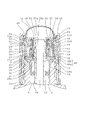
- FIG. 1 to 3 show a dropper container according to the first embodiment of the present invention.
- FIG. 1 is a longitudinal sectional view of a dropper container according to the first embodiment of the present invention.
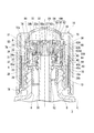
- FIG. 2 is an enlarged view of a main part of the container of FIG.
- FIG. 3 is an explanatory view showing a state where the movable lid portion of the container of FIG. 1 is raised.
- This dropper container is composed of a container 2 and a lid 16.
- Each of these members can be formed of, for example, a synthetic resin or a metal.
- the container 2 includes a container body 4 and a squeeze member 8 as shown in FIG.
- the container body 4 has a mouth-and-neck portion 6 with an upper end opened up from the trunk portion through the shoulder portion.
- a screw thread is formed on the outer surface of the mouth-and-neck portion 6.
- the squeeze member 8 includes a main cylinder part 10 having a hook part 10a that can be locked to the upper surface of the mouth and neck part 6, and a squeeze part 12 protruding from the inner surface of the main cylinder part.
- the squealing portion 12 is in contact with the outer surface of a later-described dropper tube 30.
- the lid 16 includes a lid base portion 18, a dropper tube 30, a movable lid portion 38, a piston member 60, an elastic dome 72 that is an elastic deformation member, and a cover member 76.
- the lid base 18 is provided with an inward annular plate portion 21 at the upper end of the vertical base tube portion 20, and the base plate portion 22 protrudes outward from the lower end of the base tube portion 20. Is formed.
- a packing 28 is attached to the lower surface of the substrate portion 22, and is placed on the flange portion 10 a of the squeeze member 8.
- a cylindrical locking wall portion 24 stands from the outer end of the substrate portion 22. The locking wall portion 24 is intermittently provided with slits 26 in the longitudinal direction in the circumferential direction.
- the structure of the lid base 18 can be changed as appropriate.
- an engagement recess 32 a is formed at the upper portion of the tube wall, and the lid base 18 is linked to the lower side of the engagement recess.
- the dropper tube 30 is perpendicular to the bottom of the container body 4 from this linkage location. Is arranged.
- the engagement concave portion 32a is provided wide vertically so that an engagement claw 58a described later can be moved up and down.
- the tube wall portion above the packing 28 is formed so as to increase in diameter sequentially from the upper side to the lower diameter cylindrical portion 32, the intermediate diameter cylindrical portion 34, and the large diameter cylindrical portion 36.
- An engaging recess 32a, a fitting groove 34a in the middle diameter cylindrical portion 34, and a ring holding groove 36a in the large diameter cylindrical portion 36 are respectively provided.
- the annular plate portion 21 is fitted in the fitting groove 34a, and the O-ring 37 is fitted in the ring holding groove 36a.
- the shape of these members can be changed as appropriate.
- the movable lid portion 38 includes an outer peripheral wall 40, an inner peripheral wall 50, a flange-like top wall portion 52, and a locking cylinder portion 58.
- the lower half 40 a of the outer peripheral wall 40 is screwed to the outer surface of the mouth and neck 6, and the upper half 40 b of the outer peripheral wall 40 stands up above the substrate portion 22.
- the upper half 40b shown in the figure has a smaller outer diameter than the lower half.
- An upward outer fitting step S ⁇ b> 1 is provided around the upper end of the inner surface of the outer peripheral wall 40.
- a gap A is formed between the outer peripheral wall 40 and the substrate portion 22 to communicate a gap G, which will be described later, below the lid base portion 18.
- the inner peripheral wall 50 is connected to the upper half portion 40b of the outer peripheral wall 40 through an appropriate number of connecting pieces 48 so as to be positioned with a certain gap G.
- An inner fitting step S2 is provided around the upper end of the outer surface of the inner peripheral wall 50 so as to face the outer fitting step S1.
- the connecting piece 48 is provided intermittently in the circumferential direction so as to connect an appropriate position (lower end in the illustrated example) of the inner peripheral wall 50 below the inner fitting step S2 and the upper half of the outer peripheral wall 40. Also good.
- a slit 26 of the locking wall portion 24 is inserted into the connecting piece 48, and functions as a detent member for the lid base portion with respect to the movable lid.
- the flange-like top wall portion 52 extends inward from the upper portion of the inner peripheral wall 50.
- An appropriate number of air holes 54 are opened in the inner peripheral portion of the flange-like top wall portion 52.
- the outer peripheral portion of the flange-like top wall portion 52 is recessed in an annular shape, and the inside of the recessed wall portion 56 is formed so that a coil spring 70 described later can come into contact therewith.
- the locking cylinder portion 58 hangs down from the inner edge of the flange-like top wall portion 52, and an annular engagement claw 58 a attached to the inner surface of the lower end portion of the locking cylinder portion 58 moves up and down into the engagement recess 32 a of the dropper tube 30. It is inserted freely.
- the lower end portions of the inner cylinder portion 62A and the outer cylinder portion 62B are connected by the bottom wall portion 64, the leg cylinder portion 68 hangs down from the bottom wall portion 64, and the upper end portion of the outer cylinder portion 62B.
- a piston portion 66 is formed on the outer surface.
- the inner cylinder 62A is slidably fitted to the outer surface of the locking cylinder 58, and the piston 66 is slidably fitted to the inner surface of the inner peripheral wall 50.
- the leg cylinder part 68 is fitted on the outer surface of the base cylinder part 20.
- a coil spring 70 is interposed between the upper surface of the bottom wall portion 64 and the flange-like top wall portion 52.
- the elastic dome 72 is fitted in the upper part of the gap G with the lower end 72a as a thick fitting ring.
- the lower outer edge and inner edge of the lower end 72a of the elastic dome 72 are locked to the outer fitting step S1 and the inner fitting step S2.
- the lower end portion 72a of the elastic dome 72 is formed to have a larger outer diameter than the dome portion continuous with the lower end portion, and the upper surface of the lower end portion 72a is a pressed surface 74.
- it may replace with an elastic dome and may use a conventionally well-known pressing tool.
- the cover member 76 is fitted so that the lower end portion (engagement end portion 78) of the cylindrical wall covering the outer surface of the outer peripheral wall 40 can be prevented from rotating to the lower end portion of the outer peripheral wall 40. Further, the upper end portion of the cylindrical wall is folded downward and inwardly to be formed in the pressing portion 80, and the pressing portion 80 is provided so that the pressed surface 74 can be pressed.
- the lid base 18 is attached to the dropper tube 30, the piston member 60 and the movable lid 38 are sequentially assembled, and then the lower end 72 a of the elastic dome 72 is placed in the upper part of the gap G of the movable lid 38. Is inserted. Since the gap G communicates below the lid base 18, it is possible to avoid inconveniences such as causing the lower end of the elastic dome 72 to rise without the air in the gap being released.
- the cover member 76 is further fitted to the outside of the outer peripheral wall 40, and the pressed surface 74 of the lower end portion 72 a is pressed by the pressing portion 80 of the cover member 76.
- the outer peripheral wall 40 is rotated together with the cover member 76 (see FIG. 3), and is screwed off from the mouth and neck portion 6. Then, the movable lid portion 38 is raised by the elastic force of the coil spring 70, the air in the elastic dome 72 is sucked into the space between the movable lid portion 38 and the lid base portion 18, and the liquid in the container body 4 is dropped into the dropper tube 30. Sucked inside. Thereafter, the lid 16 is pulled up from the container 2 side, and the elastic dome 72 is squeezed to allow the liquid to be dropped from the dropper tube 30.
- FIG. 4 is an enlarged view of a main part of a dropper container according to the second embodiment of the present invention.
- FIG. 5 is a view of the packing of FIG. 4 as viewed from below.
- FIG. 6 is a partially enlarged view of FIG.
- the piston 66 is slid upward on the inner surface 50 ⁇ / b> A of the inner peripheral wall 50 with the coil spring 70 interposed between the bottom wall 64 and the flange-like top wall 52. Meanwhile, the locking cylinder part 58 of the movable lid part 38 is inserted into the inner cylinder part 62 ⁇ / b> A of the piston member 60.
- the locking projection 58b of the locking cylinder 58 is climbed upward by a temporary locking projection 62C provided on the inner surface 62AA of the inner cylinder 62A, whereby the piston member 60 alone is temporarily fixed to the movable lid 38. . Thereafter, the assembly in which the lid base 18 and the dropper tube 30 are assembled is assembled to the movable lid 38. At this time, the piston member 60 is compressed in the vertical direction while the upper part of the base cylinder part 20 of the lid base 18 is fitted in the lower part of the leg cylinder part 68 of the piston member 60. While being deformed, the movable lid 38 is raised by a predetermined amount.
- the engagement claw 58 a of the locking cylinder portion 58 is caused to enter the engagement recess 32 a of the dropper tube 30.
- the piston member 60 is pushed down with respect to the movable lid portion 38 by the biasing force of the coil spring 70, and the base tube portion 20 is fitted into the leg tube portion 68 over the entire length in the vertical direction.
- a member composed of the inner peripheral wall 50, the flange-like top wall portion 52, the depressed wall portion 56, and the locking cylinder portion 58 is referred to as a cylinder portion 100.
- a valve body 27 is provided in the locking cylinder portion 58 corresponding to the inner peripheral wall of the cylinder portion 100 to close the upper end opening of the dropper tube 30 so as to be freely opened and closed.
- the valve body 27 is disposed on the central axis of the container body 4, and is connected to the upper end portion of the locking cylinder portion 58 via the bridge 29.
- a plurality of bridge portions 29 are arranged at intervals in the circumferential direction.
- the inside of the dropper tube 30 communicates with the space inside the elastic dome 72 when the movable lid portion 38 rises with respect to the dropper tube 30 and the upper end opening of the dropper tube 30 is opened by the valve body 27. . That is, the inside of the dropper tube 30 can communicate with the space in the elastic dome 72.
- the outer peripheral wall 40 is rotated together with the cover member 76 (see FIG. 3), and the movable lid portion 38 is screwed off from the mouth / neck portion 6. Then, the movable lid portion 38 is lifted by the elastic force of the coil spring 70, the air in the elastic dome 72 is sucked into the space between the movable lid portion 38 and the lid base portion 18, and the valve body 27 is opened at the upper end of the dropper tube 30. In order to release the liquid, the liquid in the container body 4 is sucked into the dropper tube 30. Thereafter, the lid 16 is pulled up from the container 2 side, and the elastic dome 72 is squeezed to allow the liquid to be dropped from the dropper tube 30.
- the movable lid portion 38 is detached from the container body 4 and the contents are poured out from the dropper tube 30 as described above. Thereafter, when the movable lid portion 38 is attached to the container body 4, when the movable lid portion 38 is lowered with respect to the lid base portion 18, the piston portion 66 of the lid base portion 18 moves inside the cylinder portion 100 of the movable lid portion 38. By sliding relatively upward, the internal volume of the cylinder part 100 is reduced. At this time, a crushing protrusion 28b protruding downward is formed on the lower surface of the packing 28 disposed between the lid base 18 and the upper end opening edge of the mouth neck 6 of the container body 4. (See FIGS. 5 and 6).
- a communication gap 28c is formed between the lid base 18 and the upper end opening edge of the container body 4 to communicate the inside and outside of the container body 4 (see FIG. 6). Therefore, the decrease in the internal volume of the cylinder portion 100 described above is exhausted to the container body 4 through the air hole 54, the space in the elastic dome 72, the dropper tube 30, the container body 4, and the communication gap 28c. 4 is suppressed. Thereby, irrespective of the remaining amount of the contents in the container body 4, the amount of the contents sucked into the dropper tube can be made constant with high accuracy.
- the packing 28 is pressed between the lid base 18 and the upper end opening edge of the container body 4, and in particular, the crushing protrusion 28 b is brought into contact with the upper end opening edge of the container body 4. It is crushed (see FIG. 4).
- the overhanging recess 28d is formed immediately above the crushing protrusion 28b, the overhanging recess 28d allows deformation of the crushing protrusion 28b to the upper surface side (see FIGS. 5 and 6). ). Therefore, the crushing of the crushing protrusion 28b to the upper side occurs smoothly without great resistance. Thereby, the sealing performance between the lid base 18 by the packing 28 and the upper end opening edge of the container body 4 is ensured satisfactorily.
- the valve element 27 closes the upper opening of the dropper tube 30 in the initial state. Therefore, for example, even if the lid 16 is unintentionally operated in the initial state, it is possible to prevent the contents in the container body 4 from flowing into the dropper tube 30 by mistake. Therefore, it is possible to ensure a constant amount of content dispensed from the dropper tube 30 with high accuracy. Further, for example, even if the contents of the container body 4 flow into the dropper pipe 30 due to the dropper of the dropper container in the initial state, the contents can be blocked by the valve body 27. Therefore, the contents can be restricted from flowing into the space in the elastic dome 72.
- the lower end portion of the elastic deformation member is inserted into the upper end portions of the outer peripheral wall and the inner peripheral wall that are arranged with a gap between each other, compared to the case where the elastic deformation member is inserted into the fitting groove.
- the repulsion of air becomes small, the fitting work can be performed smoothly, and a dropper container with good setability can be provided.
Landscapes
- Health & Medical Sciences (AREA)
- Clinical Laboratory Science (AREA)
- Chemical & Material Sciences (AREA)
- Chemical Kinetics & Catalysis (AREA)
- Closures For Containers (AREA)
Abstract
Description
本願は、2014年3月31日に日本国に出願された特願2014-071967号に基づき優先権を主張し、その内容をここに援用する。
本発明の第5の態様は、第1からの第3の何れかの態様において、ピストン部材は、内周壁の内面に液密に接するピストン部が形成された外筒部と、係止筒部が内側に挿入された内筒部と、を備え、内筒部の内面には、係止筒部の外面に付設された係止突部に対して上方から係止される仮止め突起が付設されている。
本発明の第5の態様では、内筒部の内面に、係止筒部の係止突部に対して上方から係止される仮止め突起が付設されているので、このスポイト容器を組み立てる過程で、ピストン部材における内筒部内に、可動蓋部の係止筒部を挿入し、内筒部の仮止め突起を、係止筒部の係止突起を上方に乗り越えさせて、ピストン部材単体を可動壁部に仮固定した状態で、蓋基部およびスポイト管を可動壁部に組み付けることが可能になり、ピストン部材と蓋基部とが組み立てられた組立体を可動蓋部に装着する場合に比べて、スポイト容器を容易に組み立てることができる。
また間隙がエア抜き通路として基板部と外周壁との空隙を介して蓋基部の下方へ連通しているため、セット性がよい。
また外周壁及び内周壁の間隙を、可動蓋部に対する蓋基部の回り止め部材である係止壁部の設置場所、及び、エア抜き通路として兼用している。そのため、コンパクトな構成とすることができる。
またカバー部材上部の外面と弾性変形部材の上面とで蓋の上面を形成しており、弾性変形部材を押圧する圧搾部材を設けない。そのため、スポイト容器の背が高くなることがない。
また、内筒部の内面に、係止筒部の係止突部に対して上方から係止される仮止め突起が付設されているので、ピストン部材と蓋基部とが組み立てられた組立体を可動蓋部に装着する場合に比べて、スポイト容器を容易に組み立てることができる。
蓋16の組み立て工程において、底壁部64とフランジ状頂壁部52との間にコイルスプリング70を介装した状態で、ピストン部66を内周壁50の内面50Aに上方に向けて摺動させつつ、ピストン部材60における内筒部62A内に、可動蓋部38の係止筒部58が挿入される。係止筒部58の係止突部58bが、内筒部62Aの内面62AAに設けられた仮止め突起62Cにより上方に乗り越えられることにより、ピストン部材60単体が可動蓋部38に仮固定される。
その後、蓋基部18とスポイト管30とが組み付けられた組立体を可動蓋部38に組み付ける。この際、ピストン部材60の脚筒部68のうちの下部内に、蓋基部18の基筒部20のうちの上部を嵌合した状態で、ピストン部材60を、コイルスプリング70を上下方向に圧縮変形させながら、可動蓋部38に対して所定量上昇させる。次いで、係止筒部58の係合爪58aをスポイト管30の係合凹部32a内に進入させる。この時、またはその後、コイルスプリング70の付勢力によって、ピストン部材60が可動蓋部38に対して押し下げられ、脚筒部68内に基筒部20が上下方向の全長にわたって嵌合される。
シリンダ部100の内周壁に相当する係止筒部58内に、スポイト管30の上端開口を開閉自在に閉塞する弁体27が設けられている。弁体27は、容器体4の中心軸上に配置され、係止筒部58の上端部にブリッジ29を介して連結されている。ブリッジ部29は、周方向に間隔をあけて複数配置されている。スポイト管30内は、後述のように、可動蓋部38がスポイト管30に対して上昇し、弁体27によりスポイト管30の上端開口が開放された時に、弾性ドーム72内の空間に連通する。すなわち、スポイト管30内は、弾性ドーム72内の空間に連通可能となっている。
このスポイト容器によれば、上記のように、可動蓋部38を容器体4から離脱させてスポイト管30から内容物を注出する。その後、可動蓋部38を容器体4に装着する際に、可動蓋部38を蓋基部18に対して下降させると、蓋基部18のピストン部66が、可動蓋部38のシリンダ部100内を相対的に上方に向けて摺動してシリンダ部100の内容積を減少させる。
この際、蓋基部18と、容器体4の口頸部6の上端開口縁と、の間に配設されたパッキン28の下面に、下方に向けて突出する圧潰突部28bが形成されている(図5,6を参照)。そのため、蓋基部18と容器体4の上記上端開口縁との間に、容器体4の内外を連通させる連通隙間28cが形成される(図6を参照)。従って、上述したシリンダ部100の内容積の減少分は、通気孔54、弾性ドーム72内の空間、スポイト管30内、容器体4内、および連通隙間28cを通じて容器体4に排気され、容器体4の内圧上昇が抑えられる。これにより、容器体4内における内容物の残量に関らず、スポイト管への内容物の吸込量を精度良く一定にすることができる。
その後、さらに可動蓋部38を下降させることにより、パッキン28は蓋基部18と容器体4の上記上端開口縁との間で押圧され、特に圧潰突部28bが容器体4の上記上端開口縁に押し潰される(図4を参照)。その際、圧潰突部28bの直上に被張出凹部28dが形成されているので、この被張出凹部28dによって圧潰突部28bの上面側への変形が許容される(図5,6を参照)。従って、圧潰突部28bの上側への押し潰れが大きな抵抗無く円滑に起こる。これにより、パッキン28による蓋基部18と容器体4の上記上端開口縁との間のシール性が良好に確保される。
また、上記スポイト容器では、初期状態において弁体27がスポイト管30の上部開口を閉塞している。従って、例えば、初期状態において蓋16を意図せず操作してしまったとしても、容器体4内の内容物がスポイト管30内に誤って流入することを抑制することが可能となる。従って、スポイト管30からの内容物の注出量を精度良く一定に確保することができる。さらに、例えば、初期状態においてスポイト容器の転倒により、容器体4の内容物がスポイト管30内に流入したとしても、内容物を弁体27により堰き止めることができる。従って、内容物が弾性ドーム72内の空間に流入することを規制することもできる。
Claims (5)
- 口頸部を起立する容器と、
前記口頸部の上に載置された蓋基部、前記蓋基部に対して上方に付勢されて昇降自在に取り付けられた可動蓋部、前記可動蓋部の上面を覆う弾性変形部材、及び、管壁の上部に形成された係合凹部の下側で前記蓋基部と連係して前記容器の下部へ垂下するスポイト管を含む蓋と、
を備え、
前記蓋基部は前記スポイト管との連係箇所から外方突出する基板部を有し、前記基板部を前記口頸部の上側へ係止し、
前記可動蓋部は、前記口頸部の外面へ下半部を嵌合した外周壁と、前記外周壁の上半部の内面との間に間隙を存して前記上半部に連結した内周壁とを有し、前記内周壁の上部から内向きのフランジ状頂壁部を介して係止筒部を垂下し、前記係止筒部の内面に前記係合凹部内を昇降可能な係合爪を付設するとともに、前記蓋基部と前記可動蓋部のフランジ状頂壁部との間に前記内周壁の内面に液密に接するピストン部材を設け、
弾性変形部材の下端部を、前記外周壁及び前記内周壁の前記間隙の上部内に嵌入したスポイト容器。 - 前記間隙は、エア抜き用通路として、前記基板部と前記外周壁との空隙を介して前記蓋基部の下方へ連通している請求項1記載のスポイト容器。
- 前記外周壁の前記下半部を、前記口頸部の外面に螺合させ、かつ、
前記内周壁及び前記外周壁の周方向の各一部を連結片で連結するとともに、前記基板部の外周から前記内周壁及び前記外周壁の前記間隙へ係止壁部を起立し、前記係止壁部を、前記可動蓋部に対する前記蓋基部の回り止め部材として、連結片に係止した請求項2記載のスポイト容器。 - 前記蓋は、前記可動蓋部の前記外周壁の下部と嵌合するとともに前記弾性変形部材の下端部を上側から押圧する押圧部を上側に有するカバー部材を備え、この前記カバー部材の上部外面及び前記弾性変形部材の上面とで前記蓋の上面を形成している請求項1から請求項3の何れか一項に記載のスポイト容器。
- 前記ピストン部材は、前記内周壁の内面に液密に接するピストン部が形成された外筒部と、前記係止筒部が内側に挿入された内筒部と、を備え、
前記内筒部の内面には、係止筒部の外面に付設された係止突部に対して上方から係止される仮止め突起が付設されている請求項1から3の何れか一項に記載のスポイト容器。
Priority Applications (3)
| Application Number | Priority Date | Filing Date | Title |
|---|---|---|---|
| KR1020167026863A KR102277851B1 (ko) | 2014-03-31 | 2015-03-31 | 스포이트 용기 |
| CN201580017025.5A CN106163940B (zh) | 2014-03-31 | 2015-03-31 | 带吸管的容器 |
| JP2016511941A JP6507150B2 (ja) | 2014-03-31 | 2015-03-31 | スポイト容器 |
Applications Claiming Priority (2)
| Application Number | Priority Date | Filing Date | Title |
|---|---|---|---|
| JP2014-071967 | 2014-03-31 | ||
| JP2014071967 | 2014-03-31 |
Publications (1)
| Publication Number | Publication Date |
|---|---|
| WO2015152259A1 true WO2015152259A1 (ja) | 2015-10-08 |
Family
ID=54240578
Family Applications (1)
| Application Number | Title | Priority Date | Filing Date |
|---|---|---|---|
| PCT/JP2015/060169 Ceased WO2015152259A1 (ja) | 2014-03-31 | 2015-03-31 | スポイト容器 |
Country Status (4)
| Country | Link |
|---|---|
| JP (1) | JP6507150B2 (ja) |
| KR (1) | KR102277851B1 (ja) |
| CN (1) | CN106163940B (ja) |
| WO (1) | WO2015152259A1 (ja) |
Cited By (2)
| Publication number | Priority date | Publication date | Assignee | Title |
|---|---|---|---|---|
| FR3140074A1 (fr) * | 2022-09-23 | 2024-03-29 | L'oreal | Dispositif de conditionnement et de distribution comportant un essoreur piston |
| EP4499312A1 (en) * | 2022-03-31 | 2025-02-05 | Silgan Dispensing Systems (Wuxi) Co., Ltd. | Dispensing assembly and container system including the same |
Citations (5)
| Publication number | Priority date | Publication date | Assignee | Title |
|---|---|---|---|---|
| US2781063A (en) * | 1955-08-17 | 1957-02-12 | Harold W Williams | Dropper bottle cap |
| JPS5411244Y2 (ja) * | 1974-06-14 | 1979-05-22 | ||
| JP2549350Y2 (ja) * | 1993-10-15 | 1997-09-30 | 鐘紡株式会社 | スポイト容器 |
| JP2000095261A (ja) * | 1998-09-25 | 2000-04-04 | Shiseido Co Ltd | スポイト付きキャップ |
| JP2013538756A (ja) * | 2010-06-07 | 2013-10-17 | ロレアル | ピペットを使用するパッケージング/塗布装置 |
Family Cites Families (2)
| Publication number | Priority date | Publication date | Assignee | Title |
|---|---|---|---|---|
| JPH0510258A (ja) | 1991-07-04 | 1993-01-19 | Toshiba Corp | コンプレツサ |
| DE69535779D1 (de) * | 1994-10-26 | 2008-08-07 | Yoshino Kogyosho Co Ltd | Hebelbetätigte Flüssigkeitsaustragsvorrichtung |
-
2015
- 2015-03-31 JP JP2016511941A patent/JP6507150B2/ja active Active
- 2015-03-31 WO PCT/JP2015/060169 patent/WO2015152259A1/ja not_active Ceased
- 2015-03-31 CN CN201580017025.5A patent/CN106163940B/zh active Active
- 2015-03-31 KR KR1020167026863A patent/KR102277851B1/ko active Active
Patent Citations (5)
| Publication number | Priority date | Publication date | Assignee | Title |
|---|---|---|---|---|
| US2781063A (en) * | 1955-08-17 | 1957-02-12 | Harold W Williams | Dropper bottle cap |
| JPS5411244Y2 (ja) * | 1974-06-14 | 1979-05-22 | ||
| JP2549350Y2 (ja) * | 1993-10-15 | 1997-09-30 | 鐘紡株式会社 | スポイト容器 |
| JP2000095261A (ja) * | 1998-09-25 | 2000-04-04 | Shiseido Co Ltd | スポイト付きキャップ |
| JP2013538756A (ja) * | 2010-06-07 | 2013-10-17 | ロレアル | ピペットを使用するパッケージング/塗布装置 |
Cited By (2)
| Publication number | Priority date | Publication date | Assignee | Title |
|---|---|---|---|---|
| EP4499312A1 (en) * | 2022-03-31 | 2025-02-05 | Silgan Dispensing Systems (Wuxi) Co., Ltd. | Dispensing assembly and container system including the same |
| FR3140074A1 (fr) * | 2022-09-23 | 2024-03-29 | L'oreal | Dispositif de conditionnement et de distribution comportant un essoreur piston |
Also Published As
| Publication number | Publication date |
|---|---|
| JP6507150B2 (ja) | 2019-04-24 |
| CN106163940B (zh) | 2018-01-02 |
| KR20160138074A (ko) | 2016-12-02 |
| JPWO2015152259A1 (ja) | 2017-04-13 |
| CN106163940A (zh) | 2016-11-23 |
| KR102277851B1 (ko) | 2021-07-16 |
Similar Documents
| Publication | Publication Date | Title |
|---|---|---|
| US20170050775A1 (en) | Mechanically sealed container cap | |
| JP5408453B2 (ja) | 内圧を受ける安全機能付き容器用の蓋及び燃料タンク用の閉鎖蓋 | |
| JP5477865B2 (ja) | 噴出ポンプ | |
| JP6379011B2 (ja) | スポイト容器 | |
| JP6103596B2 (ja) | スポイト容器 | |
| JP2016033056A (ja) | スポイト付き容器 | |
| WO2015152259A1 (ja) | スポイト容器 | |
| JP6647178B2 (ja) | ねじユニット及びねじ容器 | |
| JP2019508330A (ja) | 流体製品ディスペンサ | |
| JP6165664B2 (ja) | 二重容器 | |
| JP6335756B2 (ja) | スポイト容器 | |
| JP6429265B2 (ja) | 液体容器用吐出ポンプ | |
| JP5311475B2 (ja) | 液体吐出ポンプ | |
| CN104627510B (zh) | 一种卡扣式的新型乳液泵 | |
| JP6298753B2 (ja) | スポイト容器 | |
| JP6676472B2 (ja) | 計量スポイト容器 | |
| JP2014198309A (ja) | 液体吐出器 | |
| KR200423124Y1 (ko) | 진공병용 시일 밸브 조립체 | |
| JP5294267B2 (ja) | ポンプ付きチューブ容器 | |
| JP6087260B2 (ja) | 液体噴出器 | |
| US2649987A (en) | Radiator pressure cap | |
| JP6292620B2 (ja) | スポイト容器 | |
| JP2018000516A (ja) | 粉体吐出器 |
Legal Events
| Date | Code | Title | Description |
|---|---|---|---|
| 121 | Ep: the epo has been informed by wipo that ep was designated in this application |
Ref document number: 15772769 Country of ref document: EP Kind code of ref document: A1 |
|
| ENP | Entry into the national phase |
Ref document number: 2016511941 Country of ref document: JP Kind code of ref document: A |
|
| ENP | Entry into the national phase |
Ref document number: 20167026863 Country of ref document: KR Kind code of ref document: A |
|
| NENP | Non-entry into the national phase | ||
| 122 | Ep: pct application non-entry in european phase |
Ref document number: 15772769 Country of ref document: EP Kind code of ref document: A1 |